1
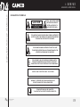
i-SERIES iD4 USER MANUAL ADVANCED AMPLIFIERS INFORMATION FOR USE iD4 i-SERIES TDA302USERGBE Revision E, 2014-02-11 Please visit our website www.camcoaudio.com for the latest version of this user manual. Please note that the leading version of CAMCO manuals is always the English one. © Copyright 2013 by CAMCO Produktions- und Vertriebs-GmbH für Beschallungs- und Beleuchtungsanlagen Fischpicke 5, D-57482 Wenden, Germany Telephone +49 (0) 2762 / 408-0 P.1 USER MANUAL i - SERIES i-SERIES IMPORTANT SAFETY INSTRUCTIONS ADVANCED AMPLIFIERS P.2 IMPORTANT SAFETY INSTRUCTIONS 1. General The amplifier may only be used in accordance with the information provided in the user manual. Before and during the usage of the amplifier please ensure that all recommendations, especially the safety recommendations as detailed in the user manual, are adhered to. The iD4 amplifier is designed for the amplification of pulsed audio signals. The amplifier should only be connected to speakers with an average impedance as indicated. 2. User Manual Read the information for use (user manual) and heed all warnings. Keep this user manual in a safe place during the lifetime of the amplifier. The user manual forms an integral part of the amplifier. Reselling the amplifier is only possible if the user manual is available. In case of reselling the amplifier, the reseller has to document any changes made to the amplifier in writing and pass the documentation on to the buyer. 3. Environments Use this amplifier only in E1, E2, E3, or E4 environments according to EN55103-2 “Electromagnetic compatibility – Product family standard for audio, video, and audio-visual and entertainment lighting control apparatus for professional use – Part 2: Immunity”. 4. Mounting / Placement Do not place this amplifier on an unstable cart, stand, tripod, bracket, or table. The amplifier may fall causing serious injury and serious damage to the product. Any mounting of the amplifier should follow the manufacturer´s instructions. Only mounting accessory shall be used which is recommended by the manufacturer. USER MANUAL i - SERIES 5. Power Cord Protection Power supply cords should be routed so that they are not likely to be walked on or pinched by items placed upon them or against them, paying particular attention to cords and plugs and the point where they exit from the amplifier. The disconnection device from mains (mains plug or external all-pole circuit breaker) shall remain readily operable and freely accessible at all times. 6. Heat Do not use this amplifier near any heat sources such as radiators, heat registers, stoves, or other apparatuses that produce heat. 7. Water and Moisture Do not expose this device to rain or moisture. Do not use this amplifier near water (for example swimming pools and fountains). Do not place any objects containing liquids, such as bottles or glasses, on the top of the unit. Do not splash liquids on the unit. IP-20 equipment. There is no protection against splashing water. 8. Ventilation Slots and openings in the cabinet are provided for ventilation to ensure reliable operation of the amplifier and to protect it from overheating. These openings must not be blocked or covered. This amplifier should not be installed unless proper ventilation is provided or manufacturer’s instructions have been adhered to. 9. Interference of External Objects and/or Liquids with the Appliance Never push objects of any kind into this amplifier through openings as they may touch dangerous voltage points or short-out parts that could result in fire or electric shock. Never spill liquid of any kind on the amplifier. i-SERIES IMPORTANT SAFETY INSTRUCTIONS ADVANCED AMPLIFIERS 10. Connections When you connect the amplifier to other equipment, turn off the power and unplug all of the equipment from the supply source. Failure to do so may cause an electric shock and serious personal injury. Read the user manual of the other equipment carefully and follow the instructions when making the connections. 11. Lightning For additional protection of this amplifier during lightning storms or when it is left unattended and/or unused for long periods of time, unplug it from the wall outlet. This will prevent damage to the amplifier due to lightning and power line surges. Disconnection from the mains power supply can only be achieved by removing the plug from the mains socket and by external disconnecting all poles from the mains. 12. Damages that require service Unplug this amplifier from the mains supply and refer to your dealer / distributor or other authorized repair workshop if any of the following situations occur: if liquid has been spilled or objects have fallen into the amplifier if the amplifier has been exposed to rain or moisture if the amplifier has been dropped or damaged in any other way if the power supply cord or plug has been damaged when the amplifier exhibits a distinct change from its normal function or performance in case the amplifier has been used in a dusty environment for quite a period of time 13. Servicing All service and repair work must be carried out by a dealer / distributor authorized by CAMCO. Do not attempt to service this amplifier yourself. As opening or removing covers may expose you to dangerous voltage or other hazards, the amplifier may only be opened by qualified personnel. Please refer to your dealer / distributor. P.3 USER MANUAL i - SERIES 14. Spare parts When spare parts are required, please ensure that the dealer / distributor only uses spare parts specified by the manufacturer. The use of unauthorized spare parts may result in injury and / or damage through fire or electric shock or other electricity-related hazards. 15. Safety check Upon completion of any service or repairs to this product, ask the dealer / distributor to perform safety checks to determine that the amplifier works properly. Recommendations on how to carry out the safety test can be found in DIN VDE 0701-1 “Maintenance, Modification and Test of Electronic Appliances“. 16. Cleaning Unplug this amplifier from the wall outlet before cleaning. Do not use liquid or aerosol cleaners. Clean only with dry cloth. 17. Packaging and shipping When shipping the iD4 amplifier, always use the original shipping carton and packing materials. For maximum protection repack the unit as it was originally packed at the factory. 18. Altitude (for China only) The amplifier shall only be operated at altitudes below or equal 2000 m. 19. Non-tropics (for China only) The amplifier shall only be operated in non tropic areas. i-SERIES EXPLANATION OF SYMBOLS ADVANCED AMPLIFIERS EXPLANATION OF SYMBOLS CAUTION RISK OF ELECTRIC SHOCK DO NOT OPEN CAUTION – HIGH VOLTAGE HAZARDS EXIST WITHIN THIS PRODUCT. REFER ALL SERVICING TO AUTHORIZED PERSONNEL. THE LIGHTNING FLASH WITH ARROW HEAD SYMBOL IS INTENDED TO ALERT THE USER TO THE PRESENCE OF UNINSULATED DANGEROUS VOLTAGE WITHIN THE PRODUCT’S ENCLOSURE. THE EXCLAMATION MARK IS INTENDED TO ALERT THE USER TO IMPORTANT INSTRUCTIONS ALSO FOR MAINTENANCE IN THE LITERATURE ACCOMPANYING THE AMPLIFIER. THE LIGHTNING FLASH WITH ARROW HEAD SYMBOL ALERTS THE USER TO DANGEROUSLY HIGH VOLTAGE AT THE OUTPUT CONNECTORS! THAT COULD POTENTIALLY BE LIFE THREATENING. CAUTION – RISK OF ELECTRIC SHOCK – DO NOT OPEN. WARNING – TO PREVENT FIRE OR SHOCK HAZARD, DO NOT EXPOSE THIS AMPLIFIER TO RAIN OR MOISTURE. THE AMPLIFIER MAY ONLY BE CONNECTED TO A SOCKET WITH A PROTECTIVE EARTH CONDUCTOR. P.4 USER MANUAL i - SERIES i-SERIES EC DECLARATION OF CONFORMITY ADVANCED AMPLIFIERS EC DECLARATION OF COMFORMITY EC Declaration of Conformity in accordance to EC Directives: Electromagnetic compatibility (Council Directive 2004/108/EC); low-voltage electrical equipment (Council Directive 2006/95/EC) Manufacturer´s Name: CAMCO Produktions- und Vertriebs-GmbH für Beschallungs- und Beleuchtungsanlagen Manufacturer´s Address: Fischpicke 5, D-57482 Wenden, Germany Declares that the product with the model name: CAMCO Power amplifier iD4 Conforms to the following standards: EN60065 Safety EN55103-1 Emission EN55103-2 Immunity The operating conditions and application environments presupposed in the information for use (user manual) are to be kept accordingly. Wenden, 17.06.2013 Joachim Stöcker P.5 USER MANUAL i - SERIES i-SERIES CONTENTS ADVANCED AMPLIFIERS P.6 Important Safety InstructionsP.2 Explanation of SymbolsP.4 EC Declaration of ComformityP.5 1. Welcome to CAMCOP.7 1.1 UnpackingP.7 2. The AmplifierP.8 2.1 iD4 – The FrontP.9 2.2 iD4 – The RearP.9 3. InstallationP.10 3.1 Mains SupplyP.10 3.2 On / Off SwitchP.10 3.3 MountingP.11 3.4 CoolingP.11 3.5 Signal InputsP.12 3.5.1 Analog InputP.12 3.5.2 AES InputP.12 3.6 Remote Control / Network InputP.12 3.7 Power OutputsP.12 3.7.1 SPEAKON® ConnectionP.12 3.7.2 Dual Channel OperationP.13 3.7.3 Mono Bridge OperationP.13 4. OperationP.14 4.1 User Interface ElementsP.14 4.1.1 Signal- / Protect-LEDs (multifunctional)P.14 4.1.2 Clip-LEDs (multifunctional)P.14 4.1.3 CHANNEL ButtonsP.14 4.1.4 ITEM ButtonsP.14 4.1.5 MENU ButtonsP.15 4.1.6 Rotary Encoder with Push ButtonP.15 4.2 Hot Key Functions – StandbyP.15 4.3 Standby FunctionP.15 4.4 Power Amp Protection SystemsP.16 4.4.1 Clip Limiter / Underimpedance LimiterP.16 4.4.2 SOA ProtectionP.16 USER MANUAL i - SERIES 4.4.3 DC ProtectionP.16 4.4.4 Over Current ProtectionP.16 4.4.5 Thermal ProtectionP.16 4.5 Mains ProtectionsP.16 4.5.1 Inrush Current Limitation P.16 4.5.2 Mains Over Voltage DetectionP.16 4.5.3 Mains Surge Overvoltage Protection P.16 4.5.4 Mains Failure DetectionP.16 4.5.5 Fuse Protection P.17 4.6 Main SMPS ProtectionsP.17 4.6.1 Over Current ProtectionP.17 4.7 FansP.17 4.8 Filter CleaningP.18 5. TroubleshootingP.19 5.1 Problem: No reaction when switching the amplifier onP.19 5.2 Problem: No soundP.19 5.3 Problem: Error message: “Error – amp switched off”P.19 6. SpecificationP.20 7. Typical Performance DiagramsP.23 8. Unit Conversion Equations and Lookup TableP.26 8.1 Unit Conversion EquationsP.26 8.2 Lookup TableP.26 9. Warranty InformationP.27 9.1 Summary of WarrantyP.27 9.2 Items Excluded from This WarrantyP.27 9.3 What CAMCO Will DoP.27 9.4 How to Obtain Warranty ServiceP.27 9.5 CAMCO Product ImprovementP.27 10. Service InformationP.28 11. Maintenance Information P.29 12. DecommissioningP.29 13. Company InformationP.30 14. Changes Made to The Amplifier / NoticesP.31 i-SERIES 1 WELCOME ADVANCED AMPLIFIERS 1. Welcome to CAMCO Thank you for choosing CAMCO products. You are now the proud owner of a very advanced CAMCO Amplifier. The technologies used in your amplifier are of the latest generation and designs delivering a far reaching set of results across all functions. The amplifier has been designed to be incorporated into a professional speaker system and is suitable for use across all applications from Touring Live Sound to Fixed Installations. Even if the amplifier has arrived in perfect condition, save all packing materials so you will have them if you ever need to transport the unit. Your speaker systems will benefit from the renowned CAMCO sonic quality as well as the many operating functions and features detailed within this manual which are incorporated within the design to maximise results. l NOTE Never ship the amplifier without the original packing materials. The CAMCO peace of mind long term manufactures warranty is our commitment to you that every CAMCO amplifier is ready to give you many years of faultless service. When shipping the iD4 amplifier, always use the original shipping carton and packing materials. For maximum protection, repack the unit as it was originally packed at the factory. WELCOME TO CAMCO! P.7 1.1 Unpacking Please unpack and inspect your new amplifier for any damage that may have occurred during transit. If damage is found, notify the transportation company immediately. Only you the consignee may initiate a claim for shipping damage. CAMCO will be happy to cooperate fully as needed. Please save the shipping carton as evidence of damage for the shipper’s inspection. USER MANUAL i - SERIES i-SERIES 2. The Amplifier The iD4 is a Class-H power amplifier with a power output of: Power output iD4 2 THE AMPLIFIER ADVANCED AMPLIFIERS Operating mode 1× 4 500 W mono bridge @ 8 Ω peak 1× 3 800 W mono bridge @ 8 Ω 1× 3 000 W mono bridge @ 4 Ω 2× 2 250 W dual channel @ 4 Ω peak 2× 2 000 W dual channel @2,7 Ω peak 2× 1 900 W dual channel @ 4 Ω 2× 1 500 W dual channel @ 2 Ω iD4 amplifiers are fitted with Switched Mode Power Supplies (SMPS), which significantly reduces the weight and size (only 2U) of the amplifier. Using SMPS, the 2 symmetrical supply voltages of the power amplifier are more stable than the power supplies used in conventional amplifiers. The iD4 has been designed as a powerful two channel amplifier with onboard 64 bit DSP processing. Both amplifier settings and DSP settings can be user adjusted to match a speaker systems specifications. With up to 100 onboard speaker pre-set storage capability, fine tuning of a system or differing systems is fast, easy and strait forward; the user interface is designed to be intuitive allow for quick familiarisation. The combination of both power amplifier and on-board DSP technologies used in the iD4, provide the level of control and audio quality expected in any professional applications. The iD4, a very powerful and complete speaker management system, with optimum flexibility and maximum control and security. Since some of the externally mounted controls have multiple functions, it is important that users should familiarise themselves thoroughly with the entire range of controls. P.8 USER MANUAL i - SERIES i-SERIES ADVANCED AMPLIFIERS 2 THE AMPLIFIER 2.1 iD4 – The Front Signal-LEDs Clip-LEDs Character LCD Channel buttons Item buttons Menu buttons Rotary encoder with push button Removable air filter system Cooling air inlet vents On/Off switch 2.2 iD4 – The Rear XLR – line input 1 XLR – line input 2 AES input Ethernet network input Cooling air outlet vents SPEAKON® output 2 SPEAKON® output 1 Rating plate AC power cable iD 4 220 V ~ 50 / 60 Hz 11,3 A 1220 W 1900 W / 4 Ohm MODE L: OUTPUT PWR P E R C H/IMP: SER. NO. : P.9 USER MANUAL i - SERIES xxxxx MADE I N GE R MANY i-SERIES 3 INSTALLATION ADVANCED AMPLIFIERS 3. Installation 3.1 Mains Supply When mounting or connecting the amp always disconnect it from mains. Only connect the iD4 amplifier to an appropriate AC circuit and outlet, according to the requirements indicated in the second line on the rating plate. iD4 iD4 120 V ~ 50/60 Hz 22,6 A 1220 W 1900 W / 4 Ohm 220 V ~ 50/60 Hz 11,3 A 1220 W 1900 W / 4 Ohm Amplifier is switched on iD4 230 V ~ 50/60 Hz 11,3 A 1220 W 1900 W / 4 Ohm Exemplary rating plates for the three available amplifier variants. Power supply data of all available variants: iD4 Operating condition Mains current (4 Ω / 2 Ω) Power Output consumption power (4 Ω / 2 Ω) Amplifier standby (power off) < 0,5 A 8W 0W Idle (amplifier powered on) 1,3 A 70 W 0W 8,5 / 10 A 1 220 / 1 500 W 500 W 250 W per channel Mains current draw and power consumption @ 230 V, 50 Hz Measured with pink noise with crest factor of 12 dB to represent typical music signal. For 120 V mains operation, the current values can be multiplied by 2. P.10 USER MANUAL i - SERIES 3.2 On / Off Switch The On / Off Switch is a rocker-type switch. It is located on the right side of the front panel. To turn the amplifier on, press on the upper part of the switch. During power up the Clip- and Signal-LEDs from both channels will light up in red for a few seconds. To turn the amplifier off, press on the lower part of the switch. Amplifier is switched off l NOTE This switch does NOT disconnect the amplifier from mains. Disconnecting the amplifier from the main power supply can only be achieved by disconnecting the mains plug or by an external all-pole disconnection (e.g. a mains / circuit breaker). The mains plug or circuit breaker therefore has to be freely accessible at all times. Disconnect the mains plug from the mains during a lightning storm or when the amplifier remains unused or unsupervised for a prolonged period of time. The switch initiates start-up by activating the inrush current limiter. As soon as the power amplifier is connected to the mains power supply, a voltage is supplied to both the line-filter and the fused input of the controllable rectifier. If a power cut occurs while the amplifier is switched on, it will restart auto matically once the power supply has been restored. All amplifier settings prior to the loss of power will be maintained. i-SERIES 7,50 mm 3.3 Mounting Use four screws and washers when mounting the amplifier to the front rack rails. For mobile use, the amplifier should also be secured using the 19” mounting elements on the rear panel. 88,10 mm 10,50 mm Note that continous high power draw at low load impedance (equal or less than approx. 2,7 Ω) can drive the amplifier into thermal limitation. So please check the amplifier temperatures on the display or in the DSP control application and reduce the onput levels if necessary. 465,0 mm P.11 USER MANUAL i - SERIES 431,00 mm 409,60 mm 418,60 mm 442,00 mm 483,00 mm 3.4 Cooling The air is taken in from the front and out through the back. It is essential that while the amplifier is running the air is able to circulate around it freely. The efficiency of the cooling will depend on the immediate environment (e.g. an enclosed rack, direct sunlight). If the amp is installed in a case, the open area at the back of the case must be at least 140 cm². This area should be in line with the amplifier. If this cannot be achieved a forced ventilation system has to be used. 76,20 mm 3 INSTALLATION ADVANCED AMPLIFIERS i-SERIES 3 INSTALLATION ADVANCED AMPLIFIERS 3.5 Signal Inputs 3.7 Power Outputs 3.5.1 Analog Input XLR:Pin 1 = Ground Pin 2 = Hot (inphase) Pin 3 = Cold (out of phase) 3.7.1 SPEAKON® Connection Both SPEAKON® connectors are connected to channel 1 and channel 2 outputs. The pin configuration of the SPEAKON connectors is as follows: Always use symmetrical (balanced) shielded cable to connect the amplifier. 3.5.2 AES Input The digital AES XLR input accepts any AES / EBU signals (pro or consumer format) in 16 to 24 bit resolution and 44,1, 48, 88,2, or 96 kHz samplig frequency. This wide input frequency range of is guaranteed by an integrated sample rate converter (SRC) chip. 3.6 Remote Control / Network Input The Ethernet Link network connector allows you to access the iD4 from a host computer for remote control, firmware update and downloading DSP presets. The iD4 is configured by default to use DHCP for automatic IP address assignment in the network. If not desired, this feature can be set through the DSP Control application. SPEAKON® right: (View at the back) Pin 1+ Pin 1– Pin 2+ Pin 2– Channel 1 Channel 1 Channel 2 Channel 2 signal ground signal ground SPEAKON® left: (View at the back) Pin 1+ Pin 1– Pin 2+ Pin 2– Channel 2 Channel 2 Channel 1 Channel 1 signal ground signal ground ! WARNING! SPEAKON® connectors marked with the lightning flash indicate high voltages that are potentially life threatening. Wiring to these terminals requires installation by an instructed person or the use of ready-made leads or cords. Custom wiring should only be made by qualified personnel. To prevent electric shock, do not operate the amplifier with any of the con ductor portion of the speaker wire exposed. l NOTE For reasons of safety and performance, use only high-quality fully in su lated speaker cables of stranded copper wire. Use the largest wire size that is economically and physically practical, and make sure the cables are no longer than necessary. l NOTE When connecting speaker cabinets in parallel, always use all the contacts in both SPEAKON® connectors. If not, this may cause permanent damage to the connectors and considerably reduce performance. P.12 USER MANUAL i - SERIES i-SERIES 3 INSTALLATION ADVANCED AMPLIFIERS 3.7.2 Dual Channel Operation Two fully independent amplifier channels (“Stereo” – normal operating mode). iD4 In 1 In 2 Zmin = 2 Ω for Dual Channel operation 3.7.3 Mono Bridge Operation One-channel mono bridged operation. iD4 In 1 180° In 2 Zmin = 4 Ω for Mono Bridge operation In this mode the channel 2 amplifier stage processes the identical input signal than channel 1, but with reversed phase. The channel 2 input signal is not used / ignored. The loudspeaker load must then be connected between the two positive channel outputs (pin 1+ and pin 2+) using a specially configured SPEAKON® connector / cable. This effectively doubles the maximum output voltage. But please note that this also doubles the minimum allowed loudspeaker impedance Zmin. P.13 USER MANUAL i - SERIES ! WARNING! In Mono Bridge Operation RMS output voltages can be as high as 200 VAC. Wiring to the speaker loads must conform to NEC class 3 safety standards or its equivalent that meets all national and local electric codes. All customer specific cables may only be manufactured by qualified suppliers / personnel. All cabling or rewiring work must be carried out by qualified personnel. i-SERIES 4 OPERATION ADVANCED AMPLIFIERS 4. Operation cates heavy clipping. These LED’s exclusively indicate hardware clipping of the power amplifier stage. Possible internal DSP limitation and compression is not indicated here. 4.1 User Interface Elements l NOTE This chapter only describes the basic user interface operation and functions. Please refer to the separate DSP Control manual for an explanation of the extensive Digital Signal Processing (DSP) options and advanced features offered by the remote application. 4.1.1 Signal- / Protect-LEDs (multifunctional) The Signal-LEDs are illuminated in green when the voltage level at the outputreachesapprox.4V;thiscorrespondstoapowerof4Wintoa4Ω load. The channel Signal-LEDs are illuminated red when the amplifier is in Protect Mode (Mute), for example because of persistent DC-voltage at the outputs or overheating. When switching the amplifier on, the Signal-LEDs will also light red for a few seconds while the DSP is starting up (along with the Clip-LEDs). In case the FuseProtect limiter is activated, it is possible that the (green) Signal-LED’s will glow in orange or red colour for short periods of time while the amplifier is playing music. à See also chapter 4.5.5 Fuse Protection 4.1.2 Clip-LEDs (multifunctional) The colour of the bi-coloured LED changes between orange and red, depending on the clip intensity. Orange indicates light clipping, red indi- P.14 USER MANUAL i - SERIES 4.1.3 CHANNEL Buttons The CHANNEL buttons allow to select the channels to make adjustments on. Selectable items are In 1 to In 4 and Out 1 and Out 2 (depending on user and access rights). Note that if channels are linked the settings will always affect both linked channels. In this case the channel selection will display In 12, In 34 or Out 12. 4.1.4 ITEM Buttons The ITEM buttons allow you to navigate trough all parameters which can be set from the front panel. Note that not all parameters can be set from the amplifier user interface. For full and easier access to all settings and parameters please use the DSP Control remote control application. The available parameters are: à Gain settings in 0,25 dB steps Gain Smaller steps (0,01 dB) can be set via the DSP Control remote application. à Selects the source of the chosen input channel Source Setting only available for the Inputs 1 to 4 à Set the signal delay Delay à Configure the low pass filter section Low Pass High Pass à Configure the high pass filter section PEQ 1 to 10 à Configure the 10 parametric EQ bands à Set the Output channel phase (normal or inverted) Phase Setting only available for Output 1 and 2 i-SERIES 4 OPERATION ADVANCED AMPLIFIERS à Configure the peak limiter Limiter Compressorà Configure the compressor à Selects if Input 1 & 2, Input 3 & 4 or Output 1 & 2 Link shall be linked All settings and selections are done through the rotary encoder. Changes will take effect immediately. 4.1.5 MENU Buttons The left (3) MENU button will always act as an ESCAPE / EXIT button. The right (4) MENU button offers following sub-menus, accessible through repeated pressing on the right MENU button: Load preset Save preset Access Level control Auxilliary information: à Version Info Serial Number (SN) à Version Info FW Version (SW) à Version Info Hardware Version (HW) à IP Address à MAC Address à Temperature of both amplifier stages Inside the Auxilliary information menu you can navigate through the sub menus with the encoder wheel. Note that in this menu the encoder will only work in a round-robin fashion, regardless of the direction you turn it. l NOTE The left (3) MENU button always acts as an ESCAPE / EXIT button in all menus. 4.1.6 Rotary Encoder with Push Button The rotary encoder allows to make swift adjustments of parameters (like for example the Gain settings) by simply turning it in the desired direction. In some menus the push-function of the encoder will act as an ENTER button (for example when loading or saving presets) or will allow you to access the parameter’s sub-settings for the Low Pass, High Pass, PEQ, Limiter and Compressor. P.15 USER MANUAL i - SERIES 4.2 Hot Key Functions – Standby To set the iD4 to standby mode simply press both (34) MENU buttons simultaneously for more than three seconds. You will then be asked if you want to switch to Standy Mode. Pressing the encoder knob (without rotating it) will then power down the main power supply of the iD4. The standby function can of course also be controlled by the DSP Control remote application. 4.3 Standby Function The iD4 offers the possibility to set the amplifier into standby mode either from the user interface or by the DSP Control remote application. In standby mode the iD4 will power down it’s main SMPS, thus saving energy while at the same time staying accessible via network connection. From the amplifier’s user interface this function is accessible through a Hot Key function as described above. Inside the DSP Control remote application you can access this function through the Unit menu. An additional feature is the automatic standby function which will set the iD4 in standby mode if no input signal (analogue and / or AES) is applied for a certain period of time. This delay time can be set individually (or switched off) inside the DSP Control remote application through the Unit à Configure à Auto Standby menu. l NOTE If the amplifier has been set into standby through the Auto Standby function, automatic wakeup will only work if digital AES input signal is applied again. Applying analogue signal again will not wakeup the amplifier again. When unsing analogue input signal, exiting the automatic standby mode must be done manually through the user interface or the DSP Control remote application. So please consider this carefully before using the Auto Standby function with analogue input signal. i-SERIES 4 OPERATION ADVANCED AMPLIFIERS 4.4 Power Amp Protection Systems 4.4.1 Clip Limiter / Underimpedance Limiter The DSP section of the iD4 offers various limiter and compressor settings, both on the signal inputs and on the signal outputs. Those limiters and compressors can be adjusted and even switched off completely if desired. Disabling the limters is done by setting the thresholds to their highest values. But in case the amplifier is driven into hardware clip (i. e. when the ClipLED is glowing orange or red) for longer periods of time, the threshold setting of the output limiter will automatically be reduced temporarily. Note that this is automatically done inside the amplifier and cannot be seen in the DSP control application. This automatic threshold reduction will especially take place at low output impedances (smaller 4 Ω) and high output powers and shall prevent the amplifier from being operated in continuous hard amplifier cliping. 4.4.2 SOA Protection Whenever the power transistors leave their Safe Operation Area (SOA), the SOA-protection switches back the rail of the respective channel. 4.4.3 DC Protection Each output of the power amp is constantly monitored for persistent DC voltage levels. If the 3 V thresholds are exceeded at any of the outputs, the corresponding channel will be muted. If DC was only detected for a short moment, the amplifier will release mute and work as normal. If DC is detected for longer periods or repeatedly, the amplifier will switch to standby mode and disable the main power supply. If this happens the display will indicate “Error – amp switched off”. In this case, switch off the amplifier for at least 4 minutes and switch the amplifier on again. P.16 USER MANUAL i - SERIES 4.4.4 Over Current Protection Over current is permanently controlled in the output stage. There are two limiting levels of over current depending on output voltage. These limits will be set automatically. This improves reliability without degrading sound quality when driving complex loads. 4.4.5 Thermal Protection There are several sensors inside the amplifier in order to ascertain tem perature data. If a temperature of more than 85 °C is detected at the heat sinks, the input signal on that channel is reduced. 4.5 Mains Protections 4.5.1 Inrush Current Limitation Within 2 seconds of the amplifier being switched on, the inrush current limiter will increase mains current from nearly zero to nominal value. This value depends on program material, output level and speaker loads. 4.5.2 Mains Over Voltage Detection Mains over voltage detection is always operative. When the mains voltage exceeds approx. 263 V (220 / 230 V operation) or 134 V (110 / 120 V operation), the amplifier will be switched off. The system will try to restart in intervals and will return with a soft start when the regular mains voltage returns. 4.5.3 Mains Surge Overvoltage Protection The iD4 is fitted with a varistor unit, protecting the SMPS from sporadic surge overvoltages coming from the mains distribution. 4.5.4 Mains Failure Detection Mains failure detection is always operative. When the mains supply is interrupted for about 2 mains cycles, the amplifier will be switched off. When the mains voltage returns to a normal value, a soft start occurs. i-SERIES 4 OPERATION ADVANCED AMPLIFIERS P.17 4.5.5 Fuse Protection When driving the iD4 at very high output levels over a longer period of time (i.e. several seconds and minutes) the average mains current draw can become very high. In such situations, the FuseProtect limiter will reduce the output signal in order to prevent the external mains breaker from tripping. But this limiter in turn will not affect the output signal on dynamic music signal and short current peaks, thus guaranteeing the full available peak output power. Please note that the FuseProtect limiter only controls the average mains input current, not the short term peak input current. This means that with very dynamic music signals the (short term) input current can still reach very high levels, which can be very demanding for a mains distribution. If active, the operation of the FuseProtect limiter can be seen by short orange or red glowing of the Signal-LED’s. USER MANUAL i - SERIES 4.6 Main SMPS Protections 4.6.1 Over Current Protection Main SMPS (Switched Mode Power Supply) transformer current is continuously monitored. If over current occurs, the main SMPS immediately stops working. Should there be an internal failure, this feature prevents other parts being damaged. 4.7 Fans The fans mounted in the iD4 operate permanently, but as long as the temperature remains below 40 °C they run at their slowest speed and can hardly be heard. The highest detected temperature from either channel controls the speed of the fans: above 40 °C the speed is increased until it reaches its maximum value. i-SERIES 4 OPERATION ADVANCED AMPLIFIERS 4.8 Filter Cleaning The air intake on the front of your iD4 amplifier is fitted with a removable filter system. If the filter becomes clogged, the unit will not cool as efficiently as it should and may result in reduced output levels. iD4 Filter Assembly Foam filter Front frame Screw ! WARNING! Turn off and disconnect the amplifier from the mains before removing the front frame. To clean or replace the filter just slightly unscrew the fixing screw with the help of a 3 mm allen key. The screw will be held back by a small plastic spacer on the back of the frame to avoid losing it. Then shift the front frame slightly to the right. Then you should be able to remove the frame from the amplifier completely (pull gently to avoid any bending of the front frame). P.18 USER MANUAL i - SERIES i-SERIES 5 TROUBLESHOOTING ADVANCED AMPLIFIERS 5. Troubleshooting 5.1 Problem: No reaction when switching the amplifier on If nothing happens when switching the amplifier on (i.e. the display stays totally dark, no message inside the display), please check following points: Check mains cable and plug Confirm that the AC outlet works by plugging in any other device 5.2 Problem: No sound If no sound can be heard on the outputs please check following DSP settings (through the DSP control application): Input source selection Input and output gain settings Input and output limiter settings If digital (AES) input signal is used, please check AES signal source (samplig frequency, bit resolution and signal quality (long cables)) 5.3 Problem: Error message: “Error – amp switched off” This error message indicates an internal error which forced the main power supply (SMPS) to be switched off. This can be caused by: Detection of permanent DC on the outputs Detection of amplifier stage malfunction (protect) Detection of main SMPS error You can try to power-cycle the amplifier to reset all amplifier stage detection circuits. This might help in case the DC or amplifier fault was caused by an invalid input signal (e.g. an extremely high frequent or extremely distorted input signal). For this please switch off the amplifier for at least 4 minutes and switch the amplifier on again. If the message still appears after this procedure the fault is permanent and the amplifier requires servicing. P.19 USER MANUAL i - SERIES i-SERIES 6 SPECIFICATION ADVANCED AMPLIFIERS 6. Specification Output power 1 kHz, THD ≤ 1%, in dual channel operation 2 × 2 × 2 × 2 × 2 × 600 W @ 16 Ω 1 100 W @ 8 Ω 1 900 W @ 4 Ω 1 950 W @ 2,7 Ω 1 500 W @ 2 Ω Peak output power 1 kHz, single sine wave in dual channel operation 2 × 2 × 2 × 2 × 2 × 630 W @ 16 Ω 1 240 W @ 8 Ω 2 250 W @ 4 Ω 2 000 W @ 2,7 Ω 1 500 W @ 2 Ω Mono bridge operation output power 1 kHz, THD ≤ 1%, in mono bridge operation 1 × 2 200 W @ 16 Ω 1 × 3 800 W @ 8 Ω 1 × 3 000 W @ 4 Ω 1 kHz, single sine wave in mono bridge operation 1 × 2 480 W @ 16 Ω peak* 1 × 4 500 W @ 8 Ω peak* 1 × 3 000 W @ 4 Ω peak* 70 / 100 V line operation output power 1 kHz, THD ≤ 1% 2 × 1 800 W @ 70 V line 1 ×2 500 W* @100 V line typical values @ 230 V / 50 Hz duration limited by fuse / thermal protection for RL ≤ 8 Ω typical values @ 230 V / 50 Hz, may be subjected to component tolerances typical values @ 230 V / 50 Hz duration limited by fuse / thermal protection for RL ≤ 16 Ω typical values @ 230 V / 50 Hz, may be subjected to component tolerances * only possible in mono bridge operation (single channel) Circuitry Signal to noise-ratio 10 Hz – 20 kHz, 8 Ω load Power consumption @ 230 V * both channels driven at 250 W output power (approx. of max. THD limited output power with pink noise to represent typical music signal) Bipolar, Class H 2 step high efficiency circuit > 102 dB (unweighted) > 105 dB (A-weighted) Amplifier standby (power off): 8 W Idle (Amp powered on): 70 W 4 Ω: 1 220 W* 2 Ω: 1 500 W* Maximum output voltage ± 142 V peak Maximum output current ± 39 A peak in dual channel operation; typical values @ 230 V / 50 Hz in dual channel operation; typical values, may be subjected to component tolerances We reserve the right to make technical alterations without prior notice. P.20 USER MANUAL i - SERIES i-SERIES 6 SPECIFICATION ADVANCED AMPLIFIERS Frequency response @ 4 Ω load with 120 W ouptut power THD+N over frequency @ 4 Ω load with 120 W output power Damping factor 8 Ω load, 1 kHz and below Input impedance Amplifier gain Maximum analogue differential input level Level attenuation Minimum loudspeaker load impedance Lower values are safe, but out of specification. No performance guarantees can be given when driving lower impedances than specified. Protection circuits Analogue limiters (HW) Cooling LED indicators Input connectors Power output connectors Modes of operation Input sources A/D – D/A converters 10 Hz – 20 kHz: ± 0,175 dB 20 Hz – 10 kHz: < 0,02 % > 400 29 kΩ balanced 32 dB default (adjustable through DSP) +20,5 dBu / 8,2 VRMS / 11,6 VPeak Done through DSP in 0,25-dB-steps Zmin = 2 Ω for Dual-Channel operation Zmin = 4 Ω for Mono Bridge operation Inrush-current limitation, mains surge overvoltage protection, temperature monitoring of heatsinks, output DC protection, temperature dependent SOA protection, mains fuse protection, output current limitation, thermal limitation Clip / Underimpendance Limiter, FuseProtect Limiter Two temperature dependent speed-controlled axial fans LEDs for signal / protect and clip Two 3-pin XLR female analogue input connectors, pin 2 = hot (inphase) Two 3-pin XLR male passive loop through connectors One 3-pin XLR female AES (digital) input connector One Ethernet connector RJ45 One 4-pole SPEAKON® connector for each output channel (bi-amping possilbe) Dual channel (Stereo), mono bridge Analogue, AES 24 bit / 96 kHz We reserve the right to make technical alterations without prior notice. P.21 USER MANUAL i - SERIES i-SERIES 6 SPECIFICATION ADVANCED AMPLIFIERS Latency Digital inputs AC mains * Approximative mains voltage range where the amplifier can be used. Amplifier output power performance will decrease with lower mains voltages than the rated 230 V / 220 V / 120 V and slightly increase with higher mains voltages. Operating temperature Dimensions (W × H × D) Net weight Shipping dimensions (W × H × D) Shipping weight Min. 0,58 ms AES / EBU, 16 to 24 bit, 44,1, 48, 88,2, or 96 kHz 230 V AC, 50 / 60 Hz (for Europe), 190 – 263 V* 220 V AC, 50 / 60 Hz (for China), 190 – 263 V* 120 V AC, 50 / 60 Hz (for US), 95 – 134 V* +5 °C to +55 °C / +41 °F to +131 °F 483 × 88,1 × 419 mm / 19 × 3,5 × 16,5 inches (19”, 2U) 9,4 kg / 20,7 lbs 600 × 105 × 527 mm / 23,3 × 4,1 × 20,7 inches 11 kg / 24,3 lbs We reserve the right to make technical alterations without prior notice. P.22 USER MANUAL i - SERIES i-SERIES 7. Typical Performance Diagrams 1 +1 +0,5 0 -0,5 0,1 -1,5 % dBr -1 -2 0,01 -2,5 -3 -3,5 10 100 1k 10k 20k 50k -50 -40 Hz Figure 7.1 Gain vs. frequency, 120 W output power (Measurement of a typical performance @ 2 Ω & 4 Ω) -30 dBu -20 -10 0 4 Figure 7.3 THD @ 1 kHz vs. input level @ 2 Ω load (32 dB amplifier gain) (Measurement of a typical performance of Ch 1 & Ch 2) 1 1 0,1 0,1 % 0,01 0,01 0,001 -60 0,001 -50 -40 -30 -20 -10 0 dBu Figure 7.2 THD @ 1 kHz vs. input level @ 4 Ω load (32 dB amplifier gain) (Measurement of a typical performance of Ch 1 & Ch 2) P.23 0,001 -60 -4 % 7 TYPICAL PERFORMANCE DIAGRAMS ADVANCED AMPLIFIERS USER MANUAL i - SERIES 10 20 100 1k Hz Figure 7.4 THD vs. frequency, 120 W output power (Measurement of a typical performance @ 2 Ω & 4 Ω) 10k 20k i-SERIES 0 0 -10 -20 -20 -30 dBr dBr -40 -60 -60 -100 -70 -120 -80 10 100 1k 10k 10 20k 100 Hz 1k 10k 20k Hz Figure 7.5 Channel separation vs. frequency @ 120 W / 4 Ω (Measurement of a typical performance of Ch 1 à Ch 2 & Ch 2 à Ch 1) Figure 7.7 Common mode rejection ratio vs. frequency (Measurement of a typical performance of Ch 1 & Ch 2) 10 100 10 1 1 100 m V 0,1 10 m 1m 100 µ 0,01 10 µ 0,001 -60 1µ -50 -40 -30 -20 -10 dBu Figure 7.6 DIM100 vs. input level (32 dB amplifier gain) (Measurement of a typical performance of Ch 1 & Ch 2) P.24 -40 -50 -80 % 7 TYPICAL PERFORMANCE DIAGRAMS ADVANCED AMPLIFIERS USER MANUAL i - SERIES 0 10 10 100 1k 10k 20k Hz Figure 7.8 FFT of noise level (no input signal applied, analog input, 32 dB amplifier gain) (Measurement of a typical performance of Ch 1 & Ch 2) i-SERIES P.25 1000 100 m 800 damping factor 300 m Ω 7 TYPICAL PERFORMANCE DIAGRAMS ADVANCED AMPLIFIERS 10 m 600 400 200 0 2m 20 100 1k Hz Figure 7.9 Output impedance vs. frequency @ 1 Amp RMS injected current equivalent 11 mΩ + 2,1 µH (Measurement of a typical performance of Ch 1 & Ch 2) USER MANUAL i - SERIES 10k 20k 10 100 1k 10k 20k Hz Figure 7.10 Damping factor into 8 Ω (equation: damping factor = loaded impedance / amplifier output impedance) (Measurement of a typical performance of Ch 1 & Ch 2) i-SERIES 8. Unit Conversion Equations and Lookup Table 8.1 Unit Conversion Equations Unit conversion VRMS à dBu VRMS à dBV dBu à VRMS dBV à VRMS 8Ω VRMS à VPeak 2Ω VRMS à Output power 8.2 Lookup Table VRMS VPeak dBu dBV Equation 4Ω 8 UNIT CONVERSION EQUATIONS ADVANCED AMPLIFIERS Output power in W (8 Ω) Output power in W (4 Ω) Output power in W (2 Ω) 1 2,83 2,22 0,00 0,13 0,25 0,50 2 5,66 8,24 6,02 0,50 1,00 2,00 3 8,49 11,76 9,54 1,13 2,25 4,50 4 11,32 14,26 12,04 2,00 4,00 8,00 5 14,14 16,20 13,98 3,13 6,25 12,5 6 16,97 17,78 15,56 4,50 9,00 18,0 7 19,80 19,12 16,90 6,13 12,3 24,5 8 22,63 20,28 18,06 8,00 16,0 32,0 9 25,46 21,30 19,08 10,1 20,3 40,5 10 28,29 22,22 20,00 12,5 25,0 50,0 12 33,95 23,80 21,58 18,0 36,0 72,0 15 42,43 25,74 23,52 28,1 56,3 112,5 20 56,58 28,24 26,02 50,0 100,0 200,0 30 84,87 31,76 29,54 112,5 225,0 450,0 40 113,15 34,26 32,04 200,0 400,0 800,0 50 141,44 36,20 33,98 312,5 625,0 1 250,0 60 169,73 37,78 35,56 450,0 900,0 1 800,0 70 198,02 39,12 36,90 612,5 1 225,0 2 450,0 80 226,31 40,28 38,06 800,0 1 600,0 3 200,0 90 254,60 41,30 39,08 1 012,5 2 025,0 4 050,0 100 282,89 42,22 40,00 1 250,0 2 500,0 5 000,0 120 339,46 43,80 41,58 1 800,0 3 600,0 7 200,0 150 424,33 45,74 43,52 2 812,5 5 625,0 11 250,0 Values in grey are calculated only. The iD4 is not able to deliver these output powers. P.26 USER MANUAL i - SERIES i-SERIES 9 WARRANTY INFORMATION ADVANCED AMPLIFIERS P.27 9. Warranty Information 9.1 Summary of Warranty CAMCO guarantees the iD4 amplifier to be free from defective material and / or workmanship for a period of six (6) years from the date of sale. When a defect occurs under normal installation and use, CAMCO will repair the product under this warranty. In this event, please return the amplifier to your dealer / distributor together with a copy of your sales receipt as proof of purchase. 9.4 How to Obtain Warranty Service You must notify your dealer / distributor of your need for warranty service. All components must be shipped in the original packaging. This warranty provides that examination of the returned product must indicate in our judgment a manufacturing defect. 9.2 Items Excluded from This Warranty CAMCO is not liable for any damage caused by shipping accidents, misuse, abuse, operation with incorrect AC voltage, operation with faulty peripheral equipment, modification or alteration without prior factory approval, service by an unauthorised service center and normal wear and tear. Amplifiers on which the serial number has been removed or defaced are not eligible for warranty service. 9.3 What CAMCO Will Do CAMCO (or its appointed agent) undertakes to rectify any defect regardless of the reason for failure (unless excluded from this warrenty), by repair, replacement or refund as it sees fit. USER MANUAL i - SERIES 9.5 CAMCO Product Improvement CAMCO reserves the right to improve the technical standard of its products without giving prior notice. If in any doubt, please consult your dealer / distributor or contact CAMCO directly for clarification. i-SERIES 10 SERVICE INFORMATION ADVANCED AMPLIFIERS 10. Service Information PLEASE ENCLOSE THIS COMPLETED FORM WITH THE AMPLIFIER DO NOT SEND SEPARATELY Owner’s Information Nature of problem occurred Please describe the conditions that existed when the problem occured and what attempts were made to correct it: Company Name: Contact: Address: Telephone: Facsimile: E-Mail Address: Model: Other equipment in your system: Serial Number: Purchase Date: Expired Warranty If the warranty has expired, payment will be: Cash / Cheque VISA MasterCard Shipping Address To transport the amplifier, the original packing materials must be used. Please return the amplifier to the address on the right side or your nearest CAMCO appointed distributor. P.28 USER MANUAL i - SERIES Our web site: www.camcoaudio.com provides a complete list of CAMCO dealers / distributors. CAMCO Produktions- und Vertriebs-GmbH für Beschallungsund Beleuchtungsanlagen, Fischpicke 5, 57482 Wenden, Germany i-SERIES 11 MAINTENANCE INFORMATION / 12 DECOMISSIONING ADVANCED AMPLIFIERS P.29 11. Maintenance Information Cleaning and servicing the inside of the amplifier must never be carried out by unqualified personnel. The amplifier must never be opened by unqualified personnel. Cleaning and servicing work on the inside of the amplifier must only be carried out by qualified personnel. Qualified personnel is defined as a person who has gained specialised relevant knowledge of electronic engineering through education, training, and experience, and who has sufficient knowledge of all relevant governmental work safety regulations to be in a position to judge the safe functioning of power amplifiers based on technical rules according to IEC 60065 (IEC 60065 (DIN EN 60065) “Safety Requirements for Audio, Video or simlar Electronic Appliances”). In order to guarantee the safe functioning of the amplifier, it has to be checked regularly, depending on its application but at least once a year, by a properly qualified person. Advice on how to carry out these checks can be found in DIN VDE 0702-1 “Safety Checks for Electronic Appliances” . An amplifier that is considered to be unsafe must be labelled accordingly and stored in a safe place to prevent this amplifier being used mistakenly. USER MANUAL i - SERIES 12. Decommissioning During the decommissioning process of the amplifier, all legally prescribed rules and procedures must be adhered to. i-SERIES 13 COMPANY INFORMATION ADVANCED AMPLIFIERS P.30 13. Company Information Mailing Address: CAMCO Produktions- und Vertriebs-GmbH für Beschallungs- und Beleuchtungsanlagen Fischpicke 5 57482 Wenden Germany Telephone: +49 (0) 27 62 / 408 - 0 Facsimile: +49 (0) 27 62 / 408 - 10 Internet: www.camcoaudio.com E-Mail: [email protected] USER MANUAL i - SERIES i-SERIES 14 CHANGES MADE TO THE AMPLIFIER / NOTICES ADVANCED AMPLIFIERS P.31 14. Changes Made to The Amplifier / Notices l NOTE / IMPORTANT: Please consider that any changes made to the amplifier have to be documentated in writing and passed on to the buyer in the event of resale! USER MANUAL i - SERIES i-SERIES 14 CHANGES MADE TO THE AMPLIFIER / NOTICES ADVANCED AMPLIFIERS P.32 USER MANUAL i - SERIES