1
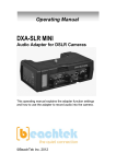
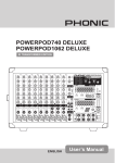
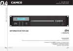
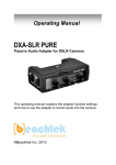
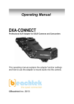
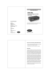
Operating Manual DXA-SLR ULTRA Professional XLR Adapter for DSLR Cameras This operating manual explains the adapter function settings and how to use the adapter to record audio into the camera. ©Beachtek Inc. 2014 Thank You for Purchasing a BeachTek Product Congratulations on purchasing the DXA-SLR ULTRA from the makers of the world’s most popular audio adapters for DSLR cameras. This adapter is packed with features to enable you to record professional audio directly to your camera. Before using this high quality device, please read this guide thoroughly to obtain the highest performance. Please contact us if you have any problems or questions. Description The BeachTek DXA-SLR ULTRA is a two-channel, active XLR adapter with built-in preamplifiers for attaching external microphones and other audio gear to any DSLR camera that has a built-in mic jack. It can also be used with any camcorder or other audio recording device that has a mic jack. The DXA-SLR ULTRA uses exceptionally low noise, wide bandwidth preamplifiers for superb audio. This allows you to record high quality audio directly to the camera which will always be in sync with the video. Direct audio recording eliminates the need to have a separate audio recording device and syncing the audio in post editing. The DXA-SLR ULTRA is very easy to set up and use. It allows you to connect a wide variety of audio devices including wireless systems, mixers, sound boards and professional condenser microphones that require phantom power to operate. The inputs are transformer balanced for isolation and enhanced circuit protection. Built-in VU meters makes it easy to verify the proper input levels at a glance, while the level controls allow you to adjust the output signal for optimum recording. Built-in fast acting limiters prevent distortion from overly hot inputs for worry free operation. The phone jack lets you monitor the audio from the adapter during recording, or camera during playback. A unique feature of the DXA-SLR ULTRA is the detachable rod support base to easily attach a matte box, follow focus and other gear to a rod support rig. The adapter mounts to the bottom of the camera and can also be mounted to any standard tripod. Warnings Ensure that the VOLUME control is set low to avoid excessively loud audio from damaging your hearing. Always do a test recording and play back the audio to ensure it is acceptable. DO NOT activate phantom power for dynamic microphones, condenser microphones that do not operate on phantom power, wireless receivers, mixing boards or any unbalanced device as it may cause damage to both the adapter and connecting device. Turn off power to adapter before plugging or unplugging any microphones or equipment to or from the adapter. Contents Before You Begin……………………………………………………….. Supplied Accessories…………………………………………………... Quick Setup Guide……………………………………………………… Adapter Connectors and Controls…………………………………….. Setup Guide……………………………………………………………... Basic Operation…………………………………………………………. Playback Monitoring……………………………………………………. Advanced Operation……………………………………………………. Features…………………………………………………………………. Specifications…………………………………………………………… Warranty Information…………………………………………………… 1 1 2 4 7 10 12 13 14 15 16 Before You Begin 1) These instructions refer to the use of this adapter with Canon DSLR cameras unless otherwise noted. 2) Do a few test recordings and check playback on the camera to ensure that the audio is captured as expected. Most cameras do not have a headphone jack to monitor what is being recorded. 3) Some early model Nikon cameras have a very sensitive microphone input and require a special 25dB padded output cable from the adapter. Please contact us for details. 4) Panasonic Lumix GH1 and GH2 require a special 2.5mm mic cable which is available from us. Supplied Accessories 3.5mm to 3.5mm output cable AV Cable for playback monitoring Rod support base Two 3” threaded rods 1 Quick Setup Guide 1) Ensure the POWER switch is set to OFF before you begin. 2) Install a fresh alkaline or lithium battery in the adapter. 3) Mount the DXA-SLR ULTRA adapter to the camera. 4) Connect the supplied output cable from the OUT jack on the adapter to the MIC input jack on the camera. 5) Connect your microphones or other audio sources to the adapter XLR inputs. 6) Set the GAIN switches to HI. 7) Set the LIMITER switches to ON. 8) Set the MONITOR switch to REC. 9) Set the LIN/MIC/PH switches to: a) MIC for self powered microphones or wireless systems b) PH for microphones that require phantom power c) LIN for mixers DO NOT activate phantom power when attaching wireless microphones! 10) Set the PH VOLTAGE switch as follows: a) b) c) OFF if phantom power is not required on either channel 48V if mics on either channel require 48 volt phantom power 12V if the mics can operate on 12 volts to save on battery power 11) Set the M/S switch to M for mono when using one channel or to S for stereo when using two channels. 12) Turn the adapter PWR switch on. The power LED should indicate green. 2 13) Adjust the LEFT and RIGHT level controls for each channel to get an average reading of between 0 and -12dB on the VU Meter. The LIMITER LEDs will flash red when the audio signals exceed 0dB. 14) Plug your headphones into the PHONE jack on the adapter and adjust the VOLUME control to a comfortable level. Ensure that you hear audio on both channels from the connected devices. 15) See Advanced Operation on how to setup the camera gain. 16) Do a test recording and playback on the camera to ensure that the captured audio is satisfactory. 3 Adapter Connectors and Controls Front Panel 1 PWR Switch Main power switch for adapter 2 PWR LED Green indicates power on and good battery condition Red indicates low battery voltage 3 MONITOR Switch Selects headphone monitoring from either the microphones during recording, or playback audio from the camera 5 4 PHONES Headphone jack to monitor the audio from microphones or camera 5 Volume Control Adjusts the headphone volume level 6 M/S Switch Selects mono or stereo output mode 5 7 5 8 5 9 5 LIN/MIC/PH Switches Selects LIN for line level, or MIC for microphone level for each input. The PH setting selects microphone level input and activates phantom power. PH VOLTAGE Switch Selects either 12, OFF or 48 volt phantom power for condenser microphones that require phantom power to operate LEFT and RIGHT Controls Individual adjustment controls to adjust output levels on each channel 4 10 5 11 5 12 5 VU Meter Indicates the sound level in dB for each channel LIMITER LEDs Indicates limiter activation when the input signals becomes too high Gain Switch Selects LO for unity gain or HI for +30dB boost Front Panel 10 7 8 3 6 4 2 11 12 9 5 5 1 Side Panel 13 LEFT and RIGHT XLR Inputs Two combo XLR / ¼” inputs attach to professional microphones or other audio gear such as wireless systems or mixers and sound boards 14 OUT Output jack for connection to the camera 15 MONITOR IN Input jacks for connecting the AV cable from the camera 13 15 Rod Support System 14 16 Rod Support Base Attaches to the bottom of the adapter 17 Threaded Rods Support rails thread into Rod Support Base Rod length can be extended by changing rods or threading additional rods on to the ends. 17 16 6 Setup Guide Battery Installation 1) The DXA-SLR ULTRA operates on one 9 volt battery. We recommend that you use either an alkaline or lithium type battery for the longest operating time. 2) To install the battery unlatch the drawer by pushing in and over on the drawer front, releasing and sliding the drawer out. Insert the battery with the “+” positive terminal lined up with the “+” indicator on the battery compartment. Slide the battery drawer closed until it clicks into place. Mounting and Connecting the Adapter to the Camera 1) Ensure that the camera and adapter are both switched off. 2) Line up the mounting bolt on top of the adapter to the tripod hole on the underside of the camera. Carefully turn the adapter mounting knob on the front panel to the right to screw the adapter squarely into the camera. Snug the adapter to the camera, but do not over tighten. 3) Connect one end of the supplied output cable to the OUT of the adapter and the other end to the MIC on the camera. 1 7 Initial Setup 1) Connect your microphones or other audio gear to the adapter via the XLR inputs. 2) Set the LIN/MIC switch to: MIC when connecting self powered microphones or most wireless receivers LIN when taking a line level feed from a mixer or sound board. PH if your microphones require phantom power to operate. DO NOT activate phantom power for dynamic microphones, condenser microphones that do not operate on phantom power, wireless receivers, mixing boards or any unbalanced device as it may cause damage to both the adapter and connecting device. 3) Set the PH VOLTAGE switch to either 12 or 48 volt power for condenser microphones that require phantom power to operate. Many microphones will operate on the 12V setting, conserving battery life. 4) Set the MONITOR Switch to REC to monitor the audio from the microphones during recording. 5) Set the GAIN switch to HI. This is the normal setting for most microphones. If you are using very sensitive condenser type microphones, or recording very loud sounds, you may have to set the GAIN switch to LO to prevent distortion. 6) Set the LIMITER switches for both channels to ON. This will activate the limiters to prevent distortion from overly hot inputs. 8 7) Set the M/S switch to M for mono when using one microphone. Set the unused channel level control fully counter-clockwise to 0 to disable it to prevent noise. When using two microphones, you should normally set the switch to S for stereo to keep each channel separated. 8) Set the LEFT and RIGHT level controls fully counter-clockwise to 0. 9) Plug your headphones into the PHONES jack to monitor the audio. Ensure that the VOLUME control is set low to avoid excessively loud audio from damaging your hearing. 9 Basic Operation After following the above Initial Setup, you should be ready to start recording. 1) Turn the adapter PWR switch ON. The power LED should light green indicating good battery voltage. Red indicates low battery warning. 2) Adjust the LEFT and RIGHT level controls to give you an average reading of about -12dB and 0dB on the VU Meter. This will provide a good signal level to the camera and still offer plenty of headroom for higher transient signals. The limiter LEDs will flash red when the limiters are activated by excessively loud audio signals. 3) Adjust the VOLUME control for the headphones to a comfortable listening level. 4) Turn on the camera and do a test recording and then play back the audio from the camera to determine if the captured audio is acceptable. Set the MONITOR switch to PLAY to hear the playback audio from the camera. 5) The Auto Gain Control (AGC) in the camera will vary the amount of gain depending upon the input signal level. During quiet moments, the AGC will increase the gain, which will also increase the amount of hiss from the camera preamplifiers. See “Using Cameras that have Manual Audio Controls” under Advanced Operations to reduce this problem. 10 Notes on Getting the Best Audio Performance The most common problem in recording professional audio on today’s DSLR cameras is the hiss generated by the camera preamplifiers. You will never completely eliminate all hiss, which is normal, but you can reduce it so that it is no longer a problem. The most important thing to remember when recording audio is to set the audio levels correctly as explained in this manual. Setting the levels too low will give you a poor signal to noise ratio and lead to poor results. Also, setting the levels too high will cause clipping and distortion. Having the proper levels will ensure that good clean audio signals are being sent to the camera for the highest quality audio. You should use a quality professional microphone, and proper mic placement and techniques for optimum results. 11 Playback Monitoring To monitor audio from the camera during playback you will need to use the AV cable that came with the camera and AV cable that came with the adapter. Be sure to keep the output cable connected between the camera and adapter which supplies the needed ground path for the signal through the AV cable. 1) Plug the adapter AV cable into the MONITOR IN on the DXA-SLR ULTRA 2) Attach the camera AV cable to the AV output on the camera. 3) Note that the camera screen will go blank when the AV cable is plugged into a Canon camera. To view the video while monitoring the audio you will need to use an external monitor connected to the yellow RCA connector of the camera AV cable. 4) Connect the red and white RCA jacks on the adapter AV cable to the corresponding red and white plugs on the camera AV cable. 5) Set the MONITOR switch to PLAY. 6) You can now play back the clip and hear the audio through your headphones connected to PHONE output on the adapter Note that the playback audio may appear to have an excessive amount of hiss. This is normal since the signal is passing through the relatively noisy analog circuitry of the camera and headphone amplifier. This is not representative of the actual recorded digital file. 12 Advanced Operation Using Cameras that have Manual Audio Controls If your camera allows you to disable the AGC feature we recommend that you do so to get the best performance. Set the camera to manual mode and the camera gain as follows: Canon DSLR cameras 1 click above off Nikon DSLR cameras (With gain settings between 0 to 20) (With gain settings LO, MED, HI) Other DSLR cameras Set to 5 Set to LO (note special padded output cable may be needed) Set the gain to between the lowest setting and about 25% of maximum. You will have to do some test recordings to find the optimum setting and to calibrate the VU meter to the camera. This setup will keep the gain in the camera low for the best signal to noise ratio. 13 Features Inputs Two Neutrik combo XLR / ¼” connectors Loop back for playback monitoring Outputs Unbalanced stereo mini-plug jack for connection to the camera Headphone Monitor Built-in headphone amplifier with volume control 3.5 mm phone jack Phantom Power Switchable 12V/OFF/48V phantom power for both channels VU Meter Easy to read level meters indicate proper signal level for each channel LIMTERS Fast acting limiters prevent distortion from overly hot inputs Gain Switch High / Low gain setting for each channel Level Controls Adjusts signal level output on each channel MIC/LINE Switches Allows connections of microphones or mixers for versatility Low Noise Preamplifiers Exceptionally low noise circuitry for superb audio Wide-bandwidth for full rich sound Rod Support Base Detachable Includes two threaded 3” rods Playback Monitor Provides an easy way to monitor audio on playback Power Easily replaceable 9 volt battery Low battery indicator Case Sturdy die-cast aluminum enclosure 14 Specifications Maximum Input Levels MIC level (LO gain): MIC level (HI gain): LINE level: +10dBu -20dBu +14dBu Output Level -26dBu at 0dB on the VU meter Frequency Response 20Hz to 20kHz (+/- 0.5dB) THD Less than 0.01% @ 1kHz, -30dBu input S/N Ratio 85dB @ 1Khz, -30dBu input Gain LO HI Phantom Power Dual regulated 12 or 48 volt power supplies Current to 14mA (direct short) VU meter -18 to +3dB in 3dB increments Battery Type One 9 volt alkaline or lithium battery Battery Duration 3 hours typical with alkaline battery (no phantom) 8 hours typical with lithium battery (no phantom) Dimensions 6” x 3.75” x 1.75” (L x W x H) (152 mm x 95 mm x 44 mm) Weight Adapter 18 oz (0.51 kg) Rod Mount 8 oz (0.23 kg) 0dB +30dB This device complies with the FCC Rules, Part 15, Class B 15 Warranty Information Limited Two Year Warranty This warranty covers any defects or malfunction in your new BeachTek adapter for two years from date of purchase. BeachTek will replace or repair any defective or malfunctioning adapter, within the warranty period, at no charge. The warranty does not cover damage resulting from accident, alteration, misuse or abuse. The device must be sent to our service center at your expense. Should you require service please contact us first before returning the unit to us. Return instructions can be found on our website at www.beachtek.com on the Support page. Upon receiving the returned adapter it will be inspected and replaced or repaired if found defective. The unit will be shipped back to you within five business days at our expense. 16 Contact Information Address Beachtek Inc. 480 Osprey Avenue Kelowna, British Columbia Canada V1Y 5A5 Phone 778-478-9872 Email [email protected] Website www.beachtek.com