1
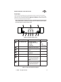
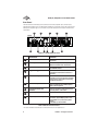
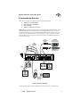
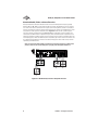
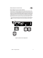
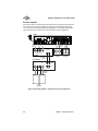
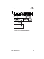
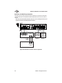
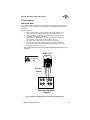
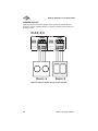
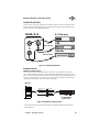
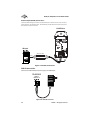
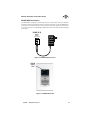
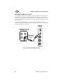
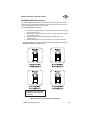
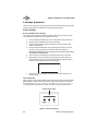
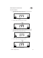
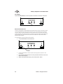
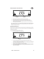
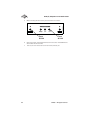
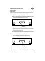
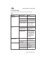
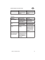
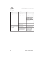
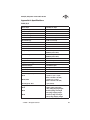
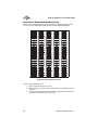
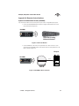
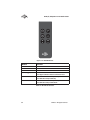
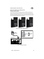
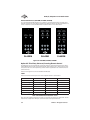
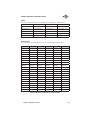
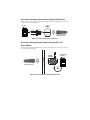
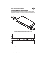
DLA2/DLA4/DLA6
Multi-Room Speaker
Level Audio Router
www.atonhome.com
DLA2/4/6 Speaker Level Audio Router
Safety Information
NOTE: This equipment has been tested and found to comply with the limits for a Class B digital device, pursuant to part 15 of
the FCC Rules. These limits are designed to provide reasonable protection against harmful interference in a residential installation. This equipment generates, uses and can radiate radio frequency energy and, if not in-stalled and used in accordance
with the instructions, may cause harmful interference to radio communications. However, there is no guarantee that interference will not occur in a particular installation.
If this equipment does cause harmful interference to radio or television reception, which can be determined by turning the
equipment off and on, the user is encouraged to try to correct the interference by one or more of the following measures:
•
•
•
•
Reorient or relocate the receiving antenna.
Increase the separation between the equipment and receiver.
Connect the equipment into an outlet on a circuit different from that to which the receiver is connected.
Consult the dealer or an experienced radio/TV technician for help.
CAUTION: Changes or modications not expressly approved by Elan Home Systems could void the user’s authority to operate
the equipment
DLA2/4/6 Power Source
The source of DLA2/4/6 power is the 12VDC wall transformer. A DC-IN jack connects the 12 VDC adapter with the DLA2/4/6
chassis to provide power for the unit. Protect the power supply cord from being walked on or pinched, particularly at plugs,
outlets and the point where they exit from the apparatus.
Severe personal injury and equipment damage can result by not following proper procedures. Use only the 12VDC adapter
designated for the DLA2/4/6.
Caring For the DLA2/4/6
Clean only with a dry soft cloth.
It is important to properly care for your DLA2/4/6 Speaker Selector. Follow these guidelines to ensure your device is preserved
and protected.
•
•
•
Do not expose the DLA2/4/6 to rain, liquids or moisture for an extended period of time.
Do not expose the DLA2/4/6 to temperature extremes.
Do not place any objects on top of the DLA2/4/6 to prevent chassis damage.
Operating Temperatures & Environments
•
•
Operating Temperature: 32-104°F (0-40° C)
Humidity: 0-90%
Precautions
•
•
•
•
•
•
•
Always exercise care when operating the DLA2/4/6 Speaker Selector.
Do not apply excessive amplification.
ATON strongly recommends that you do not add more speakers than recommended.
Do not install near any heat sources such as radiators, heat registers, stoves, or other apparatus (including
amplifiers) that produce heat.
DO NOT use any 12 VDC adapter other than the one provided with the DLA2/4/6.
In the unlikely event that smoke, abnormal noise, or strange odor is present, immediately power the DLA2/4/6
off. Please report the problem to your dealer immediately.
Never attempt to disassemble the DLA2/4/6. You will lose any product warranty on the unit.
Amplier Input 125 Watts per Channel Max
Package Contents
DLA2/4/6 Speaker Selector
12 VDC Power Adapter
Slim-Line IR Remote Control
User/Installation Manual
Quick Install Guide
© 2008 • All rights reserved.
1
DLA2/4/6 Speaker Level Audio Router
Contents
Safety Information ...................................................................... 1
1. Introduction .............................................................................. 3
Features ........................................................................................ 4
ATON DLA2/4/6 Accessories ...................................................... 4
Front Panel ................................................................................... 5
Rear Panel..................................................................................... 6
2. System Design Overview ...................................................... 7
Standard Audio/Video or Stereo Receiver ................................. 8
Zone 2 Output of an A/V or Stereo Receiver.............................. 9
External Amplier ...................................................................... 10
Sub-Zone of a Multi-Room Controller ....................................... 12
3. Connections ........................................................................... 13
AMPLIFIER INPUT....................................................................... 13
SPEAKER OUTPUTS .................................................................... 14
IR EMITTER OUTPUTS ................................................................ 15
ROOM IR INPUTS ........................................................................ 15
DLA Touchpad Connections ...................................................... 16
PWR IN Connection ................................................................... 16
SENSE INPUT Connections .........................................................17
PAGE/DB TRIGGER IN Connections .......................................... 18
IMPEDANCE MATCH DIP Switches ........................................... 19
4. Settings & Operation .......................................................... 20
Volume Settings ........................................................................ 20
Receiver/Ampler Volume Settings ..................................... 20
Volume Status Bar .................................................................. 20
Room Volume Adjustment ...................................................... 21
ALL ON/OFF ................................................................................ 22
Max Turn On Volume .................................................................. 22
PAGE/DB Volume Level.............................................................. 23
Scene Presets ............................................................................. 25
Setting a Scene ....................................................................... 25
Recalling a Scene Preset........................................................ 25
5. Troubleshooting ..................................................................... 26
Appendix A: Specications .................................................... 29
Appendix B: Room Identication Labels ........................... 30
Appendix C: Remote Control Options .................................... 31
Appendix D: REKT Rack Ear Kit (Optional) ........................37
Limited Warranty.......................................................... Back Page
2
©2008 • All rights reserved.
DLA2/4/6 Speaker Level Audio Router
1. Introduction
A Simple Concept Reaches New Heights
The concept is simple and has been around for years - a device that allows you to connect
extra speakers to your existing A/V or stereo receiver. Push a button - your speakers come on.
Push it again - they go off. Turn a knob, and the volume goes up or down. Great concept. Good
exercise, too - especially when your system is located downstairs or on the other side of the
house. Introducing DLA2/4/6 Speaker Level Audio Routers - the most signicant advancement
in the history of speaker selectors!
Patent-Pending Intelligence & Performance
No other speaker selector available today is as smart! With its patent-pending design, The
DLA2/4/6’s pre-congured settings ensure that all speakers receive maximum power at all
times, and that your receiver/amplier isn’t operating below its nominal impedance, which
can cause some very undesirable side effects.
Sound Scenes
DLA2/4/6 lets you create Sound Scenes around your home.Using the front panel of the DLA,
the optional RF remote or IR receivers, you can turn on groups of rooms - or every room. Kid’s
room too loud? Use the optional RF remote to turn the volume down in their room instantly
from the den. At bedtime, turn off the audio throughout the entire house.
A Simple & Affordable Solution
DLA2/4/6 connects directly to your stereo receiver or amplier, making it the affordable way
to add up to 6 more rooms of music to your system. Add an optional RF remote and receiver
in order to have full control anywhere in the house.
Figure 1-1 Front Panel
© 2008 • All rights reserved.
3
DLA2/4/6 Speaker Level Audio Router
Features
•
DLA (Dynamic Level Adjustment) Technology delivers maximum
adjustable volume levels to each room while protecting your
amplier from damage (patent-pending).
•
Adds 2, 4, or 6 additional pairs of speakers to your home
theater/stereo receiver or amplier.
•
Programmable “Scene” command for one-touch recall of your
favorite system settings.
•
One-touch “All On” command turns audio on in all rooms.
•
One-touch “All Off” command turns audio off in all rooms.
•
Room Identication Labels with adhesive backing included for
easy Front Panel Room Identication
•
Optional RF Remote controls volume levels independently for
each room from inside or outside your home (up to 200 ft. range)
•
Optional wired DLA Touchpad (DLATP) controls volume, mute
and room/system power from an individual room. DLATP also
includes a built-in IR Receiver.
•
IR Remote included
•
Quick Install Guide included for fast setup
•
2 Year Limited Warranty
ATON DLA2/4/6 Accessories
IR EmittersPlasma-Friendly IR Receivers
RF Remote & Receiver Kit
RF Remote Only
Rack Ear Kit (DLA4 & DLA6 only)
DLATP DLA Touchpad Controller
Replacement 12VDC/2.1A Power Supply
In-Wall, In-Ceiling, Outdoor &
Home Theater Speakers
Note: For more information and purchase options, visit our website at:
www.atonhome.com.
4
©2008 • All rights reserved.
DLA2/4/6 Speaker Level Audio Router
Front Panel
The front panel of the DLA2/4/6 has multiple selector buttons to access rooms and control
power and volume states. Blue LEDs display Volume level and Room On status, while red LEDs
show that a room is selected for adjustment. Figure 1-2 and Table 1-1 provide descriptions and
locations of Front Panel controls and indicators.
Note: This manual will consistently show images of the DLA2 Two Room Speaker Selector.
DLA4 and DLA6 models are identical in all respects but have additional Speaker Outputs,
Room Select Buttons and Room Indicator LEDs.
.
2
1
1
ROOM 2
ROOM 1
3
4
5
6
7
4
3
Figure 1-2: DLA2/4/6 Front Panel
Indicator/Button
Function
LED
1
Room Indicator LED
Room ON - Selected
Room ON - NOT Selected
Room OFF
Room Muted
Red
Blue
No LED
Blue (Blinking)
2
Volume Indicator
Shows Volume Level for Selected Room- Level 1 to 11
Blue
3
Room Label Location
Place Label to Identify
Rooms
4
Room Select
Selects Room for
Adjustment
5
All ON/All OFF Button
Turns All Rooms ON or OFF
6
VOL -
Decreases Volume of Selected Room by One Step-Press
and Hold to Ramp Volume
Down
7
VOL +
Increases Volume of Selected Room by One Step-Press
and Hold to Ramp Volume
Up
Table 1-1: Front Panel Indicators/Buttons
© 2008 • All rights reserved.
5
DLA2/4/6 Speaker Level Audio Router
Rear Panel
The Rear Panel of the DLA2/4/6 has connections for Power, Amplier Input, Sense Inputs,
page/Doorbell Trigger Inputs, the RF Receiver (ATON Port), IR Emitter Outputs, IR receiver Inputs
and Speaker Outputs. Figure 1-3 and Table 1-2 provide description and location of Rear Panel
connections.
8
9
7
6
6
DLA2
PATENT
PENDING
AMPLIFIER
IP
IR EMITTER OUTPUTS
SENSE
INPUT
PWR IN
12VDC / 2.1A
RF
INPUT
IMPEDANCE
MATCH
9VDC / 100mA
PA E
RI I
CLASS 2 WIRING
1
3
2
4
8
8
4
4
1
5
5
Figure 1-3 : DLA2/4/6 Rear Panel
Connector
Function
1
12 VDC Power Connector
Connector for +12VDC/2.1A (PS3) Power
Transformer
2
Sense Input Connector
Connector for optional +12 VDC/200mA
(PS2) Sense Status Power Transformer
3
IR Emitter Outputs
3.5mm Mono Mini Jack Connectors for Use
With ATON IR Emitters
4
Page/DB Trigger
3.5 mm. Stereo Mini-Jack Connector for use
with ELAN Communication Controllers or
equivalent
5
IR Receiver Inputs
Flip Lock Connectors for IR receivers or DLA
Touchpads. IR receivers allow for individual
room control or system-wide control using
DLA discrete IR codes.*
6
Speaker Outputs
4-position Fliplock Connectors for 16
Gauge, 4 Conductor (16/4 AWG) Speaker
Leads to Room Speakers
7
Impedance Match DIP
Switches
Select The Impedance Value Of the Amplier And Speakers, 4 Or 8 Ohms
8
ATON Port
Connects to Optional RF Receiver
9
Amplier/Receiver Input
4-position Fliplock Connector for 16 Gauge,
4 Conductor (16/4 AWG) Speaker Leads
From Amplier or A/V Receiver Speaker
Outputs
• 125 Watts per Channel Max
Table 1-2: Rear Panel Connectors
* IR codes available for download at: www.atonhome.com. See Appendix C-3.
6
©2008 • All rights reserved.
DLA2/4/6 Speaker Level Audio Router
2. System Design Overview
There are four typical system applications when installing the DLA2/4/6:
1.
2.
3.
4.
Standard A/V or Stereo Receiver
Zone 2 Output of an A/V Receiver
External Amplier
Sub-Zone of a Multi-Room Controller
Figure 2-1 shows a DLA2 connected to an A/V receiver with optional ATON accessories including optional AIR3 IR Receivers, AIE2 IR Emitters and a DLA2RKT RF remote Kit. This system
is capable of house-wide control of the DLA2 through the RF Kit as well as Room 1 and Room
2 control using the included IR Remote. A universal remote or source remote can be used to
control the DLA 2/4/6* as well as the equipment connected to the IR EMITTER OUTPUTS for
even more convenience.
Included IR
Remote Control
(Controls DLA2/4/6)
AIR3
IR Receivers
(Optional)
A/V Receiver
AIE2
IR Emitters
(Optional)
Room 1
DVD
Room 2
Universal/Source
IR Remote Control
Satellite
DLA2
AMPLIFIER
INPUT
PATENT
PENDING
IR EMITTER OUTPUTS
SENSE
INPUT
PWR IN
12VDC / 2.1A
RF
INPUT
IMPEDANCE
MATCH
9VDC / 100mA
PAGE/DB
TRIG IN
CLASS 2 WIRING
8
8
4
4
1
16/4
Speaker
Cables
R
L
16/4
Speaker
Cables
L
R
+
-
OUT
OUT
A/V Receiver
-
MUTE
+
VOL
SCENE
ALL
ON
ROOM 1
Main
Speakers
Room 2
Speakers
VOL
Room 1
Speakers
ROOM 2
RF
Receiver
(Optional)
ALL
OFF
16/4
Speaker
Cables
DLA2RKT
RF Remote Kit
(Optional)
Figure 2-1: System Overview
* DLA discrete IR codes available for download at: www.atonhome.com. See Appendix C-3.
© 2008 • All rights reserved.
7
DLA2/4/6 Speaker Level Audio Router
Standard Audio/Video or Stereo Receiver
Most A/V Receivers and Stereo Receivers have two sets of Main Speaker Outputs (typically
labelled “A” and “B”. While it is certainly possible to connect the DLA2/4/6 to the “A” outputs,
it is much more useful to connect the “A” outputs to the main speakers (stereo or surround) in
the room in which the receiver is located and connect the “B” outputs to the DLA2/4/6 in order
to expand the audio system to additional areas. Figure 2-2 shows the “B” speaker outputs
of an A/V receiver connected to to the AMPLIFIER INPUT of the DLA2. A pair of speakers are
connected to the DLA2’s Room 1 Speaker Outputs, while an additional pair of speakers is connected to the Room 2 Speaker Outputs. In this scenario, the A/V receiver’s speakers play in the
main listening area, while two additional pairs of speakers play in other areas of the home. This
is a single-source application: all areas of the house will play the same audio source, but with
separately controlled volume.
Note: For best audio quality, ATON recommends that Surround Sound and/or DSP modes
(Concert, Hall, Jazz, etc.) be disabled prior to playing audio through the DLA2/4/6.
DLA2
AMPLIFIER
INPUT
PATENT
PENDING
IR EMITTER OUTPUTS
SENSE
INPUT
PWR IN
12VDC / 2.1A
RF
INPUT
IMPEDANCE
MATCH
9VDC / 100mA
PAGE/DB
TRIG IN
CLASS 2 WIRING
8
8
4
4
1
16/4
Speaker
Cables
R
L
16/4
Speaker
Cables
R
L
+
-
A
B
A/V Receiver
Room 1
Speakers
(B)
Room 2
Speakers
(B)
Main
Speakers
(A)
Figure 2-2: DLA2 with A/V Receiver Output B Overview
8
©2008 • All rights reserved.
DLA2/4/6 Speaker Level Audio Router
Zone 2 Output of an A/V or Stereo Receiver
Certain A/V Receivers and Stereo Receivers have a Zone 2 feature that allows them to play
a seperate source to a second zone. Figure 2-3 shows the Zone 2 speaker outputs of an A/V
receiver connected to to the AMPLIFIER INPUT of the DLA2. Like the previous example, a pair
of speakers are connected to the DLA2s Room 1 Speaker Outputs, while an additional pair of
speakers is connected to the Room 2 Speaker Outputs. This application allows the A/V receiver’s Main speakers to play in the room in which the receiver is located, while two additional
pairs of speakers play in other areas of the home. This is a multi-source application: the Main
speakers may play one source, while Zone 2 (the DLA2 locations) plays a different source.
Note: Set the Zone 2 volume level to the point where it achieves the maximum listenable
level (prior to distortion). The DLA2/4/6’s volume level will adjust up to this maximum
level.
DLA2
AMPLIFIER
INPUT
PATENT
PENDING
IR EMITTER OUTPUTS
SENSE
INPUT
PWR IN
12VDC / 2.1A
RF
INPUT
IMPEDANCE
MATCH
9VDC / 100mA
PAGE/DB
TRIG IN
CLASS 2 WIRING
8
8
4
4
1
16/4
Speaker
Cables
L
R
16/4
Speaker
Cables
L
R
+
-
ZONE 1
ZONE 2
A/V Receiver
Room 1
Speakers
(Zone 2)
Room 2
Speakers
(Zone 2)
Main
Speakers
(Zone 1)
Figure 2-3: A/V Receiver Zone 2 Application
© 2008 • All rights reserved.
9
DLA2/4/6 Speaker Level Audio Router
External Amplier
Some systems utilize an external amplier for speakers that are connected to the DLA2/4/6.
In A/V receiver or stereo receiver applications, a line-level output (Tape Loop, Monitor Out,
etc.) is connected to the external amplier (See Figure 2-4). In a Pre-Amp/Processor-based
system, the Pre-Amp is connected to the external amplier as shown in Figure 2-5.
DLA2
AMPLIFIER
INPUT
PATENT
PENDING
IR EMITTER OUTPUTS
SENSE
INPUT
PWR IN
12VDC / 2.1A
RF
INPUT
IMPEDANCE
MATCH
9VDC / 100mA
PAGE/DB
TRIG IN
CLASS 2 WIRING
8
8
4
4
1
16/4
Speaker
Cables
16/4
Speaker
Cables
+
-
-
L
+
R
Line-Level
Inputs
L
R
Speaker Outputs
Amplifier
A/V Receiver
Room 1
Speakers
RCA
Interconnect
Cables
Speaker Outputs
+
L
-
R
-
Room 2
Speakers
OUT
+
L
R
IN
TAPE
LOOP
Speaker
Cables
Main
Speakers
Figure 2-4: External Amplier - A/V Receiver Tape Loop Application
10
©2008 • All rights reserved.
DLA2/4/6 Speaker Level Audio Router
DLA2
AMPLIFIER
INPUT
PATENT
PENDING
IR EMITTER OUTPUTS
SENSE
INPUT
PWR IN
12VDC / 2.1A
RF
INPUT
IMPEDANCE
MATCH
9VDC / 100mA
PAGE/DB
TRIG IN
CLASS 2 WIRING
8
8
4
4
1
16/4
Speaker
Cables
+
16/4
Speaker
Cables
L
-
+
R
Line-Level
Inputs
L
R
Speaker Outputs
Amplifier
RCA
Interconnect
Cables
Room 1
Speakers
Room 2
Speakers
L
R
Line-Level
Outputs
Pre-Amp/Processor
Figure 2-5: Processor/Pre-Amp - Amplier Application
© 2008 • All rights reserved.
11
DLA2/4/6 Speaker Level Audio Router
Sub-Zone of a Multi-Room Controller
The DLA2/4/6 can be used to expand the number of speakers in a sub-zone of a multi-room
controller-based system. This application provides independent control of each area within a
sub-zone.
Note: The source will be identical between all areas of a zone, including all sub-zones and
speakers connected to the DLA2/4/6 Speaker Selector.
DLA2
AMPLIFIER
INPUT
PATENT
PENDING
IR EMITTER OUTPUTS
SENSE
INPUT
PWR IN
12VDC / 2.1A
RF
INPUT
IMPEDANCE
MATCH
9VDC / 100mA
PAGE/DB
TRIG IN
CLASS 2 WIRING
8
8
4
4
1
16/4
Speaker
Cables
+
16/4
Speaker
Cables
L
-
+
Line-Level
Inputs
L
R
R
Speaker Outputs
Amplifier
RCA
Interconnect
Cables
Room 1
Speakers
Room 2
Speakers
L
R
Zone Pre-amp
Outputs
Multi-Room Controller
Figure 2-6: Multi-Room Controller Sub-Zone Application
12
©2008 • All rights reserved.
DLA2/4/6 Speaker Level Audio Router
3. Connections
AMPLIFIER INPUT
Use 16 AWG stranded copper speaker wire to connect from a speaker level output of an A/V
receiver, stereo receiver, or amplifer. Turn power for the output device OFF before making
connections.
To make connections:
1.
2.
3.
4.
5.
Cut the ends of the wire to length, allowing some free play (about 6 inches
of slack) to allow for movement when physically connecting the wire.
Using wire strippers, remove 3/8 inch of insulation, then twist the wire to
ensure that no stray strands are evident.
Dene positive (+) and negative (-) at the amplier end and the DLA2/4/6
end of the wire run and use the same conductor on each end.
Lift up each ip-lock connector until it is locked in the up position.
Place the bare lead from each speaker wire from the receiver/amplier
into the holes of the Amplier Inputs terminal of the DLA2/4/6, maintaining
the polarity of each lead (+ to +, - to -).
Note: To avoid damage to the receiver/ampler, DO NOT allow speaker leads to touch
each other.
DLA2/4/6
AMPLIFIER
INPUT
125 Watts
per Channel
Max
CLASS 2 WIRING
Speaker
Cables
R
L
R
L
+
-
A
B
Receiver/Amplifier
Output
Figure 3-1: Receiver/Amplier Output to DLA2/4/6 Amplier Input
© 2008 • All rights reserved.
13
DLA2/4/6 Speaker Level Audio Router
SPEAKER OUTPUTS
Follow the procedures outlined in the previous section to connect the Speaker Outputs to
the Room 1 and Room 2 speakers. Make sure to match the impedance of the speakers and
ampliers as noted.
DLA2/4/6
1
Room 1
Room 2
Figure 3-2: DLA2/4/6 Speaker Outputs to Room Speakers
14
©2008 • All rights reserved.
DLA2/4/6 Speaker Level Audio Router
IR EMITTER OUTPUTS
Three IR Emitter outputs are provided for controlling components such as A/V Receivers, DVD
Players, CD Players, Digital Music Servers, etc. Any IR signal received by a Room IR INPUT will
be sent out of ALL of the IR EMITTER OUTPUTS.
DLA2/4/6
A/V Receiver
IR EMITTER OUTPUTS
IR
Mini-Emitters
IR
Mini-Emitters
DVD
Satellite
Figure 3-3: IR EMITTER OUTPUTS
ROOM IR INPUTS
IR Receiver Connections
The DLA2/4/6 features an IR Receiver Input for each room. To facilitate IR control of each
room, connect a standard IR receiver (such as ATON’s AIR1, AIR3, AIR5 and/or AIR6) to these
inputs as shown in Figure 3-4. Each IR receiver will send IR signals to the DLA2/4/6 and control
the room it is connected to.* Cat-5 cable can be used to extend the length of the IR receiver’s
connecting cable. Provisions exist for IR, Ground, and Voltage.
Cat-5
Wh/Green (+12V)
Brown (G)
Wh/Blue (IR)
Splice to Cat-5 Wire
IR Input
Red (+12V)
Black (G)
Yellow (N/C)
White (IR)
AIR3
(or other ATON
IR Receiver)
Figure 3-4: IR Receiver Connections
* System-wide control from one IR receiver location is possible using DLA discrete IR codes.
See Appendix C-3.
© 2008 • All rights reserved.
15
DLA2/4/6 Speaker Level Audio Router
DLA Touchpad (DLATP) Connections
Connect a DLATP using Cat-5 cable to any Room IR Input to control volume, mute and room/
system power for an individual room. The DLATP also provides Room and Sense Input status
and includes a built-in IR receiver.
DLATP Rear
IR Input
Wh/Green (+12V)
Brown (G)
Orange (Sense)
Cat-5
Wh/Blue (IR)
Figure 3-5: DLATP Connections
PWR IN Connection
Connect the included 12VDC/2.1A power supply to the PWR IN port.
DLA2/4/6
PWR IN
12VDC/2.1A
PS3
12VDC
POWER
SUPPLY
Figure 3-6: PWR IN Connector
16
©2008 • All rights reserved.
DLA2/4/6 Speaker Level Audio Router
SENSE INPUT Connection
The SENSE INPUT is designed to provide power status of a connected A/V receiver on all DLATP
Touchpads. Simply plug an ATON PS2 Power Supply (sold separately) into the DLA SENSE INPUT
connector and into the switched outlet of an A/V receiver as shown in Figure 3-7. Whenever the
A/V receiver is turned on, the SENSE INPUT LED will illuminate on all connected DLA Touchpads
in the system.
DLA2/4/6
SENSE
INPUT
12VDC / 200mA
PS2
12VDC
Power
Supply
Figure 3-7: SENSE INPUT Connector
SENSE
INPUT
LED
Figure 3-8: SENSE INPUT LED
© 2008 • All rights reserved.
17
DLA2/4/6 Speaker Level Audio Router
PAGE/DB TRIGGER IN Connection
The Page/Doorbell Trigger Input (PG/DB TRIG IN) needs to be connected when the DLA2/4/6 is
installed as part of a “sub-zone” of an ELAN® Multi-Room Controller, such as the S8.6 or S12,
which utilizes an ELAN COM2 Communications Controller. This application allows the DLA Room
Outputs to pass an audible tone through the room’s speakers at a preset level when the home’s
doorbell is activated.
To congure the PG/DB TRIGGER IN, simply connect a mono 3.5mm interconnect cable
between the Page/Doorbell Trigger Out of the ELAN Multi-Room Controller and the PG/DB TRIGGER IN of the DLA2/4/6 as shown below.
S8.6
IN
DLA2/4/6
PAGE
TRIGGER
OUT
IR EMITTER OUTPUTS
3.5mm Mono
Interconnect
Cable
PAGE/DB
TRIG IN
MOH OUT
PG IN
PG OUT
Figure 3-9: PAGE/DB TRIG IN Connection
18
©2008 • All rights reserved.
DLA2/4/6 Speaker Level Audio Router
IMPEDANCE MATCH DIP Switches
The IMPEDANCE MATCH DIP Switches are designed to allow various speaker loads to work
safely with variously rated ampliers. Speakers rated between 4 Ohms and 8 Ohms can be
matched with ampliers also rated from 4 to 8 Ohms.
To set IMPEDANCE MATCH DIP Switches:
1.
2.
3.
4.
Determine the average impedance of all connected speakers (listed on the speaker
or in the owner’s manual).
Determine the minimum impedance rating of the amplier (listed on the amplier
or in the owner’s manual).
Set the AMP DIP Switch to the minimum impedance rating listed on the
amplier/receiver.
Set the SPKR DIP Switch to the average impedance of all connected speakers.
Note: Most speakers are 4 or 8 Ohms. In cases where 6 Ohms speakers are used, place
the SPKR DIP Switch in the 4 Ohm position.
Note: When using this setting,
maximum volume is reduced
to 10 steps.
Figure 3-10: Impedance Match DIP Switch Settings
© 2008 • All rights reserved.
19
DLA2/4/6 Speaker Level Audio Router
4. Settings & Operation
Functions of the DLA2/4/6 may be controlled from the Front Panel controls, through optional
IR Receivers connected to the IR INPUTS, or with the optional RF Remote.
Volume Settings
Receiver/Ampler Volume Settings
Prior to setting volume levels of the DLA2/4/6, proper volume level must be set of the Receiver/Amplier. To set proper Receiver/Amplier volume level:
1.
Turn on the Receiver/Amplier and start an audio source (CD Player, Radio, etc.).
2.
Adjust the Receiver/Amplier level to the lowest setting.
3.
Set the Receiver/Amplier to Stereo and disable any surround sound or DSP
modes or “Sound Fields”.
4.
If using a Receiver/Amplier with “A/B” speaker outputs, select the “B” speakers and turn off the “A” speakers for maximum output to the DLA2/4/6.
Note: When the DLA2/4/6 is not in use, turn off the “B” speakers and turn on the
“A” speakers for normal operation.
5.
Turn on one room of the DLA2/4/6 and adjust the volume level to maximum.
6.
While listening to the room turned on in the previous step, slowly adjust the receiver/amplier volume to the loudest level possible without distortion. Make a
note of the receiver/amplier level for future reference.
RECEIVER/AMPLIFIER LEVEL
7.
Turn on each room of the system and adjust the volume of the DLA2/4/6 to a
comfortable level.
Volume Status Bar
The front panel includes a Volume Indicator LED bar with 11 LED’s located above the All On/
Off and Volume -/+ buttons. The Volume Indicator LEDs display the Volume for whichever
Room is selected. When a Room is selected and ONE LED is lit, that room is at minimum volume. When a Room is selected and ALL LEDs are lit, that room is at maximum volume.
Volume Status Bar
Figure 4-1: Volume Status Bar
20
©2008 • All rights reserved.
DLA2/4/6 Speaker Level Audio Router
Room Volume Adjustment
1.
Press the Room 1 Selector Button - the Room 1 Indicator LED will light up RED
(indicating that Room 1 is selected for adjustment).
ROOM 1
ROOM 2
Press
2.
Press VOL - or VOL + until the desired volume is obtained.
Press
OR
ROOM 1
3.
ROOM 2
Press the Room 2 Selector Button - the Room 2 Indicator LED will light up RED
(indicating that Room 2 is selected for adjustment), while the Room 1 Indicator
LED will light up BLUE (indicating that Room 1 is ON).
ROOM 1
ROOM 2
Press
4.
Press VOL - or VOL+ until the desired volume is obtained.
Press
OR
ROOM 1
5.
ROOM 2
Continue this process for each additional Room.
© 2008 • All rights reserved.
21
DLA2/4/6 Speaker Level Audio Router
ALL ON/OFF
Press the ALL ON/OFF Button to turn the speakers in both Room 1 and Room 2 ON or OFF.
ROOM 1
ROOM 2
Press
Max Turn-On Volume Level
In order to guard against unexpected high volume levels when the system is turned on, a Maximum Turn-On Volume Level may be set for each room. If the volume level prior to turning the
room off is lower or equal to the Maximum Turn-On Volume Level, the room will come back on
at the last volume. If the volume level prior to turning the room off is higher than the Maximum
Turn-On Volume Level, the room will come back on at the Maximum Turn-On Volume Level
instead of the last volume.
To set the Maximum Turn-On Volume Level for a Room:
1.
Press the Room Button for the desired room.
ROOM 1
ROOM 2
Press
2.
3.
4.
22
Set the desired Maximum Turn-On Volume Level using the front panel Vol + and
Vol - Buttons.
Press and hold the Room Button on the front panel (Room LED will turn off and all
Volume LED’s will go off).
Without releasing the Room button, press and hold the Vol - Button.
©2008 • All rights reserved.
DLA2/4/6 Speaker Level Audio Router
ROOM 1
ROOM 2
Press
& Hold
5.
6.
7.
8.
Press
& Hold
After 3 seconds the Maximum Turn-On Volume Level is saved.
Room LED and Volume LED’s blink four times (Room LED blinks RED).
The Room will turn back on to the volume level it was set to prior to setting the
Maximum Turn-On Volume Level.
Turn the Room Off, then back On to achieve the Maximum Turn-On Volume Level.
Note: Setting the Maximum Turn-On Volume Level to the highest volume level will essentially
disable Maximum Turn-On Volume (the room will always come back on at the last volume
level prior to turning the room Off).
Page/Doorbell Volume Level
By programming the Page/Doorbell Volume Level for each room of the DLA system, the volume
levels for each of the rooms will jump to their programmed settings when the PAGE/DB INPUT of
the DLA2/4/6 is activated.
To set the Page/Doorbell Volume Levels for a room:
1.
Press the Room Button for the desired room.
ROOM 1
ROOM 2
Press
2.
3.
4.
Set the desired Page/Doorbell Volume Level using the front panel Vol + and
Vol - Buttons. Note: Any room whose LED is not lit (red or blue) will be considered Off
when setting the Page/Doorbell volume level.
Initiate a Page or Doorbell signal from the ELAN COM2 Communications Controller to
check the volume setting. Adjust the volume as required.
Press and hold the Room Button on the front panel (Room LED will turn off and all
Volume LED’s will go off).
© 2008 • All rights reserved.
23
DLA2/4/6 Speaker Level Audio Router
5.
Without releasing the Room button, press and hold the Vol + Button.
ROOM 1
ROOM 2
Press
& Hold
6.
7.
24
Press
& Hold
After three seconds, the Page/Doorbell Volume Level is saved. The ROOM LED and
Volume LEDs will blink four times
Once set, the room reverts back to the volume level previously set.
©2008 • All rights reserved.
DLA2/4/6 Speaker Level Audio Router
Scene Presets
Setting a Scene
A Scene Preset allows the volume level for each room to be saved and then recalled at any
time with the press of a button.
To set a Scene Preset:
1.
Set the volume in each room to the desired level.
Note: Any room whose LED is not lit (red or blue) will be considered OFF when setting
a Scene.
2. Press and hold the ALL ON/OFF Button for three seconds.
ROOM 1
ROOM 2
Press
& Hold
3.
Once the Scene Preset has been saved, the Room LEDs for the rooms included in
the Scene Preset will blink on and off four times and the system will return to the
levels prior to setting the Scene Preset.
Note: If a Room LED does NOT blink, it will not be activated when a Scene is selected.
Recalling a Scene Preset
The Scene Preset values for each room can be recalled in two ways:
1.
2.
Press the Scene Button on the IR Remote (or optional RF Remote).
Press the Vol + and Vol - simultaneously for one second on the front
of the unit.
ROOM 1
ROOM 2
Press
& Hold
Note: Scene Presets override Default Volume Levels.
Note: Room LEDs are BLUE for any Room with Volume greater than 0 and OFF for any
Room with Volume of 0.
© 2008 • All rights reserved.
25
DLA2/4/6 Speaker Level Audio Router
5. Troubleshooting
Table 5-1 provides troubleshooting information for the DLA2/4/6 Speaker Selector.
Audio
Symptom
Possible Cause
Solution
No audio present in a
specic room
1. Source not playing.
Press Play, turn ON, etc.
2. Room not selected
Select Room on Front
Panel or from RF Remote
3. Room Output volume
turned all the way down
Increase volume.
4. Speakers in room
miswired or defective
a. Test known good
speaker at back panel
speaker connector
b. Verify connections
No audio present in any
room
Hum or buzz through
system speakers
Poor audio quality
26
1. See above
Perform steps above
2. Amplier/Receiver
turned OFF or down
Turn On Amplier/Receiver or increase
volume
3. Amplier or Receiver
in protection mode
Find cause of amplier’s
protection mode and correct. Miswired speakers
most likely cause. Verify
that the impedance levels of the amp and
speaker are not lower
than 8 Ohms.
1. Ground loop
Ensure proper grounding using a three prong
grounded AC outlet.
2. Receiver/Amplier
level too high
Reduce level
1. Clipping or distortion
Reduce Receiver/Ampler level
2. Speakers out of phase
Carefully check polarity
of each speaker
3. Incorrect assignment
of left/right source RCA
cables or speaker cables
Isolate to source or room
and correct
©2008 • All rights reserved.
DLA2/4/6 Speaker Level Audio Router
Symptom
Possible Cause
Solution
Volume only ramps to 10
4 Ohm Speaker connected to 8 Ohm-rated
amplier.
Normal operation. Functions this way to protect
amplier.
Symptom
Possible Cause
Solution
No source control in a
Room from IR port
1. Wiring: IR signal not
reaching Room input.
Check Room IR receiver
and verify wiring.
2. Remote Control batteries are dead.
Replace batteries.
IR Control
No source control in any
Room.
1. See above.
Perform steps above.
2. Source IR Emitters
unplugged or defective.
Reconnect or test with
known good IR Emitters.
Intermittant source
control.
Mild to moderate IR
Flooding.
Check IR indicator on
front panel. If it ickers,
IR ooding is indicated.
Check any IR receivers
that may be receiving
ambiant light or plasma
TV noise.
Room appears to be on
and selected but unabled
to be controlled using
front panel buttons.
Extreme IR ooding.The
IR indicator will be solid
red when the room is off,
solid off when the room
is on, or solid purple
when the room is on and
unselected.
Perform steps above.
© 2008 • All rights reserved.
27
DLA2/4/6 Speaker Level Audio Router
RF Control
Symptom
Possible Cause
No control of DLA2/4/6 1. Wiring: Signals from
from optional RF Remote RF Receiver Base not
reaching DLA2/4/6
Solution
Check RF Receiver Base
connection to DLA2/4/6
and verify connectivity
Check Room 1 indicator
on front of DLA2/4/6
by sending a command
from the RF remote. If
the indicator LED ashes
red, the RF signal is being received.
Intermittent control of
DLA2/4/6 from optional
RF Remote
28
2. Remote Control batteries are dead
Replace batteries
1. Position of Receiver
base not optimal
Move Receiver base to
nd optimum placement.
2. Radio Frequency deCheck for other devices
vices operating nearby in in the home or neighsame frequency band
boring dwellings and
relocate if possible
©2008 • All rights reserved.
DLA2/4/6 Speaker Level Audio Router
Appendix A: Specifications
DLA2/4/6
Power Input
+12 VDC, 2.1 Amps
Amplier Impedance
4 - 8 Ohms
Speaker Impedance
4 - 8 Ohms
Frequency Response
20 HZ to 20 kHZ +/- 1 dB
Power Handling
Per Channel: 125 Watts RMS
Max Attenuation
-56 dB @ Last Step
Dynamic Range
43 dB over 12 steps
THD
< 1%
Connections
Power
2.1 mm Jack
Amplier Input
4 Position Flip-lock Connector
(16AWG Speaker Wire)
Speaker Output
4 Position Flip-lock Connector
(16AWG Speaker Wire)
Sense Inputs
2.1mm Jack
IR Input
4 Position Flip-lock Connector
Page/Doorbell Trigger In
3.5mm Mono Jack
IR Emitter Output
3.5 mm Mono jack
RF Input (ATON Port)
RJ-11 jack
Dimensions
H x W x D (w/ feet)
DLA2
2 3/16" x 8 1/2" x 7 5/8"
(5.6cm x 21.6cm x 19.4cm)
DLA4/DLA6
2 3/16" x 17" x 8 5/8"
(5.6cm x 43.2cm x 21.9cm)
Unit Height w/ Feet
1 3/4" (4.5cm)
Weight
DLA2
4.95lbs (2.3kg) unit weight
5.7lbs (2.6kg) shipping weight
DLA4
10.15lbs (4.6kg) unit weight
11lbs (5kg) shipping weight
DLA6
12.15lbs (5.5kg) unit weight
13lbs (5.9kg) shipping weight
© 2008 • All rights reserved.
29
DLA2/4/6 Speaker Level Audio Router
Appendix B: Room Identification Labels
Use the included Room Identication Labels to customize the DLA2/4/6 front panel. Place
the labels in the oval Room Label Locations located below the Room Select Buttons.
Figure B:1 Room Identication Labels
To place a Room Identication Label:
1.
2.
3.
30
Choose an appropriate label for the room.
Make sure that the oval Room Label Location on the face of the DLA2/4/6 is clean
and oil free.
Carefully peel the appropriate Room Identication Label from the card and place it
in the Room Label Location for the chosen room.
©2008 • All rights reserved.
DLA2/4/6 Speaker Level Audio Router
Appendix C: Remote Control Options
Option #1: DLA Slimline Remote (DLAIRM)
Any combination of DLA remote control options may be used on a single DLA2/4/6 system.
Use the included DLAIRM IR Remote Control to program DLA IR codes into a thirdparty universal/learning remote.
DLAIRM
Universal/Learning
IR Remote Control
Figure C-1: Universal Remote
Use the DLAIRM as an IR remote for any individual room. Each room that is to be
controlled with the DLAIRM requires an IR receiver wired into that specic room’s IR
Input as shown in Figure C-2.
IR Input
DLAIRM
Cat-5
AIR5
Figure C-2: DLAIRM as Room Controller
© 2008 • All rights reserved.
31
DLA2/4/6 Speaker Level Audio Router
Figure C-3 : DLAIRM Remote
Button
Function
ALL ON
Turns all Rooms ON
ALL OFF
Turns all Rooms OFF
SCENE
Places Rooms into Scene Preset Mode
MUTE (Toggle)
Press to Reduce Volume of Room to 0
Press Again to Restore Volume to Previous Level
Volume +
Increases Volume of Room by One Step
Press & Hold to Ramp Volume Up
Volume -
Decreases Volume of Room by One Step
Press & Hold to Ramp Volume Down
Table C-1: IR Remote Functions
32
©2008 • All rights reserved.
DLA2/4/6 Speaker Level Audio Router
Option #2: DLA RF Remote & Receiver Kit
DLA2RKT, DLA4RKT, DLA6RKT
The DLA RF Remote & Receiver Kits (DLA2RKT, DLA4RKT and DLA6RKT) use Radio Frequencies (RF) to control the DLA system from anywhere in the home, up to 200 feet away. It is not
necessary to point the remote at the main unit in order for it to function. Simply connect the RF
Receiver base to the ATON Port on the rear of the unit as shown in Figure C-5. Place the receiver
in a convenient location; preferably as high as possible. The RF Receiver Base utilizes mounting
holes to mount the unit to a wall, cabinet or other surface.
Figure C-4: DLA2RKT, DLA4RKT, DLA6RKT
RF
Receiver
X
Mounting
Bracket
Tabs
Mounting
Holes
X
Mounting
Bracket
RJ-11
Plug
DLA2/4/6
PATENT
PENDING
PWR IN
12VDC / 2.1A
AMPLIFIER
INPUT
SENSE
INPUT
RF
INPUT
Rear View
IR EMITTER
OUTPUTS
9VDC/100mA
Figure C-5: RF Base Connection
© 2008 • All rights reserved.
33
DLA2/4/6 Speaker Level Audio Router
Additional RF Remotes (DLA2RM, DLA4RM, DLA6RM)
Up to six additional DLA RF Remotes can be added to an exisiting RF receiver, providing convenient RF control for the entire family. Programming additional remotes can be accomplished in a
matter of seconds. See the DLA RF Remote Instruction Sheet for more information.
ROOM 1
ROOM 2
ROOM 1
ROOM 2
1
2
1
2
ROOM 1
ROOM 2
ROOM 3
ROOM 4
ROOM 3
ROOM 4
1
2
3
4
3
4
ROOM 5
ROOM 6
5
6
ALL
ON
SCENE
VOL
+
ALL
ON
SCENE
VOL
+
ALL
ON
SCENE
VOL
+
ALL
OFF
MUTE
–
VOL
ALL
OFF
MUTE
–
VOL
ALL
OFF
MUTE
–
VOL
DLA2RM
DLA4RM
DLA6RM
Figure C-6: DLA2RM, DLA4RM, DLA6RM
Option #3: Third-Party Universal/Learning Remote Control
The DLA2/4/6 can be controlled with virtually any brand of universal/learning remote by downloading DLA discrete IR codes from ATON’s website; www.atonhome.com. These codes can then
be imported into most universal/learning remote software applications and transferred into the
universal remote.
Tables C-2 through C-4 list all of the available DLA IR codes.
LOCAL
These commands control only the room that a single IR receiver is connected to.
Local Power On
FOB Volume Up
Local Volume = 1
Local Volume = 9
Local Power Off
FOB Volume Down
Local Volume = 2
Local Volume = 10
Local Power Toggle
FOB Mute Toggle
Local Volume = 3
Local Volume = 11
Local Set Default
FOB All On
Local Volume = 4
Local Set Override
FOB All Off
Local Volume = 5
Local Mute On
FOB Scene
Local Volume = 6
Local Mute Off
Local Volume = 7
Local Mute Toggle
Local Volume = 8
Table C-2: DLA Discrete IR Code Set - Local
Note: Local Commands control only one room at a time. Do not atttempt to “daisy chain” one IR
receiver into multiple Room IR Inputs as this will cause erratic system behavior.
34
©2008 • All rights reserved.
DLA2/4/6 Speaker Level Audio Router
Global
These commands control all rooms simultaneously from any ONE Room IR Receiver Input.
Global Volume Up
Global Set Override
Global Volume = 1
Global Volume = 7
Global Volume Down
Global Mute On
Global Volume = 2
Global Volume = 8
Global Power On
Global Mute Off
Global Volume = 3
Global Volume = 9
Global Power Off
Global Mute Toggle
Global Volume = 4
Global Volume = 10
Global Power Toggle
Global Store Preset
Global Volume = 5
Global Volume = 11
Global Set Default
Global Recall Reset
Global Volume = 6
Table C-3: DLA Discrete IR Code Set - Global
Room Specic
These commands control a specic Room (1-6), from any ONE Room IR Receiver Input.
Room 1
Room 2
Room 3
Room 4
Room 5
Room 6
Volume Up
Volume Up
Volume Up
Volume Up
Volume Up
Volume Up
Volume Down
Volume Down
Volume Down
Volume Down
Volume Down
Volume Down
Power On
Power On
Power On
Power On
Power On
Power On
Power Off
Power Off
Power Off
Power Off
Power Off
Power Off
Power Toggle
Power Toggle
Power Toggle
Power Toggle
Power Toggle
Power Toggle
Set Default
Set Default
Set Default
Set Default
Set Default
Set Default
Set Override
Set Override
Set Override
Set Override
Set Override
Set Override
Mute On
Mute On
Mute On
Mute On
Mute On
Mute On
Mute Off
Mute Off
Mute Off
Mute Off
Mute Off
Mute Off
Mute Toggle
Mute Toggle
Mute Toggle
Mute Toggle
Mute Toggle
Mute Toggle
Volume = 1
Volume = 1
Volume = 1
Volume = 1
Volume = 1
Volume = 1
Volume = 2
Volume = 2
Volume = 2
Volume = 2
Volume = 2
Volume = 2
Volume = 3
Volume = 3
Volume = 3
Volume = 3
Volume = 3
Volume = 3
Volume = 4
Volume = 4
Volume = 4
Volume = 4
Volume = 4
Volume = 4
Volume = 5
Volume = 5
Volume = 5
Volume = 5
Volume = 5
Volume = 5
Volume = 6
Volume = 6
Volume = 6
Volume = 6
Volume = 6
Volume = 6
Volume = 7
Volume = 7
Volume = 7
Volume = 7
Volume = 7
Volume = 7
Volume = 8
Volume = 8
Volume = 8
Volume = 8
Volume = 8
Volume = 8
Volume = 9
Volume = 9
Volume = 9
Volume = 9
Volume = 9
Volume = 9
Volume = 10
Volume = 10
Volume = 10
Volume = 10
Volume = 10
Volume = 10
Volume = 11
Volume = 11
Volume = 11
Volume = 11
Volume = 11
Volume = 11
Table C-4: DLA Discrete IR Code Set - Room Specic
© 2008 • All rights reserved.
35
Universal/Learning Remote Control Using an IR Receiver
Connect an IR receiver such as an ATON AIR5 to a Room IR Input as shown below to control any
or all rooms from a single location.
IR Input
Cat-5
Wh/Gr (+12V)
Brown (G)
Wh/Bl (IR)
Splice to Cat-5 Wire
AIR5
Red (+12V)
Black (G)
Yellow (N/C)
White (IR)
Universal/Learning
IR Remote Control
Figure C-7: Universal Remote w/ IR Receiver
Universal/Learning Remote Control Using an RF-to-IR
Base Station
Connect a third party RF-to-IR base station to any one Room IR Input to control any or all rooms
from any location in the house.
IR Input
RF DATA
USB
GND
SENSE
PWR
SIGNAL
STATUS
+12VDC
Universal/Learning
IR Remote Control
W
A
L
L
DLA2/4/6
RF-to-IR
Converter
3.5mm
Mono
Interconnect
Cable
Figure C-8: Universal Remote w/ RF to IR Converter
DLA2/4/6 Speaker Level Audio Router
Appendix D: REKT Rack Ear Kit (Optional)
Use the optional REKT Rack Ear Kit to mount the DLA4 or DLA6 into a standard equipment
rack. The DLA2 is NOT compatible with the rack ear Kit. Simply use the included screws to attach each rack ear to the side of the DLA4 or DLA6 as shown in Figure D-1. Use Rack screws
(not included) to attach the assembled unit to the equipment rack as shown in Figure D-2.
Figure D-1: REKT Rack Ear Kit-Mounting Rack Ears to Unit
Figure D-2: REKT Rack Ear Kit-Mounting Unit to Rack
© 2008 • All rights reserved.
37
DLA2/4/6 Speaker Level Audio Router
Notes:
38
©2008 • All rights reserved.
DLA2/4/6 Speaker Level Audio Router
Limited Warranty
ATON warrants the DLA2, DLA4 and DLA6 Speaker Selectors to be free from defects in
materials and workmanship for the period of two years (2 years) from date of purchase. If
within the applicable warranty period above purchaser discovers that such item was not as
warranted above and promptly contacts ATON at (859)-422-7137 or [email protected],
ATON shall repair or replace the item at the company’s option. This warranty shall not apply
(a) to equipment not manufactured by ATON, (b) to equipment which is not installed to ATON’s
specications, (c) to equipment which shall have been repaired or altered by others than
ATON, (d) to equipment which shall have been subjected to negligence, accident, or damage by circumstances beyond ATON’s control, including, but not limited to, lightning, ood,
electrical surge, tornado, earthquake, or other catastrophic events beyond ATON’s control, or
to improper operation, maintenance or storage, or to other than normal use of service. With
respect to equipment sold by, but not manufactured by ATON, the warranty obligations of
ATON in all respects conform to the warranty actually extended to ATON by its supplier. The
foregoing warranties do not cover reimbursement for labor, transportation, removal, installation or other expenses which may be incurred in connection with repair or replacement.
Except as may be expressly provided and authorized in writing by ATON, ATON shall not be subject to any other obligations or liabilities whatsoever with respect to equipment manufactured
by ATON or services rendered by ATON.
THE FOREGOING WARRANTIES ARE EXCLUSIVE AND IN LIEU OF ALL OTHER EXPRESSED AND
IMPLIED WARRANTIES EXCEPT WARRANTIES OF TITLE, INCLUDING BUT NOT LIMITED TO
IMPLIED WARRANTIES OF MERCHANTABILITY AND FITNESS FOR A PARTICULAR PURPOSE.
ATTENTION: TO OUR VALUED CONSUMERS
Valid proof of purchase is required for all warranty services. Warranty service requests made
without proof of date of purchase will be denied. Please keep the original sales receipt for
your records and send a copy to request warranty service.
1300 East New Circle Road
Lexington, KY 40505
www.atonhome.com
or
[email protected]
40
©2008 • All rights reserved.