1
251
®
FABRICATOR
MIG WELDING MACHINE
Art # A-08561
Operating Manual
Revision: AB
Operating Features:
Issue Date: August 22, 2008
208
V
230
V
Manual No.: 0-5098
60 HZ
!
WARNINGS
Read and understand this entire Manual and your employer’s safety practices before installing,
operating, or servicing the equipment.
While the information contained in this Manual represents the Manufacturer's best judgement,
the Manufacturer assumes no liability for its use.
Fabricator 251 MIG Welding Machine
Instruction Manual Number 0-5098 for:
Package System Part Number 100048DVN
Power Source Part Number 871987
Published by:
Valley National Gases LLC
67-43rd Street
P.O. Box 6628
Wheeling, WV 26003-0639
(800) 695-5292 or (304) 232-1542
http://www.vngas.com
©Copyright 2008 by
Valley National Gases LLC
All rights reserved.
Reproduction of this work, in whole or in part, without written permission of the publisher is prohibited.
The publisher does not assume and hereby disclaims any liability to any party for any
loss or damage caused by any error or omission in this Manual, whether such error
results from negligence, accident, or any other cause.
Original Publication Date:
Revision AB Date:
August 22, 2008
October 13, 2008
Record the following information for Warranty purposes:
Where Purchased:
___________________________________
Purchase Date:
___________________________________
Equipment Serial #:
___________________________________
i
TABLE OF CONTENTS
SECTION 1:
SAFETY INSTRUCTIONS AND WARNINGS ....................................................... 1-1
1.01
1.02
1.03
1.04
1.05
1.06
1.07
Arc Welding Hazards ...................................................................................... 1-1
Principal Safety Standards ............................................................................. 1-4
Symbol Chart ................................................................................................. 1-5
Precautions De Securite En Soudage A L’arc .................................................. 1-6
Dangers relatifs au soudage à l’arc ................................................................. 1-6
Principales Normes De Securite ..................................................................... 1-9
Graphique de Symbole ................................................................................. 1-10
SECTION 2:
INTRODUCTION ...................................................................................... 2-1
2.01 How To Use This Manual ................................................................................ 2-1
2.02 Equipment Identification................................................................................. 2-1
2.03 Receipt Of Equipment ..................................................................................... 2-1
2.04 General Information ....................................................................................... 2-2
2.05 Safety ............................................................................................................. 2-2
2.06 Protective Filter Lenses .................................................................................. 2-2
2.07 User Responsibility ........................................................................................ 2-2
2.08 Duty Cycle ...................................................................................................... 2-3
2.09 Specifications ................................................................................................. 2-3
2.10 Included Items ............................................................................................... 2-5
2.11 Optional Accessories ...................................................................................... 2-5
SECTION 3:
INSTALLATION ....................................................................................... 3-1
3.01 Environment ................................................................................................... 3-1
3.02 Location ......................................................................................................... 3-1
3.03 Ventilation ...................................................................................................... 3-1
3.04 Mains Supply Voltage Requirements .............................................................. 3-2
3.05 Alternative Mains Supply Voltages ................................................................. 3-2
3.06 Quick Setup .................................................................................................... 3-4
3.07 Installation of Shielding Gas (GMAW) Process .............................................. 3-4
3.08 Attaching the Gun and Cable Assembly to the Power Source ......................... 3-7
3.09 Input And Output Wire Guide Installation ....................................................... 3-9
3.10 Selection and Installation of Feedrolls ............................................................ 3-9
3.11 Installing Wire Spool .................................................................................... 3-10
3.12 Inserting Wire into the Feedhead .................................................................. 3-11
3.13 Wirefeeder Drive Roller Pressure Adjustment .............................................. 3-12
3.14 Wire Reel Hub Brake .................................................................................... 3-12
3.15 Spool Gun Attachment ................................................................................. 3-13
3.16 Polarity Changeover ..................................................................................... 3-14
TABLETABLE
OF CONTENTS
OF CONTENTS
(continued)
SECTION 4:
OPERATION ........................................................................................... 4-1
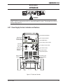
4.01 Power Supply Controls, Indicators and Features ............................................ 4-1
4.02 Weld Mode Selector ....................................................................................... 4-6
4.03 400 Amp Air-Cooled MIG Gun ........................................................................ 4-8
4.04 Installing A New Wire Conduit ........................................................................ 4-9
4.05 MIG Gun Maintenance .................................................................................. 4-10
4.06 Basic Welding Technique .............................................................................. 4-10
4.07 Stitch Welding Operation .............................................................................. 4-12
4.08 Spot Welding Operation ............................................................................... 4-12
4.09 Gas Selection for Gas Metal Arc Welding ..................................................... 4-13
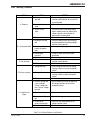
4.10 Welding Setting Selection Guide .................................................................. 4-14
SECTION 5:
MAINTENANCE & TROUBLESHOOTING .......................................................... 5-1
5.01 Routine Maintenance & Inspection................................................................. 5-1
5.02 Basic Troubleshooting .................................................................................... 5-3
5.03 Solving Problems Beyond the Welding Terminals .......................................... 5-3
5.04 Welding Problems .......................................................................................... 5-5
5.05 Power Supply Problems ................................................................................. 5-7
APPENDIX 1: FEEDROLL KITS ........................................................................... A-1
APPENDIX 2: POWER SUPPLY CIRCUIT DIAGRAM ................................................... A-2
LIMITED WARRANTY
WARRANTY SCHEDULE
GLOBAL CUSTOMER SERVICE CONTACT INFORMATION .......................... Inside Rear Cover
SAFETY INSTRUCTIONS
FABRICATOR 251
SECTION 1:
SAFETY INSTRUCTIONS AND WARNINGS
!
WARNING
PROTECT YOURSELF AND OTHERS FROM POSSIBLE SERIOUS INJURY OR DEATH. KEEP CHILDREN AWAY. PACEMAKER WEARERS KEEP
AWAY UNTIL CONSULTING YOUR DOCTOR. DO NOT LOSE THESE INSTRUCTIONS. READ OPERATING/INSTRUCTION MANUAL BEFORE
INSTALLING, OPERATING OR SERVICING THIS EQUIPMENT.
Welding products and welding processes can cause serious injury or death, or damage to other equipment or property, if the operator does not
strictly observe all safety rules and take precautionary actions.
Safe practices have developed from past experience in the use of welding and cutting. These practices must be learned through study and
training before using this equipment. Some of these practices apply to equipment connected to power lines; other practices apply to engine
driven equipment. Anyone not having extensive training in welding and cutting practices should not attempt to weld.
Safe practices are outlined in the American National Standard Z49.1 entitled: SAFETY IN WELDING AND CUTTING. This publication and other
guides to what you should learn before operating this equipment are listed at the end of these safety precautions. HAVE ALL INSTALLATION,
OPERATION, MAINTENANCE, AND REPAIR WORK PERFORMED ONLY BY QUALIFIED PEOPLE.
1.01
7. Use fully insulated electrode holders. Never dip holder in water to
cool it or lay it down on the ground or the work surface. Do not
touch holders connected to two welding machines at the same
time or touch other people with the holder or electrode.
Arc Welding Hazards
8. Do not use worn, damaged, undersized, or poorly spliced cables.
9. Do not wrap cables around your body.
WARNING
10. Ground the workpiece to a good electrical (earth) ground.
ELECTRIC SHOCK can kill.
11. Do not touch electrode while in contact with the work (ground)
circuit.
Touching live electrical parts can cause fatal shocks or
severe burns. The electrode and work circuit is electrically
live whenever the output is on. The input power circuit
and machine internal circuits are also live when power
is on. In semi-automatic or automatic wire welding, the
wire, wire reel, drive roll housing, and all metal parts
touching the welding wire are electrically live. Incorrectly
installed or improperly grounded equipment is a hazard.
12. Use only well-maintained equipment. Repair or replace damaged
parts at once.
13. In confined spaces or damp locations, do not use a welder with
AC output unless it is equipped with a voltage reducer. Use
equipment with DC output.
14. Wear a safety harness to prevent falling if working above floor
level.
15. Keep all panels and covers securely in place.
1. Do not touch live electrical parts.
2. Wear dry, hole-free insulating gloves and body protection.
3. Insulate yourself from work and ground using dry insulating mats
or covers.
WARNING
4. Disconnect input power or stop engine before installing or
servicing this equipment. Lock input power disconnect switch
open, or remove line fuses so power cannot be turned on
accidentally.
ARC RAYS can burn eyes and skin; NOISE can damage
hearing. Arc rays from the welding process produce
intense heat and strong ultraviolet rays that can burn
eyes and skin. Noise from some processes can damage
hearing.
5. Properly install and ground this equipment according to its Owner’s
Manual and national, state, and local codes.
6. Turn off all equipment when not in use. Disconnect power to
equipment if it will be left unattended or out of service.
1. Wear a welding helmet fitted with a proper shade of filter (see
ANSI Z49.1 listed in Safety Standards) to protect your face and
eyes when welding or watching.
2. Wear approved safety glasses. Side shields recommended.
August 22, 2008
1-1
Manual 0-5098
FABRICATOR 251
SAFETY INSTRUCTIONS
3. Use protective screens or barriers to protect others from flash
and glare; warn others not to watch the arc.
WARNING
4. Wear protective clothing made from durable, flame-resistant
material (wool and leather) and foot protection.
WELDING can cause fire or explosion.
5. Use approved ear plugs or ear muffs if noise level is high.
Sparks and spatter fly off from the welding arc. The flying
sparks and hot metal, weld spatter, hot workpiece, and
hot equipment can cause fires and burns. Accidental
contact of electrode or welding wire to metal objects
can cause sparks, overheating, or fire.
WARNING
FUMES AND GASES can be hazardous to your health.
1. Protect yourself and others from flying sparks and hot metal.
Welding produces fumes and gases. Breathing these
fumes and gases can be hazardous to your health.
2. Do not weld where flying sparks can strike flammable material.
1. Keep your head out of the fumes. Do not breath the fumes.
3. Remove all flammables within 35 ft (10.7 m) of the welding arc.
If this is not possible, tightly cover them with approved covers.
2. If inside, ventilate the area and/or use exhaust at the arc to remove
welding fumes and gases.
4. Be alert that welding sparks and hot materials from welding can
easily go through small cracks and openings to adjacent areas.
3. If ventilation is poor, use an approved air-supplied respirator.
5. Watch for fire, and keep a fire extinguisher nearby.
4. Read the Material Safety Data Sheets (MSDSs) and the
manufacturer’s instruction for metals, consumables, coatings, and
cleaners.
6. Be aware that welding on a ceiling, floor, bulkhead, or partition
can cause fire on the hidden side.
5. Work in a confined space only if it is well ventilated, or while
wearing an air-supplied respirator. Shielding gases used for
welding can displace air causing injury or death. Be sure the
breathing air is safe.
6. Do not weld in locations near degreasing, cleaning, or spraying
operations. The heat and rays of the arc can react with vapors to
form highly toxic and irritating gases.
7. Do not weld on closed containers such as tanks or drums.
8. Connect work cable to the work as close to the welding area as
practical to prevent welding current from traveling long, possibly
unknown paths and causing electric shock and fire hazards.
9. Do not use welder to thaw frozen pipes.
10. Remove stick electrode from holder or cut off welding wire at
contact tip when not in use.
7. Do not weld on coated metals, such as galvanized, lead, or
cadmium plated steel, unless the coating is removed from the
weld area, the area is well ventilated, and if necessary, while
wearing an air-supplied respirator. The coatings and any metals
containing these elements can give off toxic fumes if welded.
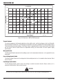
Eye protection filter shade selector for welding or cutting
(goggles or helmet), from AWS A6.2-73.
Welding or cutting
Torch soldering
Torch brazing
Oxygen Cutting
Light
Medium
Heavy
Gas welding
Light
Medium
Heavy
Shielded metal-arc
Manual 0-5098
Electrode Size
Filter
Welding or cutting
2
3 or 4
Under 1 in., 25 mm
1 to 6 in., 25-150 mm
Over 6 in., 150 mm
3 or 4
4 or 5
5 or 6
Under 1/8 in., 3 mm
1/8 to 1/2 in., 3-12 mm
Over 1/2 in., 12 mm
Under 5/32 in., 4 mm
5/32 to 1/4 in.,
Over 1/4 in., 6.4 mm
4 or 5
5 or 6
6 or 8
10
12
14
Electrode Size
Gas metal-arc
Non-ferrous base metal
All
Ferrous base metal
All
Gas tungsten arc welding
All
(TIG)
All
Atomic hydrogen welding
All
Carbon arc welding
All
Plasma arc welding
Carbon arc air gouging
Light
Heavy
Plasma arc cutting
Light Under 300 Amp
Medium 300 to 400 Amp
Heavy Over 400 Amp
1-2
Filter
11
12
12
12
12
12
12
14
9
12
14
August 22, 2008
SAFETY INSTRUCTIONS
FABRICATOR 251
2. If used in a closed area, vent engine exhaust outside and away
from any building air intakes.
WARNING
WARNING
FLYING SPARKS AND HOT METAL can cause injury.
Chipping and grinding cause flying metal. As welds cool,
they can throw off slag.
ENGINE FUEL can cause fire or explosion.
Engine fuel is highly flammable.
1. Wear approved face shield or safety goggles. Side shields
recommended.
1. Stop engine before checking or adding fuel.
2. Wear proper body protection to protect skin.
2. Do not add fuel while smoking or if unit is near any sparks or
open flames.
WARNING
3. Allow engine to cool before fueling. If possible, check and add
fuel to cold engine before beginning job.
CYLINDERS can explode if damaged.
4. Do not overfill tank — allow room for fuel to expand.
Shielding gas cylinders contain gas under high pressure.
If damaged, a cylinder can explode. Since gas cylinders
are normally part of the welding process, be sure to treat
them carefully.
5. Do not spill fuel. If fuel is spilled, clean up before starting engine.
WARNING
1. Protect compressed gas cylinders from excessive heat, mechanical
shocks, and arcs.
MOVING PARTS can cause injury.
2. Install and secure cylinders in an upright position by chaining
them to a stationary support or equipment cylinder rack to prevent
falling or tipping.
Moving parts, such as fans, rotors, and belts can cut fingers and hands
and catch loose clothing.
3. Keep cylinders away from any welding or other electrical circuits.
1. Keep all doors, panels, covers, and guards closed and
securely in place.
4. Never allow a welding electrode to touch any cylinder.
2. Stop engine before installing or connecting unit.
5. Use only correct shielding gas cylinders, regulators, hoses, and
fittings designed for the specific application; maintain them and
associated parts in good condition.
3. Have only qualified people remove guards or covers for
maintenance and troubleshooting as necessary.
6. Turn face away from valve outlet when opening cylinder valve.
4. To prevent accidental starting during servicing, disconnect
negative (-) battery cable from battery.
7. Keep protective cap in place over valve except when cylinder is in
use or connected for use.
5. Keep hands, hair, loose clothing, and tools away from moving
parts.
8. Read and follow instructions on compressed gas cylinders,
associated equipment, and CGA publication P-1 listed in Safety
Standards.
6. Reinstall panels or guards and close doors when servicing
is finished and before starting engine.
!
WARNING
WARNING
Engines can be dangerous.
SPARKS can cause BATTERY GASES TO EXPLODE;
BATTERY ACID can burn eyes and skin.
Batteries contain acid and generate explosive gases.
WARNING
1. Always wear a face shield when working on a battery.
2. Stop engine before disconnecting or connecting battery cables.
ENGINE EXHAUST GASES can kill.
3. Do not allow tools to cause sparks when working on a battery.
Engines produce harmful exhaust gases.
4. Do not use welder to charge batteries or jump start vehicles.
1. Use equipment outside in open, well-ventilated areas.
5. Observe correct polarity (+ and –) on batteries.
August 22, 2008
1-3
Manual 0-5098
FABRICATOR 251
SAFETY INSTRUCTIONS
1.02
WARNING
STEAM AND PRESSURIZED HOT COOLANT can burn
face, eyes, and skin.
The coolant in the radiator can be very hot and under
pressure.
1. Do not remove radiator cap when engine is hot. Allow engine to
cool.
2. Wear gloves and put a rag over cap area when removing cap.
3. Allow pressure to escape before completely removing cap.
LEAD WARNING
This product contains chemicals, including lead, or otherwise produces chemicals known to the State of California to cause cancer, birth defects and other reproductive harm. Wash hands after handling. (California
Health & Safety Code § 25249.5 et seq.)
Principal Safety Standards
Safety in Welding and Cutting, ANSI Standard Z49.1, from American
Welding Society, 550 N.W. LeJeune Rd., Miami, FL 33126.
Safety and Health Standards, OSHA 29 CFR 1910, from Superintendent
of Documents, U.S. Government Printing Office, Washington, D.C.
20402.
Recommended Safe Practices for the Preparation for Welding and
Cutting of Containers That Have Held Hazardous Substances, American
Welding Society Standard AWS F4.1, from American Welding Society,
550 N.W. LeJeune Rd., Miami, FL 33126.
National Electrical Code, NFPA Standard 70, from National Fire
Protection Association, Batterymarch Park, Quincy, MA 02269.
Safe Handling of Compressed Gases in Cylinders, CGA Pamphlet P1, from Compressed Gas Association, 1235 Jefferson Davis Highway,
Suite 501, Arlington, VA 22202.
Code for Safety in Welding and Cutting, CSA Standard W117.2, from
Canadian Standards Association, Standards Sales, 178 Rexdale
Boulevard, Rexdale, Ontario, Canada M9W 1R3.
Safe Practices for Occupation and Educational Eye and Face Protection,
ANSI Standard Z87.1, from American National Standards Institute,
1430 Broadway, New York, NY 10018.
Cutting and Welding Processes, NFPA Standard 51B, from National
Fire Protection Association, Batterymarch Park, Quincy, MA 02269.
NOTE
Considerations About Welding And The Effects of Low
Frequency Electric and Magnetic Fields
The following is a quotation from the General Conclusions Section of
the U.S. Congress, Office of Technology Assessment, Biological Effects
of Power Frequency Electric & Magnetic Fields - Background Paper,
OTA-BP-E-63 (Washington, DC: U.S. Government Printing Office, May
1989): “...there is now a very large volume of scientific findings based
on experiments at the cellular level and from studies with animals and
people which clearly establish that low frequency magnetic fields
interact with, and produce changes in, biological systems. While most
of this work is of very high quality, the results are complex. Current
scientific understanding does not yet allow us to interpret the evidence
in a single coherent framework. Even more frustrating, it does not yet
allow us to draw definite conclusions about questions of possible risk
or to offer clear science-based advice on strategies to minimize or
avoid potential risks.”
To reduce magnetic fields in the workplace, use the following
procedures.
1. Keep cables close together by twisting or taping them.
2. Arrange cables to one side and away from the operator.
3. Do not coil or drape cable around the body.
4. Keep welding power source and cables as far away from
body as practical.
ABOUT PACEMAKERS:
The above procedures are among those also normally
recommended for pacemaker wearers. Consult your
doctor for complete information.
Manual 0-5098
1-4
August 22, 2008
SAFETY INSTRUCTIONS
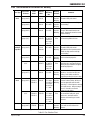
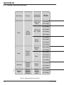
1.03
FABRICATOR 251
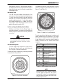
Symbol Chart
Note that only some of these symbols will appear on your model.
On
Single Phase
Wire Feed Function
Off
Three Phase
Wire Feed Towards
Workpiece With
Output Voltage Off.
Dangerous Voltage
Three Phase Static
Frequency ConverterTransformer-Rectifier
Welding Gun
Increase/Decrease
Remote
Purging Of Gas
Duty Cycle
Continuous Weld
Mode
Percentage
Spot Weld Mode
Circuit Breaker
AC Auxiliary Power
115V 15A
August 22, 2008
X
%
Fuse
Panel/Local
Amperage
Shielded Metal
Arc Welding (SMAW)
Voltage
Gas Metal Arc
Welding (GMAW)
Hertz (cycles/sec)
Gas Tungsten Arc
Welding (GTAW)
Frequency
Air Carbon Arc
Cutting (CAC-A)
Negative
Constant Current
Positive
Constant Voltage
Or Constant Potential
Direct Current (DC)
High Temperature
Protective Earth
(Ground)
Fault Indication
Line
Arc Force
Line Connection
Touch Start (GTAW)
Auxiliary Power
Variable Inductance
Receptacle RatingAuxiliary Power
V
t
Spot Time
Preflow Time
t1
t2
Postflow Time
2 Step Trigger
Operation
Press to initiate wirefeed and
welding, release to stop.
4 Step Trigger
Operation
Press and hold for preflow, release
to start arc. Press to stop arc, and
hold for preflow.
t
Burnback Time
IPM
Inches Per Minute
MPM
Meters Per Minute
Voltage Input
Art # A-04130
1-5
Manual 0-5098
FABRICATOR 251
1.04
SAFETY INSTRUCTIONS
Precautions De Securite En Soudage A L’arc
!
MISE EN GARDE
LE SOUDAGE A L’ARC EST DANGEREUX
PROTEGEZ-VOUS, AINSI QUE LES AUTRES, CONTRE LES BLESSURES GRAVES POSSIBLES OU LA MORT. NE LAISSEZ PAS LES ENFANTS
S’APPROCHER, NI LES PORTEURS DE STIMULATEUR CARDIAQUE (A MOINS QU’ILS N’AIENT CONSULTE UN MEDECIN). CONSERVEZ CES
INSTRUCTIONS. LISEZ LE MANUEL D’OPERATION OU LES INSTRUCTIONS AVANT D’INSTALLER, UTILISER OU ENTRETENIR CET EQUIPEMENT.
Les produits et procédés de soudage peuvent sauser des blessures graves ou la mort, de même que des dommages au reste du matériel et à la
propriété, si l’utilisateur n’adhère pas strictement à toutes les règles de sécurité et ne prend pas les précautions nécessaires.
En soudage et coupage, des pratiques sécuritaires se sont développées suite à l’expérience passée. Ces pratiques doivent être apprises par
étude ou entraînement avant d’utiliser l’equipement. Toute personne n’ayant pas suivi un entraînement intensif en soudage et coupage ne devrait
pas tenter de souder. Certaines pratiques concernent les équipements raccordés aux lignes d’alimentation alors que d’autres s’adressent aux
groupes électrogènes.
La norme Z49.1 de l’American National Standard, intitulée “SAFETY IN WELDING AND CUTTING” présente les pratiques sécuritaires à suivre.
Ce document ainsi que d’autres guides que vous devriez connaître avant d’utiliser cet équipement sont présentés à la fin de ces instructions de
sécurité.
SEULES DES PERSONNES QUALIFIEES DOIVENT FAIRE DES TRAVAUX D’INSTALLATION, DE REPARATION, D’ENTRETIEN ET D’ESSAI.
1.05
Dangers relatifs au soudage à l’arc
AVERTISSEMENT
L’ELECTROCUTION PEUT ETRE MORTELLE.
6. Arrêtez tout équipement après usage. Coupez l’alimentation de
l’équipement s’il est hors d’usage ou inutilisé.
7. N’utilisez que des porte-électrodes bien isolés. Ne jamais plonger
les porte-électrodes dans l’eau pour les refroidir. Ne jamais les
laisser traîner par terre ou sur les pièces à souder. Ne touchez
pas aux porte-électrodes raccordés à deux sources de courant en
même temps. Ne jamais toucher quelqu’un d’autre avec l’électrode
ou le porte-électrode.
8. N’utilisez pas de câbles électriques usés, endommagés, mal
épissés ou de section trop petite.
9. N’enroulez pas de câbles électriques autour de votre corps.
Une décharge électrique peut tuer ou brûler gravement.
L’électrode et le circuit de soudage sont sous tension
dès la mise en circuit. Le circuit d’alimentation et les
circuits internes de l’équipement sont aussi sous tension dès la mise en marche. En soudage automatique
ou semi-automatique avec fil, ce dernier, le rouleau ou
la bobine de fil, le logement des galets d’entrainement
et toutes les pièces métalliques en contact avec le fil de
soudage sont sous tension. Un équipement
inadéquatement installé ou inadéquatement mis à la terre
est dangereux.
10. N’utilisez qu’une bonne prise de masse pour la mise à la terre de
la pièce à souder.
11. Ne touchez pas à l’électrode lorsqu’en contact avec le circuit de
soudage (terre).
12. N’utilisez que des équipements en bon état. Réparez ou remplacez
aussitôt les pièces endommagées.
13. Dans des espaces confinés ou mouillés, n’utilisez pas de source
de courant alternatif, à moins qu’il soit muni d’un réducteur de
tension. Utilisez plutôt une source de courant continu.
14. Portez un harnais de sécurité si vous travaillez en hauteur.
1. Ne touchez pas à des pièces sous tension.
15. Fermez solidement tous les panneaux et les capots.
2. Portez des gants et des vêtements isolants, secs et non troués.
3
Isolez-vous de la pièce à souder et de la mise à la terre au moyen
de tapis isolants ou autres.
4. Déconnectez la prise d’alimentation de l’équipement ou arrêtez le
moteur avant de l’installer ou d’en faire l’entretien. Bloquez le
commutateur en circuit ouvert ou enlevez les fusibles de
l’alimentation afin d’éviter une mise en marche accidentelle.
5. Veuillez à installer cet équipement et à le mettre à la terre selon le
manuel d’utilisation et les codes nationaux, provinciaux et locaux
applicables.
Manual 0-5098
1-6
August 22, 2008
SAFETY INSTRUCTIONS
FABRICATOR 251
AVERTISSEMENT
AVERTISSEMENT
LE RAYONNEMENT DE L’ARC PEUT BRÛLER LES YEUX
ET LA PEAU; LE BRUIT PEUT ENDOMMAGER L’OUIE.
LES VAPEURS ET LES FUMEES SONT DANGEREUSES
POUR LA SANTE.
L’arc de soudage produit une chaleur et des rayons
ultraviolets intenses, susceptibles de brûler les yeux et
la peau. Le bruit causé par certains procédés peut
endommager l’ouïe.
Le soudage dégage des vapeurs et des fumées
dangereuses à respirer.
1. Eloignez la tête des fumées pour éviter de les respirer.
2. A l’intérieur, assurez-vous que l’aire de soudage est bien ventilée
ou que les fumées et les vapeurs sont aspirées à l’arc.
1. Portez une casque de soudeur avec filtre oculaire de nuance
appropriée (consultez la norme ANSI Z49 indiquée ci-après) pour
vous protéger le visage et les yeux lorsque vous soudez ou que
vous observez l’exécution d’une soudure.
3. Si la ventilation est inadequate, portez un respirateur à adduction
d’air approuvé.
2. Portez des lunettes de sécurité approuvées. Des écrans latéraux
sont recommandés.
4. Lisez les fiches signalétiques et les consignes du fabricant relatives aux métaux, aux produits consummables, aux revêtements
et aux produits nettoyants.
3. Entourez l’aire de soudage de rideaux ou de cloisons pour protéger
les autres des coups d’arc ou de l’éblouissement; avertissez les
observateurs de ne pas regarder l’arc.
5. Ne travaillez dans un espace confiné que s’il est bien ventilé; sinon,
portez un respirateur à adduction d’air. Les gaz protecteurs de
soudage peuvent déplacer l’oxygène de l’air et ainsi causer des
malaises ou la mort. Assurez-vous que l’air est propre à la respiration.
4. Portez des vêtements en matériaux ignifuges et durables (laine et
cuir) et des chaussures de sécurité.
5. Portez un casque antibruit ou des bouchons d’oreille approuvés
lorsque le niveau de bruit est élevé.
6. Ne soudez pas à proximité d’opérations de dégraissage, de
nettoyage ou de pulvérisation. La chaleur et les rayons de l’arc
peuvent réagir avec des vapeurs et former des gaz hautement
toxiques et irritants.
SELECTION DES NUANCES DE FILTRES OCULAIRS POUR LA PROTECTION
DES YEUX EN COUPAGE ET SOUDAGE (selon AWS á 8.2-73)
Dimension d'électrode ou
Epiasseur de métal ou
Intensité de courant
Nuance de
filtre oculaire
Brassage tendre
au chalumeau
toutes conditions
2
Brassage fort
au chalumeau
toutes conditions
3 ou 4
Opération de coupage
ou soudage
Soudage á l'arc sous gaz
avec fil plein (GMAW)
métaux non-ferreux
toutes conditions
11
métaux ferreux
toutes conditions
12
toutes conditions
12
toutes conditions
12
toutes conditions
12
toutes dimensions
12
Oxycoupage
mince
moins de 1 po. (25 mm)
moyen de 1 á 6 po. (25 á 150 mm)
épais
plus de 6 po. (150 mm)
2 ou 3
4 ou 5
5 ou 6
Soudage aux gaz
Dimension d'électrode ou
Nuance de
Epiasseur de métal ou
filtre oculaire
Intensité de courant
Opération de coupage
ou soudage
Soudage á l'arc sous gaz avec
électrode de tungstène (GTAW)
Soudage á l'hydrogène
atomique (AHW)
Soudage á l'arc avec
électrode de carbone (CAW)
Soudage á l'arc Plasma (PAW)
mince
moins de 1/8 po. (3 mm)
moyen de 1/8 á 1/2 po. (3 á 12 mm)
épais
Soudage á l'arc avec
électrode enrobees
(SMAW)
4 ou 5
Gougeage Air-Arc avec
électrode de carbone
5 ou 6
mince
12
plus de 1/2 po. (12 mm)
6 ou 8
épais
14
moins de 5/32 po. (4 mm)
10
5/32 á 1/4 po. (4 á 6.4 mm)
12
mince
moins de 300 amperès
9
plus de 1/4 po. (6.4 mm)
14
moyen
de 300 á 400 amperès
12
plus de 400 amperès
14
Coupage á l'arc Plasma (PAC)
épais
August 22, 2008
1-7
Manual 0-5098
FABRICATOR 251
SAFETY INSTRUCTIONS
7. Ne soudez des tôles galvanisées ou plaquées au plomb ou au
cadmium que si les zones à souder ont été grattées à fond, que si
l’espace est bien ventilé; si nécessaire portez un respirateur à adduction d’air. Car ces revêtements et tout métal qui contient ces
éléments peuvent dégager des fumées toxiques au moment du
soudage.
1. Portez un écran facial ou des lunettes protectrices
approuvées. Des écrans latéraux sont recommandés.
2. Portez des vêtements appropriés pour protéger la peau.
AVERTISSEMENT
AVERTISSEMENT
LES BOUTEILLES ENDOMMAGEES PEUVENT
EXPLOSER
LE SOUDAGE PEUT CAUSER UN INCENDIE OU UNE
EXPLOSION
L’arc produit des étincellies et des projections. Les
particules volantes, le métal chaud, les projections de
soudure et l’équipement surchauffé peuvent causer un
incendie et des brûlures. Le contact accidentel de
l’électrode ou du fil-électrode avec un objet métallique
peut provoquer des étincelles, un échauffement ou un
incendie.
1. Protégez-vous, ainsi que les autres, contre les étincelles et du
métal chaud.
Les bouteilles contiennent des gaz protecteurs sous
haute pression. Des bouteilles endommagées peuvent
exploser. Comme les bouteilles font normalement partie
du procédé de soudage, traitez-les avec soin.
1. Protégez les bouteilles de gaz comprimé contre les sources de
chaleur intense, les chocs et les arcs de soudage.
2. Enchainez verticalement les bouteilles à un support ou à un cadre
fixe pour les empêcher de tomber ou d’être renversées.
3. Eloignez les bouteilles de tout circuit électrique ou de tout soudage.
2. Ne soudez pas dans un endroit où des particules volantes ou des
projections peuvent atteindre des matériaux inflammables.
4. Empêchez tout contact entre une bouteille et une électrode de
soudage.
3. Enlevez toutes matières inflammables dans un rayon de 10, 7
mètres autour de l’arc, ou couvrez-les soigneusement avec des
bâches approuvées.
5. N’utilisez que des bouteilles de gaz protecteur, des détendeurs,
des boyauxs et des raccords conçus pour chaque application
spécifique; ces équipements et les pièces connexes doivent être
maintenus en bon état.
4. Méfiez-vous des projections brulantes de soudage susceptibles
de pénétrer dans des aires adjacentes par de petites ouvertures
ou fissures.
6. Ne placez pas le visage face à l’ouverture du robinet de la bouteille
lors de son ouverture.
5. Méfiez-vous des incendies et gardez un extincteur à portée de la
main.
7. Laissez en place le chapeau de bouteille sauf si en utilisation ou
lorsque raccordé pour utilisation.
6. N’oubliez pas qu’une soudure réalisée sur un plafond, un plancher,
une cloison ou une paroi peut enflammer l’autre côté.
8. Lisez et respectez les consignes relatives aux bouteilles de gaz
comprimé et aux équipements connexes, ainsi que la publication
P-1 de la CGA, identifiée dans la liste de documents ci-dessous.
7. Ne soudez pas un récipient fermé, tel un réservoir ou un baril.
8. Connectez le câble de soudage le plus près possible de la zone
de soudage pour empêcher le courant de suivre un long parcours
inconnu, et prévenir ainsi les risques d’électrocution et d’incendie.
AVERTISSEMENT
9. Ne dégelez pas les tuyaux avec un source de courant.
LES MOTEURS PEUVENT ETRE DANGEREUX
10. Otez l’électrode du porte-électrode ou coupez le fil au tube-contact lorsqu’inutilisé après le soudage.
11. Portez des vêtements protecteurs non huileux, tels des gants en
cuir, une chemise épaisse, un pantalon revers, des bottines de
sécurité et un casque.
AVERTISSEMENT
LES ETINCELLES ET LES PROJECTIONS BRULANTES
PEUVENT CAUSER DES BLESSURES.
LES GAZ D’ECHAPPEMENT DES MOTEURS PEUVENT
ETRE MORTELS.
Les moteurs produisent des gaz d’échappement nocifs.
1. Utilisez l’équipement à l’extérieur dans des aires ouvertes et bien
ventilées.
2. Si vous utilisez ces équipements dans un endroit confiné, les
fumées d’échappement doivent être envoyées à l’extérieur, loin
des prises d’air du bâtiment.
Le piquage et le meulage produisent des particules
métalliques volantes. En refroidissant, la soudure peut
projeter du éclats de laitier.
Manual 0-5098
1-8
August 22, 2008
SAFETY INSTRUCTIONS
FABRICATOR 251
4. N’utilisez pas une source de courant de soudage pour charger un
accumulateur ou survolter momentanément un véhicule.
AVERTISSEMENT
5. Utilisez la polarité correcte (+ et –) de l’accumulateur.
LE CARBURANT PEUR CAUSER UN INCENDIE OU UNE
EXPLOSION. Le carburant est hautement inflammable.
AVERTISSEMENT
1. Arrêtez
le moteur avant de vérifier le niveau e
carburant ou de faire le plein.
LA VAPEUR ET LE LIQUIDE DE REFROIDISSEMENT
BRULANT SOUS PRESSION PEUVENT BRULER LA
PEAU ET LES YEUX.
2. Ne faites pas le plein en fumant ou proche d’une source d’étincelles
ou d’une flamme nue.
3. Si c’est possible, laissez le moteur refroidir avant de faire le plein
de carburant ou d’en vérifier le niveau au début du soudage.
Le liquide de refroidissement d’un radiateur peut être
brûlant et sous pression.
4. Ne faites pas le plein de carburant à ras bord: prévoyez de l’espace
pour son expansion.
1. N’ôtez pas le bouchon de radiateur tant que le moteur n’est pas
refroidi.
5. Faites attention de ne pas renverser de carburant. Nettoyez tout
carburant renversé avant de faire démarrer le moteur.
2. Mettez des gants et posez un torchon sur le bouchon pour l’ôter.
3. Laissez la pression s’échapper avant d’ôter complètement le
bouchon.
AVERTISSEMENT
DES PIECES EN MOUVEMENT PEUVENT CAUSER DES
BLESSURES.
PLOMB AVERTISSEMENT
Des pièces en mouvement, tels des ventilateurs, des
rotors et des courroies peuvent couper doigts et mains,
ou accrocher des vêtements amples.
Ce produit contient des produits chimiques, comme le
plomb, ou engendre des produits chimiques, reconnus
par l’état de Californie comme pouvant être à l’origine
de cancer, de malformations fœtales ou d’autres
problèmes de reproduction. Il faut se laver les mains
après toute manipulation. (Code de Californie de la
sécurité et santé, paragraphe 25249.5 et suivants)
1. Assurez-vous que les portes, les panneaux, les capots et les
protecteurs soient bien fermés.
2. Avant d’installer ou de connecter un système, arrêtez le moteur.
3. Seules des personnes qualifiées doivent démonter des protecteurs
ou des capots pour faire l’entretien ou le dépannage nécessaire.
1.06
4. Pour empêcher un démarrage accidentel pendant l’entretien,
débranchez le câble d’accumulateur à la borne négative.
Safety in Welding and Cutting, norme ANSI Z49.1, American Welding
Society, 550 N.W. LeJeune Rd., Miami, FL 33128.
5. N’approchez pas les mains ou les cheveux de pièces en
mouvement; elles peuvent aussi accrocher des vêtements amples
et des outils.
Safety and Health Standards, OSHA 29 CFR 1910, Superintendent of
Documents, U.S. Government Printing Office, Washington, D.C. 20402.
Recommended Safe Practices for the Preparation for Welding and
Cutting of Containers That Have Held Hazardous Substances, norme
AWS F4.1, American Welding Society, 550 N.W. LeJeune Rd., Miami,
FL 33128.
6. Réinstallez les capots ou les protecteurs et fermez les portes après
des travaux d’entretien et avant de faire démarrer le moteur.
National Electrical Code, norme 70 NFPA, National Fire Protection
Association, Batterymarch Park, Quincy, MA 02269.
AVERTISSEMENT
Safe Handling of Compressed Gases in Cylinders, document P-1, Compressed Gas Association, 1235 Jefferson Davis Highway, Suite 501,
Arlington, VA 22202.
DES ETINCELLES PEUVENT FAIRE EXPLOSER UN
ACCUMULATEUR; L’ELECTROLYTE D’UN ACCUMULATEUR PEUT BRULER LA PEAU ET LES YEUX.
Code for Safety in Welding and Cutting, norme CSA W117.2 Association canadienne de normalisation, Standards Sales, 276 Rexdale Boulevard, Rexdale, Ontario, Canada M9W 1R3.
Les accumulateurs contiennent de l’électrolyte acide et
dégagent des vapeurs explosives.
Safe Practices for Occupation and Educational Eye and Face Protection, norme ANSI Z87.1, American National Standards Institute, 1430
Broadway, New York, NY 10018.
1. Portez toujours un écran facial en travaillant sur un accumu-lateur.
2. Arrêtez le moteur avant de connecter ou de déconnecter des câbles
d’accumulateur.
Cutting and Welding Processes, norme 51B NFPA, National Fire Protection Association, Batterymarch Park, Quincy, MA 02269.
3. N’utilisez que des outils anti-étincelles pour travailler sur un
accumulateur.
August 22, 2008
Principales Normes De Securite
1-9
Manual 0-5098
FABRICATOR 251
1.07
SAFETY INSTRUCTIONS
Graphique de Symbole
Seulement certains de ces symboles apparaîtront sur votre modèle.
Sous Tension
Mono Phasé
Déroulement du Fil
Hors Tension
Trois Phasé
Alimentation du Fil Vers
la Pièce de Fabrication
Hors Tension
Tri-Phase Statique
Tension dangereuse
Fréquence Convertisseur
Transformateur-Redresseur
Torch de Soudage
Augmentez/Diminuer
Distant
Purge Du Gaz
Facteur de Marche
Mode Continu de
Soudure
Pourcentage
Soudure Par Point
Disjoncteur
Source AC Auxiliaire
X
%
Fusible
Panneau/Local
Intensité de Courant
Soudage Arc Electrique
Avec Electrode Enrobé
(SMAW)
Tension
Soudage á L’arc Avec
Fil Electrodes Fusible
(GMAW)
Hertz (cycles/sec)
Soudage á L’arc Avec
Electrode Non Fusible
(GTAW)
Fréquence
Decoupe Arc Carbone
(CAC-A)
t
Duréc du Pulse
Durée de Pré-Dèbit
t1
t2
Durée de Post-Dèbit
Détente à 2-Temps
Appuyez pour dèruarer
l’alimentation du fils et la soudure,
le relâcher pour arrêter.
Détente à 4-Temps
Courant Constant
Négatif
Positif
Tension Constante
Ou Potentiel Constant
Courant Continue (DC)
Haute Température
Terre de Protection
Amorçage de L’arc au
Contact (GTAW)
Connexion de la Ligne
115V 15A
Manual 0-5098
t
Probléme de Terre
IPM
Pouces Par Minute
MPM
Mètres Par Minute
Force d'Arc
Ligne
Source Auxiliaire
Maintenez appuyez pour pré-dèbit,
relailez pour initier l'arc. Appuyez
pour arrêter l'arc, et mainteuir pour
pré-dèbit.
Inductance Variable
V
Tension
Classement de PriseSource Auxiliaire
Art # A-07639
1-10
August 22, 2008
FABRICATOR 251
SECTION 2:
INTRODUCTION
2.01 How To Use This Manual
This Operating Manual applies to only the specification
or part numbers listed on page i.
To ensure safe operation, read the entire manual, including
the chapter on safety instructions and warnings.
Throughout this manual, the words WARNING,
CAUTION, and NOTE may appear. Pay particular attention
to the information provided under these headings. These
special annotations are easily recognized as
follows:
!
WARNING
A WARNING gives information regarding
possible personal injury.
2.02 Equipment Identification
The unit’s identification number (specification or part
number), model, and serial number usually appear on a
nameplate attached to the rear panel. In some cases, the
nameplate may be attached to the control panel.
Equipment which does not have a name plate such as
gun and cable assemblies is identified only by the
specification or part number printed on the shipping
container. Record these numbers on the bottom of page
i for future reference.
2.03 Receipt Of Equipment
When you receive the equipment, check it against the
invoice to make sure it is complete and inspect the
equipment for possible damage due to shipping. If there
is any damage, notify the carrier immediately to file a
claim. Furnish complete information concerning damage
claims or shipping errors to the location in your area
listed in the inside back cover of this manual.
Include all equipment identification numbers as described
above along with a full description of the parts in error.
CAUTION
A CAUTION refers to possible equipment
damage.
NOTE
A NOTE offers helpful information concerning
certain operating procedures.
Additional copies of this manual may be purchased by
contacting Valley National Gases at the address and phone
number listed in the inside back cover of this manual.
Include the Operating Manual number and equipment
identification numbers.
August 22, 2008
2-1
FABRICATOR 251
2.04 General Information
2.06 Protective Filter Lenses
The Fabricator 251 is a semiautomatic Gas Metal Arc
Welder (GMAW-commonly MIG) with an integrated wire
feed unit. This Power Supply is designed to meet the broad
operating needs of the metal fabrication industry where
production efficiency is vital. The Fabricator 251 is
designed and manufactured to meet the requirements of
CSA and IEC 60974-1 standards.
Protective filter lenses are provided to reduce the intensity
of radiation entering the eye thus filtering out harmful
infrared, ultraviolet radiation and a percentage of the
visible light. Such filter lenses are incorporated within face
shields. To prevent damage to the filter lenses from molten
or hard particles an additional hard clear glass or special
plastic external cover lens should be used. This cover
lens should always be kept in place and replaced before
the damage impairs your vision while welding.
The Fabricator 251 gives excellent performance on mild
steel, stainless steel, aluminum, silicon bronze and some
hard facing wires with Argon based shielding gases. The
Power Supply also gives excellent results on mild steel
using Carbon Dioxide shielding gas.
The Fabricator 251 is supplied as a complete package
ready to weld (apart from gas cylinder and electrode wire).
The following instructions detail how to correctly set up
the welder and give guidelines on gaining the best
production efficiency from the Power Supply. Please read
these instructions thoroughly before using your Fabricator
welder.
2.05 Safety
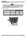
Approximate range of
welding current
Up to 150
150-250
250-300
300-350
Over 350
Filter lens
required for
MIG
Shade 10
Shade 11
Shade 12
Shade 13
Shade 14
Table 2-1: Filter Lens Size Versus Welding Current
• Ensure the machine is correctly installed, if necessary, by a qualified electrician.
It is recommended to use a welding helmet, conforming
to the local relevant Standards when electric arc welding.
Use a welding helmet in serviceable condition with the
correct filter lens. Refer to Table 2-1 above and AWS table
in Section 1.
• Ensure the Power Supply is grounded correctly
(electrically) in accordance with local regulations.
2.07 User Responsibility
The following basic safety rules should always be followed:
• Excessive heat in the welding cables may cause fire.
Never weld with poor electrical connections, damaged welding cables or exceed the welding cable
current rating as this will produce excessive heat
and may cause a fire.
• Always wear the correct protective clothing for protection from sparks, molten particles and arc rays.
• When welding in confined spaces, always ensure
adequate ventilation and constant observation of the
operator.
• Keep combustible materials away from the welding
area. Have a suitable fire extinguisher handy.
• Never watch the welding arc with naked eyes. Always use and wear a welding mask fitted with the
correct filter lens.
• Do not stand on damp ground when welding.
For more complete safety advice please read section 1.
2-2
This equipment will perform as per the information
contained herein when installed, operated, maintained and
repaired in accordance with the instructions provided. This
equipment must be checked periodically. Defective
equipment (including welding leads) should not be used.
Parts that are broken, missing, plainly worn, distorted or
contaminated, should be replaced immediately. Should
such repairs or replacements become necessary, it is
recommended that such repairs be carried out by
appropriately qualified persons approved by Valley
National Gases. Advice in this regard can be obtained by
contacting Valley National Gases.
This equipment or any of its parts should not be altered
from standard specification without prior written approval
of Valley National Gases. The purchaser of this equipment
shall have the sole responsibility for any malfunction which
results from improper use or unauthorized modification
from standard specification, faulty maintenance, damage
or improper repair by anyone other than appropriately
qualified persons approved by Valley National Gases.
August 22, 2008
FABRICATOR 251
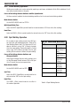
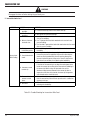
2.08 Duty Cycle
The rated duty cycle of a welding Power Supply is the operating time it may be used at its rated output current without
exceeding the temperature limits of the insulation of the component parts. To explain the ten minute duty cycle period
the following example is used. Suppose a welding Power Supply is designed to operate at 60% duty cycle, 250
amperes at 26.5 volts. This means that it has been designed and built to provide the rated amperage (250A) at the
rated load voltage (26.5V), for 6.0 minutes out of every 10 minute period (60% of 10 minutes is 6.0 minutes). During
the other 4.0 minutes of the 10 minute period the Power Supply must idle and be allowed to cool. The thermal cutout
will operate if the duty cycle is exceeded.
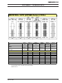
2.09 Specifications
MIG Gun Specifications
Gun Catalog Number
43340VNG
Gun Type
Valley National Gases 400 Amp
Gun Cable Length
15 ft (4.5m)
Table 2-2: MIG Gun Specifications
Control Circuit Supply
Wire Drive Motor Supply
Wire Speed Range
Wire Diameter
Mild Steel:
Stainless Steel:
Aluminum:
Flux Cored:
Wire Spool Size Capacity
Wire Drive Specifications
30VA @ 24VAC
180VA @ 14 to 46VDC
80 to 800 ipm
(2 to 20 m/min)
.023"
.030"
.035"
.045"
(0.6mm)
(0.8mm)
(0.9mm)
(1.2mm)
Y
Y
Y
Y
Y
Y
Y
Y
Y
Y
Y
Y
Y
Y
44 lb, 33 lb, 10 lb, 8" and 12" wire spool sizes.
Table 2-3: Wire Drive Specifications
August 22, 2008
2-3
FABRICATOR 251
Fabricator 251
100048DVN
Package System Part Number
871987
Power Source Part Number
227lb (103kg)
Power Source Weight
Power Source Dimensions HxWxD
(including wheels and cylinder carrier)
Nominal Input Voltage
32” x 27-3/16” x 36-3/4”
(813 x 691 x 933mm)
208V
230V
1Ø
Number of Phases
60 Hz
Frequency
10ft (3m) 10AWG
NEMA 6-50P
Flexible Supply Cable Size
Supply Plug
Rated Input Current @ 100% Duty Cycle
* 36A
* 32.6A
7.5 kVA
7.5 kVA
68A
62A
Generator Requirements
20 kVA
20 kVA
Supply VA @ Maximum Output
Rated kVA @ 100% Duty Cycle
Maximum Input Current @ 250A Output
15 kVA
15 kVA
Recommended Primary Circuit Size
50A
50A
Recommended Minimum Primary Fuse Size
50A
50A
Open Circuit Voltage Range
15.6 – 45.9V DC
15.6 – 45.9V DC
Welding Arc Voltage Range
14.5 – 31.7V DC
14.5 – 31.7V DC
20 – 300A DC
20 – 300A DC
Rated Output Duty Cycle
250A/26.5V @ 60%
250A/26.5V @ 60%
Maximum Duty Cycle
300A/31.7V @ 40%
300A/31.7V @ 40%
195A DC at 24V
195A DC at 24V
Output Current Range
100% Duty Cycle Output Rating
10 minutes
Duty Cycle Period
24
Number of Output Voltage Values
Electrode Wire Type and Diameter
Mild / Stainless Steel
.023” (0.6mm) – .045” (1.2mm)
Aluminum
.030” (0.8mm) – 1/16” (1.6mm)
Flux Cored
.030” (0.8mm) – 1/16” (1.6mm)
Wire Feed Speed Range
80 – 800 ipm (2 – 20 m/min )
Wire Spool Size Diameter
8” / 12” (200mm / 300mm)
0 – 0.6 seconds
Burn-Back Timer Range
0.16 seconds
Burn-Back Time Factory Set to
Spot Timer Range
0.5 – 9 seconds
Dwell Timer Range
1 – 12 seconds
Stitch Weld Time Weld (Stitch) Time
0.5 – 9 seconds
Dwell (non-weld) Time
1 – 12 seconds
Thermal Protection
Operating Temperature Range
Self-resetting thermostat fitted to rectifier and
transformer
32° to 104°F (0° to 40°C)
* The Rated Input Current should be used for the determination of cable size & supply
requirements.
Table 2-4: Machine Specifications
2-4
August 22, 2008
FABRICATOR 251
2.10 Included Items
Fabricator 251 Package SystemContents
Factory Fitted Wheeling Kit
Factory Fitted Dual Cylinder Rack
Factory Fitted Primary Power Cable 8AWG, 10ft (3m) with Plug NEMA 6-50P
Work Lead 10ft (3m)
Cable Stowage Hooks
Regulator/Flow Meter – Argon Mix Gases
Valley National Gases air cooled MIG Gun, 400 Amp, 15ft (4.5m)
Fitted Feed Roll for .035” - .045” (0.9 – 1.2mm) solid wire
Table 2-5: System Contents
2.11 Optional Accessories
Refer to the Appendix section of this manual for the list of available options and accessories.
August 22, 2008
2-5
FABRICATOR 251
NOTES:
2-6
August 22, 2008
FABRICATOR 251
SECTION 3:
INSTALLATION
3.01 Environment
3.02 Location
Be sure to locate the Power Supply according to the
following guidelines:
In areas, free from moisture and dust.
In areas, free from oil, steam and corrosive gases.
The Fabricator 251 is NOT designed for use in
environments with increased hazard of electric shock.
Examples of environments with increased hazard of
electric shock are:
In locations in which freedom of movement is restricted,
so that the operator is forced to perform the work in a
cramped (kneeling, sitting or lying) position with physical
contact with conductive parts;
In locations which are fully or partially limited by
conductive elements, and in which there is a high risk of
unavoidable or accidental contact by the operator, or
In areas, not subjected to abnormal vibration or shock.
In areas, not exposed to direct sunlight or rain.
Place at a distance of 1 ft (300 mm) or more from walls
or similar that could restrict natural air flow for cooling.
The minimum ground clearance for these products is 5.5"
(140mm).
3.03 Ventilation
Since the inhalation of welding fumes can be harmful,
ensure that the welding area is effectively ventilated.
In wet or damp hot locations where humidity or
perspiration considerably reduces the skin resistance of
the human body and the insulation properties of
accessories.
Environments with increased hazard of electric shock do
not include places where electrically conductive parts in
the near vicinity of the operator, which can cause increased
hazard, have been insulated.
August 22, 2008
3-1
FABRICATOR 251
3.04 Mains Supply Voltage Requirements
The Mains supply voltage should be within ± 10% of the rated Mains supply voltage. Too low of a supply voltage may
cause poor welding performance or wirefeeder malfunction. Too high of a supply voltage will cause components to
overheat and possibly fail.
Install a power outlet for each Power Supply and fit fuses as per the machine specifications.
!
WARNING
Valley National Gases advises that your Fabricator 251 be electrically connected by a qualified electrical
trades-person.
The Fabricator 251 Power Supply is factory connected for the following input power supply voltage:
Input Power
Lead Current Lead
Machine
Supply Lead Size
Rating
Length Voltage Setting Duty Cycle
8 AWG
40 Amps 10ft (3m)
230V
250A @ 60%
Table 3-1: Factory Fitted Input Power Supply Leads Fitted to the Fabricator 251
3.05 Alternative Mains Supply Voltages
!
WARNING
The Fabricator 251 input power supply lead should be replaced with leads as specified in Table 3-2 when
the Fabricators input power supply voltage is changed.
The Power Supply is suitable for use on the following input power supply voltages:
Input Power Supply
Voltage Setting
208V
230V
Mains Supply Input Power
Lead Size
Outlet Size Fuse Size Duty Cycle
8AWG (8.0mm2) 50 Amps
50 Amps 250A @ 60%
8AWG (8.0mm2) 50 Amps
50 Amps 250A @ 60%
Table 3-2: Mains Supply Lead Sizes for Alternative Mains Supply Voltages
National Electrical Code Standards permit the rating of the fuse or thermal circuit breaker protecting the circuit conductors
to be double the standard rating for any circuit used exclusively for an electric arc welder. Check local requirements for
your situation in this regard.
3-2
August 22, 2008
FABRICATOR 251
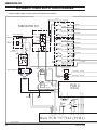
Changing the Voltage Selection
1. Disconnect the power supply from the input power source.
2. Refer to Figure 3-1. The power supply comes wired for 230V. Locate the two blue input power wires where they
are secured to the input voltage selection block. Loosen the set screw for both voltage locations.
3. Remove the blue wires from the current location and insert them into the new voltage location. Secure by tightening the set screw onto the uninsulated portion of the wires. Secure the other voltage set screw as well.
208V connection
230V connection
Art # A-07332
Figure 3-1: Voltage Selections for Fabricator 251 (Wired for 230V)
August 22, 2008
3-3
FABRICATOR 251
7. Fit the electrode wire spool to the wire reel hub
located behind the electrode wire compartment
door.
3.06 Quick Setup
CAUTION
To obtain adequate air flow and cooling for
the Power Supply components, the four
wheels must be fitted. Alternatively, the Power
Supply may be raised 5.5" (140 mm)from the
floor using supports that do not restrict
airflow.
8. Fit the Valley National Gases MIG gun and trigger
wires through/to the front of the unit.
9. Remove the contact tip from the gun.
10. With the gun lead reasonably straight, feed the
wire through the wire drive rolls and gun.
11. Fit the appropriate contact tip and replace insulator
and nozzle.
NOTE
The steps in this subsection are intended for
individuals experienced in the set up of this
type welder. More detailed setup instructions
are in the 3.07 and following subsections.
1. Connect the work lead to the negative (-) socket
(positive + for Self Shielded Flux Cored Wire)
2. Connect the GUN lead to the positive (+) socket
(negative - for Self Shielded Flux Cored Wire)
NOTE
See section 3.15 "Polarity Changeover" for
more detail and exceptions!
3. Position a gas cylinder on the rear tray and secure
to the Power Supply cylinder bracket with the
chain provided. If this arrangement is not used
then ensure that the gas cylinder is secured to a
building pillar, wall bracket or otherwise securely
fixed in an upright position.
!
WARNING
If the gas cylinder is not secured to the
cylinder tray, the power supply must be kept
from moving to avoid over-extending the gas
hose which can result in personal injury,
damage to the power supply, flow meter and
gas cylinder.
4. Fix the cable stowage hook to the Power Supply
cylinder bracket with the bolts provided.
5. Fit the gas Regulator/Flow Meter to the gas
cylinder and connect the gas hose from the rear
of the Power Supply to the Flow Meter outlet.
6. The machine is fitted with a .035/.045” vee groove
feed roll suited for hard wire. Change this feed
roll if required to fit your chosen wire size.
3-4
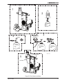
3.07 Installation of Shielding Gas
(GMAW) Process
NOTE
Shielding Gas is not required if the unit is used
with self shielded FCAW (flux cored arc
welding) wires
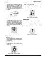
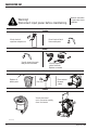
1. Cylinder positioning: Block the wheels of the unit so
it cannot roll. Carefully stand the cylinder on the tray
and with one foot, press against the bottom of the
cylinder to assure it is against the back of the unit.
Chain the cylinder in place. (Refer to Figure 3-2 for
Wheel Kit cylinder installation)
2. Cracking: Remove the large metal cap on top of the
cylinder by rotating counter clockwise. Next remove
the dust seal. Position yourself so the valve is pointed
away from you and quickly open and close the valve
for a burst of gas. This is called “Cracking” and is
done to blow out any foreign matter that may be
lodged in the fitting. (Figure 3-2.)
3. Fit Regulator/Flow Meter to cylinders: Screw the
regulator into the appropriate cylinder. (Figure 3-2)
The nuts on the regulator and hose connections are
right hand (RH) threaded and need to be turned in a
clockwise direction in order to tighten. Tighten with a
wrench.
CAUTION
Match regulator to cylinder. NEVER CONNECT
a regulator designed for a particular gas or
gases to a cylinder containing any other gas.
4. Attach supplied gas line between the regulator output
and the desired input at the rear of the power supply
depending on Spool Gun or MIG Gun use. (Refer to
Figure 3-2 and 3-12).
August 22, 2008
FABRICATOR 251
1
Cap
2
Shielding
Gas
“Cracking”
/8”
3
4
Regulator and
Flow Meter
11
Shielding
Gas
Shielding
Gas
Shielding
Gas
Stowage Hook
Art # A-07278
5
Gas Hose
Figure 3-2 Gas Cylinder Installation
August 22, 2008
3-5
FABRICATOR 251
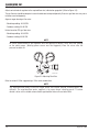
Adjusting Regulator
Adjust control knob of regulator to the required flow rate, indicated on gauge dial. (Refer to Figure 3-3)
The gas flow rate should be adequate to cover the weld zone to stop weld porosity. Excessive gas flow rates may cause
turbulence and weld porosity.
Argon or argon based gas flow rates:
- Workshop welding: 20-30 CFH
- Outdoors welding: 30-40 CFH
Helium based or CO2 gas flow rates:
- Workshop welding: 30-40 CFH
- Outdoors welding: 40-50 CFH
NOTE
All valves downstream of the regulator must be opened to obtain a true flow rate reading
on the outlet gauge. (Welding power source must be triggered) Close the valves after the
pressure has been set.
Art # A-07280
Figure 3-3: Adjusting Flow Rate
Refer to section 4.09 for suggested gas / filler metal combinations.
NOTE
The regulator/flow meters used with argon based and carbon dioxide shielding gases are
different. The regulator/flow meter supplied is for argon based shielding gases. If carbon
dioxide is to be used a suitable carbon dioxide regulator/flow meter will need to be fitted.
3-6
August 22, 2008
FABRICATOR 251
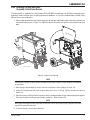
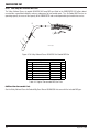
3.08 Attaching the Gun and Cable
Assembly to the Power Source
The Fabricator 251 is supplied with a Valley National Gases 400 AMP air-cooled gun. This MIG gun is designed with an
ergonomic handle and fewer parts to reduce performance problems. It also uses standard readily available Valley
National Gases consumable parts.
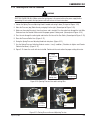
1. Open the door panel to the machine by inserting your left and right index fingers into the two release mechanisms
marked with hand arrows in Figure 3-4. Slide them toward each other and pull the cover outward and up to
open.
Set
up C
h ar t
Art # A-07142_AB
Figure 3-4: Door Panel Opening
NOTE
Lubricate the O-ring on the quick-connect fitting of the gun cable with grease (Dow company #4 compound
or equivalent).
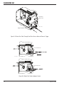
2. Route the gun cable through the access hole in the front panel. Refer to Figures 3-5 and -3-6.
3. Loosen the thumbscrew and insert the gun cable end as far as it will go. Tighten thumbscrew. Refer to
Figure 3-6.
4. Align the keyways of the Gun Switch connector with the receptacle below the gun cable and plug them together.
Secure by turning the locking ring to the right (clockwise ). Refer to Figure 3-6.
NOTE
When disconnecting gun switch leads from the machine, loosen the locking ring and grab the connectors
and pull. Do not pull on the wires.
5. To remove the gun, reverse these directions.
August 22, 2008
3-7
FABRICATOR 251
Front Panel
Access Hole
Art # 0-7148
Trigger Receptacle
Figure 3-5: Route Gun Cable Through Front Panel Access Hole and Connect Trigger
Loosen Thumbscrew
Art # A-07149
Tighten Thumbscrew
Figure 3-6: Mount Gun Cable to Adapter Socket
3-8
August 22, 2008
FABRICATOR 251
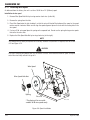
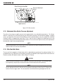
3.09 Input And Output Wire Guide
Installation
To ensure proper wire feed, the groove closest to the
motor must match the electrode wire size being used.
Refer to Figure 3-7.
.045” (1.2mm) Stamping
Install the input wire guide (the longer one) by loosening
the input guide lockscrew and inserting the guide into
the hole in the feedhead assembly. The recessed end of
the guide should be toward the wire spool. Adjust the
guide so that it is clear of the feed rolls and tighten the
input guide lockscrew.
Install the output wire guide in the same manner, with
the conical end toward the feed rolls. The tip of the conical end should be as close to the feed rolls as practical.
Tighten the output guide lockscrew.
.045
1.2
.045” (1.2mm) Groove
Art: A-07150
NOTE
Before tightening the input and output guide
lockscrews, install the drive roll to help in the
alignment of the wire guides.
Input Guide Lockscrew
Output Guide Lockscrew
The size that is visible when
fitting the feedroll is the groove
size in use.
Figure 3-8: Feedroll Example
NOTE
All grooved feed rolls have their wire size or
range stamped on the side of the roll. On rolls
with different size grooves, the outer (visible
when installed) stamped wire size indicates
the groove in use.
Refer to feed roll kit #375980 in the Appendix for the
proper selection and ordering of feed roll kits. Kit includes
drive rolls, an input wire guide and an output wire guide
for a specific wire type and size.
Art # A-07445
Feed rolls are removed by twisting the feed roll retainer
cap and aligning the retaining knob splines/tabs with the
drive gear splines. Feedrolls are installed by putting the
feedroll onto the drive gear splines and twisting the
feedroll retainer cap so that the splines/tabs rest against
the face of the feedroll where they will click into place.
Input Wire Guide
Output Wire Guide
Figure 3-7: Wire Guide Installation
3.10 Selection and Installation of
Feedrolls
A Feedroll consists of two different sized grooves. As
delivered from the factory the drive roll is installed for
.035” / .045” .
The stamped marking on the feedroll refers to the groove
furthest from the stamped marking. When mounted, that
will be the groove closest to the motor and the one to
thread.
August 22, 2008
NOTE
Installation of all styles of feed rolls for the
Fabricator 251 are identical.
WARNING
The welding wire is electrically Hot if it is fed
by depressing gun switch. Electrode contact
to work piece will cause an arc with gun switch
depressed.
3-9
FABRICATOR 251
3.11 Installing Wire Spool
As delivered from the factory, the unit is set for a 33/44 lb. or 12" (300mm) spool.
Installation of wire spool
1. Remove Wire Spool Hub Nut by turning counter clock wise (to the left).
2. Remove the spring from the hub.
3. Place Wire Spool onto the hub, loading it so that the wire will feed off the bottom of the spool as the spool
rotates counter clockwise. Make sure to align the spool alignment pin on the hub with the mating hole in the
wire spool.
4. If using a 10 lb. wire spool place the spring on the exposed hub. Do not use the spring for larger wire spools
that cover the entire hub.
5. Replace the Wire Spool Hub Nut by turning clock wise (to the right).
NOTE
The Hub tension has been pre-adjusted at the factory. However if adjustment is required, refer to Section
3.12 and Figure 3-12.
CAUTION
Use care in handling the spooled wire as it will tend to “unravel” when loosened from the spool. Grasp the
end of the wire firmly and don’t let go of it.
Wire Spool
Wire Spool Hub Nut
*Spring
Drive Pin
* The Spring is for use with
smaller 10 lb wire spools only
Art # A-07192
Figure 3-9: Spool Installation
3-10
August 22, 2008
FABRICATOR 251
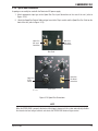
3.12 Inserting Wire into the Feedhead
WARNING
ELECTRIC SHOCK CAN KILL! Make certain the input power is disconnected from the power supply before
proceeding. Do not reattach the input power until told to do so in these instructions.
1. Loosen the Spring Pressure Adjusting Knob if needed and swing it down (First part of Figure. 3-10)
2. Move the Pressure (top) Roller Arm by swinging it to the right. (Second part of Figure. 3-10)
3. Make sure the end of the wire is free of any burrs and is straight. Pass the end of wire through the Inlet Wire
Guide and over the Feedroll. Make certain the proper groove is being used. (Second part of Figure. 3-10)
4. Pass the wire through the outlet guide and into the Gun liner of the Gun Cable. (Second part of Figure. 3-10)
5. Close the Pressure Roller Arm. (Figure. 3-11)
6. Swing the Spring Pressure Adjusting Knob back into place. (Figure. 3-11)
7. Use the Spring Pressure Adjusting Knob to create a “snug” condition. (Clockwise to tighten and Counter
Clockwise to loosen). (Figure. 3-11)
8. Figure 3-12 shows the result with wire installed. Continue to the next section for proper setting of tension.
1 - Loosen
Adjuster and
swing down
2 - Swing
Pressure arm
open
4 - Feed wire
through here
3 - Feed wire
through here
Art # A-07143
Figure 3-10: Opening Pressure Arm and Inserting Wire
7 - Adjust
the tension
5 - Swing
the Pressure
Arm closed
6 - Swing the
Adjuster back into
place.
Art # A-07144
Figure 3-11: Closing Pressure Arm and Adjusting Tension
August 22, 2008
3-11
FABRICATOR 251
Wheel Brake Hex Head Bolt
Pressure Adjustment
Device
Art # A-07162
Spool Hub Nut
Figure 3-12: Wire Installed
3.13 Wirefeeder Drive Roller Pressure Adjustment
The roller on the swing arm applies pressure to the grooved roller via an adjustable tension devise. The Tension
Adjuster should be set to a minimum pressure that will provide satisfactory wire feed without slippage. If slipping
occurs, and inspection of the wire out of the MIG gun reveals no deformation or wear, the conduit liner should be
checked for kinks or clogging from metal flakes. If this is not the cause of slipping, the feedroll pressure can be
increased by rotating the Tension Adjusting knob clockwise. The use of excessive pressure may cause rapid wear of
the feed roller, motor shaft and motor bearings.
NOTE
Genuine Valley National Gases contact tips and liners should be used. Many non-genuine liners use inferior
materials which can cause wire feed problems.
3.14 Wire Reel Hub Brake
The wire reel hub incorporates a friction brake which is adjusted during manufacture for optimum braking. If it is
considered necessary, adjustment can be made by turning the hex head bolt inside the open end of the wire reel hub.
Clockwise rotation will tighten the brake. (Refer to Figure 3-12 above).
CAUTION
Excessive tension on the brake will cause rapid wear of mechanical wire feed parts, over heating of electrical componentry and possibly an increased incidence of wire burnback into the contact tip.
NOTE
Correct adjustment will result in the wire reel circumference continuing no further than 0.75" (20mm) after
release of the Gun trigger switch. The wire should be slack without becoming dislodged from the reel.
3-12
August 22, 2008
FABRICATOR 251
3.15 Spool Gun Attachment
A spool gun can readily be used with the Fabricator 251 power supply.
1. Attach appropriate input gas to the Spool Gun Gas Input Connection on the rear of the unit (refer to
Figure. 3-13).
2. Attach the Spool Gun Control Cable and gas hose to the 10 pin socket and the Spool Gun Gas Outlet on the
front of the unit (refer to Figure. 3-13).
Main Gun
Gas Input
Connection
Spool Gun
Gas Input
Connection
Rear Panel
Spool Gun
Gas Outlet
Connection
Spool Gun
10 Pin
Socket
Front Panel
Art # A-08573
Figure 3-13: Spool Gun Connections
NOTE
When the SPOOL GUN is properly attached and the trigger is depressed, the system automatically disables
the internal wire feed and gas controls and selects the SPOOL GUN feeder and gas control.
August 22, 2008
3-13
FABRICATOR 251
3.16 Polarity Changeover
WARNING
ELECTRIC SHOCK CAN KILL! Make certain the input power is disconnected from the power supply before
proceeding. Do not reattach the input power until told to do so in these instructions.
The output terminals are located on the front panel of the welding power source.
CABLE TO GUN, CABLE TO WORK
CABLE CONNECTIONS
CABLE TO GUN
CABLE TO WORK
1. GMAW* – Steel, Stainless Steel,
1. Connected to (+) 1. Connected to (-)
1. D.C. Electrode Positive
Aluminum & gas shielded Flux
Pos. output
Neg. output
(DCEP) – Reverse Polarity
Cored electrode wires
terminal
terminal
2. Connected to (-) 2. Connected to (+)
2. FCAW* – Gasless Flux Cored
2. D.C. Electrode Negative
Neg. output
Pos. output
electrode wire
(DCEN) – Straight Polarity
terminal
terminal
* Exception - Contact your filler metal supplier for the recommended polarity.
PROCESS
POLARITY
Table 3-3: Process Cable Connections
Work Lead
Art # A-07163
Connected for D.C.
Electrode Positive
(DCEP) Welding
Figure 3-14: Polarity Connections for DCEP
3-14
August 22, 2008
FABRICATOR 251
Work Lead
Connected for D.C.
Electrode Negative
(DCEN) Welding
Art # A-07164
Figure 3-15: Polarity Connections for DCEN
Changing polarity process.
a. Locate the two terminal knobs at the front of the machine. Refer to Figures 3-14 and 3-15.
b. Remove both terminal knobs by rotating counterclockwise.
c. Set up the desired lead polarity as per Table 3-3 and as shown in Figures 3-14 or 3-15.
d. Place the Work Lead cable on the opposite terminal.
e. Replace both terminal knobs and tightly secure them to ensure good electrical connections.
CAUTION
Ensure terminal knobs are tightly secured and that there is no connection between positive and negative
terminals.
f. Reconnect the input power to the power supply.
August 22, 2008
3-15
FABRICATOR 251
NOTES:
3-16
August 22, 2008
FABRICATOR 251
SECTION 4:
OPERATION
WARNING
DO NOT TOUCH the electrode wire while it is being fed through the system. The electrode wire will be at
welding voltage potential.
4.01 Power Supply Controls, Indicators and Features
Thermal Overload Indicator
Digital Display
Voltage / Amp
Selection Button
Wire Feed Speed Control
A/V
Power On/Off Switch
Weldskill
Coarse Voltage Selector Switch
17V - 21V
Front Panel
Access Hole
Torch
13V - 16V
22V - 31V
Fine Voltage Selector Switch
Spool Gun Gas Outlet
Gun Switch
Amphenol
Receptacle
Spool Gun Interface
Amphenol Receptacle
Gun Polarity Lead
Negative Welding
Terminal
Positive Welding
Terminal
Art # A-08562
Figure 4-1: Fabricator Controls
August 22, 2008
4-1
FABRICATOR 251
On / Standby Power Switch
The indicator light is provided to indicate when the Fabricator 251 is connected to the Input Power Supply Voltage.
With the switch in the Standby position, the auxiliary power and the fan are turned off and the switch is illuminated.
WARNING
When the light is lit, the machine is connected to the Mains supply voltage and the internal electrical
components are at Mains voltage potential.
Digital Display
The Digital Display allows for accurate monitoring (5% tolerance) of welding current and voltage to facilitate
precise welding condition adjustments.
Value displayed for 21.9 Volts
Art # A-07279
Value displayed for 157 Amp
Figure 4-2: Digital Display
The Digital Meter will display both welding current or arc voltage. To toggle between the current and voltage
readings depress the push button switch mounted below the meter display.
The Digital Meter will hold the last reading at completion of welding for 10 seconds to allow for easy operator set
up.
4-2
August 22, 2008
FABRICATOR 251
Digital AMP Reading to IPM Conversion
STEEL
900
800
600
ST
EE
L)
500
400
300
L)
EE
(.0
23
-
Wire Speed (IPM)
700
30
T
-S
35
(.0
)
EL
(.0
TE
-S
(.045
200
EL)
- STE
100
0
25
50
75
100
125
150
175
200
225
250
275
Current (Amps)
300
325
Art # A-07451
Figure 4-3: Steel - AMP to IPM Conversion
STAINLESS STEEL
900
800
Wire Speed (IPM)
700
600
500
S)
400
23
-S
S)
S)
(.0
300
S
0-
3
(.0
5
.03
-S
(
S)
5-S
(.04
200
100
0
25
50
75
100
125
150
175
200
225
250
Current (Amps)
275
300
325
Art # A-07452
Figure 4-4: Stainless Steel - AMP to IPM Conversion
August 22, 2008
4-3
FABRICATOR 251
ALUMINUM
900
800
Wire Speed (IPM)
700
600
L)
A
0-
3
(.0
500
35
)
AL
(.0
400
(.047
- AL)
300
200
100
0
25
50
75
100
125
150
175
200
225
Current (Amps)
250
275
300
325
Art # A-07453
Figure 4-5: Aluminum - AMP to IPM Conversion
Thermal Overload
The critical components for thermal protection are the rectifier stack and the transformer, which are fitted with
thermal overload cut out devices. If the overload is activated then the machine should be left to cool for approximately
15 minutes before resuming welding. If the Power Source is operated within its duty cycle, the thermal overload
will not activate. Refer to section 2.09 for an explanation of duty cycle and section 2.10 for the power supply
specifications.
Wirespeed Control
The Wirespeed Control knob controls the welding current via the electrode wire feed rate, i.e. the speed of the wire
feed motor.
Coarse Voltage Control Switch
The Coarse Voltage Control sets the voltage level to the welding terminals as it is rotated in either direction. Clock
wise to increase.
Fine Voltage Control Switch
The Fine Voltage Control switch increases the voltage (in smaller increments than the Coarse switch) as it is
rotated in either direction. Clock wise to increase.
CAUTION
The Coarse & Fine Voltage Control switches MUST NOT BE SWITCHED during the welding process.
4-4
August 22, 2008
FABRICATOR 251
Positive and Negative Welding Current Terminals
Refer back to Figure 4-1. Both terminals located at
the bottom of the unit are shown without the terminal
knob. Both knobs must be firmly secured before
attempting to weld.
Spool Gun Interface Amphenol Connector
The Spool Gun Interface 10 pin connector is used to
connect a spool gun to the Fabricator 251 (refer to
Figure 4-7 and Table 4-1).
Gun Polarity Lead
This lead selects the welding voltage polarity of the
electrode wire. Attach it to the positive welding terminal
(+) when using steel, stainless steel or aluminium
electrode wire . Attach the Gun Polarity Lead to the
negative welding terminal ( - ) when using gasless
flux cored electrode wire. If in doubt, consult the
manufacturer of the electrode wire for the correct
polarity. Also refer to section 3-15.
E
F
D
J
G
H
C
I
A
B
Positive and Negative Welding Terminal Knobs
Welding current flows from the Power Supply via
heavy duty terminals. It is essential, that these terminal
knobs are tight to achieve the necessary electrical
connection.
CAUTION
Loose welding terminal connections can cause
overheating and result in failure of the
terminals.
Gun Switch Receptacle
The Torch Trigger 4-pin receptacle is used to connect
the two wires from the torch gun to the Fabricator
251. Only pins 1 and 2 are used for this.
To make connections, align keyway, insert plug, and rotate
threaded collar fully clockwise.
Art # A-07181
Figure 4-7: Spool Gun 10 pin Receptacle
To make connections, align keyway, insert plug, and
rotate threaded collar fully clockwise. The socket
information is included in the event the supplied cable
is not suitable and it is necessary to wire a plug or
cable to interface with the SPOOL GUN 10-pin
receptacle.
Socket Pin
A
B
C
D
E
F
G
1
2
H
I
J
Function
Not Used
Spool Gun Motor (-)
Spool Gun Motor (+)
Spool Gun Switch
Spool Gun Speed C.W.
Potentiometer
Spool Gun Speed Wiper
Potentiometer
Spool Gun Switch
Spool Gun Speed C.C.W.
Potentiometer
Not Used
Not Used
Table 4-1: 10-pin Receptacle Pin Functions
NOTE
Art # A-07171
Figure 4-6: Gun Switch Receptacle
August 22, 2008
When the SPOOL GUN is properly attached
and the trigger is depressed, the system
automatically disables the internal wire feed
and gas control and selects the SPOOL GUN
feeder and gas control.
4-5
FABRICATOR 251
4.02 Weld Mode Selector
The Weld Mode Selector switch selects the method of welding mode.
DWELL
(STITCH)
2
WELD
(SPOT / STITCH)
WELD MODE
SPOT
STITCH
2
4T
2T
3
1
4
MIN
3
1
4
MIN
t
t
BURNBACK
Art # A-07183
Figure 4-8: Internal Welding Controls
SPOT:
2T (Continuous Welding):
This mode of welding is used to weld two or more
components together with a continuous weld. When
the MIG gun trigger switch is depressed welding
commences. When the MIG gun trigger switch is
released welding ceases.
This mode of welding is used to weld two plates
together at a desired location by melting the top &
bottom plates together to form a nugget between
them. The spot time period is set by the Weld (Spot/
Stitch) control knob located in the electrode wire
compartment. (Refer to Figure 4-8 for control).
WELD MODE
SPOT
STITCH
4T
Art # A-07427
2T
Figure 4-9: For Reference only
Art # A-07466
Figure 4-10: Spot Weld
NOTE
A spot nozzle should be used on the MIG gun
to obtain consistent spot welds.
4-6
August 22, 2008
FABRICATOR 251
STITCH:
Dwell Stitch
This mode of welding is used to weld two or more
components together with a stitch weld. The WELD
(Spot/Stitch) shaft controls the welding or ‘ON’ time
and the "DWELL (Stitch)" shaft controls the interval
or ‘OFF’ time for stitch welding. (Refer to Figure 4-8
for control).
DWELL (STITCH) CONTROL KNOB
When the Weld Mode control is in the Stitch position, the
Dwell (Stitch) knob controls the length of the non-weld
portion of stitch welding.
DWELL
(STITCH)
2
3
Art # A-07428
Figure 4-11: Stitch Welding
4T (Latch):
Art # A-07430
1
4
MIN
t
Figure 4-14: Dwell (Stitch) Control
Burnback Control
This mode of welding is mainly used for long weld
runs, as the operator need only press the trigger to
activate the weld, then press the trigger again to stop.
This replaces the need for the operator to depress
and hold the trigger for the complete length of the
weld run.
WELD MODE
SPOT
Burnback time is the difference between the wirefeed
motor stopping and the welding current ceasing. The
Burnback time allows the electrode wire to burn out
of the molten metal weld pool. The Burnback time is
factory set for optimum performance. Burnback time
is adjusted by the knob of the potentiometer.
Clockwise adjustment increases Burnback time.
STITCH
4T
BURNBACK
Art # A-07431
Art # A-07427
2T
Figure 4-12: For Reference only
Figure 4-15: Burnback Control
WELD (Spot/Stitch)
WELD MODE - SPOT
When the Weld Mode control is in the Spot position,
the Weld (Spot/Stitch) knob controls the duration of
a single spot weld.
WELD MODE - STITCH
When the Weld Mode control is in the Stitch position,
the Weld (Spot/Stitch) knob controls the length of
the stitch weld.
WELD
(SPOT / STITCH)
2
3
Art # A-07429
1
4
MIN
t
Figure 4-13: Weld (Spot/Stitch) Control
August 22, 2008
4-7
FABRICATOR 251
4.03 400 Amp Air-Cooled MIG Gun
The Valley National Gases air-cooled 43340VNG 400 amp MIG gun fitted to the FABRICATOR 251 offers robust
construction, unparalleled reliability and easy replacement of consumable parts. The Air-Cooled MIG Gun has an
operating capacity in excess of the capacity of the FABRICATOR and can be expected to give trouble free service.
6
5
7
4
3
2
1
Art # A-08563
Figure 4-16: Valley National Gases 43340VNG Air-Cooled MIG Gun
Item
1
2
3
4
5
6
7
Original Parts Installed
Description
Part No.
NOZZLE
VNG24A-62
NOZZLE INSULATOR
VNG34A
CONTACT TIP
VNG14-35
GAS DIFFUSER
VNG54A
CONDUCTOR TUBE
WM63J-50
HANDLE ASSY
WM480
TRIGGER ASSY
WM92
Qty
1
1
1
1
1
1
1
Table 4-2: Original Consumable MIG Gun Parts
Additional Gun Consumable Parts
See the Valley National Gases Air-Cooled Mig Guns Manual #89260000 that came with the included MIG gun.
4-8
August 22, 2008
FABRICATOR 251
4.04 Installing A New Wire Conduit
1. Be sure the MIG gun cable is arranged in a straight line, free from twists, when installing or removing a wire
conduit. Remove the old conduit by first removing the MIG gun nozzle, contact tip, insulator and gas diffuser.
Then loosen Allen screws in the conductor tube and connector plug and pull the old wire conduit out of the
cable assembly from the connector plug end.
2. To install a new conduit, first inspect the o-ring gas seal on the conduit for cuts or damage. Start from the
connector plug end of the assembly and begin pushing the conduit through the connector plug, cable assembly
and into the gun. If the conduit should lodge along the way, gently whip or work the cable assembly to aid
forward movement.
When the conduit stop meets the end of the connector plug and the new raw end extends through the end of
the conductor tube on the welding gun, tighten the Allen screw in the connector plug onto the conduit to
prevent its backward movement.
CONDUCTOR TUBE
CONDUIT LINER
ALLEN SCREW
REMOVE
CONSUMABLES
1 1/16"
(27mm)
Art # A-08565
O-RINGS
ALLEN SCREW
CONDUIT LINER
CONNECTOR PLUG
Figure 4-17: Conduit Trim Length
NOTE
When the conduit is fully inserted into the cable assembly and the conduit stop is firmly against the
Connector Plug, the “raw end” of the conduit will protrude out of the open end of the gun conductor tube.
Trim the conduit as shown in Figure 4-14. The trimmed end which seats in the Gas Diffuser must be filed
and reamed smooth on the inside and outside radii so wire feed will not be obstructed.
3. Replace Gas Diffuser, Contact Tip, Insulator and Nozzle.
4. Tighten the Allen screw in the conductor tube.
CAUTION
Do not over tighten the conductor tube screw as this action will result in the distortion of the conduit and
will lead to wire feedability problems.
August 22, 2008
4-9
FABRICATOR 251
4.05 MIG Gun Maintenance
Remove dust and metallic particles from the gun conduit by forcing clean, dry compressed air into the conduit once
a week. This will minimize wire feeding problems.
4.06 Basic Welding Technique
Setting of the Power Supply
The setting of the Fabricator 251 requires some practice by the operator, in that the welding power supply has two
control settings that have to balance. These are the Wire Speed Control and the Voltage Control Switches. The welding
current is determined by the Wire Speed Control, the current will increase with increased Wire Speed, resulting in a
shorter arc. Less wire speed will reduce the current and lengthen the arc. Increasing the welding voltage hardly alters
the welding current level, but lengthens the arc. By decreasing the voltage, a shorter arc is obtained with little change
in welding current.
When changing to a different electrode wire diameter, different control settings are required. A thinner electrode wire
needs more Wire Speed to achieve the same current level.
A satisfactory weld cannot be obtained if the wire speed and voltage switch settings are not adjusted to suit the
electrode wire diameter and dimensions of the work piece.
If the Wire Speed is too high for the welding voltage, “stubbing” will occur as the wire dips into the molten pool and
does not melt. Welding in these conditions normally produces a poor weld due to lack of fusion. If, however, the
welding voltage is too high, large drops will form on the end of the electrode wire, causing spatter. The correct setting
of voltage and Wire Speed can be seen in the shape of the weld deposit and heard by a smooth regular arc sound.
MIG Gun Travel Speed
Speed at which a weld travels influences the width of the weld and penetration of the welding run.
Position of MIG gun
The angle of MIG gun to the weld has an effect on the width of the weld run. Refer to Figure 4-15.
Forehand
Vertical
Art # A-05148
Figure 4-18: MIG Gun Angle
Distance from the MIG Gun Nozzle to the Work Piece
The electrode stick out from the MIG gun nozzle should be between 5/64" (2.0mm) to 13/64" (5.0mm). This distance
may vary depending on the type of joint that is being welded.
4-10
August 22, 2008
FABRICATOR 251
Flux Cored Wire
Solid Wire
1/4”
(6.4mm)
5/16”
(7.9mm)
3/8”
.030”
(.8mm)
.023”
(.6mm)
(9.5mm)
11/16”
(17.5mm)
9/16”
(14.3mm)
.035”
(.9mm)
.035”
(.9mm)
Gas
Nozzle
Contact
Tip
Art # A-07186
Distance: ±1/16”
.045”
(1.1mm)
Wire Diameter
Figure 4-19: Optimum Contact Tip to Work Distances
Electrode Wire Size Selection
The choice of electrode wire size in conjunction with shielding gas used depends on:
- Thickness of the metal to be welded,
- Type of joint,
- Capacity of the wire feed unit and power supply,
- The amount of penetration required,
- The deposition rate required,
- The bead profile desired,
- The position of welding and
- Cost of the electrode wire.
Weld metal deposition rate is proportional to current density. Current density is defined as the current per cross
sectional area of the electrode wire and is normally expressed as amps per mm2. An example is in Table 4-3 below.
Electrode Wire Size Current (Amps) Current Density(Amps/mm2)
.035”( 0.9mm)
200
314
.045”(1.2mm)
200
177
Deposition Rate(lbs/hour)
7.0
6.2
Table 4-3: .035"(0.9mm) , .045"(1.2mm) Wire Deposition Rate
Advantages of MIG welding forehand:
- Allows superior visibility of the weld zone
- Flatter weld bead
- Shallower penetration
Forehand
Vertical
Backhand
Art # A-07185
Figure 4-20: MIG Gun Angle
August 22, 2008
4-11
FABRICATOR 251
4.07 Stitch Welding Operation
Welding consumable costs can be reduced by replacing a continuous weld bead with the Stitch weld bead. It will
also reduce heat distortion in thin plate.
Coarse & Fine Voltage Selector Switches and Wire Speed Control
Set these controls to obtain the desired welding conditions for the wire and material being welded.
Mode Selector Switch
Set the WELD MODE switch to STITCH.
WELD (Spot/Stitch) Time
Adjust the WELD (Spot/Stitch)control knob for the desired weld or ‘ON’ time while stitch welding.
Dwell Time
Adjust the DWELL (Stitch) control knob for the desired interval or ‘OFF’ time while stitch welding.
4.08 Spot Welding Operation
Fit an optional spot welding nozzle to the MIG gun
for consistent spot welding operations. Refer to the
Spot Welding Nozzle table. The Fabricator 251 will
operate effectively using .030” (0.8mm) electrode
wire when spot welding. Penetration depth is limited
when using .024”(0.6mm) electrode wire for spot
welding. Set the controls as follows for spot welding:
SPOT WELDING NOZZLES
TYPE
Flat Arc Spot
Coarse & Fine Voltage Selector Switches and
Wirespeed Control
Select higher Voltage Selector switch positions and
set the Wirespeed Control between 354 to 590 ipm
(9 to 15 m/min) for maximum penetration.
Inside Corner Arc Spot
Mode Selector Switch
Set the WELD MODE switch to SPOT.
Outside Corner Arc Spot
Spot Time
Adjust the WELD (Spot/Stitch) control knob for the
desired weld or ‘ON’ time for spot welding.
Automotive Stud Nozzle
NO.4 400 AMP
24A-62-FAS
1240-1520 (5/8"
Bore)
24A-75-FAS
1240-1530 (3/4"
Bore)
24A-100-FAS
1240-1550
(1" Bore)
24A-75-IAS
1240-1531
(3/4” Bore)
24A-75-IAS
1240-1532
(3/4” Bore)
N/A
Dwell Time
The DWELL (Stitch) control knob has no affect in
this mode of operation.
4-12
Table 4-4: Spot Welding Nozzles
August 22, 2008
FABRICATOR 251
4.09 Gas Selection for Gas Metal Arc Welding
Suggested
Shielding
Gas
Metal Type
Base Plate
Thickness
Filler
Metal
Transfer
Mode
Carbon
Steel
Greater than 22
gauge (.030”)
ER70S-X
Short
Circuit
100% CO2
All
Position
Welding
High welding speeds. Good
penetration and pool control.
Greater than 22
gauge (.030”)
ER70S-X
Short
Circuit
75% Argon
25% CO2
Suitable for high-current and highspeed welding.
Greater than 22
gauge (.030”)
ER70S-X
Short
Circuit
92% Argon
8% CO2
All
Position
Welding
All
Position
Welding
Greater than 10
gauge (1/8”)
ER70S-X
Spray
Transfer
92% Argon
8% CO2 or
minimum
80% Argon
20% O2
75% Argon
25% CO2
Flat & HV Good arc stability, weld soundness,
Fillet
and increasing width of fusion.
Short
Circuit
92% Argon
8% CO2
All
Position
Welding
Spray
transfer
92% Argon
8% CO2 or
minimum
80% Argon
20% O2
98% Argon
2% CO2
Flat & HV Reduces undercutting. Higher
Fillet
deposition rates and improved bead
wetting. Deep penetration and good
mechanical properties.
Low Alloy Greater than 22 See * below
Short
and High gauge (.030”)
Circuit
Alloy Steel
Globular
Greater than 22 See * below
gauge (.030”)
Greater than
3/32”
See * below
Greater than 14 See * below
gauge (.075”)
Stainless Greater than 22
gauge (.030”)
Steel
Greater than
3/32”
Aluminum Greater than 18
gauge (.045”)
Short
Circuit
ER308-X
ER309-X
ER316-X
Short
Circuit
90% Helium
7.5% Argon
2.5% CO2 or
81% Argon
18% Helium
1 % CO2
ER308-X
ER309-X
ER316-X
Spray
Transfer
ER4043
ER5356
Spray
Transfer
90% Helium
7.5% Argon
2.5% CO2 or
81% Argon
18% Helium
1 % CO2
Argon
Welding
Positions
All
Position
Welding
All
Position
Welding
Comments
Higher deposition rates without meltthrough. Minimum distortion and
spatter. Good pool control for out-ofposition welding.
High welding speeds. Good
penetration and pool control.
Applicable for out-of-position welds.
Suitable for high-current and highspeed welding.
Good coalescence and bead contour.
Good mechanical properties.
Good control of melt-through and
distortion. Used also for spray arc
welding. Pool fluidity sometimes
sluggish depending on the base alloy.
All
Position
Welding
Low CO2 percentages in Helium mix
minimizes carbon pickup, which can
cause intergranular corrosion with
some alloys. Helium improves wetting
action and contour. CO2 percentages
above 5% should be used with
caution on some alloys.
Flat & HV Good arc stability. Produces a fluid
Fillet
but controllable weld pool, good
coalescence, and bead contour.
Minimizes undercutting on heavier
thickness.
All
Excellent cleaning action. Provides
Position more stable arc than helium-rich
Welding mixtures.
* Contact your Filler Metal Supplier for recommended filler metal for the base metal to be welded.
Table 4-5: Gas Selection Chart
August 22, 2008
4-13
FABRICATOR 251
4.10 Welding Setting Selection Guide
Material Type
Wire Type
Shielding Gas
and Flow Rate
100% CO2
25cfh
Wire Size
(Diameter)
.035” (0.9mm)
.045” (1.2mm)
.023” (0.6mm)
Solid
(or hard)
Steel
75% Ar 25%
CO2 ,25cfh
.030” (0.8mm)
.035” (0.9mm)
.045” (1.2mm)
ER70S-6
.023” (0.6mm)
92% Ar
8% CO2
.030” (0.8mm)
.035” (0.9mm)
.045” (1.2mm)
100% CO2
25cfh
.045” (1.2mm)
1/16” (1.6mm)
Flux Core
E71T-1
E71T-GS
E71T-11
Steel
.030” (0.8mm)
.035” (0.9mm)
None
.045” (1.2mm)
1/16” (1.6mm)
.030” (0.8mm)
Aluminum
Art # A-07439
Aluminum
Stainless
Steel
4043 ER
5183 ER
5356 ER
100% Ar
25cfh
Stainless
7.5% Ar
90% He
2.5% CO2
35cfh
ER308LSi
ER309LSi
ER316LSi
.035” (0.9mm)
.045” (1.2mm)
.030” (0.8mm)
.035” (0.9mm)
Table 4-6: Welding Setting Selection Guide
4-14
August 22, 2008
FABRICATOR 251
Coarse
Voltage
THICKNESS**
Coarse Voltage
Fine Voltage
Step
Wire
Speed
H
Fine
Voltage
22 ga. (0.8mm) 18 ga. (1.2mm) 16 ga. (1.6mm) 1/8” (3.2mm)
M/2
1.5
M/3
M/5
L/6
L/6
1.5
1.5
M/1
M/1
M/1
2.25
2
1.5
M/1
M/3
M/4
L/8
L/8
L/8
2.25
1.25
M/1
M/2
M/1
2.75
1.75
1.25
M/2
M/3
M/4
L/8
M/6
H/1
L/5
1.5
L/6
L/8
M/1
1.5
1.75
3
3
2.5
1.5
4.5
2.5
2.5
1.5
2
1.5
1.75
2
1
M/4
M/7
M/4
M/7
M/5
M/5
M/5
M/6
M/5
M/6
M/7
H/2
M/2
L/8
M/4
M/7
L/8
L/7
4.5
3.25
M/2
L/8
4.25
4
M/5
M/5
M/6
M/2
1.5
M/3
M/3
2.5
2
M/4
M/4
3
2.5
M/7
M/6
2
2
1/4” (6.4mm)
3/8” (9.5mm) 1/2” (12.7mm) 5/8” (15.9mm)
H/1
H/3
H/2
5
3.5
H/3
6
3.5
H/4
H/5
8.5
4.25
H/5
H/7
7.25
4.5
4.5
4
3.25
2
6
4.5
3
2.25
2.25
2
2.75
2
2
1
5
4.5
3
5
3.5
M/8
M/7
M/8
H/2
H/3
H/4
H/4
H/1
H/4
M/5
M/4
M/7
H/2
H/1
H/2
H/2
H/1
H/1
5.25
5.75
3
H/1
H/1
H/2
7
6.75
4.25
H/3
H/3
H/4
8.25
8
5
H/4
H/5
5.75
4.5
7.75
5.75
5.5
3
4
H/4
H/5
H/5
H/4
6.5
7
3.25
5.5
H/5
H/7
H/6
H/4
7.25
7.5
3.5
5.5
H/5
7
2.75
6
3.5
3.25
1.5
M/8
M/6
M/8
H/3
7.5
4.5
3.75
M/8
M/8
5.5
3.75
M/8
H/4
5.5
4.5
2.5
7
6.75
3.5
6.5
4.5
H/3
H/4
H/6
H/1
7.75
5
6
6
H/5
H/7
H/5
5.75
H/6
6.25
6.5
6
H/6
6.5
Table 4-6: Welding Setting Selection Guide
August 22, 2008
4-15
Art # A-07439
M
L
FABRICATOR 251
NOTES
4-16
August 22, 2008
FABRICATOR 251
SECTION 5:
MAINTENANCE & TROUBLESHOOTING
5.01 Routine Maintenance & Inspection
The only routine maintenance required for the Fabricator 251 is a thorough cleaning and inspection, with the frequency
depending on the usage and the operating environment.
WARNING
Disconnect the Fabricator from the Input power supply voltage before disassembling.
Special maintenance is not necessary for the control unit parts in the Power Supply. If these parts are damaged for any
reason, replacement is recommended.
CAUTION
Do not blow air into the Power Supply during cleaning. Blowing air into the Power Supply can cause metal
particles to interfere with sensitive electronic components and cause damage to the Power Supply.
To clean the Power Supply, disconnect it from the mains supply voltage then open the enclosure and use a vacuum
cleaner to remove any accumulated dirt and dust. The Power Supply should also be wiped clean. If necessary, solvents
that are recommended for cleaning electrical apparatus may be used.
Troubleshooting and repairing the Fabricator should be carried out only by those who are familiar with electrical
equipment.
WARNING
Do not attempt to diagnose or repair unless you have had training in electronic measurement and
troubleshooting techniques.
August 22, 2008
5-1
FABRICATOR 251
Warning!
Disconnect input power before maintaining.
Maintain more often
if used under severe
conditions
Each Use
Visual check of torch
Consumable parts
Visual check of
regulator and pressure
Weekly
Visually inspect the torch
body and consumables
Visually inspect the
cables and leads.
Replace as needed
3 Months
Replace all
broken parts
Gas lines
Clean exterior
of power
supply
6 Months
Visually check and
use a vacuum to carefully
clean the interior
Art # A-07269
5-2
August 22, 2008
FABRICATOR 251
5.02 Basic Troubleshooting
The basic level of troubleshooting is that which can be performed without special equipment or knowledge, and
without removing the covers from the Power Supply.
If major components are faulty, then the Power Supply should be returned to an accredited Valley National Gases
Service Agent for repair.
5.03 Solving Problems Beyond the Welding Terminals
The general approach to fix GMAW/FCAW problems is to start at the wire spool then work through to the MIG torch.
There are two main areas where problems occur:
Porosity
When there is a gas problem the result is usually porosity within the weld metal. Porosity always stems from
some contaminant within the molten weld pool which is in the process of escaping during solidification of the
molten metal.
Contaminants range from no gas around the welding arc to dirt on the work piece surface. Porosity can be
reduced by checking the following points:
FAULT
CAUSE
1. Gas cylinder
contents and flow meter
2. Gas leaks
3. Internal gas hose in
the power supply
Porosity
4. Welding in a windy
environment
5. Welding dirty, oily,
painted, oxidized or
greasy plate.
6. Distance between the
MIG torch nozzle and
the work piece.
7. Maintain the MIG
torch in good working
order.
REMEDY
a. Ensure that the gas cylinder is not
empty and the flow meter is correctly
adjusted to 25CFM (15 litres per minute)
a. Check for gas leaks between the
reulator/flowmeter connection and in the
gas hose to the power supply
a. The hose from the solenoid valve to
the MIG torch adaptor may be fractured
or disconnected from the MIG torch
adaptor. Return to an accredited Valley
National Gases Service Agent for repair.
a. Shield the weld area from the wind or
increase the gas flow
a. Clean contaminates off the plate
a. Keep the distance between the MIG
torch nozzle and the work piece to a
minimum.
a. Ensure that the gas holes are not
blocked and gas is exiting out of the
torch nozzle. Refer to WARNING below
b. Do not restrict gas flow by allowing
spatter to build up inside the MIG torch
nozzle.
C. Check that the MIG gun O-rings are
not damaged.
Table 5-1: Porosity Problems
August 22, 2008
5-3
FABRICATOR 251
WARNING
Disengage the drive roll when testing for gas flow by ear.
2. Inconsistent wire feed
FAULT
CAUSE
1. Wire spool brake is
too tight.
2. Wire spool brake is
too loose.
3. Worn or incorrect
feed roller size.
4. Misalignment of
inlet/outlet guides.
Inconsistent
Wire Feeding
5. Liner blocked with
swarf.
6. Incorrect or worn
contact tip.
7. Poor work lead
contact to work
piece.
8. Bent liner.
REMEDY
a. Feed roller driven by motor in the cabinet will slip.
a. Wire spool can unwind and tangle
a. Use ‘U’ groove drive feed roller matched to the aluminum wire
size you are welding.
b. Use ‘V’ groove drive feed roller matched to the steel wire size
you are welding.
C. Use ‘knurled V’ groove drive feed roller matched to the flux cored
wire size you are welding.
a. Wire will rub against the misaligned guides and reduces wire
feedability.
a. Swarf is produced by the wire passing through the feed roller,
if excessive pressure is applied to the pressure roller adjuster.
Swarf can also be produced by the wire passing through an
incorrect feed roller groove shape or size. Swarf is fed into the
liner where it accumulates thus reducing wire feedability.
a. The contact tip transfers the weld current to the electrode wire.
If the hole in the contact tip is too large then arcing may occur
inside the contact tip resulting in the electrode wire jamming in
the contact tip. When using soft electrode wire such as
aluminum it may become jammed in the contact tip due to
expansion of the wire when heated. A contact tip designed for
soft electrode wires should be used.
a. If the work lead has a poor electrical contact to the work piece
then the connection point will heat up and result in a reduction
of power at the arc.
a. This will cause friction between the wire and the liner thus
reducing wire feedability
Table 5-2: Trouble Shooting for Inconsistent Wire Feed
5-4
August 22, 2008
FABRICATOR 251
5.04 Welding Problems
FAULT
A. Undercut
CAUSE
1. Welding arc voltage
too high.
REMEDY
a. Reduce voltage by reducing the voltage
selection switch position or increase the
wire feed speed.
2. Incorrect torch
angle
3. Excessive heat
input
a. Adjust angle
4. Weld speed too fast
B. Lack of penetration
1. Welding current too
low
a. Increase welding current by increasing
wire feed speed and increasing voltage
selection switch position.
2. Joint preparation too
narrow or gap too
tight
3. Shielding gas
incorrect
4. Weld speed too fast
1. Voltage too low
a. Increase joint angle or gap
C. Lack of fusion
2. Weld speed too fast
1. Voltage too high
D. Excessive spatter
2. Voltage too low
3. Weld speed too fast
1. Incorrect voltage and
current settings.
Convex, voltage too
low. Concave, voltage
too high.
E. Irregular weld
shape
a. Increase the torch travel speed and/or
reduce welding current by reducing the
voltage selection switch position or
reducing the wirefeed speed.
a. Reduce weld speed.
a. Change to a gas which gives higher
penetration
a. Reduce weld speed.
a. Increase voltage by increasing voltage
selection switch position.
a. Reduce weld speed.
a. Lower voltage by reducing the voltage
selection switch or increase wirespeed
control.
a. Raise voltage by increasing the voltage
selection switch or reduce wirespeed
control.
a. Reduce weld speed.
a. Adjust voltage and current by adjusting
the voltage selection switch and the
wirespeed control.
2. Wire is wandering
a. Replace contact tip
3. Incorrect shielding
gas
4. Insufficient or
excessive heat input
5. Weld speed too fast
a. Check shielding gas.
a. Adjust the wire speed control or the
voltage selection switch.
a. Reduce weld speed.
Table 5-3a: Welding Problems and Solutions
August 22, 2008
5-5
FABRICATOR 251
FAULT
CAUSE
1. Weld beads are too
small
2. Weld penetration
narrow and deep
A. Weld cracking
3. Excessive weld
stresses
4. Excessive voltage
5. Cooling rate too fast
6. Weld speed too fast
1. Faulty rectifier unit
B. Cold weld puddle
C. Arc does not have a
crisp sound that
short arc exhibits
when the wirefeed
speed and voltage
are adjusted
correctly.
2. Loose welding cable
connection.
3. Low Primary Voltage
4. Weld speed too fast
1. The MIG torch has
been connected to
the wrong polarity on
the front panel.
2. Weld speed too fast
REMEDY
a. Decrease travel speed
a. Reduce current and voltage and increase
MIG torch travel speed or select a lower
penetration shielding gas.
a. Increase weld metal strength or revise
design
a. Decrease voltage by reducing the
voltage selection switch.
a. Slow the cooling rate by preheating part
to be welded or cool slowly.
a. Reduce weld speed.
a. Have an accredited Valley National
Gases Service Agent to test then replace
the faulty component.
a. Check all welding cable connections.
a. Contact supply authority
a. Reduce weld speed.
a. Connect the MIG torch to the positive
(+) welding terminal for solid wires and
gas shielded flux cored wires. Refer to
the electrode wire manufacturer for the
correct polarity.
a. Reduce weld speed.
Table 5-3b: Welding Problems and Solutions (continued)
5-6
August 22, 2008
FABRICATOR 251
5.05 Power Supply Problems
FAULT
A. Indicator light is ON but welding
arc can not be established.
B. Mains supply voltage is ON.
Indicator light is not lit and
welding arc can not be
established.
CAUSE
1. Power On/Standby switch
in standby position.
1. Primary fuse is blown.
2. Broken connection in
primary circuit.
C. Mains indicator light is not lit
but welding arc can be
established.
D. Mains supply voltage is ON and
Indicator light is lit but when the
gun trigger switch is depressed
nothing happens.
1. Indicator light is open
circuit.
E. Mains supply voltage is ON, no
wire feed but gas flows from the
MIG Gun when the gun trigger
switch is depressed.
F. Wire feeds when the gun trigger
switch is depressed but arc can
not be established.
G. Wire continues to feed when the
gun trigger switch is released.
H. Jerky wire feed
1. Gun trigger switch leads
are disconnected.
1. Electrode wire stuck in
conduit liner or contact tip
(burn-back jam).
2. Faulty control PCB or MIG
Gun
1. Poor or no work lead
connection.
1. The Weld Mode Switch has
been set to 4T (latch
operation).
1. Worn or dirty contact tip
2. Worn feed roll
3. Excessive back tension
from wire reel hub roll.
4. Worn, kinked or dirty
conduit liner
5. Low Swing Arm pressure
1. Gas hose is cut or pinched
2. Gas passage contains
impurities
I. No gas flow
3. Gas regulator turned off
4. Gas cylinder is empty
J. Gas flow continues after the gun
trigger switch has been
released.
1. Gas valve has jammed
open due to impurities in
the gas or the gas line.
REMEDY
a. Switch the power On/Standby
switch to the “On” position .
a. Replace primary fuse.
a. Have an accredited Valley
National Gases Service Agent
check primary circuit.
a. Have an accredited Valley
National Gases Service Agent
replace Indicator light.
a. Reconnect.
a. Check for clogged / kinked MIG
Gun conduit or worn contract
tip. Replace faulty
component(s).
a. Have an accredited Valley
National Gases Service Agent
investigate the fault.
a. Clean work clamp area and
ensure good electrical contact.
a. Set the Weld Mode Switch to 2T
(normal operation).
a. Replace
a. Replace
a. Reduce brake tension on spool
hub
a. Clean or replace conduit liner
a. Increase the Swing Arm
pressure.
a. Check hose and replace or
repair.
a. Disconnect gas hose from the
rear of Fabricator then raise gas
pressure and blow out the
impurities.
a. Turn on.
a. Check cylinder volume and
replace or refill as needed.
a. Have an accredited Valley
National Gases Service Agent
repair or replace gas valve.
Table 5-4: Power Supply Problems
August 22, 2008
5-7
FABRICATOR 251
NOTES
5-8
August 22, 2008
FABRICATOR 251
APPENDIX 1: FEEDROLL KITS
DRIVE ROLL KITS (#375980-Series) 2 ROLL
Style 1
Style 2
Flat
Double
Smooth "V"
Flat Knurled
Double
Smooth "V"
Hard
Hard
.023" / 0.6mm
375980-031
-
-
-
-
-
.030", .035" / 0.8, 0.9mm
375980-001 375980-003
375980-010
-
-
-
.030", .035", .045" / 0.8, 0.9, 1.2mm
375980-028* 375980-029
-
-
-
-
.035" / 0.9mm
375980-040*
-
-
-
-
375980-032
-
-
375980-030
-
-
-
-
375980-092
375980-022
-
Top
Bottom
Wire Type
Style 3
Double Smooth
"V"
Double Smooth
"V"
Style 4
Double
Knurled "V"
Double
Knurled "V"
Soft/Hard/Tubular Hard/Tubular
Style 5
Style 6
Double Cog
Double "U"
Double Cog
Double "U"
Tubular
Soft (Aluminum)
Wire Size
.035", .045" 3/64" / 0.9, 1.2, 1.2mm
.045" / 1.2mm
3/64 / 1.2mm
.052" / 1.3mm
.052", 1/16" / 1.3, 1.6mm
375980-002* 375980-004
-
-
375980-011
-
-
375980-033
375980-090*
-
375980-012
-
-
-
375980-017
375980-023
-
Notes: 1) One Kit (# 375980-028) is supplied standard w ith each w ire feeder.
2) Drive Roll Kits include: Drive Rolls; Input & Output Guides
3) Narrow 30° "V"
August 22, 2008
A-1
FABRICATOR 251
APPENDIX 2: POWER SUPPLY CIRCUIT DIAGRAM
• Note the model and part number shown on the equipment nameplate
4 BLUE
SW2
COARSE
4A BLUE
FABRICATOR 251
8&8A BRN
(2)
(1)
(4)
(3)
8 BRN
(10)
(9)
9 BLK
(12)
(11)
10 RED
10C RED
(6)
11 GRY
(24) (23)
12 BRN
(18) (17)
16 WHT
(22) (21)
W1
Input Ter minal Block
L1
White
1
10&10A RED
T1
K1\3
1D RED [5]
1B RED
L2
Black
L1
1 RED
9&9A BLK
(8) (7)
10B RED
[6] 4C BLUE
(5)
11&11A GRY
K1\2
1C RED [3]
[4] 4B BLUE
(12) (11)
K1\1
2
2& 2A PNK
2B PNK
1A RED
2A
L3 [1]
(6) (5)
16&16A WHT
(10) (9)
CB1
Earth
Green\Yell ow
12&12A BRN
[2] T3
CONTACTOR
24V 50/ 60Hz
17&17A BLK
31 E ORN
3 ORN
(8) (7)
SW1
(20) (19)
(4) (3)
17 BLK
(16) (15)
13 VIO
(14) (13)
13&13A VIO
SW3
FINE
2 & 2A PNK
7C
33 BLU
X1/5
X1/6
X1/4
SOL1
31C ORN
PCB 3
7978034
X3/6
31 ORN
36 GRY
TS2
TEMP
LED1
X2 /5
56 RED
TS1
37 ORN
J A /7
35 WHT
J E /2
34 BLU
J E /1
30 A BRN
32 WHT
J B /4
J B /1 1
J B /5
J B /1 0
30 BRN
BURNBACK
100K
J A /1
Tri gger
R2
54 BLK
X3 /1
Torch
59 GRY
X3 /2
58 BRN
31D ORN
X2 /4
X3/5
30B BRN
30C BRN
230VAC
J A /2
31 A ORN
NORM
Sol enoid
4
BLUE
38 A WHT
Y1
15&15A ORN
3
BLUE
J A /5
24V Aux
208VAC
38 WHT
Sol enoid
14&14A BLU
39 RED
31 B ORN
M1
SPOOL
32 B WHT
Fan motor
Voltage T erminal block
60 RED
SOL2
J A /6
Y2
6
32 A WHT
5
7B
BLU
BLU
Input Ter minal Block
(2) (1)
M a in P C B 7977964 ( P C B1)
Art # A-07223
A-2
August 22, 2008
FABRICATOR 251
SWITCH 2 COARSE
1 3 5
7
POSITI ON
4
2
S2 T1
1
2
3
8
6
X
X
X
9
11
10 12
X
X
SWITCH 3 FI NE
1 3 5
7
2
8
SWI TCH
POSITI ON
1
2
3
4
5
6
7
8
X
T2
BR1
4
6
X
X
X
X
X
X
X
X
X
X
X
X
S3
11
13 15 17 19
23
24
X
X
+
Varis tor
+ C1-C4
VR1
22 VIO
23 GRY
C5
4 x 2 2, 000 uF
T4
F4
T5
PLUGSOCKET
X1/6
X1/5
X1/4
PCB 4
X1/3
DIG METER
30C BRN
704883
31D ORN
5A
X1/1
CB2
F3
SHUNT
47 GRY
PLUGSOCKET
55 BLK
S1
230V
TRANS 251US COIL
52 A BRN
53 WHT
45 VIO
49 A BLU
57 VIO
T1
208V
RI
WIRESPEED
1K
X3/4
X3/3
X2/3
X2/1
X2/2
X1/1
X1/2
50 VIO
52 BRN
J B /2
51 ORN
J B /1
49 BLU
J B /3
47 GRY
48 ORN
J B /9
J B /7
43 BLK
44 BRN
J B /6
JD-2
Wi re Feeder Motor
J B /8
JD-1
M2
M IG T imer P CB
7 9 7 7 9 6 5 (P CB 2 )
+ 46 RED
-
X1/3
JUMPER
NOTE:
Remove this jumper and use these pins when connecting
a replacement 7977964 Control PCB
August 22, 2008
NEGATIVE
OUTPUT
TERMINAL
J1
A
B
C
D
E
F
G
H
I
J
18-1SF
43A BLK
0V F1
POSITIVE
OUTPUT
TERMINAL
21 ORN
48 ORN
S4
0.1uF 630V
Induct or
T3
9
L1
Bridge Recti fier
F2
21
10 12 14 16 18 20 22
X X
X
X
X
X
X X
X
X
X
X
X
X
X
X
X
X
JC
Art # A-07223
A-3
LIMITED WARRANTY
August 2008
LIMITED WARRANTY:
The Manufacturer, warrants to customers of authorized
distributors ("Purchaser") that its products will be free of defects in workmanship or
material. Should any failure to conform to this warranty appear within the warranty period
stated below, the Manufacturer shall, upon notification thereof and substantiation that the
product has been stored, installed, operated, and maintained in accordance with the
Manufacturer's specifications, instructions, recommendations and recognized standard
industry practice, and not subject to misuse, repair, neglect, alteration, or damage, correct
such defects by suitable repair or replacement, at the Manufacturer's sole option, of any
components or parts of the product determined by the Manufacturer to be defective.
This warranty is exclusive and in lieu of any warranty of
merchantability, fitness for any particular purpose, or other warranty of
quality, whether express, implied, or statutory.
Limitation of liability: The Manufacturer shall not under any circumstances be liable for
special, indirect, incidental, or consequential damages, including but not limited to lost
profits and business interruption. The remedies of the purchaser set forth herein are
exclusive, and the liability of the Manufacturer with respect to any contract, or anything
done in connection therewith such as the performance or breach thereof, or from the
manufacture, sale, delivery, resale, or use of any goods covered by or furnished by the
Manufacturer, whether arising out of contract, tort, including negligence or strict liability,
or under any warranty, or otherwise, shall not exceed the price of the goods upon which
such liability is based.
No employee, agent, or representative of the Manufacturer is authorized to change this
warranty in any way or grant any other warranty, and the Manufacturer shall not be bound
by any such attempt. Correction of non-conformities, in the manner and time provided
herein, constitutes fulfillment of the Manufacturer’s obligations to the purchaser with
respect to the product.
This warranty is void, and seller bears no liability hereunder, if purchaser used
replacement parts or accessories which, in the Manufacturer's sole judgment, impaired
the safety or performance of any of the Manufacturer’s product. Purchaser’s rights under
this warranty are void if the product is sold to purchaser by unauthorized persons.
The warranty is effective for the time stated below beginning on the date that the
authorized distributor delivers the products to the Purchaser. Notwithstanding the
foregoing, in no event shall the warranty period extend more than the time stated plus
one year from the date the Manufacturer delivered the product to the authorized
distributor.
Warranty repairs or replacement claims under this limited warranty must be submitted to
the Manufacturer via an authorized repair facility within thirty (30) days of purchaser's
discovery of any defect. The Manufacturer shall pay no transportation costs of any kind
under this warranty. Transportation charges to send products to an authorized warranty
repair facility shall be the responsibility of the Purchaser. All returned goods shall be at
the Purchaser's risk and expense. This warranty dated August 21st 2008 supersedes all
previous warranties.
WARRANTY SCHEDULE
August 2008
GMAW/FCAW (MIG) WELDING EQUIPMENT
WARRANTY PERIOD
Fabricator 251
Original Main Power Transformer and Inductor ...............................................................................................5 years
Original Main Power Rectifiers, Control P.C. Boards, power switch semi-conductors .....................................3 years
All other original circuits and components including, but not limited to, relays, switches,
contactors, solenoids, fans, electric motors..................................................................................................... 1 year
LABOR
3 years
3 years
GENERAL ARC EQUIPMENT
WARRANTY PERIOD
Gas Regulators (Supplied with power sources) ............................................................................................. 180 days
LABOR
Nil
MIG and TIG Torches (Supplied with power sources) ..................................................................................... 90 days
Replacement repair parts................................................................................................................................. 90 days
Nil
Nil
MIG, TIG and Plasma welding torch consumable items ...................................................................................... Nil
Nil
1 year