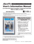
1
vF-
HomeCareProvider
SetupInstructions
REMstar'lPlus
Always use theseinstructions along with the (JserManual when
ussemblingor adjusting this equipment. For clinical systerns,
refer lo lhe setup gukle entitled Respironics Products in the
SleepInb (part#100975l)for equipment setup assistance.
MPORTANT !
CPAPSystem
This CPAP Systemis intended only for the
treatment ofadull Obstructive SleepApnea.
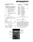
For devices with serial numbers greater than 2,000-000,the displa! screen has been upd.atedand an 8-pin
communications connector has been added.
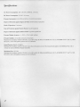
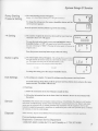
SystemContents
Ultra-fine
Filter
\t--l\\
,:Llz
Fr"''""
\-j
FilterGap
Fitters
Symbols DisplayScreen
FlexibleTubing
6 f t . ( 1 . 8 3m ) x 2 2 m m l . D .
Control Buttons
Etevation
O
Pressure
Start/ Stop
Z
RampStartPressure
-a
Ramp
lll
Humidifier
Setting
lll
Humidifier
on / off
,{
Y
|.
r-r ,
Hoursof Use
x
v
A
./ 3 \
N
:
Numberof nights
TherapySetupMenu
Settings
arebeingerased
ButtonLights
Attention,consult
accompanyingdocuments
AC Power
DCPower
t--'l
Lll
r >4 Hi'x,I;i:J:'..
f,
Device Label
tr
TypeBF AppliedPart
Classll (Doublelnsutated)
Equipment
lPXO Ordinary
-C,S
,f\
E::J
"@L
)
/hS
EuropeanCE Declaration
of Conformity
ttotirieoBodyApproval
for Standards
Compliance
Canadian/US
certification
ElectrostaticDischarge(ESD) Susceptibility
Specifi.cations
Hz, L0 A max.
AC PowerConsumption:100- 240VAC,5O16O
DC PowerConsumption:12VDC, 3.0A max.
PressureIncrements:4.0 to 20.0cm HrO (in 1.0cm HrO increments)
Degreeof ProtectionagainstIngressof Water: IPX0 OrdinaryEquipment
Mode of Operation:Continuous
Tlpe of ProtectionagainstElectric Shock:ClassII Equipment
Degreeof ProtectionagainstElectric Shock:TypeBFAppliedPart
PressureDisplayAccuracy:+l (0.15+ 47oof actualreading)
PressureStability:4.0 to 20.0cm HrO (tl.0 cm HrO)
with EN 17510@ 7, 13,& 20 cm HrO @ 500ml with BPM setto 10,15,& 20 BPM @ 23" C (+2oC), SOaVo
in accordance
Measured
pressure
of 101.54kPascals.
RH (t57o),andan atmospheric
SoundPressureLevel: <30 dB(A)
appliesto theREMstarPluswith or
with EN 17510@ 10cm HrO at thepatientcircuit.This measurement
in accordance
Measured
withoutthe optionalREMstarHeatedHumidifier.
Maximum Flow: 35 LPM
with EN 17510@ 7,13, & 20 cm HrO @ 500ml with BPM setto 10,15,& 20 BPM @ 23" C (+2"C),5OVo
in accordance
Measured
pressure
of 101.54kPascals.
RH (t57o),andan atmospheric
'W'arnings
(y Cautions
CAUTION!
' US federal law restricts this device to sale by or on the order of a physician.
Indicatesthe possibility of
damageto the device.
WARNING!
Indicatesthepossibility
for injury to the useror
operator.
. This device is intendedfor adult use only.
. This device is not intendedfor lift support.
. CPAPdeviceshave the potential to induce rebreathing of exhaled
air.
Tb reduce this potential, observethefollowing:
- Use Respironicscircuit accessories.
- Do not wear the mask and headgear
for more than afew minutes while the unit is
not operating.
- Do not block or try to seal the vent holes in the exhalation port.
As with most CPAPdevices,at low cPAp pressures,some exhaled gas(co") may remain
in the mask and be rebreathed.
' Do not use this device if the room temperatureis warmer than 95" (35"
F
C). If thk device is
used at room temperatureswarmer than 95oF (35" C), the temperatureof the airflow may
exceed106" F (41" c). This could cause irritation to the patientts airway.
'This equipment is not suitable
Jor use in the presenceof aflammable anestheticmixture with
air or with oxygen or nitrous oxide.
' If you notice any unexplainedchangesin the performance of this
device, if it is making
unusual or harsh sounds,ifit has been dropped or mishandled,or ifthe enclosureis broken,
discontinue use. Contact RespironicsCustomerService Department and replace any damaged
parts before continuing use.
'Tb avoid electrical shock, disconnectthe power cord before cleaning.
DO NOT immerse the
REMstar Plus in any fluids.
' Pins of connectors identified with the ESDwarning symbol should
not be touched.
Connectionsshould not be made to theseconnectorsunless ESDprecautionary procedures are
used. Precautionary proceduresinclude methodsto prevent build-up of electrostatic discharge
(e.g', air con'ditioning,humidification, conductivefloor coverings, and non-syntheticclothing),
discharging one's body to thelrame of the equipmentor systemor to earth or a large metal
object, and bonding oneselfby meansof a wrist strap to the equipmentor systemor to earth.
When assessingthe relativerisks and benefitsof using this equipment,the clinician shouldunderstand
Contraindications
that this device can deliver pressuresup to 20 cm HrO. In the event of certain fault conditions, a maximum pressureof 30 cm HrO is possible. Studieshave shown that the following pre-existingconditions
may contraindicatethe use of CPAP therapy for some patients:
. BullousLungDisease
. Pathologically t ow Blood Pressure
. Pneumothorax
' Pneumocephalushas been reported in a patient using nasal Continuous
Positive
Airway Pressure.Caution should be used when prescribing CPAP for susceptible
patients such as those with: cerebral spinal fluid (CSF; teaks,abnormalitiesof the
cribriform plate, prior history of head trauma, and/or pneumocephalus.(Chest 1989;
96:1425-1426)
The use of CPAP therapy may be temporarily contraindicatedif a patient exhibits signs of a sinus or
middle ear infection. Not for use with patientswhose upper airways are bypassed. Should your patient
have any of theseconditions, a physician will determine if CPAP therapy is appropriate.
3
Accessories
WARNING!
Do not connect any equipmentto the REMstar Plus unlessrecommendedby Respironicsor the doctor.
Verify that an exhalation port is present to exhaustCO, from the circuit. If circuit accessories,other than
those recommendedby Respironics,are connectedto the REMstar Plus, pressuresmust be verified. Use oJ
theseaccessoriesmay alter the pressurereceived,reducing
the effectiv eness of treatment.
RespironicsAccessories
alwaysfollow the instructions
When using accessories.
enclosedwith the accessories.
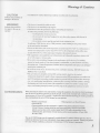
RecommendedPatientCircuit
,L Respironics nasal mask with integrated exhalation
port (or Respironicsmask with separateexhalation
port such as the Whisper Swivel@II)
2. Respironics6 ft. (1.83m) x22mm I.D. flexibletubing
3. Respironicsheadgear(notshown)
WARNING!
If this device is usedfor multiple persons (e.g.,rental devices)a low-resistance, mainflow bacterinfilter
should be insnlled in-line betweenthe device and the circuit tubing. Pressures must be verified when
slternate or optional accessoriesare in place.
DC Power
The Respironics DC Power Cord can be usedto operatethis device in a stationary
recreationalvehicle,boat,or motor home. The Respironics DC Battery Adapter
Cable (when usedwith the RespironicsDC Power Cord) enablesthe deviceto be
operatedfrom a 12 VDC free-standingbattery.
Humidifiers
The Respironics REMstar Heated Humidifier and Pass-over Humidifier are available for use with this device. The humidifiers may reduce
nasaldrynessand irritation by adding moisture(and heatif applicable)to
the airflow. When using other humidifiers, verify that the delivered
pressure is correct and that proper therapy is being delivered. DC
power cannot be used to operate the heated humidifier.
Oxygen
Oxygen may be addedat the mask connection. Pleasenote the wamings
listed below when using oxygen with this device.
4
WARNING!
The oxygen supply must comply with the local regulations for medical oxygen.
WARNING!
A Respironics Pressure Valve (Part number 302418) must be placed in-line with the patient circuit.
WARNING!
Turn this device on before turning the oxygen on, Turn the oxygen off before turning this device off.
This will prevent oxlgen accumul.s.tionin the device.
WARNING!
Oxygenacceleratesftres.Keepthisdeviceandtheoxygencontainerawayfromheatropenflames,any
oily substance,or other sourcev of ignition. DO NOT smoke in the area near this device or the oxygen
container.
WARNING!
When administering fixed-flow supplemental oxygen, the O, concentration ma! not be constant. The
inspired oxlgen concentrstion will vary depending on the CPAP settings, paticnt breathing pattern, and
the leak rate. Substantial leaks around the mask may reduce the inspired oxygen concentrution to less
than the expectedconcentrations. Appropriate patient monitoring should be implemented.
SysternSetup
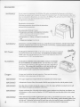
Filters
CAUTION!
Installthefilters.
Thepollenfilter mustbe in placeat all timeswhenthe
REMstar Plus is operating. The white ultra-finefilter is
optionaland can be usedin additionto thepollenfilter. The
peoplewho are sensitive
ultra-finefilter is recommendedfor
to tobaccosmokeor othersmallparticles.
white,
ultra-finefilter
1. Ifyou are usingthe ultra-finefilter,placeoneofthe
pollen filters over the ultra-fine filter.
pollenfilter
2. Insert the filter(s) into the filter area on the back ofthe
REMstar Plus.An extrafilteris includedfor thepatient's
convenience.
3. Attach the filter cap. Position the cap so that the small opening on the cap is facing down. Insert
the cap's tabs into the filter area opening.
CAUTION!
ControlPanel
Ifthis device has been exposedto either very hot or ver! cold temperatures, allow it to adjust to room
temperature before beginning the following setup procedures.
Display Screen: All devicesettingswill appearhere.
Pressure StarUStop Button: Use this button to turn start or
stop the airflow. DO NOT start the airflow until the circuit
tubing is connected.
Humidifier Button: Use this button when the optional
REMstar HeatedHumidifier has beenprescribed.This
button will turn the humidifier or/off and control the heat settine. Follow the instructionsincludedwith the humidifier.
Heated
Humidifier
Button
Ramp
Button
Ramp Button: Use this button to startthe ramp cycle (which lowers the airflow pressure).
+a
rv
@
lM PO RTANT!
Whenthe deviceis in the TherapySetupMenu, the humidiftcrand ramp buttons
operateas up and downkcysto changethe settings.Thepressurestartlstopbutton
wiII takeyou to the nextscreen.
IMPORTANT!
For deviceswith serialnumbersof 2,000,000and greater,thedisplayscreenhas beenupdatedand an
8-pin communicationsconnectorhas beenudded,Both displayscreensare shownbelow.
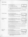
TherapySetup
Menu
Enter
1. Plug the prgnged end of the power cord into an electrical outlet. To enter the Therapy Setup
Menu, hold the ramp and pressure on/off buttons down while plugging the power cord into the
device.The airflow will automaticallystart,and the display screenwill show the currentelevationsetting
and the unlock symbol.
IMPORTANT!Prescribed therapy settings can be set only using the Therapy Setup Menu.
To prevent patients from
tampering with the settings, do not reveal the d.irections to access the Therapy Setup Menu.
5
SysternSetup
Elevation
Setting
a. The elevation setting will appear.
settingin thePatientSetupMenu.
Thepatient alsohas qccess
to this
Lo or 1 = lessthan2,500ft. (<762 m)
M or 2 =2,500to 5,000ft. (762m to 1524m)
Hi or 3 = 5,001ro 7,500ft. (1525m to 2286m)
,-{f,
H,
or{,, f
NOTE: Elevationsof 7,500ft. (2256 m) may affict the accuracyof the
pressure.Veify thepressuresettingswith a watercolumn
manometer.
I
To changethe setting,pressthe ramp or humidifier button until the correct settingappears.
Pressthe pressurestarUstopbutton to go to the next setting.
PressureSetting
b.The CPAPprressure
settingwill appear.
Range: 4 to 20 cm HrO (in I cm HrO increments)
To changethe setting,pressthe ramp or humidifier button untit
the correct pressureappears.
Pressthe pressurestarUstopbutton to go to the next setting.
FineAdjustment
Setting
c. The CPAPfine adjustmentsettingwill appear.This setting
allowsyou to calibratethedevicesothatthepressure
settingcanbe
verifiedwith a manometer,
Range:> -1.5to L5 cm H.O (in
approximately0.1cm HrO increments)
Ifyou do not want to calibrate the device,pressand releasethe
pressurestart/stopbutton to go to the next setting.
If you do want to calibratethe device,follow the directionsbelow:
ie
f,
cm
Ha0
f
'i$
!a
ie
f,
fl cm
.U HEO
f
ie i.0'i$
1. Connectthe patientcircuit to the REMstar Plus. Make surethereis an exhalationleak in
the
circuit.
2. Zero the manometer,and connect the manometerat the patient mask. Make sure the pressure
has
stabilizedfor at least60 seconds.
3' If the pressuresetting is not the sameas the manometerreading, pressand releasethe ramp
or
humidifier button to changethe setting.
Press the pressure starUstop button to go to the next setting.
RampTime
Setting
d.The ramp time will appear.
Range: 0 to 45 minutes (in 5 minute increments) Thepatientatso has
accessto this settingin the Patient SetupMenu,
i5
To changethe setting,pressthe ramp or humidifier button.
Pressthe pressurestarUstopbutton to go to the next setting.
6
NOTE: If the ramp time is setta ,,0" minutes,or if the CpAppressure
setting is 4 cm Hr0, thefollowing ramp setting will not be
displayed. Go to Stepf.
f.l
f-a
[:c-[
System Setup (r Seruice
RampStarting
PressureSetting
e. The ramp starting pressurewill appear.
Range: 4 to PrescriptionSetting(in I cm HrO increments)
To changethe setting,pressthe ramp or humidifier button until the
correct pnessureappears.
f,:l
5
'i$
0z
rcm
Pressthe pressurestarUstopbutton to go to the next setting.
>4 Setting
The number of nights this devicehas beenusedfor more than four
consecutivehours (>4) will appear.
To erase the total and go back to zero, press and hold the ramp or
humidifier button. An "X" will appearin the lower left cornerand
the total will changeto "0000." (Pressingthe button again will restorethe
original count.)
Press the pressure starUstop button to go to the next setting.
ButtonLights
g. The button lights setting will appear. This setting allows you to have
the lights behind the buttonstumed on or off while the airflow is turned
on. ([he lights will always be on when the airflow is off.)
The patient also has accessto this setting in the Patient SetupMenu.
l=on
f,
xl>4
finnn
UUUU
I>4
f,
n
Ll
x
f,
LEd
0=off
To changethe setting,pressthe ramp or humidifier button.
ExitSettings
-]| HzO
v
I
I
f,
n
IJ
h. The settings are complete. To repeat the settings, press the pressure starflstop button.
To exit the Therapy Setup Menu, hold the pressure starUstop button down and press the ramp
button one time. The airflow will turn off.
2. Final Steps
a. Follow the instructions in the User Manual to install the filter.
b. Fill out the information form in the front of the User Manual. Review the User Manual with
the patient.
Service
The REMstar Plus Systemdoesnot requireroutineservicing. If the REMstar Plus beginsto mal function,
refer to the "Troubleshooting" section of the User Manual or contact Respironics,Inc. Repairs and adjustments must be performed only by trained personnelfully acquaintedwith this equipment. Service performed by unqualified personnelor installation of unauthorizedparts could causepersonal injury, invalidate
the warranty, or result in costly damage.
Disposal
When necessary,
disposeof the REMstar Plus and accessories
in accordancewith local regulations.
Ifyou need product assistance,call
Respironics
CustomerServiceDepartment
-6443(withinhe U.S.andcanada)or r-724-387-4000
1-800-345
7
EMC Inforrnation
Gurnmcn ANDMANUFACTURERTs
Drccr,lrurroN - ELEcTRoMAGNETTc
EMrssroNs
This deviceis intended
for usein theelectromagnetic
environment
specified
below.Theuserof thisdeviceshouldmakesureit is used
in suchan environment.
EprrsslorvsTBsr
Coprpulxce
Elncrnou^l,cxnrlc ExvrnoNMENTGurol,xcn
RF emissions
CISPR1I
GroupI
This deviceusesRF eneigyonly for
its internalfunction.Therefore,its
RF emissionsarevery low andare
not likely to causeany interference
in
nearbyelectronicequipment.
RF emissions
CISPR II
ClassB
Harmonic emissions
IEC 61000-3-2
ClassA
Thisdeviceis suitablefor usein all
establishments,
includingdomestic
establishments
andthosedirectly
connected
to the publiclow-voltage
powersupplynetwork.
Voltagefluctuations/
Flickeremissions
rEC61000-3-3
Complies
r
I
t
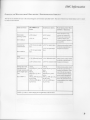
EMC Information
i
GurnlNcn
AND MANUFACTuRERts Dncr,lnrrroN
- ELECTRoMAGNETTc luruuNrry
This device is intendedfor use in the electromagneticenvironmentspecifiedbelow.The userof this device should make sure it is used
in suchan environment.
hrpruxrry Tnsr
IEC 60601Tnsr
Lnvnl
Coruprrlxcp LrvBr,
llectrostatic
)ischarge(ESD)
t6 kV contact
t6 kV contact
+8 kV air
t8 kV air
:EC 61000-4-2
Electrical fast
Iransient/burst
+2 kV for power supply +2 kV for supplymains
lines
IEC 61000-4-4
+1 kV forinput-output
lines
*l kV for inpuVoutput
lines
Er-Bcrnorr.rlcnnrlcEnvr- Gurolxcn
RoNMENT
Floors should be wood,
concreteor ceramic tile.
If floors are coveredwith
syntheticmaterial, the
relative humidity should be
atleasL30Vo.
Mains power quality shoulc
be that of a typical home or
hospital environment.
)urge
rEC61000-4-5
Voltagedips, short
intenuptions and
vollage variations on
power supply input
lines
rEC 61000-4-11
+l kV differential mode +1 kV differential mode
t2 kV common mode
Mains power quality should
be that of a typical home or
+2 kV for common modt hospital environment.
<5VoU,
(>95Vodip in Ur) for 0.5
cycle
407o U,
(6OVodip in Ur) for 5
cycles
10VoU, (30Vodip in Ur)
for 25 cycles
<5VoUr(>957o dipin
Ur) for 5 sec
4Vo U,
(>957o dip in Ur) for 0.5
cycle
40Vo U,
(6OVodip in Ur) for 5
cycles
70VoU, (307odip in Ur)
for 25 cycles
4Vo Ur(>95Vod\p in
L/r) for 5 sec
Mains power quality should
be that of a typical home or
hospital environment.If the
user of the device requires
continuedoperation during
power mains interruptions,
it is recommendedthat the
device be poweredfrom an
unintemrptible power supply
or a battery.
NOTE: U, is the a.c. mains voltage prior to applicationof the test level.
9
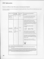
EMC Inforrnation
Gurnlxcr
Dncr.lnrrroN
ANDMANUFACTURER'S
- ELECTRoMAGNETTc
lvruur.nrv
This deviceis intended
for usein theelectromagnetic
environment
specified
belowThe userof thisdeviceshouldmakesureit is used
in suchan environment.
Iuuuxnv Tnsr rEC 60601
Tnsr LnvBl
Powerfrequency
(50/60Hz)
magneticfield
3A/m
Coupr,rlxcn
Lnvnl
3A/m
Er.Bcrnoulcrnrrc ExvrnoNMENTGum,lxcB
Power frequency magneticfields should be at
levels characteristicof a typical location in a
typical home or hospital environment.
IEC 61000-4-8
Portableand mobile RF communications
equipmentshould be usedno closer to any
part of the device, including cables,than the
recommendedseparationdistancecalculatedfrom
the equation applicable to the frequency of the
transmitter.
Recommended separation distance
ConductedRF
rEC61000-4-6
RadiatedRF
rEC61000-4-3
d= l.2rlF
3 Vrms
150kHz to 80
MHz
3 Vrms
3 V/m
80 MHz to 2.5
GHz
3 V/m
a= t.AE
d = 2.\P
8oMHztoSooMHz
800MHzto 2.5GHz
where P is the maximum output power rating
of the transmitterin watts (W) according
to the transmitter manufacturer and d is the
recommendedseparationdistancein meters(m).
Field strengthsfrom fixed RF transmitters,as
determinedby an electromagneticsite survey,"
should be less than the compliancelevel in each
frequencyrange.b
Interferencemay occur in the vicinity of
equipmentmarked with the following symbol:
(r.)
\Y
{OTE 1 At 80 MHz and 800 MHz, the higher frequency range applie
{OTE 2 There guideline my not apply in all situations. Eectrcmagnetic prcpagation is affected by absorption and refletion
rtructures, obj€ts, and pople.
fron
a
Field strengths from fixed tmsmitters, such s brc stations for radio (cellular/cordless) telephones md lmd mobile radios,
mateur radio, AM and FM radio brcadmt md TV brmd€st cmnot be predicted theorctically with a€urcy. To uress the electromagnetic
)nviroment due to fixed RF trmsmitters, m el@tromagnetic site survey should be considered. If the mruued field strength in the location
n which the device is used exceeds the applicable RF compliance level above, the devie should be obrcrved to verify normal opemtion. If
rbnomal perfomne
is obsrued, additional mmures may be necessary,such as re-orienting or relocating the device.
b
Over the frequency roge 150 kHz !o 80 MHz, the field strengths should be less than 3 V/m.
10
EMC Inforrnation
RncolrunNDED SEPARATION
DIsTANCEsBETwEENPoRTABLEANDMoBTLB RF CoulruNrcATroNs EqurrvrnNr lNn
TnrsDnvrcn
This device is intendedfor use in an electromagneticenvironmentin which radiatedRF disturbancesare controlled.The customeror
the userof this device can help preventelectromagneticinterferenceby maintaininga minimum distancebetweenportableand mobile
RF communicationsequipment(transmitters)and this deviceas recommendedbelow,accordingto the maximum output power of the
communicationsequipment.
Rrrno Mlxllruvr
Pownn Ourpur or
Tn.lnsurrrnn
w
Snplnluox Drsuxcn Acconllnc ro FnneuBxcy or Tnrurslnrrpn
M
150kHz to 80 MHz
d= 1.2..1F
80 MHz to 800 MHz
d= 1.2rlF
800 MHz to2.5 GHz
d= 2JrJp
0.01
0.12
0.12
0.23
0.1
0.38
0.38
0;73
I
t.2
t.z
2.5
l0
3.8
3.8
7.3
r00
t2
t2
z5
For transmittersrated at a maximum output power not listed above,the recommendedseparationdistanced
in meters(m) can be estimatedusing the equationapplicableto the frequency of the transmitter,where P is
the maximum output power rating of the transmitterin watts (W) according to the transmittermanufacturer.
Note 1: At 80 MHz and 800 MHz, the separationdistancefor the higher frequency range applies.
Note 2: These guidelinesmay not apply in all situations.Electromagneticpropagationis affectedby
absorptionand reflection from structures,objects,and people.
II
RESptRONtcs'RESPIRONIG". .
Deutschland
I
F
1001 MurryRidgeLane
Murrysville,Pennsylvania
15668-8550 USA
\
\
Gewerbestrasse1?
82211 HerschingGermany 0123
1027796
JW 07/06/05