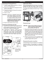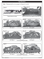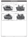
1
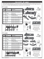
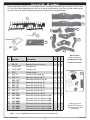
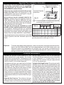
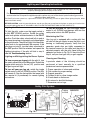
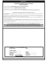
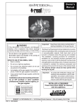
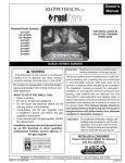
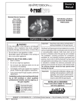
Instructions
Models:
MPEC-2-24-10(M)(P)
MPEC-2-30-10(M)(P)
MPEC-2-36-10(M)(P)
MPEC-2-48-10(M)(P)
MPEC-2-60-10(M)(P)
With Safety
Pilot System
and remote
control
EPIC BURNER SEE-THRU GAS LOG SET
IMPORTANT: READ THESE INSTRUCTIONS
WARNING
CAREFULLY BEFORE STARTING
INSTALLATION OF YOUR LOG SET
If the information in this manual is not followed
exactly, a fire or explosion may result, causing
property damage, personal injury, or loss of life.
The Peterson Real-Fyre® gas log set is to be installed
only in a solid-fuel burning fireplace with a working
flue constructed of noncombustible material. Solidfuels shall not be burned in a fireplace where this
gas log set is installed. The installation, including
provisions for combustion, ventilation air, and
required minimum permanent vent opening, must
conform with the National Fuel Gas Code (ANSI
Z223.1/NFPA 54) and applicable local building
codes. In Canada, the installation must conform with
the Natural Gas and Propane Storage and Handling
Installation Code (CSA-B149.1). A damper clamp
is included to maintain the minimum permanent
vent opening and to prevent full closure of the
damper blade. The chimney damper should be
fully opened when burning the log set. The log
set is designed to burn with yellow flames; thus
adequate ventilation is absolutely necessary.
Do not store or use gasoline or other flammable
vapors and liquids in the vicinity of this or any
other appliance.
WHAT TO DO IF YOU SMELL GAS:
• Open a window.
• Do not try to light any appliance.
• Do not touch any electrical switch; do not
use any phone in the building.
• Immediately call the gas supplier from
a neighbor’s phone and follow the gas
supplier’s instructions.
• If you cannot reach the gas supplier, call the
fire department.
Installation and service must be performed
by an NFI Certified or other qualified
professional installer, service agency, or
the gas supplier.
We recommend that our gas
hearth products be installed
and serviced by professionals
who are certified in the U.S.
by the National Fireplace
Institute® (NFI) as NFI Gas
Specialists.
INSTALLER & CONSUMER:
These instructions MUST be retained
with this appliance.
Important:
For safe operation and proper performance of this product and to comply with certification,
listings, and building code acceptances, use ONLY Peterson Real-Fyre® controls, parts,
and accessories that have been specifically listed or certified for use with this burner
system. Use of other controls, parts, or accessories is prohibited and will void all warranties,
certifications, listings, and building code approvals, and may cause property damage,
personal injury, and loss of life.
ROBERT H. PETERSON CO. • 14724 East Proctor Avenue, City of Industry, CA 91746
REV 3 - 0906081646
1
L-A2-25109
Table of Contents
SUBJECT
PAGE
Parts List (24" - 30" models)
Parts List (36" - 60" models)
Fireplace Requirements
Minimum Free Opening Area of Chimney Damper
Installing the Damper Clamp
Installation
Installing and Testing the Burner
Checking and Adjusting the Pilot
Adjusting Air Mixers
Placing the Logs
Placing the Decorative Lava Rock
Log Placement
Log Placement (cont.)
Lighting and Operating Instructions
Lighting the Pilot
Maintaining the Pilot
Safety Pilot System
Maintenance and Service
Maintenance
Service
Flame Appearance
Troubleshooting
Warranty
REV 3 - 0906081646
2
3
4
5
6
6
7
7
7
7
7
7
8
9
10
10
10
10
11
11
11
11
11
12
L-A2-25109
Parts List (24" - 30" models)
Before beginning installation, be sure the gas log set is complete by comparing its contents with this Parts
List. Parts may differ depending upon the size of the set purchased. Be sure you know the model number and
size of your set when ordering replacement or optional parts and accessories.
24" models
Item
No.
4
Part No.
7
Description
1.
EC-2-24-10(M)(P) Valve, Pilot, Burner assembly
2.
RR-1A
Remote kit (not in ‘M’ units)
3.
CK-5-24SP
Connector kit
4.
DC-1
Damper clamp
5.
OCC-10
Lava Rock (qty of 3)
8
11
6
3
6.
MPL-24BF
Mammoth Pine front bottom log 24"
7.
MPL-24BF
Mammoth Pine front bottom log 24"
8.
MPL-15T
Mammoth Pine top log 15"
9.
MPL-20T
Mammoth Pine top log 20"
10.
MPL-17T
Mammoth Pine top log 17"
11.
BL-13T
Mammoth Pine top log 13"
9
10
5
2
Photos not to scale.
Contact your local
Real-Fyre® dealer for
replacement parts and
accessories.
1
30" models
Item
No.
6
Part No.
4
Description
1.
EC-2-30-10(M)(P) Valve, Pilot, Burner assembly
2.
RR-1A
Remote kit (not in ‘M’ units)
3.
CK-5-24SP
Connector kit
4.
DC-1
Damper clamp
5.
OCC-10
Lava Rock (qty of 4)
6.
MPL-30BF
Mammoth Pine front bottom log 30"
7.
MPL-30BF
Mammoth Pine front bottom log 30"
8.
MPL-18T
Mammoth Pine top log 18"
9.
MPL-18TY
Mammoth Pine top log 18"
10.
MPL-20T
Mammoth Pine top log 20"
11.
MPL-17T
Mammoth Pine top log 17"
7
9
8
3
10
11
2
5
Photos not to scale.
Contact your local
Real-Fyre® dealer for
replacement parts and
accessories.
1
REV 3 - 0906081646
3
L-A2-25109
Parts List (36" - 60" models)
Before beginning installation, be sure the gas log set is complete by comparing its contents with this Parts
List. Parts may differ depending upon the size of the set purchased. Be sure you know the model number
and size of your set when ordering replacement or optional parts and accessories.
14
1
13
8
7
4
10
12
6
3
9
5
11
MP-60 shown.
Item
No.
1.
2.
3.
or
4.
5.
6.
7.
8.
9.
10.
11.
12.
13.
or
or
14.
or
or
Part No.
EC-2-60-10M(P)
RR-1A
CK-5-24SP
CK-5-18SP
DC-1
Description
Valve, Pilot, Burner assembly
Remote kit (not in ‘M’ units)
Connector kit
Connector Kit
Damper clamp
OCC-10
Lava Rock (see right for qty)
MPL-17T
MPL-18TY
MPL-18T
MPL-19T
MPL-20T
MPL-21T
MPL-24T
MPL-36BF
MPL-48BF
MPL-60BF
MPL-36BF
MPL-48BF
MPL-60BF
Mammoth Pine top log 17"
Note:
Mammoth Pine top ‘Y’ log 18"
Mammoth Pine top log 18"
Mammoth Pine top log 19"
Mammoth Pine top log 20"
Mammoth Pine top log 21"
Mammoth Pine top log 24"
Mammoth Pine front bottom log 36"
Mammoth Pine front bottom log 48"
Mammoth Pine front bottom log 60"
Mammoth Pine front bottom log 36"
Mammoth Pine front bottom log 48"
Mammoth Pine front bottom log 60"
60 48 36
x x x
x x x
x x
x
x x x
6 5 4
x x x
x x x
x x
x x
x x
x
x
x x x
x
x
x
x
x
x
Logs 8-11 are not
included with all sets.
Photos not to scale.
2
Contact your local
Real-Fyre® dealer for
replacement parts and
accessories.
Values in bold Italics change with burner size and model log set.
REV 3 - 0906081646
4
L-A2-25109
Important Pre-installation Information
Check to be sure the fireplace meets venting and
construction requirements for the installation
of the Real-Fyre® gas log set (see FIREPLACE
REQUIREMENTS section, below).
Minimum clearances to
sidewalls and ceiling
min. 42"
Standard Fireplace
dimensions
This burner may only be connected to the gas type
listed on the label. Never use propane gas in a log
set designed for natural gas or natural gas in a log set
designed for use with propane gas.
min.
6"
Rear
opening
Height
Be sure the gas log set is properly sized for the
fireplace. Improper sizing may negatively impact the
proper drafting of the fireplace. Additionally, too large
a log set will adversely affect the burn and hamper the
proper operation of the control system. Fig. 5-1 illustrates
the critical dimensions of the firebox.
Depth Front
Front
opening
Fig. 5-1
Note:
It is recommended that complete firebox dimensions
be obtained to ensure proper sizing.
Min. Fireplace Size
Model no.
This gas log set must be installed by an NFI
Certified or other qualified professional installer.
The installation, including provisions for combustion
and ventilation air, must conform with local codes, or, in
the absence of local codes, with the latest edition of the
National Fuel Gas Code, ANSI Z223-1, and NFPA54.
MPEC-2-24-10
MPEC-2-30-10
MPEC-2-36-10
MPEC-2-48-10
MPEC-2-60-10
BTU*
Width
Depth
Height
(x 1000)
34"
40"
48"
60"
72"
24"
24"
30"
30"
30"
26"
30"
36"
36"
36"
90
110
190
215
260
Orifice drill size
(top/front)
Nat.
LP
28/48 47/56
19/41 40/55
13/33 36/47
2/29 30/42
none 22/29
Keep the appliance area clear and free from combustible
materials, gasoline, and other flammable vapors and *Nominal BTU based on gas inlet pressure. Nominal
gas inlet pressure for natural gas is 5" W.C..
liquids.
Important:
To comply with building code acceptances, and for safe operation and proper performance of this
log set, use ONLY Peterson Real-Fyre® parts and accessories. Use of other controls, parts, and
accessories which are not designed for use with Real-Fyre® gas log sets is prohibited and will
void all warranties, certifications, listings, and building code approvals, and may cause property
damage, personal injury, or loss of life.
Fireplace Requirements
The Real-Fyre® gas log is to be installed only in a fully
vented, fireplace with an open damper. The chimney
must be free of any obstructions. The fireplace must be
designed and approved to burn wood. The fireplace flue
must be at least 8" at its smallest dimension.
inlet gas supply pressure is 10.5" w.c. for natural gas.
The minimum inlet gas supply pressure for the purpose
of input adjustment is 11" of water column (w.c.) for
propane gas. The maximum inlet gas supply pressure
is 13" w.c. for propane gas.
The fireplace must have a gas supply line that has been
installed by a qualified technician in accordance with all
local codes. The gas supply line must be ½" minimum
interior diameter. If the gas line to the fireplace is longer
than 5', a larger diameter line may be necessary.
Testing the Gas Supply System: The gas log set and its
individual shut-off valve must be disconnected from the
gas supply piping system while performing any tests of the
piping system at pressures in excess of ½ psig. The gas
log set must be isolated from the gas supply piping system
by closing its individual manual shut-off valve during any
pressure testing of the gas supply piping system at test
pressures equal to or less than ½ psig.This is accomplished
by closing the gas supply line valve required by NFPA 54.
A fireplace screen must be in place when the appliance
is in operation and, unless other provisions are provided,
the screen shall have an opening(s) for introduction of
combustion air. When glass fireplace doors are used,
operate the gas log set with the doors open.
Be sure to clean the fireplace floor of any ashes or other
foreign materials. It is recommended that the fireplace
and chimney be inspected by a chimney sweep or other
qualified person before you install the Real-Fyre® gas
log set.
Required Gas Pressure: The minimum inlet gas
supply pressure for the purpose of input adjustment is
5" of water column (w.c.) for natural gas. The maximum
REV 3 - 0906081646
5
L-A2-25109
Minimum Free Opening Area of Chimney Damper
Minimum Free Opening Area of Chimney Damper for Venting
For Factory Built Fireplaces
Log Set Sizes
For Masonry Built Fireplaces
Log Set Sizes
Chimney
Height
24"
30"
36"
48"
15'
20'
25'
30'
57 sq. in.
51 sq. in.
48 sq. in.
45 sq. in.
63 sq. in.
57 sq. in.
54 sq. in.
51 sq. in.
119 sq. in.
107 sq. in.
102 sq. in.
96 sq. in.
135 sq. in.
121 sq. in.
115 sq. in.
108 sq. in.
60"
24"
30"
36"
48"
60"
163 sq. in. 61 sq. in. 67 sq. in. 123 sq. in. 139 sq. in. 167 sq. in.
147 sq. in. 55 sq. in. 61 sq. in. 111 sq. in. 125 sq. in. 151 sq. in.
139 sq. in.
131 sq. in. 49 sq. in. 55 sq. in. 100 sq. in. 112 sq. in. 135 sq. in.
Note: The minimum chimney height from hearth to top of chimney is 15'.
Installing the Damper Clamp
4. Should the damper clamp not fit, install a
permanent damper stop or provide some other
means of preventing full and/or accidental
closure of the damper such as removing the
damper blade.
A damper clamp (See Parts List) is provided as a
means to prevent full and/or accidental closure of
the fireplace damper when installed as illustrated
(Fig. 6-2). When the gas log set is operating,
the damper must be fully open. To install the
damper clamp:
1. Open the fireplace damper.
2. Place the damper clamp (Fig. 6-1) over the
damper blade as in Fig. 6-2.
3. Tighten the set screw of the damper clamp
with pliers or a wrench so that it affixes to the
damper blade. The clamp must be permanently
installed.
Open
Damper clamp
Fig. 6-1
REV 3 - 0906081646
Closed
Fig. 6-2
6
L-A2-25109
Installation
Installing and Testing the Burner
Adjusting Air Mixers
1. Connect the gas flexible connector to the gas
stub from the fireplace wall.
Burners are equipped with air mixers for the upper
(except 60") and front burners. Adjust the size
and color of the flame by opening (turn outward)
or closing (turn inward) as shown in Fig. 7-3 and
Fig. 7-4.
2. Place the assembled burner and grate into the
center of the firebox.
3. Connect the other end of the gas flex connector
to the burner valve.
4. Check for leaks.
Open
CAUTION: CHECK ALL CONNECTIONS FOR
GAS LEAKS USING A HALF-ANDHALF SOAPY WATER SOLUTION.
IF A LEAK IS DETECTED TIGHTEN
CONNECTIONS AND TEST AGAIN.
NEVER USE AN OPEN FLAME TO
CHECK FOR GAS LEAKS.
Fig. 7-3
5. Place the heat shield over the valve.
Fig. 7-4
Placing the Logs
Checking and Adjusting the Pilot
CAUTION: Logs are heavy! Safely moving the
front or back logs requires two or
more people (see Fig. 8-2)
1. The pilot flame should encircle the generator tip
which is preset at the factory (Fig. 7-2). Ordinarily,
the pilot will not require field adjustment.
1. Place the front log on the grate in front of the
burner pipe with the flat down and the heat
chambers toward the burner pipe and the log
as far forward as possible while keeping the
back parallel with the burner pipe (Fig 8-2).
Repeat for the second front log on the opposite
side of the see-thru burner.
2. If adjustment is necessary, remove the cap
screw (Fig. 7-1) and turn the smaller gas
adjustment screw inside counterclockwise
to increase the pilot flame and clockwise to
decrease the pilot flame. Replace cap screw.
2. Place top logs across the front and back logs
in the order and positions shown for your
particular log set size on p. 8-9.
24" model
PILOT CAP
SCREW
IN
TH TH
TP
TP
Placing the Decorative Lava Rock
Locate the bag of lava rock and pour its contents
around the base of the grating in an attractive
pattern. Do not place the Lava Rock on the logs
or grate.
30" - 60" models
Fig. 7-2
Note: P i l o t f l a m e
should encircle
top of the
generator.
Fig. 7-1
REV 3 - 0906081646
7
L-A2-25109
Log Placement
Note: Reference the Parts List on page 4 for Figures 8-1 thru 8-8.
Fig. 8-2
Fig. 8-1
14
Place the burner system
Fig. 8-3
Place front bottom logs (requires at least two to lift)
Fig. 8-4
11
9
7
10
8
12
6
60" setup A
60" setup B
Fig. 8-6
Fig. 8-5
11
10
7
8
9
6
48" setup B
48" setup A
Fig. 8-8
Fig. 8-7
7
10
6
36" setup B
36" setup A
REV 3 - 0906081646
12
8
L-A2-25109
Log Placement (cont.)
Note: Reference the Parts List on page 5 for Figures 9-1 thru 9-4.
Fig. 9-2
Fig. 9-1
11
8
9
10
30" setup B
30" setup A
Fig. 9-4
Fig. 9-3
10
9
8
24" setup B
24" setup A
REV 3 - 0906081646
11
9
L-A2-25109
Lighting and Operating Instructions
FOR YOUR SAFETY, READ BEFORE LIGHTING
WARNING: If you do not follow these instructions exactly, a fire or explosion may result causing
property damage, personal injury or loss of life.
Do not use this appliance if any part has been underwater. Immediately call for a qualified professional
service technician to inspect the appliance and to replace any part of the control system and any gas control
which has been under water.
The Real-Fyre burner system has a pilot which can be lit by hand using a match or lighter. When lighting the pilot, follow
these instructions exactly.
BEFORE LIGHTING, smell all around the burner area for gas. Be sure to smell next to the floor as some gas is heavier than
air and will settle on the floor. IF YOU SMELL GAS, FOLLOW THE INSTRUCTIONS ON THE COVER (P. 1).
Lighting the Pilot
To light the pilot, make sure the toggle switch is
in the OFF (DOWN) position. Rotate the safety
valve knob pointer counterclockwise to the PILOT
position. Push the safety valve knob fully in and at
the same time place a long match or a butane lighter
at the pilot burner. The pilot will light. Hold the safety
valve knob in for approximately 60 seconds. If the
pilot does not stay lit, turn the safety valve knob to
the OFF position. Wait five minutes and repeat the
lighting instructions. If the pilot still fails to stay lit
see the Troubleshooting section.
Lighting and Extinguishing the Burner System
To turn on your gas log set with the pilot lit, turn
the safety valve knob to the ON position. Switch the
toggle switch control to the on (UP) position and
the gas log set will light.
To turn off your gas log set, switch the toggle
switch control to the off (DOWN) position. The pilot
will remain lit. See the instructions that came with
the remote kit (if purchased) for remote lighting
instructions.
To turn off the pilot, be sure the toggle switch
control is off (DOWN) and depress and turn the
safety valve knob to the OFF position.
Maintaining the Pilot
Your log set is equipped with a safety pilot that
will shut off the gas supply in case the pilot is not
burning or functioning properly. Verify that the
generator spade clips are tightly connected to
the terminal screws on the valve and the pilot is
adjusted properly with the pilot flame hitting the
generator as shown in Fig. 10-2 If the pilot will not
stay lit, call your local gas utility or gas supplier.
Cleaning and Checking
A periodic check of the following should be
performed at least annually by a qualified
professional service representative.
1. Proper operation of valves and switches.
2. Flue system for proper venting.
3. Damper operation
4. Orifices for dirt or other foreign matter.
5. Visual check on the burner.
6. Air mixers for dust/lint blockage.
7. Excessive soot on logs.
Safety Pilot System
24" models
TOGGLE
SWITCH
30" - 60" models
PILOT
BURNER
WIRING
HARNESS
JUMPER
WIRE
Lighting
the Pilot
PILOT
GENERATOR
PILOT
GAS PORT
PILOT CAP
SCREW
TH TH
TP
TP
IN
PILOT
GAS SUPPLY
SAFETY
VALVE
CONTROL
KNOB
Fig. 10-1
Fig. 10-2
Note: Pilot flame should encircle top of the generator.
REV 3 - 0906081646
10
L-A2-25109
Maintenance and Service
Maintenance
distribution or flame at air-mixer (if equipped).
Reference SOLUTION, to symptoms 2-4, of
Troubleshooting.
Once installed and operating properly, the RealFyre® gas log set requires very little maintenance.
You should inspect the log set and control annually Service
for the following:
It is recommended that a qualified professional
1. Excessive Sooting - Some sooting of service technician be called to service the
the log set is normal and adds to the gas log set and control should service be
natural appearance of burned wood. If soot required. The Troubleshooting section of these
accumulates, you may brush the soot off with instructions serves as a guide for ensuring
a stiff brush. Logs may also be cleaned by optimum performance of the gas log set.
allowing them to heat up, then spraying them
Flame Appearance
with water where soot has accumulated.
2. Debris around the control - Inspect the The flames should be blue at the base and a
control and pilot to be sure it is free of any combination of blue/yellow at the body and tips.
dirt or debris.
3. Insects and burner blockage - Check the
burner ports and the air-mixer, if present, to
make sure they are free from debris. Blocked
burner ports and orifices may result in poor flame
Troubleshooting
PROBLEM
CAUSE
SOLUTION
1. Pilot will not stay a. Pilot generator may not be producing
lit
sufficient millivoltage.
2. Pilot Burning.
No Gas to
Burner
3. Log set Not
burning properly
a. Check with a millivolt meter. Should be 250
millivolts or more.
b. Pilot flame making a blowing sound
b. Pilot needs adjusting (See Pilot Adjustment).
c. Generator wire leads attached to the
wrong terminals on the valve.
c. Connect leads per wiring diagram, previous
page
d. Defective thermomagnet safety in valve.
d. Replace valve.
a. Safety valve not turned to the ON
position after lighting pilot.
a. Turn to ON position.
b. Wire leads are not properly connected to b. Attach all wire leads tightly to proper terminals
valve or switch terminals
(See wiring diagram, previous page).
c. Voltage to pilot generator too low
c. See section 1a above.
d. Defective valve.
d. Replace valve.
a. Low flame/uneven flame.
a. Check for low gas pressure; minimum
operating pressures of 5" W.C. at manifold.
4. Log set will not a. Toggle Switch Control lead wires to the
shut OFF
valve may be shorted together or on
wrong terminals.
a. See wiring diagram, previous page. System
takes 15-20 seconds to complete shutdown
(nominal).
5. Frequent pilot a. Pilot flame is out of adjustment.
outage
b. Down drafts from the chimney,
extinguishing the pilot.
a. See section 1b above.
6. Log set shuts
down during
operation
a. Glass doors closed causing excessive
heat buildup.
a. Open glass doors.
b. Pilot generator improperly mounted on
rear of burner pans.
b. See (Mounting Pilot Assembly to Real-Fyre®
burners).
c. Heat shield not in place.
c. Place heat shield over valve.
7. Excessive soot a. Yellow flame impingement
on logs
REV 3 - 0906081646
b. Check draft. Consult with a qualified chimney
expert.
b. Open air shutter on front burner or main
burner as needed.
11
L-A2-25109
WARRANTY
PETERSON VENTED GAS LOG SETS
LIMITED WARRANTY
All Peterson gas logs are WARRANTED for as long as you own them (lifetime).
All Peterson burner assemblies are WARRANTED for TEN (10) YEARS.
SPK-26 controls are covered by a THREE (3) YEAR “All Parts” Warranty.
All other Peterson valves, pilots, and controls are covered by a ONE (1) YEAR Limited Warranty (excluding batteries).
PLEASE KEEP A COPY OF YOUR SALES SLIP FOR PROOF OF PURCHASE
This warranty applies to the original purchaser and to single family residential use only. It commences from date of purchase, and is valid only with
proof of purchase.
This warranty does not cover parts becoming defective through misuse, accidental damage, electrical damage, improper handling, storage, and/or
installation. Product must be installed (and gas must be connected) as specified in the instructions or operator’s manual, by a qualified professional
installer. Accessories, parts, valves, remotes, etc., when used must be Peterson Co. product.
This warranty does not apply to rust, corrosion, oxidation, or discoloration, unless the affected component becomes inoperable. It does not cover
labor or labor-related charges.
This warranty specifically excludes liability for indirect, incidental, or consequential damages. Some states do not allow the exclusion or limitation of
incidental or consequential damages, so the above exclusion may not apply to you. This warranty gives you specified legal rights, and you may have
other rights that may vary from state to state.
For additional information regarding this warranty, or to place a warranty claim, contact the R.H. Peterson dealer where the product was purchased.
TO REGISTER YOUR PRODUCT ONLINE GO TO: WWW.RHPETERSON.COM,
AND CLICK ON PRODUCT REGISTRATION. THANK YOU FOR YOUR PURCHASE.
ROBERT H. PETERSON CO.
Quality Check
Date:___________
Orifice # (Main):__________
Orifice # (Other):__________
Leak Test:
___________
Burn Test:
___________
Gas Type:
NAT. / PROPANE
Model #:
___________
Serial #:
___________
Air Shutter: ___________
Inspector: ___________
Robert H. Peterson Co. • 14724 East Proctor Avenue • City of Industry, CA 91746
12