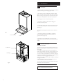
1
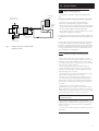
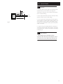
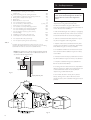
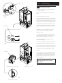
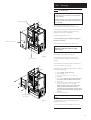
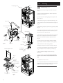
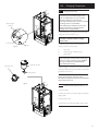
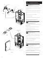
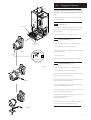
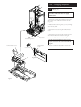
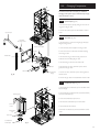
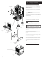
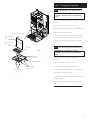
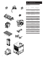
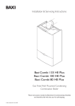
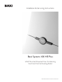
8.0 Installation
8.7
Making The Electrical Connections
WARNING: This appliance must be earthed
1. The electrical connection is on the rear left hand side
of the unit (Fig 33).
N
L
2. Remove the electrical plug from the hardware pack.
3. Connect S/L, N & E into the plug and connect it to the
socket at the back left at the bottom of the boiler.
Metal Shield
Plug
4. Remove the metal shield from the hardware pack and
connect it over the plug.
Filter
5. The boiler is factory set to give a maximum output of
22.0 kW (75,000 Btu/hr). The Control PCB jumper
positions are as follows:
CN11 (Blue)
Fig. 33
Facia Securing
Screws
Facia Panel
CN12 (Red)
If the installation requires a greater output to achieve the
desired room temperature, this can be increased to
31.18 kW (103,000 Btu/hr) and the boiler can be
adjusted as follows:
a)
Release the facia securing screws (1/4 turn) and
hinge down the facia panel. Remove the PCB
connection cover (Fig. 34).
b)
Remove the Red jumper labelled CN12 from the
bottom left hand side of the PCB.
If the boiler is to be used in conjunction with a Thermal
Store, the boiler can be adjusted as follows:
PCB Connection Cover
Blue (CN11) Jumper
Red (CN12) Jumper
a)
Release the facia securing screws (1/4 turn) and
hinge down the facia panel. Remove the PCB
connection cover (Fig. 34).
b)
Remove the Blue and Red jumpers labelled CN11
and CN12 from the bottom left hand side of the
PCB.
6. Replace the PCB connection cover (Fig. 34).
7. Check the electrical installation for; earth continuity,
short circuits, resistance to earth, correct polarity and
fuse failure.
Fig. 34
26