1
AlliedView™-EMS 3.8
(Full Installation)
DEVICE MANAGEMENT GUIDE
AlliedView™-EMS 3.8 DEVICE MANAGEMENT GUIDE
Page 1 of 330
TABLE OF CONTENTS
BASIC OPERATIONS........................................................................................................................................................... 9
COMMON OPERATIONS ON THE MAIN WINDOW ................................................................................................................ 9
MENU FOR STACKED DEVICES ...............................................................................................................................................10
PORT SELECTION DIALOG BOX.............................................................................................................................................11
PORT STATUS COLORS ..........................................................................................................................................................12
LED STATUS ...........................................................................................................................................................................12
UTILIZATION ..........................................................................................................................................................................12
AT-8000 SERIES...................................................................................................................................................................13
MAIN WINDOW ....................................................................................................................................................................13
AGENT MENU ........................................................................................................................................................................20
BRIDGE MENU ........................................................................................................................................................................21
RMON MENU .......................................................................................................................................................................21
PORT MENU ...........................................................................................................................................................................22
STACKING MENU ...................................................................................................................................................................24
EXPANSION MODULE NOTES ...............................................................................................................................................24
AT-8000S SERIES.................................................................................................................................................................26
MAIN WINDOW ....................................................................................................................................................................26
AGENT MENU ........................................................................................................................................................................28
ROUTING MENU ....................................................................................................................................................................34
BRIDGE MENU ........................................................................................................................................................................37
IGMP MENU...........................................................................................................................................................................38
SECURITY MENU ....................................................................................................................................................................38
RMON MENU .......................................................................................................................................................................42
PORT MENU ...........................................................................................................................................................................42
AT-8124 ................................................................................................................................................................................49
MAIN WINDOW ....................................................................................................................................................................49
AGENT MENU ........................................................................................................................................................................50
BRIDGE MENU ........................................................................................................................................................................50
RMON MENU .......................................................................................................................................................................51
PORT MENU ...........................................................................................................................................................................51
AT-8124XL (V2) ..................................................................................................................................................................53
MAIN WINDOW ....................................................................................................................................................................53
AGENT MENU ........................................................................................................................................................................54
BRIDGE MENU ........................................................................................................................................................................54
RMON MENU .......................................................................................................................................................................55
PORT MENU ...........................................................................................................................................................................55
AT-8200XL SERIES .............................................................................................................................................................58
MAIN WINDOW ....................................................................................................................................................................58
AGENT MENU ........................................................................................................................................................................59
BRIDGE MENU ........................................................................................................................................................................61
RMON MENU .......................................................................................................................................................................62
PORT MENU ...........................................................................................................................................................................62
EXPANSION MODULE NOTES ...............................................................................................................................................64
AT-8324 ................................................................................................................................................................................65
MAIN WINDOW ....................................................................................................................................................................66
AGENT MENU ........................................................................................................................................................................67
BRIDGE MENU ........................................................................................................................................................................68
RMON MENU .......................................................................................................................................................................68
PORT MENU ...........................................................................................................................................................................69
AlliedView™-EMS 3.8 DEVICE MANAGEMENT GUIDE
Page 2 of 330
EXPANSION MODULE NOTES ...............................................................................................................................................70
AT-8324SX ...........................................................................................................................................................................72
MAIN WINDOW ....................................................................................................................................................................73
AGENT MENU ........................................................................................................................................................................74
BRIDGE MENU ........................................................................................................................................................................75
RMON MENU .......................................................................................................................................................................75
PORT MENU ...........................................................................................................................................................................76
STACKING MENU ...................................................................................................................................................................77
AT-8300GB SERIES .............................................................................................................................................................78
MAIN WINDOW ....................................................................................................................................................................79
AGENT MENU ........................................................................................................................................................................81
BRIDGE MENU ........................................................................................................................................................................82
RMON MENU .......................................................................................................................................................................82
PORT MENU ...........................................................................................................................................................................83
STACKING MENU ...................................................................................................................................................................84
AT-8400 ................................................................................................................................................................................85
MAIN WINDOW ....................................................................................................................................................................85
AGENT MENU ........................................................................................................................................................................87
BRIDGE MENU ........................................................................................................................................................................88
RMON MENU .......................................................................................................................................................................88
PORT MENU ...........................................................................................................................................................................89
STACKING MENU ...................................................................................................................................................................90
AT-8400 LINE CARDS.......................................................................................................................................................91
AT-8411 ................................................................................................................................................................................91
AT-8412 ................................................................................................................................................................................92
AT-8413 ................................................................................................................................................................................93
AT-8414 ................................................................................................................................................................................94
AT-9006 FAMILY.................................................................................................................................................................95
MAIN WINDOW ....................................................................................................................................................................95
AGENT MENU ........................................................................................................................................................................96
BRIDGE MENU ........................................................................................................................................................................97
RMON MENU .......................................................................................................................................................................97
VLAN MENU .........................................................................................................................................................................98
PORT MENU ...........................................................................................................................................................................98
AT-9410GB ........................................................................................................................................................................100
MAIN WINDOW ..................................................................................................................................................................100
AGENT MENU ......................................................................................................................................................................101
BRIDGE MENU ......................................................................................................................................................................102
RMON MENU .....................................................................................................................................................................102
PORT MENU .........................................................................................................................................................................103
AT-FH800U SERIES...........................................................................................................................................................105
MAIN WINDOW ..................................................................................................................................................................105
AGENT MENU ......................................................................................................................................................................106
HUB MENU ...........................................................................................................................................................................107
MODULE MENU....................................................................................................................................................................107
RMON MENU .....................................................................................................................................................................108
PORT MENU .........................................................................................................................................................................108
AT-AR200E.........................................................................................................................................................................110
MAIN WINDOW ..................................................................................................................................................................110
AlliedView™-EMS 3.8 DEVICE MANAGEMENT GUIDE
Page 3 of 330
AGENT MENU ......................................................................................................................................................................112
ROUTING MENU ..................................................................................................................................................................113
BRIDGE MENU ......................................................................................................................................................................114
ADSL MENU ........................................................................................................................................................................114
ATM MENU ..........................................................................................................................................................................116
PPP MENU ............................................................................................................................................................................118
PORT MENU .........................................................................................................................................................................121
AT-AR300 SERIES .............................................................................................................................................................123
MAIN WINDOW ..................................................................................................................................................................123
AGENT MENU ......................................................................................................................................................................126
ROUTING MENU ..................................................................................................................................................................127
BRIDGE MENU ......................................................................................................................................................................127
FRAME RELAY MENU ............................................................................................................................................................128
CALL LIST MENU ..................................................................................................................................................................128
PORT MENU .........................................................................................................................................................................128
AT-AR400S SERIES ...........................................................................................................................................................129
MAIN WINDOW ..................................................................................................................................................................129
AGENT MENU ......................................................................................................................................................................132
ROUTING MENU ..................................................................................................................................................................132
BRIDGE MENU ......................................................................................................................................................................133
ATM MENU ..........................................................................................................................................................................133
ADSL MENU ........................................................................................................................................................................134
SHDSL MENU ......................................................................................................................................................................134
PORT MENU .........................................................................................................................................................................135
AT-AR410...........................................................................................................................................................................136
MAIN WINDOW ..................................................................................................................................................................136
AGENT MENU ......................................................................................................................................................................137
ROUTING MENU ..................................................................................................................................................................137
BRIDGE MENU ......................................................................................................................................................................138
FRAME RELAY MENU ............................................................................................................................................................138
CALL LIST MENU ..................................................................................................................................................................138
PORT MENU .........................................................................................................................................................................139
AT-AR700 SERIES .............................................................................................................................................................140
MAIN WINDOW ..................................................................................................................................................................140
AGENT MENU ......................................................................................................................................................................144
ROUTING MENU ..................................................................................................................................................................145
BRIDGE MENU ......................................................................................................................................................................145
FRAME RELAY MENU ............................................................................................................................................................146
CALL LIST MENU ..................................................................................................................................................................146
PORT MENU .........................................................................................................................................................................146
AT-AR750S AND AT-AR750S-DP.................................................................................................................................147
MAIN WINDOW ..................................................................................................................................................................147
AGENT MENU ......................................................................................................................................................................148
ROUTING MENU ..................................................................................................................................................................149
BRIDGE MENU ......................................................................................................................................................................149
FRAME RELAY MENU ............................................................................................................................................................150
CALL LIST MENU ..................................................................................................................................................................150
PORT MENU .........................................................................................................................................................................150
AT-8500 SERIES.................................................................................................................................................................151
MAIN WINDOW ..................................................................................................................................................................151
AGENT MENU ......................................................................................................................................................................154
AlliedView™-EMS 3.8 DEVICE MANAGEMENT GUIDE
Page 4 of 330
ROUTING MENU ..................................................................................................................................................................156
BRIDGE MENU ......................................................................................................................................................................157
RMON MENU .....................................................................................................................................................................157
PORT MENU .........................................................................................................................................................................158
STACKING MENU .................................................................................................................................................................161
EXPANSION MODULE NOTES .............................................................................................................................................161
AT-8700XL SERIES ...........................................................................................................................................................163
MAIN WINDOW ..................................................................................................................................................................163
AGENT MENU ......................................................................................................................................................................165
ROUTING MENU ..................................................................................................................................................................166
BRIDGE MENU ......................................................................................................................................................................166
PORT MENU .........................................................................................................................................................................167
AT-9400 SERIES.................................................................................................................................................................168
MAIN WINDOW ..................................................................................................................................................................168
AGENT MENU ......................................................................................................................................................................170
ROUTING MENU ..................................................................................................................................................................171
BRIDGE MENU ......................................................................................................................................................................172
RMON MENU .....................................................................................................................................................................173
PORT MENU .........................................................................................................................................................................173
STACKING MENU .................................................................................................................................................................175
AT-8600 SERIES.................................................................................................................................................................176
MAIN WINDOW ..................................................................................................................................................................176
AGENT MENU ......................................................................................................................................................................178
ROUTING MENU ..................................................................................................................................................................179
BRIDGE MENU ......................................................................................................................................................................179
PORT MENU .........................................................................................................................................................................180
EXPANSION MODULE NOTES .............................................................................................................................................180
AT-8800 SERIES.................................................................................................................................................................181
MAIN WINDOW ..................................................................................................................................................................181
AGENT MENU ......................................................................................................................................................................183
ROUTING MENU ..................................................................................................................................................................183
BRIDGE MENU ......................................................................................................................................................................184
PORT MENU .........................................................................................................................................................................184
AT-8948 AND AT-8948I (AT-X900-48FE) ..................................................................................................................186
MAIN WINDOW ..................................................................................................................................................................186
AGENT MENU ......................................................................................................................................................................188
ROUTING MENU ..................................................................................................................................................................189
BRIDGE MENU ......................................................................................................................................................................189
PORT MENU .........................................................................................................................................................................189
RAPIER ................................................................................................................................................................................191
MAIN WINDOW ..................................................................................................................................................................191
AGENT MENU ......................................................................................................................................................................197
ROUTING MENU ..................................................................................................................................................................197
BRIDGE MENU ......................................................................................................................................................................198
FRAME RELAY MENU ............................................................................................................................................................198
CALL LIST MENU ..................................................................................................................................................................199
PORT MENU .........................................................................................................................................................................199
SWITCHBLADE ................................................................................................................................................................200
MAIN WINDOW ..................................................................................................................................................................201
AGENT MENU ......................................................................................................................................................................203
AlliedView™-EMS 3.8 DEVICE MANAGEMENT GUIDE
Page 5 of 330
ROUTING MENU ..................................................................................................................................................................204
BRIDGE MENU ......................................................................................................................................................................204
PORT MENU .........................................................................................................................................................................205
SWITCHBLADE LINE CARDS.......................................................................................................................................206
AT-9700 SERIES.................................................................................................................................................................209
MAIN WINDOW ..................................................................................................................................................................209
AGENT MENU ......................................................................................................................................................................212
ROUTING MENU ..................................................................................................................................................................215
BRIDGE MENU ......................................................................................................................................................................224
IGMP MENU.........................................................................................................................................................................225
VRRP MENU ........................................................................................................................................................................226
SECURITY MENU ..................................................................................................................................................................227
RMON MENU .....................................................................................................................................................................232
PORT MENU .........................................................................................................................................................................233
EXPANSION MODULE NOTES .............................................................................................................................................236
AT-9800 SERIES.................................................................................................................................................................237
MAIN WINDOW ..................................................................................................................................................................237
AGENT MENU ......................................................................................................................................................................239
ROUTING MENU ..................................................................................................................................................................240
BRIDGE MENU ......................................................................................................................................................................240
PORT MENU .........................................................................................................................................................................240
AT-9924 FAMILY...............................................................................................................................................................242
MAIN WINDOW ..................................................................................................................................................................242
AGENT MENU ......................................................................................................................................................................244
ROUTING MENU ..................................................................................................................................................................245
BRIDGE MENU ......................................................................................................................................................................245
PORT MENU .........................................................................................................................................................................246
AT-9924TS AND AT-9924TSI (AT-X900-24XT) .......................................................................................................247
MAIN WINDOW ..................................................................................................................................................................247
AGENT MENU ......................................................................................................................................................................249
ROUTING MENU ..................................................................................................................................................................249
BRIDGE MENU ......................................................................................................................................................................250
PORT MENU .........................................................................................................................................................................250
AT-CV5000 ........................................................................................................................................................................252
MAIN WINDOW ..................................................................................................................................................................252
AGENT MENU ......................................................................................................................................................................253
STATUS MENU ......................................................................................................................................................................254
OAM MENU .........................................................................................................................................................................255
AT-CV5000 MODULES ...................................................................................................................................................257
AT-CM202..........................................................................................................................................................................257
AT-CV1KSS ........................................................................................................................................................................258
AT-MCF06 FAMILY ..........................................................................................................................................................260
MAIN WINDOW ..................................................................................................................................................................260
AGENT MENU ......................................................................................................................................................................261
STATUS MENU ......................................................................................................................................................................262
AT-MCF12 FAMILY ..........................................................................................................................................................263
MAIN WINDOW ..................................................................................................................................................................263
AGENT MENU ......................................................................................................................................................................264
STATUS MENU ......................................................................................................................................................................265
AlliedView™-EMS 3.8 DEVICE MANAGEMENT GUIDE
Page 6 of 330
AT-MCF106 FAMILY ........................................................................................................................................................266
MAIN WINDOW ..................................................................................................................................................................266
AGENT MENU ......................................................................................................................................................................267
STATUS MENU ......................................................................................................................................................................268
AT-MCF112 FAMILY ........................................................................................................................................................269
MAIN WINDOW ..................................................................................................................................................................269
AGENT MENU ......................................................................................................................................................................270
STATUS MENU ......................................................................................................................................................................271
AT-MPB3000 ......................................................................................................................................................................272
MAIN WINDOW ..................................................................................................................................................................273
AGENT MENU ......................................................................................................................................................................274
STATUS MENU ......................................................................................................................................................................275
AT-MPB3000 MODULES.................................................................................................................................................276
AT-MCM100 MODULES ....................................................................................................................................................276
AT-MCM110 MODULES ....................................................................................................................................................277
AT-MCM1000S MODULES ................................................................................................................................................278
AT-MCM1000T MODULES ...............................................................................................................................................279
POWERBLADE..................................................................................................................................................................280
MAIN WINDOW ..................................................................................................................................................................280
AGENT MENU ......................................................................................................................................................................281
STATUS MENU ......................................................................................................................................................................282
POWERBLADE MODULES.............................................................................................................................................283
AT-PB10 SERIES MEDIA CONVERTER MODULES ..............................................................................................................283
AT-PB100 SERIES MEDIA CONVERTER MODULES ............................................................................................................284
AT-PB200 SERIES SWITCH MODULES ...............................................................................................................................285
AT-PB300 SERIES MEDIA CONVERTER MODULES ............................................................................................................286
AT-PB1000 SERIES MEDIA CONVERTER MODULES..........................................................................................................287
AT-RG213 FAMILY...........................................................................................................................................................288
MAIN WINDOW ..................................................................................................................................................................288
AGENT MENU ......................................................................................................................................................................289
RTC MENU ..........................................................................................................................................................................289
PORT MENU .........................................................................................................................................................................290
AT-RG600 SERIES .............................................................................................................................................................292
MAIN WINDOW ..................................................................................................................................................................292
AGENT MENU ......................................................................................................................................................................296
BRIDGE MENU ......................................................................................................................................................................298
IGMP MENU.........................................................................................................................................................................299
VOIP MENU ..........................................................................................................................................................................300
PORT MENU .........................................................................................................................................................................302
AT-WA7400.......................................................................................................................................................................305
MAIN WINDOW ..................................................................................................................................................................305
AGENT MENU ......................................................................................................................................................................306
ROUTING MENU ..................................................................................................................................................................306
BRIDGE MENU ......................................................................................................................................................................307
SECURITY MENU ..................................................................................................................................................................308
WI-FI MENU .........................................................................................................................................................................308
PORT MENU .........................................................................................................................................................................311
AT-WA750X SERIES ........................................................................................................................................................313
AlliedView™-EMS 3.8 DEVICE MANAGEMENT GUIDE
Page 7 of 330
MAIN WINDOW ..................................................................................................................................................................313
AGENT MENU ......................................................................................................................................................................314
ROUTING MENU ..................................................................................................................................................................315
BRIDGE MENU ......................................................................................................................................................................316
SECURITY MENU ..................................................................................................................................................................317
WI-FI MENU .........................................................................................................................................................................318
PORT MENU .........................................................................................................................................................................319
PORT INTERFACE CARDS ............................................................................................................................................321
NETWORK SERVICE MODULES..................................................................................................................................323
UPLINK MODULES ..........................................................................................................................................................325
AlliedView™-EMS 3.8 DEVICE MANAGEMENT GUIDE
Page 8 of 330
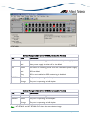
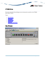
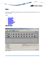
Basic Operations
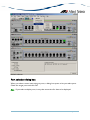
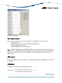
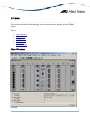
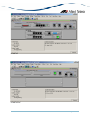
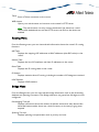
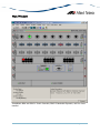
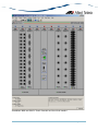
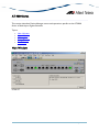
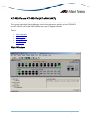
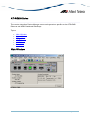
Device Manager's main window shows the main panel of the target device. It has both
common and device-specific menus on its menu bar.
Note - SNMPv3: All device-specific menu options are displayed regardless of the user's view
access security settings.
You can perform operations on the agent by doing a right click on the main panel or by
selecting a menu item from the menu bar. Ports and LEDs on the main panel indicate the
status of the port, system and traffic.
Topics:
•
•
•
•
•
•
Common operations on the main window
Menu for stacked devices
Port selection dialog box
Port status colors
LED status
Utilization
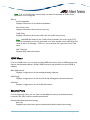
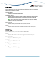
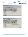
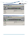
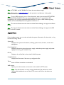
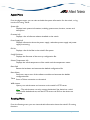
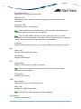
Common operations on the main window
Right clicking on a port
AlliedView™-EMS 3.8 DEVICE MANAGEMENT GUIDE
Page 9 of 330
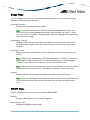
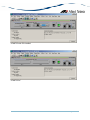
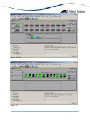
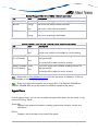
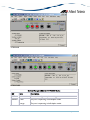
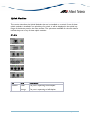
Port
Right clicking on a port opens a pull-down menu specific to the device. Selecting a
menu item opens another window and lets you view and edit MIB information
related to the port. You can also access the same menu from the menu bar.
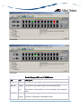
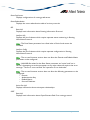
RS-232 Terminal Port
Right clicking on an RS-232 port opens a pull-down menu and lets you choose how
to log into the agent. Depending on the managed device, choose Telnet or WEB
Browser.
Reset Button
Right clicking on a reset button opens a pull-down menu with an option that allows
you to reset the device. (Not available on some devices.)
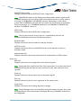
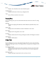
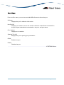
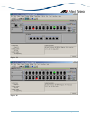
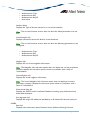
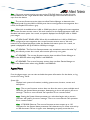
Menu for stacked devices
If the target is a stacked device, some menus have extra subitems to specify a single device
in the stack.
AlliedView™-EMS 3.8 DEVICE MANAGEMENT GUIDE
Page 10 of 330
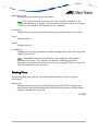
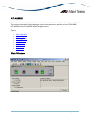
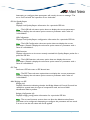
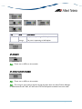
Module submenu
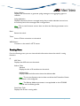
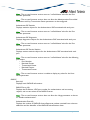
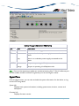
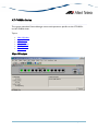
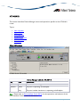
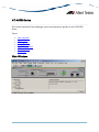
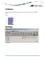
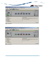
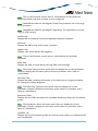
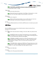
Port selection dialog box
When you select a menu item acting on ports, a dialog box opens to let you select ports.
Check the target ports and click OK.
Note - If you select multiple ports, it may take some time for data to be displayed.
AlliedView™-EMS 3.8 DEVICE MANAGEMENT GUIDE
Page 11 of 330
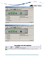
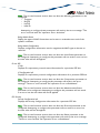
Select Port dialog box
Port status colors
Port status is shown by its color. Port speed is also displayed in the port image.
• Link Up: Green
• Disabled: Red (the port is disabled by an administrator)
• Partitioned/Blocking: Yellow
• Others: Default colour (usually black)
Note - SNMPv3: Depending on the READ VIEW access settings of the User Account Name
used, there is a possibility that Device Manager may not be able to access some MIB values
that control the Port status. When this happens, the affected ports will be shown in the
default color.
LED status
In Device Manager, LEDs do not blink. The meaning of each LED will differ from one device
to another.
Utilization
Utilization is calculated by the following formula.
# of frames x (96 + 64) + octets x 8
Utilization (%) = ----------------------------------------------------- x 100
Port speed (bps) x Sampling Interval(sec)
Basic Operations
AlliedView™-EMS 3.8 DEVICE MANAGEMENT GUIDE
Page 12 of 330
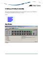
AT-8000 Series
This section describes Device Manager menus and operations specific to the AT-8000
Series.
Topics:
•
•
•
•
•
•
•
Main Window
Agent Menu
Bridge Menu
RMON Menu
Port Menu
Stacking Menu
Expansion Module Notes
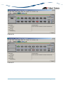
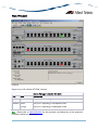
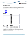
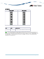
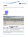
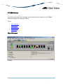
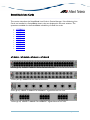
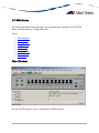
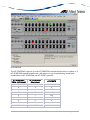
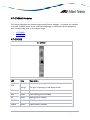
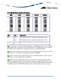
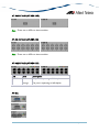
Main Window
AT-8012M
AlliedView™-EMS 3.8 DEVICE MANAGEMENT GUIDE
Page 13 of 330
AT-8012M-QS
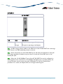
AT-8016F/MT
AlliedView™-EMS 3.8 DEVICE MANAGEMENT GUIDE
Page 14 of 330
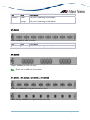
AT-8016F/SC
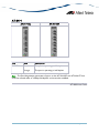
AT-8016F/ST
AlliedView™-EMS 3.8 DEVICE MANAGEMENT GUIDE
Page 15 of 330
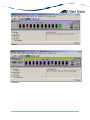
AT-8024
AT-8024GB
AlliedView™-EMS 3.8 DEVICE MANAGEMENT GUIDE
Page 16 of 330
AT-8024M
AT-8026FC
AlliedView™-EMS 3.8 DEVICE MANAGEMENT GUIDE
Page 17 of 330
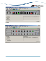
AT-8026T
AT-8088/MT
AlliedView™-EMS 3.8 DEVICE MANAGEMENT GUIDE
Page 18 of 330
AT-8088/SC
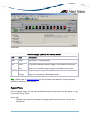
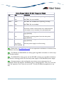
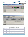
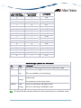
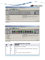
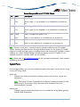
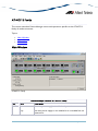
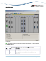
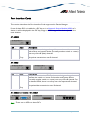
Device Manager LEDs for AT-8000 Series
LED
State
Description
PWR
Green
The switch is receiving power.
MASTER Orange
Gray
DUPLEX Green
Orange
The switch is the master switch of an enhanced stack.
The switch is a slave switch or is not a member of an
enhanced stack.
The port is operating in full-duplex mode.
The port is operating in half-duplex mode.
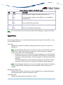
Note - Please refer to Uplink Modules for the operations and behavior of the expansion
modules installed on these devices.
Note - The current firmware version does not allow Device Manager to support the RPS
LED.
Note - When connecting to a slave switch, Device Manager does not automatically replace
the master switch image in the main window with the slave switch image. To view the slave
switch image, click on the Refresh option under the Agent menu.
Note - Device Manager will detect a loss of connection between an AT-8024GB and an AT9410GB when the uplink port on both devices are set to the same speed and mode.
AlliedView™-EMS 3.8 DEVICE MANAGEMENT GUIDE
Page 19 of 330
Note - Connection between an AT-8024GB and an AT-8324 can only be established if the
uplink ports on both devices are configured to auto-negotiate.
Note - Setting the 'Active Protocol Version' to 'STP' and 'Spanning Tree Status' to 'enabled'
will set the Port State parameter of disabled ports to 'blocking'. As a result, port images for
disabled ports will turn yellow.
Note - Setting the 'Active Protocol Version' to 'RSTP' and 'Spanning Tree Status' to 'enabled'
will set the Port State parameter of inactive ports and disabled ports to 'blocking'. As a
result, port images for inactive ports and disabled ports will turn yellow.
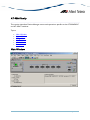
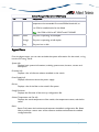
Agent Menu
From the Agent menu, you can view and edit the system information for the device, or log
into the CLI using Telnet.
System Info
Displays basic system information, including system name, location, contact and
description.
Note - Attempting to set the System Contact, System Name, and System Location
parameters to NULL will result in a general error. However, the parameters will still
be temporarily set to NULL. Once the switch is restarted, the original values will be
restored.
Note - The current firmware version accepts up to 40 characters for the System
Contact, System Name and System Location parameters. However, specifying a
value that is exactly 40 characters in length will result in an error message. This
error message may be ignored as the value will still be set successfully.
Firmware Info
Displays firmware version.
Network Info
Displays network-related information such as the addresses of the default gateway
and the agents.
Note - The current firmware version does not allow the Default Domain Name and
the DNS Server parameters to be configured.
Manager Address Info
Displays the IP address of the management station.
Device Info
Displays general information about the switch.
AlliedView™-EMS 3.8 DEVICE MANAGEMENT GUIDE
Page 20 of 330
MAC Address Table
Displays a list of static MAC addresses configured on the switch.
Note - MAC Address Table entries created through a local or telnet management
session will not be visible to Device Manager until the device is restarted.
Reset
Telnet
Resets the switch.
Starts a Telnet connection to the switch.
WEB Browser
Connects to the switch's HTTP server.
Bridge Menu
From the Bridge menu, you can view and edit bridge information such as the forwarding
database and the spanning tree status.
Forwarding Database
Displays the Forwarding Database table.
Discard/Aging Time Info
Displays information about the number of address entries that were learned but
discarded because either there was a lack of memory or the entry's aging timer
expired.
Note - The current firmware version accepts values in the range [10-1000000]
inclusive for the Aging Time parameter.
Spanning Tree Info
Displays spanning tree parameters such as priority and cost.
Note - The current firmware version accepts values in the range [0-65535] inclusive
for the Priority parameter regardless of the active spanning tree protocol version.
Statistics
Displays statistics about frames received/transmitted on the switch port.
RMON Menu
From the RMON menu you can view and edit the RMON MIB.
AlliedView™-EMS 3.8 DEVICE MANAGEMENT GUIDE
Page 21 of 330
Statistics
Displays traffic statistics in the network segment attached to each port.
History Control Table
Displays the RMON History table.
Note - The current firmware version does not support the "historyControlTable"
MIB object of RFC1757. As a result, Device Manager displays the error message
"Failed to get MIB data." when the History Control Table option is selected from the
RMON menu.
Alarm Table
Displays the RMON Alarm table.
Event Table
Displays the RMON Event table.
Event Log
Displays the RMON Event log.
Port Menu
From the Port menu, you can view and edit MIB information about the port.
Utilization
Displays the port's utilization information.
Interface Info
Displays port statistics such as the number of frames received and transmitted on
the port, bytes received and transmitted on the port, and port status.
Note - Valid MIB Set values for the Administration Status parameter are 'up' and
'down'. Attempting to set this parameter to any other value will result in the error
message: "The error occurred with 'Set' operation. Error: bad value."
Error Statistics
Displays error statistics.
Detail Info
Displays detailed port information such as duplex mode.
Note - Valid MIB Set values for the Port Flow Control parameter are 'disable',
'transmit-only', 'receive-only', and 'transmit-and-receive'. However, the current
firmware version does not allow this parameter to be set to 'transmit-only' and
'receive-only' for the following ports:
AlliedView™-EMS 3.8 DEVICE MANAGEMENT GUIDE
Page 22 of 330
•
•
•
•
Expansion module ports
GBIC ports on the AT-8024GB
Fiber optic ports on the AT-8026FC
10/100/1000Base-T ports on the AT-8026T
Note - Valid MIB Set values for the Port State parameter are 'enabled' and 'disabled'.
Attempting to set this parameter to any other value will result in the error message:
"The error occurred with 'Set' operation. Error: bad value."
Note - The current firmware version accepts up to 20 characters for the Port Name
parameter. Attempting to enter more than 20 characters will result in an error
message and may append additional characters to the input value.
Spanning Tree Info
Displays the port's spanning tree parameters.
Note - Setting a port's Port parameter to 'disabled' does not automatically set the
Port State parameter under Detail Info to 'disabled'. As a result, the port's image
may not turn red as expected.
Note - The current firmware version accepts values in the range [0-255] inclusive for
the Port Priority parameter regardless of the active spanning tree protocol version.
Note - The current firmware version accepts values in the range [0-65535] inclusive
for the Port Path Cost parameter regardless of the active spanning tree protocol
version.
Enable
Enables the port.
Note - Under the Sun Solaris platform, the Device Manager application may
terminate abnormally if multiple ports have been selected and each dialog box with
the message "May I set 'atiswitchPortState.n' to up" is clicked one after the other.
Disable
Disables the port.
Note - Under the Sun Solaris platform, the Device Manager application may
terminate abnormally if multiple ports have been selected and each dialog box with
the message "May I set 'atiswitchPortState.n' to down" is clicked one after the other.
Port Mirroring
Displays port mirroring parameters and allows configuration of port mirroring state,
source, and destination.
Note - Valid MIB Set values for the Mirroring Destination Port parameter should
range from 0 to 24. However, the current firmware version allows the user to enter
values up to 65535. Attempting to enter values greater than 65535 will cause the
AlliedView™-EMS 3.8 DEVICE MANAGEMENT GUIDE
Page 23 of 330
new value to be converted to its equivalent wrap-around value; i.e., 65536 will
become 0, 65537 will become 1, and so on.
Note - The current firmware version does not allow the Port Mirroring Status
parameter to be set to 'receive' and 'transmit'. Attempting to do so will result in the
error message: "The error occurred with 'Set' operation. Error: bad value".
Note - By default, the Port Mirroring Status parameter is set to 'disabled' and the
Mirroring Destination Port parameter is set to 0. From this default state, the Port
Mirroring Status parameter can be set to 'both' successfully. However, to set the
Port Mirroring Status parameter back to 'disabled', the Mirroring Destination Port
parameter must be set to a non-zero value.
Note - Any change made to the Mirroring Source Ports parameter while the
Mirroring Destination Port parameter is set to 0 will take effect internally but will
not be reflected in the MIB variable window. To see the change reflected in the MIB
variable window, the Mirroring Destination Port parameter should be set to a nonzero value.
Stacking Menu
From the Stacking menu, you can perform enhanced stacking from any AT-8000 Series
master switch.
Stacking Info
Displays information about the switch's mode. This is also the menu where you can
perform enhanced stacking.
Note - For the Stack Switch Model parameter, additional characters appear after the
model name for discovered AT-8524M, AT-9424T/SP and AT-9424T/GB devices.
Expansion Module Notes
•
Device Manager cannot distinguish between the AT-A45/xx, AT-A47, and ATSTACKM expansion modules. All are displayed with the same GIF image.
•
When both the AT-A45 and AT-A46 expansion modules are present on a device,
the AT-A45 port image may show up as green and its Port Speed parameter may
reflect the value "1 Gbps" even if there is no connection established on the port. To
reflect the correct port image color and port speed, restart the device. This applies
to the following devices:
AT-8016F/xx
AT-8024M
AT-8088/xx
AlliedView™-EMS 3.8 DEVICE MANAGEMENT GUIDE
Page 24 of 330
•
The Spanning Tree Protocol (STP) does not work for the AT-A46 expansion module
when it is installed on an AT-8016F/ST device. As a result, the Port State parameter
of the AT-A46 expansion module port will never be set to 'blocking' and the port
image will never turn yellow.
•
Connection between an AT-A47 expansion module port that is configured to
operate at 1Gbps full duplex and a port on another device can only be established if
the port on the other device is configured to auto-negotiate.
•
For the AT-A47 expansion module, Device Manager will only display the ATA45/AT-A47/AT-STACKM shared GIF image if a GBIC module is present in the
GBIC slot.
•
By default, the Port Speed and Mode parameter of the AT-A47 expansion module
port is set to 'auto sense'. From this mode, the Port Speed and Mode can only be
changed to '1Gbps full-duplex'. However, once set to '1Gbps full-duplex', it can no
longer be set to 'auto sense'.
AT-8000 Series
AlliedView™-EMS 3.8 DEVICE MANAGEMENT GUIDE
Page 25 of 330
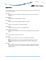
AT-8000S Series
This section describes Device Manager menus and operations specific to the AT-8000S
Series.
Topics:
•
•
•
•
•
•
•
•
Main Window
Agent Menu
Routing Menu
Bridge Menu
IGMP Menu
Security Menu
RMON Menu
Port Menu
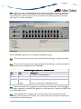
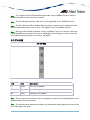
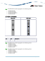
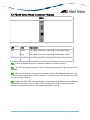
Main Window
AT-8000S/16
AlliedView™-EMS 3.8 DEVICE MANAGEMENT GUIDE
Page 26 of 330
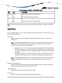
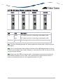
AT-8000S/24, AT-8000S/48 and POE Models
The AT-8000S/24, AT-8000S24/POE, AT 8000S/48 and AT-800S/48 POE can be joined
together into a stack of up to 6 units.
AlliedView™-EMS 3.8 DEVICE MANAGEMENT GUIDE
Page 27 of 330
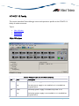
Device Manager LEDs for AT-8000S Series
LED
State
Description
PWR
Green
The switch is receiving power.
STACK ID Orange
DUPLEX
The stacked unit is either the Stacking Master or the
Backup Master.
Gray
The switch is a set to standalone mode.
Green
The stacked unit is a slave switch.
Green
The port is operating in full-duplex mode.
Orange
The port is operating in half-duplex mode.
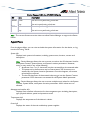
Note - When multiple units of the AT-8000S series are stacked together, port numbering is
continuous based on the Box ID.
•
•
•
•
•
•
Box ID 1 - 1 to 54
Box ID 2 - 55 to 108
Box ID 3 - 109 to 162
Box ID 4 - 163 to 216
Box ID 5 - 217 to 270
Box ID 6 - 271 to 324
This numbering scheme assumes that a unit can have a maximum of 54 ports.
Combo ports on the AT-8000S/24 and AT-8000S/24POE devices are assigned port
numbers 49 and 50.
Note - The current firmware version does not allow Device Manager to detect the presence
of an SFP module in any of the SFP slots unless there is an active connection on the SFP
ports. As a result, SFP images will appear on the device panel only if there is an established
connection on the physical SFP ports.
Agent Menu
From the Agent menu, you can view and edit the system information for the device, or log
into the CLI using Telnet.
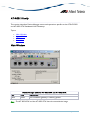
System Info
Displays basic system information, including system name, location, contact and
description.
Note - The current firmware version accepts up to 160 characters for the System
Name parameter.
AlliedView™-EMS 3.8 DEVICE MANAGEMENT GUIDE
Page 28 of 330
Device Info
General Info
Displays common management information.
Active Software File
Displays the currently available images on the flash.
Physical Description
Basic Info
Displays the number of stack units.
Module Info
Displays module information for each unit in the system.
Port Attributes
Displays port information.
Stack Info
Displays information about the stacked devices.
Stack Active Unit ID
Displays the current unit ID of the device after reset.
Note - AT-8000S/16: The current firmware version allows the Active Unit ID
After Reset parameter to be configured but the value is not saved after it is
rebooted.
Power Supply Info
Displays information about the power supply and redundant power supply.
Fan Info
Displays fan status.
Unit General Info
Displays the device's software versions.
Note - The current firmware version accepts up to 160 characters for the
Serial Number and Asset Tag parameters but truncates them to 31 and 16
characters respectively.
Note - The current firmware version is unable to display any value for the
Service Tag parameter.
Unit Environment Info
Displays the device's main power supply and temperature status.
AlliedView™-EMS 3.8 DEVICE MANAGEMENT GUIDE
Page 29 of 330
Software Packages
Displays the device's software packages.
Management Info
General Management
Displays common management information.
Flash File System
Basic Info
Displays the flash file size of the device.
File List
Displays the device's list of files.
Note - The current firmware version does not allow the Row Status
parameter to be configured.
Jumbo Frames
Displays the current jumbo frames status.
Management ACL
Basic Info
Displays basic information about the management access list.
Note - The current firmware version does not allow the Active List Name parameter
to be configured.
Access Lists
Displays information about access lists.
Mid-level Management
Alarm Options
Displays information about alarm options.
Note - The current firmware version does not allow the Alarm Enabling parameter
to be configured.
MIB Tree
Displays information about the device's MIB tree.
Tuning
Agent Diagnostics
Displays diagnostic information about the agent.
Note - The current firmware version returns a 'noSuchName' value for the Location
parameter.
AlliedView™-EMS 3.8 DEVICE MANAGEMENT GUIDE
Page 30 of 330
General Tuning
Displays general tuning information.
Note - The current firmware version accepts values in the range [0-255] inclusive for
the Debug Level parameter.
Max Entries Tuning
Displays information about the maximum entries in tuning.
Note - The current firmware version does not allow the following parameters to be
configured:
Max IP Next Hop Entries After Reset
Max IP Prefixes After Reset
Max IP ECMP Entry After Reset
Max IP Interfaces After Reset
TCP Tuning
Displays the memory pool size for tcp tuning.
Radius Tuning
Displays the memory pool size for radius tuning.
Syslog Tuning
Displays the current cache size and its size after reset.
Management ACL Tuning
Displays the current number of access rules and the number after reset.
SSH Tuning
Displays the current number of the maximum number of authorized keys and its
value after reset.
Terminal Sessions
Displays the current number of maximum sessions and its value after reset.
DNS Client Tuning
Displays the maximum values of the cache entries and the negative cache entries
before and after reset.
Tuning Parameters
Displays the current value, value after reset, default value, minimum and maximum
value of the different tuning parameters.
Host Parameters
Displays the corresponding value of the different host parameters.
AlliedView™-EMS 3.8 DEVICE MANAGEMENT GUIDE
Page 31 of 330
Terminal Debug Mode
Displays the terminal debug mode password.
Note - The current firmware version does not allow the Terminal Debug Mode
Password to be configured.
Telnet
Basic Info
Displays the basic telnet information.
Telnet Sessions
Displays the login time, client ip address and telnet session status.
CLI Info
Displays information if the file is enabled or not.
LCLI Info
Displays information about the device's Telnet sessions and SSH sessions if enabled
or not.
Note - Valid MIB Set values for the History Size, Telnet History Size and SSH History
Size parameters are in the range [10-160] inclusive. Attempting to set these
parameters to a value outside of the valid range will result in the error message:
"The error occurred with 'Set' operation. Error: bad value."
RS-232
Web
Displays the configuration of the baud rate of the device.
Displays the configuration about the HTTP and HTTPS Port the device used.
Date and Time
Time Synchronization
Displays the configuration about the device's date/time and time zone.
Note - The current firmware version does not allow the Managed Time and Managed
Date parameters to be configured.
Note - The current firmware version does not allow the DST End and DST Start
parameters to be configured.
Note - Valid MIB Set values for the DST Offset parameter should range from 1 to
1440. However, the current firmware version allows the user to enter values in the
range [-2147483648 to 2147483647] inclusive. Attempting to enter values greater
than 2147483647 will cause the new value to be converted to its equivalent wraparound value; i.e., 2147483648 will become -2147483648, 2147483649 will become 2147483647, and so on.
AlliedView™-EMS 3.8 DEVICE MANAGEMENT GUIDE
Page 32 of 330
SNTP/NTP Client Config
Displays information about SNTP/NTP client configuration.
Note - Valid MIB Set values for the Polling Interval parameter should range from 60
to 86400. However, the current firmware version allows the user to enter values in
the range [-2147483648 to 2147483647] inclusive. Attempting to enter values
greater than 2147483647 will cause the new value to be converted to its equivalent
wrap-around value; i.e., 2147483648 will become -2147483648, 2147483649 will
become -2147483647, and so on.
SNTP Config
Displays information about SNTP client configuration.
Note - The current firmware version returns a 'noSuchName' value for the
Broadcast Poll State and Anycast Poll State parameters.
Broadcast Mode
Displays information about broadcast mode per interface.
SNTP Server Info
Displays information about trusted SNTP servers to be queried in unicast or
broadcast mode.
Authentication Keys
Displays information about keys information for authentication of NTP packets.
System Log
Basic Info
Displays information and configuration of the device's log files.
Note - Setting the Clear Log File and Clear Cache parameters to a value other than 0
will delete the log file and clear the cache memory but the value used will not be
retained.
Event Log
Displays information about events sent to the system log file.
Error Log
Displays information about errors registered to the system cache.
Syslog Device
Displays information about Syslog diagnostic messages.
Note - Device Manager does not handle 8-bit string parameters correctly. As a result,
the Syslog Device Control parameter will display the string "00000000" and will not
be configurable.
AlliedView™-EMS 3.8 DEVICE MANAGEMENT GUIDE
Page 33 of 330
Syslog Collector
Displays the information to generate syslog messages to an aggregating agent or
collector.
Syslog Application
Displays information about a managed entity that provides individual control over
the severity level of the messages that it will generate.
Note - The current firmware version does not allow the Severity parameter to be
configured.
Reset
Telnet
Resets the switch.
Starts a Telnet connection to the switch.
WEB Browser
Connects to the switch's HTTP server.
Routing Menu
From the Routing menu, you can view and edit information about the switch's routing
functions.
IP
ARP Table
Displays the ARP cache on the switch.
Address Table
Standard
Displays the list of IP interfaces on the switch.
Additional Info
Displays additional information about the address table.
Note - The current firmware version does not allow the IP Interface Owner
parameter to be configured.
Note - The Backup Address parameter is not applicable to the AT-8000S
module and should be ignored.
Static Route Table
Displays the IP static routing table.
AlliedView™-EMS 3.8 DEVICE MANAGEMENT GUIDE
Page 34 of 330
Note - The current firmware version does not allow the Routing Type parameter to
be set to ‘local’ for all models except the AT-8000S/16. For the AT-8000S/16, the
Routing Type parameter cannot be set to ‘remote.’
IP Statistics
Displays statistics about IP routing, including the number of IP datagrams received.
Note - The current firmware version does not allow the Forwarding Status
parameter to be configured.
ARP Table Config
Displays configuration information about ARP.
I/F Name-Address Translation
Displays information about the IP interface's name translated to an IP interface
address.
TFTP
Displays configuration information about the TFTP.
Note - The current firmware version does not allow the Get Config File parameter
to be configured to receive image/config/boot files from a TFTP server.
Note - The current firmware version does not allow the Send Config File parameter
to be configured to send config/image/boot files to a TFTP server.
UDP
Listener Info
Displays UDP listener information.
UDP Statistics
Displays UDP statistics.
TCP
Connection Info
Displays TCP connection-specific information.
Note - The current firmware version does not allow the Connection Status
parameter to be configured.
TCP Statistics
Displays TCP statistics.
CIDR
Route Number
Displays the number of valid CIDR entries.
AlliedView™-EMS 3.8 DEVICE MANAGEMENT GUIDE
Page 35 of 330
Route Table
Displays the CIDR routing tables.
Note - The current firmware version does not allow the following parameters to be
configured:
o Destination Port Number
o Routing Protocol MIB
o Destination Metric 2
o Destination Metric 3
o Destination Metric 4
o Destination Metric 5
Note - The current firmware version does not allow the Routing Type parameter to
be set to ‘local’ for all models except the AT-8000S/16. For the AT-8000S/16, the
Routing Type parameter cannot be set to ‘remote.
ICMP
ICMP Statistics
Displays ICMP Statistics.
Error Messages
Displays the variable that controls the ability to generate ICMP error messages.
DNS Resolver
Resolver Config
Displays information about the DNS client.
Note - The current firmware version does not allow the Reset parameter to be set
to "reset".
Basic Counters
Displays information about basic DNS couters.
Counters by OpCode
Displays information about the current count of resolver queries and answers.
Counters by Response Code
Displays information about the current count of responses to resolver queries.
Lame Delegation Overflows
Displays information about number of times the resolver attempted to add an entry
to the lame delegation table.
Cache Info
Displays information about a collection of objects providing access to and control of
a DNS resolver's cache.
AlliedView™-EMS 3.8 DEVICE MANAGEMENT GUIDE
Page 36 of 330
Negative Cache Info
Displays information about a collection of objects providing access to and control of
a DNS resolver's negative response cache.
Additional Counters
Displays information about a collection of objects providing further instrumentation
applicable to many but not all DNS resolvers.
Bridge Menu
From the Bridge menu, you can view and edit bridge information such as the forwarding
database and the spanning tree status.
Forwarding Database
Displays the Forwarding Database table.
Aging Time Info
Displays information about the device's aging time.
Spanning Tree Info
STP
Standard
Displays the spanning tree information such as the STP version and path cost.
Additional Info
Displays additional STP information like supported type.
MSTP
Basic Info
Displays the basic information about MSTP.
Instance Info
Displays information that contains Mstp instance specific information for the
Multiple Spanning Tree Protocol.
VLAN Info
Displays information about the allocation of vlans to groups.
Statistics
Displays statistics about frames received/transmitted on the switch port.
Basic Bridge Info
Displays basic bridge information.
Bridge Port Info
Displays statistics about frames received/transmitted on the switch port.
AlliedView™-EMS 3.8 DEVICE MANAGEMENT GUIDE
Page 37 of 330
Note - The current firmware version does not allow the Number of Traffic Class
parameter to be configured.
802.1p
Device Capabilities
Displays information on the device capabilities.
Port Priority Group
Displays information about the port priority.
Traffic Class
Displays information about the traffic class and traffic class priority.
Note - Valid MIB Set values for the Traffic Class parameter are in the range [0-3]
inclusive. Attempting to set this parameter to a value outside of the valid range will
result in the error message: “The error occurred with ‘Set’ operation. Error: bad
value.”
MAC Table Info
Displays MAC table information.
IGMP Menu
From the IGMP menu, you can view and edit IGMP information such as IGMP queries and
reports sent between devices, VLAN's IGMP functions and interfaces on which IGMP is
enabled.
MAC Multicast Info
Displays configurations of the enabling/disabling multicast.
IGMP Config
Displays configurations of the Internet Group Management Protocol function.
VLAN Info
Displays configurations of the VLAN information.
Security Menu
From the Security menu, you can view and edit different security and authentication
protocols SSL, SSH, and port-based authentication.
Authentication/Authorization/Accounting
Basic Info
Displays basic information about Authentication/Authorization/Accounting.
AlliedView™-EMS 3.8 DEVICE MANAGEMENT GUIDE
Page 38 of 330
Note - The current firmware version does not allow the EAP Current Method List
parameter to be configured.
Method Lists
Displays information about all method lists.
Note - The current firmware version does not allow the Row Status parameter to be
configured.
Lines
Displays information about all lines, their passwords and their authorization levels.
Note - The current firmware version does not allow the Password, Row Status and
Password Valid Time parameters to be configured.
Note - The current firmware version is unable to display any value for the Password
Expiry Date parameter.
Local Users
Displays information about all usernames, their passwords and their authorizations.
Note - The current firmware version does not allow the User Password, Row Status
and Password Valid Time parameters to be configured.
Note - The current firmware version is unable to display any value for the Password
Expiry Date parameter.
Authenticated Users
Displays all the current users that have been authenticated.
EAP Method Lists
Displays information about all EAP method lists.
Note - The current firmware version does not allow the Row Status parameter to be
configured.
Port-based Authentication
PAE Port Info
Displays the system level information for each port supported by the Port Access
Entity.
Note - The current firmware version returns a 'noSuchName' value for the Port
Number parameter.
Authenticator PAE Info
Displays configuration objects for the Authenticator PAE associated with each port.
AlliedView™-EMS 3.8 DEVICE MANAGEMENT GUIDE
Page 39 of 330
Note - The current firmware version returns a 'noSuchName' value for the Port
Number parameter.
Note - The current firmware version does not allow the Administrative Controlled
Directions and Key Transmission Status parameters to be configured.
Authenticator PAE Statistics
Displays statistics objects for the Authenticator PAE associated with each port.
Note - The current firmware version returns a 'noSuchName' value for the Port
Number parameter.
Authenticator PAE Diagnostics
Displays diagnostics objects for the Authenticator PAE associated with each port.
Note - The current firmware version returns a 'noSuchName' value for the Port
Number parameter.
Authenticator PAE Session Statistics
Displays session statistics objects for the Authenticator PAE associated with each
port.
Note - The current firmware version returns a 'noSuchName' value for the following
parameters:
o Port Number
o Received Octets
o Transmitted Octets
o Received Frames
o Transmitted Frames
Note - The current firmware version is unable to display any value for the User
Name parameter.
RADIUS
Basic Info
Displays basic RADIUS information.
RADIUS Server Info
Displays the IP address, UDP port number for authentication and accounting
request, and current status of the RADIUS server.
Note - The current firmware version does not allow the Usage parameter to be set
to 'wireless authentication'.
Authentication Client Info
Displays the number of RADIUS Access-Response packets received from unknown
addresses and the identifier of the RADIUS authentication client.
AlliedView™-EMS 3.8 DEVICE MANAGEMENT GUIDE
Page 40 of 330
Note - The current firmware version is unable to display any value for the Client ID
parameter.
Authentication Server Info
Displays the list of RADIUS authentication servers with which the client shares a
secret.
Accounting Client Info
Displays the number of RADIUS Access-Response packets received from unknown
addresses and the identifier of the RADIUS accounting client.
Note - The current firmware version is unable to display any value for the Client ID
parameter.
Accounting Server Info
Displays the list of RADIUS accounting servers with which the client shares a secret.
TACACS+
Basic Info
Displays basic TACACS+ information.
TACACS+ Server Info
Displays information about TACACS+ server.
Secure Shell
SSH Server
Displays information about the status of public key authentication and the type of
regenerated host key.
Note - Configuring the Regenerate Host Key parameter will result in the error
message: "The error occurred with 'Set' operation. Error: time out occurred" but a
key will still be successfully generated.
SSH Client
Displays information about the user name ssh client will use and the value of the
regenerated self key.
Note - The current firmware version accepts up to 60 characters for the User Name
parameter.
Note - Setting the Regenerate Self Key parameter to "rsa" or "dsa" will result in the
error message: "The error occurred with 'Set' operation. Error: time out occurred".
Connection with the AT-8000S device will be lost and the only way to re-establish
connection will be to perform a manual reset.
Note - The current firmware version does not allow the Regenerate Self Key
parameter to be set to 'rsa1'.
AlliedView™-EMS 3.8 DEVICE MANAGEMENT GUIDE
Page 41 of 330
Secure Socket Layer
Basic Info
Displays basic SSL information.
Note - The current firmware version does not allow the Certificate Save parameter
to be configured.
Certificate Generation
Displays information about the generated keys and self signed certificates.
Note - The current firmware version does not allow any of the parameteres under
this table to be configured.
Export Certificate
Displays information about the saved data from RAM and flash.
Import Certificate
Displays information about the copied external certificate of the device.
RMON Menu
From the RMON menu you can view and edit the RMON MIB.
Statistics
Displays traffic statistics in the network segment attached to each port.
History Control Table
Displays the RMON History table.
Alarm Table
Displays the RMON Alarm table.
Event Table
Displays the RMON Event table.
Event Log
Displays the RMON Event log.
Port Menu
From the Port menu, you can view and edit MIB information about the port.
Utilization
Displays the port's utilization information.
AlliedView™-EMS 3.8 DEVICE MANAGEMENT GUIDE
Page 42 of 330
Note - The current firmware version does not allow Device Manager to display
Utilization information.
Interface Info
Standard
Displays port statistics such as the number of frames received and transmitted on
the port, bytes received and transmitted on the port, and port status.
Note - The current firmware version does not allow the Promiscuous Mode
parameter to be configured.
Note - The current firmware version returns a "noSuchName" value for the
following parameters:
o Received Error Packets
o Transmitted Error Packets
o Transmitted Buffer Length
o Received Bytes (HC)
o Received Unicast Packets (HC)
o Received Multicast Packets (HC)
o Received Broadcast Packets (HC)
o Transmitted Bytes (HC)
o Transmitted Unicast Packets (HC)
o Transmitted Multicast Packets (HC)
o Transmitted Broadcast Packets (HC)
Additional Info
Displays additional information about the port's interface info.
Error Statistics
Standard
Displays error statistics for the port.
Note - The Ethernet Chip Set parameter is not applicable to the AT-8000S series
and should be ignored.
Note - The current firmware version returns a "noSuchName" value for the
following parameters:
o Alignment Error Frames
o Multi Collision Frames
o SQE Test Errors
o Deferred Transmissions
o Excessive Collisions
o Internal MAC Transmit Errors
o Carrier Sense Errors
o Symbol Errors
Additional Info
Displays information about a table containing 64-bit versions of error counters.
AlliedView™-EMS 3.8 DEVICE MANAGEMENT GUIDE
Page 43 of 330
Note - The current firmware version is unable to display any value for the Port
Number and Alignment Error Frames (HC) parameters.
Note - The current firmware version returns a ‘noSuchName’ value for the Internal
MAC Transmit Errors (HC) and Internal MAC Received Errors (HC) parameters.
Detail Info
Displays detailed port information such as duplex mode.
Note - The current firmware version does not allow the following parameters to be
configured:
• Tagged Mode
• Default Priority
• Row Status
• Port Flow Control Config
• Port Speed
• Reactivate
• Combo Ethernet Config
Note - Device Manager does not handle 8-bit string parameters correctly. As a result,
the Autonegotiation Capabilities Config parameter will display an unrecognizable
value and will not be configurable. The Autonegotiation Capabilities Status and
Remote Autonegotiation Capabilities parameters will also display unrecognizable
values.
Note - The Physical Address Type parameter is not applicable to the AT-8000S
series and should be ignored.
Note - The combo ports will not display the Port Context Menu on right-mouse
click if logged-on in SNMPv3 mode using a user account with no read-write access
to the Transceiver Type parameter.
Spanning Tree Info
STP
Standard
Displays the port's spanning tree parameters.
Additional Info
Displays a list of information maintained by every port about the Spanning
Tree Protocol state for that port.
MSTP
MSTI
Displays a list of information maintained by every pair <msti, port> about the
Spanning Tree Protocol state for that pair.
CIST
Displays a list of information maintained by every port of the CIST.
AlliedView™-EMS 3.8 DEVICE MANAGEMENT GUIDE
Page 44 of 330
Enable
Disable
Enables the port.
Disables the port.
Port Lock
Basic Info
Displays basic information about port lock.
Interfaces Range
Displays information about port lock interfaces range.
MAC Control
MAC Control Sublayer
Displays information about the MAC Control sublayer on a single ethernet-like
interface.
Note - The current firmware version returns a 'noSuchName' value for the Unknown
Opcodes Received and Unknown Opcodes Received (HC) parameters.
MAC Control PAUSE
Displays information about the MAC Control PAUSE function on a single ethernetlike interface.
Note - Valid MIB Set values for the PAUSE Config parameter are "disabled" and
"enabledXmitAndRcv". Attempting to set this parameter to any other value will
result in the error message: "The error occurred with 'Set' operation. Error: bad
value."
Note - The current firmware version returns a "noSuchName" value for the
Received Frames (HC) and Transmit Frames (HC) parameters.
QoS
Basic Info
Displays basic information about QoS.
Note - Although the current firmware allows the QoS Mode parameter to be set to
'service', the value 'service' is not a valid MIB Set value.
Note - Valid MIB Set values for the Basic Mode parameter are 'vpt', 'dscp' and ‘dscpmutation’. However, setting the Basic Mode parameter to ‘dscp-mutation’ will result
in the error message "The error occurred with 'Set' operation. Error: gen Error." In
addition, attempting to set this parameter to ‘none’ or ‘tcp-udp’ will result in the
error message: "The error occurred with 'Set' operation. Error: bad value."
AlliedView™-EMS 3.8 DEVICE MANAGEMENT GUIDE
Page 45 of 330
Tail Drop/WRED
Displays information about the Tail Drop or WRED parameters and the EF of WRR
parameters.
Note - The current firmware version does not allow the Row Status parameter to be
configured.
DSCP Mutation
Displays information about the new DSCP for the packet.
DSCP Remark
Displays information about the DSCP remark packet.
Note - The current firmware version does not allow the New DSCP parameter to
be configured.
QoS to Queue
Displays information about the queue ID.
Note - Valid MIB Set values for the Queue ID parameter are in the range [1-4]
inclusive. Attempting to set this parameter to a value outside of the valid range will
result in the error message: "The error occurred with 'Set' operation. Error: bad
value."
DSCP to Queue
Displays information about the queue number.
Note - Valid MIB Set values for the Queue ID parameter are in the range [1-4]
inclusive. Attempting to set this parameter to a value outside of the range valid
range will result in the error message: "The error occurred with 'Set' operation.
Error: bad value."
UDP Port to DSCP
Displays information about the EF management for the system.
Note - Valid MIB Set values for the Priority parameter are in the range [1-4] inclusive.
Attempting to set this parameter to a value outside of the range valid range will
result in the error message: "The error occurred with 'Set' operation. Error: bad
value."
DSCP to DP
Displays information about the DSCP to DP table.
Note - Valid MIB Set values for the DP parameter are '0' and '2'. Attempting to set
this parameter to any other value will result in the error message: "The error
occurred with 'Set' operation. Error: bad value."
AlliedView™-EMS 3.8 DEVICE MANAGEMENT GUIDE
Page 46 of 330
Default VPT to Queue
Displays information about the VLAN tag priority.
Default DSCP to Queue
Displays information about the setting of default dscp to queue map.
Queue Profiles
Displays information about the queue management profiles.
Note - The current firmware version does not allow the Queue Value parameters to
be configured.
Port Trunking
Basic Info
Displays basic information about port trunking.
Note - The current firmware version does not allow any of the parameters under
this table to be configured.
Balancing Criteria
Displays information about Aggregate Index.
Note - The current firmware version does not allow the Balance Layer, Used
Addresses and Broadcast Type parameters to be configured.
Aggregator Info
Displays information about every Aggregator that is associated with this system.
Note - Valid MIB Set values for the Actor Administrative Key parameter are in the
range [1 - 65535] inclusive. Attempting to set this parameter to a value outside of
the valid range will result in the error message: “The error occurred with ‘Set’
operation. Error: bad value.”
Aggregator Port List
Displays Link Aggregation Control information for every Aggregation Port
associated with this device.
Aggregation Port Info
Displays a list of Link Aggregation Control configuration parameters for each
Aggregation Port on this device.
Note - The current firmware version returns a 'noSuchName' value for the Port
Number parameter.
Note - Device Manager does not handle 8-bit string parameters correctly. As a result,
the Actor Administrative Status and Partner Administrative Status parameters will
display unrecognizable values and will not be configurable. The Actor Operational
AlliedView™-EMS 3.8 DEVICE MANAGEMENT GUIDE
Page 47 of 330
Status and Partner Operational Status parameters will also display unrecognizable
values.
Note - The current firmware version does not allow the Actor Administrative Key
and Partner Administrative System ID parameters to be configured.
Storm Control
Basic Info
Displays basic information about storm control.
Storm Control Protection
Displays information about the storm control protection per port.
Note - Only the Broadcast Enable and Multicast Enable parameters can be configured.
Storm Control Group
Displays information about group id for each supported frame type defined per port.
AT-8000S Series
AlliedView™-EMS 3.8 DEVICE MANAGEMENT GUIDE
Page 48 of 330
AT-8124
This section describes Device Manager menus and operations specific to the AT-8124
switch.
Topics:
•
•
•
•
•
Main Window
Agent Menu
Bridge Menu
RMON Menu
Port Menu
Main Window
AT-8124
Device Manager LEDs for AT-8124
LED
State
Description
PWR
Green
The switch is receiving power.
DUPLEX Green
Gray
The port is operating in full-duplex mode.
The port is operating in half-duplex mode.
AlliedView™-EMS 3.8 DEVICE MANAGEMENT GUIDE
Page 49 of 330
Agent Menu
From the Agent menu, you can view and edit the system information for the device or log
into the CLI using telnet.
System Info
Displays basic system information, including system name, location, contact and
description.
Network Info
Displays network-related information such as the device's IP address, and the default
gateway address.
Firmware Info
Displays the version of the software running on the managed device.
Manager Address Info
Displays the management station's IP address.
Reset
Resets the switch.
Hot Reset
Performs a software reset. This takes less time than a Cold Reset.
Cold Reset
Performs a hardware reset. This takes more time than a Hot Reset.
Telnet
Connects to the switch's Telnet service.
Bridge Menu
From the Bridge menu, you can view and edit bridge information such as the forwarding
database and the spanning tree status.
Forwarding Database
Displays the Forwarding Database table.
Discard/Aging Time Info
Displays information about the number of address entries that were learned but
discarded because either there was a lack of memory or the entry's aging timer
expired.
Spanning Tree Info
Displays spanning tree parameters such as priority and cost.
AlliedView™-EMS 3.8 DEVICE MANAGEMENT GUIDE
Page 50 of 330
Statistics
Displays statistics about frames received/transmitted on the switch port.
RMON Menu
From the RMON menu you can view and edit the RMON MIB.
Note - Since there may be a large quantity of RMON data, it may take some time for the
information to appear.
Statistics
Displays traffic statistics about the network segment attached to each port.
History Control Table
Displays the RMON History table.
Alarm Table
Displays the RMON Alarm table.
Event Table
Displays the RMON Event table.
Event Log
Displays the RMON Event log.
Port Menu
From the Port menu, you can view and edit MIB information about the port.
Utilization
Displays the port's utilization information.
Interface Info
Displays port statistics such as the number of frames received and transmitted on
the port, bytes received and transmitted on the port, and port status.
Detail Info
Displays port traffic statistics such as the number of frames received/transmitted on
the port.
Error Statistics
Displays error information.
AlliedView™-EMS 3.8 DEVICE MANAGEMENT GUIDE
Page 51 of 330
Detail Status
Displays detailed port information such as duplex mode.
Spanning Tree Info
Displays the port's spanning tree parameters.
Enable
Disable
Enables the port.
Disables the port.
AT-8124
AlliedView™-EMS 3.8 DEVICE MANAGEMENT GUIDE
Page 52 of 330
AT-8124XL (V2)
This section describes Device Manager menus and operations specific to the AT-8124XL
(V2) switch.
Topics:
•
•
•
•
•
Main Window
Agent Menu
Bridge Menu
RMON Menu
Port Menu
Main Window
AT-8124XL (V2)
Device Manager LEDs for AT-8124XL (V2)
LED
State
Description
PWR
Green
The switch is receiving power.
DUPLEX Green
Orange
The port is operating in full-duplex mode.
The port is operating in half-duplex mode.
AlliedView™-EMS 3.8 DEVICE MANAGEMENT GUIDE
Page 53 of 330
Agent Menu
From the Agent menu, you can view and edit the system information for the device, or log
into the CLI using Telnet.
System Info
Displays basic system information, including system name, location, contact and
description.
Note - Device Manager allows the user to enter up to 255 characters for the System
Contact, System Name, and System Location parameters but truncates them to 64
characters. NULL values are not accepted.
Firmware Info
Displays firmware version.
Network Info
Displays network-related information such as the addresses of the default gateway
and the agents.
DHCP Info
Displays DHCP information including the DHCP System Group and DHCP Timer
Group.
Manager Address Info
Displays the IP address of the management station.
Reset
Telnet
Resets the switch.
Starts a Telnet connection to the switch.
WEB Browser
Connects to the switch's HTTP server.
Bridge Menu
From the Bridge menu, you can view and edit bridge information such as the forwarding
database and the spanning tree status.
Forwarding Database
Displays the Forwarding Database table.
AlliedView™-EMS 3.8 DEVICE MANAGEMENT GUIDE
Page 54 of 330
Discard/Aging Time Info
Displays information about the number of address entries that were learned but
discarded because either there was a lack of memory or the entry's aging timer
expired.
Spanning Tree Info
Displays spanning tree parameters such as priority and cost.
Statistics
Displays statistics about frames received/transmitted on the switch's ports.
RMON Menu
From the RMON menu you can view and edit the RMON MIB.
Statistics
Displays traffic statistics in the network segment attached to each port.
History Control Table
Displays the RMON History table.
Alarm Table
Displays the RMON Alarm table.
Event Table
Displays the RMON Event table.
Event Log
Displays the RMON Event log.
Port Menu
From the Port menu, you can view and edit MIB information about the port.
Utilization
Displays the port's utilization information.
Interface Info
Displays port statistics such as the number of frames received and transmitted on
the port, bytes received and transmitted on the port, and port status.
Note - Valid MIB Set values for the Administration Status parameter are 'up' and
'down'. All other values are ignored.
AlliedView™-EMS 3.8 DEVICE MANAGEMENT GUIDE
Page 55 of 330
Detail Info
Displays detailed port information such as duplex mode.
Note - Enabling/Disabling the Port STP Configuration parameter for one port
enables/disables STP for all ports.
Note - Attempting to modify the Port Speed and Mode parameter from 'auto sense'
to '1Gbps half-duplex' or '1Gbps full-duplex' will result in the following:
• An error message: "The error occurred with 'Set' operation. Error: gen
Error"
• Port Speed and Mode parameter value changing to '100Mbps half-duplex'
Note - The current firmware version does not allow the Port Bridge ID parameter
to be configured. Attempting to configure this parameter will result in the error
message: "The error occurred with 'Set' operation. Error: bad value."
Note - When a port is set to 'auto sense' and is connected to a half duplex port on
another device, its corresponding Duplex LED on the device image turns green
instead of orange.
Note - The current firmware version does not allow the Port Back Pressure
parameter to be configured. Attempting to configure this parameter will result in the
error message: "The error occurred with 'Set' operation. Error: time out occurred."
Note - The Port Transmit Pacing Configuration parameter is not applicable to the
AT-8124XL (V2).
Note - The current firmware version does not allow the Port VLAN Tag Priority and
the Port QoS Priority parameters to be configured. Attempting to configure these
parameters will result in the error message: "The error occurred with 'Set'
operation. Error: bad value."
Note - Valid MIB Set values for the Port State parameter are 'enabled' and 'disabled'.
Attempting to set this parameter to any other value will result in the error message:
"The error occurred with 'Set' operation. Error: bad value.".
Spanning Tree Info
Displays the port's spanning tree parameters.
Enable
Disable
Enables the port.
Disables the port.
Port Mirroring
AlliedView™-EMS 3.8 DEVICE MANAGEMENT GUIDE
Page 56 of 330
Displays port mirroring parameters and allows configuration of port mirroring state,
source, and destination.
IGMP Snooping
Displays the current state of IGMP Snooping and allows reconfiguration.
AT-8124XL (V2)
AlliedView™-EMS 3.8 DEVICE MANAGEMENT GUIDE
Page 57 of 330
AT-8200XL Series
This section describes Device Manager menus and operations specific to the AT8216FXL/SC and AT-8224XL switches.
Topics:
•
•
•
•
•
•
Main Window
Agent Menu
Bridge Menu
RMON Menu
Port Menu
Expansion Module Notes
Main Window
AT-8216FXL/SC
AlliedView™-EMS 3.8 DEVICE MANAGEMENT GUIDE
Page 58 of 330
AT-8224XL
Device Manager LEDs for AT-8200XL Series
LED
State
Description
PWR
Green
The switch is receiving power.
RPS
Green
An optional redundant power supply is connected to the switch.
Gray
There is no redundant power supply connected to the switch.
DUPLEX Green
Orange
The port is operating at full-duplex mode.
The port is operating at half-duplex mode.
Note - Please refer to Uplink Modules for the operations and behavior of the expansion
modules installed on these devices.
Agent Menu
From the Agent menu, you can view and edit the system information for the device, or log
into the CLI using Telnet.
System Info
Displays basic system information, including system name, location, contact and
description.
AlliedView™-EMS 3.8 DEVICE MANAGEMENT GUIDE
Page 59 of 330
Note - The current firmware version allows the user to enter up to 64 characters
for the System Contact and the System Location parameters and up to 20
characters for the System Name parameter.
Note - The current firmware version appends a period '.' and the value of the Default
Domain Name parameter to the value of the System Name parameter.
Firmware Info
Displays the firmware version of the switch.
Network Info
Displays network-related information such as the addresses of the default gateway
and the agents.
Manager Address Info
Displays the IP address of the management station.
Device Info
Displays general information about the switch.
Note - The Security Action parameter has a fixed value of 'do nothing' and cannot be
modified.
Note - The Security Configuration parameter has a fixed value of 'disabled' and
cannot be modified.
Note - Valid MIB Set values for the HOL Configuration and Logging Configuration
parameters are 'on' and 'off'. Attempting to set these parameters to any other value
will result in the error message: "The error occurred with 'Set' operation. Error: bad
value".
Note - Valid MIB Set values for the QoS Configuration parameter are:
• mode 1
• mode 2
• mode 3
• mode 4
• mode 5
• mode 6
• mode 7
• mode 8
Attempting to set this parameter to any other value will result in the error message:
"The error occurred with 'Set' operation. Error: bad value".
DHCP Info
Displays the DHCP information about the switch.
AlliedView™-EMS 3.8 DEVICE MANAGEMENT GUIDE
Page 60 of 330
Diagnostics
Displays the operating status of the switch's components such as power supply and
system fans.
Note - The current firmware version returns 'non-supported' for the following
parameters:
• Fan Speed 3
• 3.3V Power
• 2.5Va Power
• 2.5Vb Power
• 2V Power
• CPU Temperature
Reset
Resets the switch.
Console Settings
Displays the current settings of the console.
Telnet
Starts a Telnet connection to the switch.
WEB Browser
Connects to the switch's HTTP server.
Note - The current firmware version is unable to display the AT-8216FXL/SC device
image in the Omega web management session interface.
Bridge Menu
From the Bridge menu, you can view and edit bridge information such as the forwarding
database and the spanning tree status.
Bridge Info
Displays basic bridge information such as the LAN ID, bridge address, number of
parts controlled by the bridging entity and the bridge type.
Forwarding Database
Displays the Forwarding Database table.
Note - The current firmware version does not allow the VLAN Name parameter to
be configured. Attempting to configure this parameter will result in the error
message: "The error occurred with 'Set' operation. Error: noSuchName."
AlliedView™-EMS 3.8 DEVICE MANAGEMENT GUIDE
Page 61 of 330
Discard/Aging Time Info
Displays information about the number of address entries that were learned but
discarded because either there was a lack of memory or the entry's aging timer
expired.
Spanning Tree Info
Displays spanning tree parameters such as priority and cost.
Statistics
Displays statistics about frames received/transmitted on the switch port.
RMON Menu
From the RMON menu you can view and edit the RMON MIB.
Statistics
Displays traffic statistics in the network segment attached to each port.
History Control Table
Displays the RMON History table.
Alarm Table
Displays the RMON Alarm table.
Event Table
Displays the RMON Event table.
Event Log
Displays the RMON Event log.
Port Menu
From the Port menu, you can view and edit MIB information about the port.
Utilization
Displays the port's utilization information.
Interface Info
Displays port statistics such as the number of frames received and transmitted on
the port, bytes received and transmitted on the port, and port status.
Note - Valid MIB Set values for the Administration Status parameter are 'up' and
'down'. Attempting to set this parameter to any other value will result in the error
message: "The error occurred with 'Set' operation. Error: bad value."
AlliedView™-EMS 3.8 DEVICE MANAGEMENT GUIDE
Page 62 of 330
Error Statistics
Displays error statistics.
Detail Info
Displays detailed port information such as duplex mode.
Note - The Port Flow Control parameter has a fixed value of 'not supported' and
cannot be modified.
Note - When the Port Speed and Mode parameter of an AT-8224XL fixed port is set
to 'auto sense' and the port is connected to a full duplex port on another device, its
corresponding Duplex LED on the device image turns orange instead of green.
Note - The current firmware version allows active ports to be disabled. However,
the disabled ports' Port Link State parameter retains the value 'on-line'.
Note - Valid MIB Set values for the Port State parameter are 'enabled' and 'disabled'.
Attempting to set this parameter to any other value will result in the error message:
"The error occurred with 'Set' operation. Error: bad value."
Note - Attempting to configure the Port Speed and Mode parameter of an AT8216FXL/SC fixed port to '10Mbps half-duplex' or '10Mbps full-duplex' will
automatically set it to '100Mbps half-duplex' or '100Mbps full-duplex' respectively.
Note - The following parameters are not applicable to the AT-8200XL Series:
• Port Transmit Pacing Configuration
• Port MDI Configuration
• Port VDSL Rate Configuration
• Port VDSL Link Mode
Spanning Tree Info
Displays the port's spanning tree parameters.
Enable
Disable
Enables the port.
Disables the port.
Port Mirroring
Displays the information about port mirroring.
AlliedView™-EMS 3.8 DEVICE MANAGEMENT GUIDE
Page 63 of 330
Expansion Module Notes
•
When the Port Speed and Mode parameter of an AT-A14 expansion module port is
set to 'auto sense' and the port is connected to a 100Mbps full duplex port on
another device, its corresponding Duplex LED on the device image turns orange
instead of green.
•
The current firmware version does not allow the Port Speed and Mode parameter
of the AT-A14 expansion module port to be set to any value other than 'auto-sense'.
•
A GBIC image is always visible on the GBIC slot of the AT-A15 expansion module
image even if there is no GBIC physically present in the slot.
•
The Port Speed and Mode parameter of an AT-A15 expansion module port must
match the duplex mode of the port to which it is connected in order to establish
connection.
•
The current firmware version does not allow Device Manager to distinguish the ATA16, AT-A17, and AT-A19 expansion modules from each other. With the connector
type (VF-45, SC, MT-RJ) being the only difference among them, all three expansion
modules have been made to share the same GIF image.
•
Attempting to configure the Port Speed and Mode parameter of an AT-A16/ATA17/AT-A19 expansion module port to '10Mbps half-duplex' or '10Mbps full-duplex'
will automatically set it to '100Mbps half-duplex' or '100Mbps full-duplex'
respectively.
•
The current firmware version does not allow the Port Speed and Mode parameter
of the AT-A17 expansion module ports to be set to 'auto sense'.
•
When the Port Speed and Mode parameter of an AT-A18 expansion module port is
set to 'auto sense' and the port is connected to a full duplex port on another device,
its corresponding Duplex LED on the device image turns orange instead of green.
AT-8200XL Series
AlliedView™-EMS 3.8 DEVICE MANAGEMENT GUIDE
Page 64 of 330
AT-8324
This section describes Device Manager menus and operations specific to the AT-8324
switch.
Topics:
•
•
•
•
•
•
Main Window
Agent Menu
Bridge Menu
RMON Menu
Port Menu
Expansion Module Notes
AlliedView™-EMS 3.8 DEVICE MANAGEMENT GUIDE
Page 65 of 330
Main Window
AT-8324
Supports up to 8 stacked AT-8324 switches.
LED
State
Device Manager LEDs for AT-8324
Description
PWR
Green
The switch is receiving power.
DUPLEX Green
Orange
The port is operating in full-duplex mode.
The port is operating in half-duplex mode.
Note - Please refer to Uplink Modules for the operations and behaviour of the expansion
modules installed on this device.
AlliedView™-EMS 3.8 DEVICE MANAGEMENT GUIDE
Page 66 of 330
Note - The current firmware version does not allow Device Manager to support the RPS
and MASTER LEDs.
Note - When a port is configured to auto-negotiate, the current firmware version does not
always update its Port Duplex Status parameter with the correct negotiated mode. As a
result, the port's Duplex LED may show up as green when it should really be orange and
vice-versa.
Agent Menu
From the Agent menu, you can view and edit the system information for the device, or log
into the CLI using Telnet.
System Info
Displays basic system information, including system name, location, contact and
description.
Note - Attempting to enter more than 39 characters for the System Contact, System
Name, and System Location parameters will result in the error message: "The error
occurred with 'Set' operation. Error: gen Error".
Network Info
Displays network-related information such as the addresses of the default gateway
and the agents.
Manager Address Info
Displays the IP address of the management station.
Device Info
Displays general information about the switch.
Reset
Telnet
Resets the switch.
Starts a Telnet connection to the switch.
WEB Browser
Connects to the switch's HTTP server.
AlliedView™-EMS 3.8 DEVICE MANAGEMENT GUIDE
Page 67 of 330
Bridge Menu
From the Bridge menu, you can view and edit bridge information such as the forwarding
database and the spanning tree status.
Forwarding Database
Displays the Forwarding Database table.
Discard/Aging Time Info
Displays information about the number of address entries that were learned but
discarded because of lack memory or the entry's aging timer has expired.
Note - The current firmware version accepts values in the range [8-512] inclusive for
the Aging Time parameter. However, if the value entered is not a multiple of 8, the
firmware will convert it to the largest multiple of 8 less than the entered value.
Spanning Tree Info
Displays spanning tree parameters such as priority and cost.
Note - When STP/RSTP is enabled, the current firmware version sets the Port State
parameter of all inactive ports to 'blocking'. As a result, inactive ports will turn
yellow in Device Manager.
Note - When enabling/disabling STP/RSTP, connection to the AT-8324 is temporarily
lost. As a result, the following error message appears: "The error occurred with 'Set'
operation. Error: time out occurred." This will not affect the application in any way.
Statistics
Displays statistics about frames received/transmitted on the switch's ports.
RMON Menu
From the RMON menu you can view and edit the RMON MIB.
Statistics
Displays traffic statistics in the network segment attached to each port.
History Control Table
Displays the RMON History table.
Note - The current firmware version is unable to retrieve the correct information
for the History Control Table. As a result, the following error message appears:
"Failed to get MIB data."
Alarm Table
Displays the RMON Alarm table.
AlliedView™-EMS 3.8 DEVICE MANAGEMENT GUIDE
Page 68 of 330
Event Table
Displays the RMON Event table.
Event Log
Displays the RMON Event log.
Port Menu
From the Port menu, you can view and edit MIB information about the port.
Note - The current firmware version does not allow Device Manager to support the
following features:
• Spanning Tree Info
• Class of Service
• IGMP Snooping
Utilization
Displays the port's utilization information.
Interface Info
Displays port statistics such as the number of frames received and transmitted on
the port, bytes received and transmitted on the port, and port status.
Note - The Port Type parameter returns '???(62)'.
Note - Valid MIB Set values for the Administration Status parameter are 'up' and
'down'. Attempting to set this parameter to any other value will result in the error
message: "The error occurred with 'Set' operation. Error: gen Error."
Error Statistics
Displays error statistics.
Detail Info
Displays detailed port information such as duplex mode.
Note - The current firmware version accepts from 0 up to 19 characters for the Port
Name parameter.
Note - The current firmware version (AT-S25 v2.0.2) supports atiStackSwitch.mib
v1.0. However, Device Manager supports atiStackSwitch.mib v2.13. As a result, the
following additional port parameters will appear:
• Port MDIO
• Port HOL Limit
• Port Back Pressure Limit
• Port STP State
AlliedView™-EMS 3.8 DEVICE MANAGEMENT GUIDE
Page 69 of 330
These parameters are defined in v2.13 but will return 'noSuchName.' because they
do not exist in v1.0.
Note - The current firmware version does not allow the Port State parameter to be
set to 'enabled'. Attempting to do so will result in the error message: "The error
occurred with 'Set' operation. Error: bad value." To enable a port, click on the
Enable option under the Port menu.
Note - 4 ports are allotted for each expansion module slot. This means that ports on
expansion modules will always be numbered starting from 25 if inserted in Slot A
and from 29 if inserted in Slot B. As a result, the Detail Info MIB variable window for
port numbers that do not have corresponding physical ports on the expansion
module inserted will display 'noSuchName.' for all parameters.
Enable
Enables the port.
Note - The current firmware version (AT-S25 v2.0.2) supports atiStackSwitch.mib
v1.0 while Device Manager supports atiStackSwitch.mib v2.13. In v1.0, the Port State
parameter has 6 possible states with the enabled state having an ordinal value of 3.
In v2.13, the Port State parameter has only 2 possible states with the enabled state
having an ordinal value of 1. Since Device Manager continues to use the ordinal value
3, which does not exist in v2.13, the confirmation message will appear as "May I set
up 'atiStkSwPortState.x.y' to '???(3)'?" However, clicking on the OK button will still
enable the port successfully. This is because the actual Set operation is performed
on the device whose firmware supports v1.0 and thus, recognizes the ordinal value
3.
Disable
Disables the port.
Port Mirroring
Displays port mirroring parameters and allows configuration of port mirroring state,
source, and destination.
Expansion Module Notes
•
Expansion module ports cannot be enabled/disabled. Attempting to do so will result
in the error message: "The error occurred with 'Set' operation. Error: gen Error".
•
The Port Speed and Mode parameter of the 100/1000Base-T port on the AT-A14
expansion module can only be set to 'auto'. Attempting to set this to any other value
will result in the error message: "The error occurred with 'Set' operation. Error: gen
Error".
•
A GBIC image is always visible on the GBIC slot of the AT-A15 expansion module
even if there is no GBIC physically inserted.
AlliedView™-EMS 3.8 DEVICE MANAGEMENT GUIDE
Page 70 of 330
•
The Port Speed and Mode parameter of the 1000Base-X port on the AT-A15
expansion module can only be set to '1Gbps full-duplex'. Attempting to set this to
any other value will result in the error message: "The error occurred with 'Set'
operation. Error: gen Error".
•
The Port Speed and Mode parameter of the 100Base-FX port on the AT-A16, ATA17, and AT-A19 expansion modules can only be set to '100Mbps full-duplex'.
Attempting to set this to any other value will result in the error message: "The error
occurred with 'Set' operation. Error: gen Error".
AT-8324
AlliedView™-EMS 3.8 DEVICE MANAGEMENT GUIDE
Page 71 of 330
AT-8324SX
This section describes Device Manager menus and operations specific to the AT-8324SX
switch.
Topics:
•
•
•
•
•
•
Main Window
Agent Menu
Bridge Menu
RMON Menu
Port Menu
Stacking Menu
AlliedView™-EMS 3.8 DEVICE MANAGEMENT GUIDE
Page 72 of 330
Main Window
AT-8324SX
Supports up to 4 stacked switches.
AlliedView™-EMS 3.8 DEVICE MANAGEMENT GUIDE
Page 73 of 330
LED
State
Device Manager LEDs for AT-8324SX
Description
PWR
Green
The switch is receiving power.
RPS
Green
Redundant power is ON.
Gray
Redundant power is OFF.
Gray
The port is operating in full-duplex mode.
Orange
The port is operating in half-duplex mode.
Green
The switch's position in the switch stack.
DUPLEX
STACK
ID
Note - When multiple units of AT-8324SX are stacked together, port numbering is
continuous. This means that the first unit on the stack will have ports numbered from 1 to
32. The second unit on the stack will have ports numbered from 33 to 64. The third unit
will have ports numbered from 65 to 96 and the fourth unit from 97 to 128. It is assumed
that the maximum number of ports per unit is 32, 24 fixed ports plus up to 8 uplink ports.
Agent Menu
From the Agent menu, you can view and edit the system information for the switch, or log
into the CLI using Telnet.
System Info
Displays basic system information, including system name, location, contact and
description.
Note - Device Manager allows the user to enter up to 255 characters for the System
Contact, System Name, and System Location parameters.
TFTP Download Management
Displays TFTP information.
Note - Device Manager allows the user to enter up to 80 characters for the TFTP
File Name parameter but truncates it to 47 characters.
Note - Device Manager does not allow the user to set the Download Mode
parameter to 'temporary'. Attempting to do so will result in the error message: "The
error occurred with 'Set' operation. Error: bad value."
Reset
Displays the reset table that allows you to configure reset parameters before
restarting the management agent.
AlliedView™-EMS 3.8 DEVICE MANAGEMENT GUIDE
Page 74 of 330
Telnet
Starts a Telnet connection to the switch.
WEB Browser
Connects to the switch's HTTP server.
Bridge Menu
From the Bridge menu, you can view and edit bridge information, such as the forwarding
database and spanning tree status.
Forwarding Database
Displays the Forwarding Database table.
Discard/Aging Time Info
Displays information about the number of address entries that were learned but
discarded because either there was a lack of memory or the entry's aging timer
expired.
Note - Valid MIB Set values for the Aging Time parameter should range from 10 to
412. However, the current firmware version allows it to be set to a value greater
than 412 all the way up to 1000000.
Spanning Tree Info
Displays spanning tree parameters such as priority and cost.
Statistics
Displays statistics about frames received/transmitted on the switch's ports.
RMON Menu
From the RMON menu, you can view and edit the RMON mib.
Statistics
Displays traffic statistics in the network segment attached to each port.
History Control Table
Displays the RMON history table.
Alarm Table
Displays the RMON alarm table.
Event Table
Displays the RMON event table.
AlliedView™-EMS 3.8 DEVICE MANAGEMENT GUIDE
Page 75 of 330
Event Log
Displays the RMON event log.
Port Menu
From the Port menu, you can view and edit MIB information about the port.
Note - The current firmware version does not allow Port Menu to support the Class of
Service.
Utilization
Displays the port's utilization information.
Interface Info
Displays port statistics such as the number of frames received and transmitted on
the port, bytes received and transmitted on the port, and port status.
Note - Valid MIB Set values for the Administration Status parameter are 'up' and
'down'. Attempting to set this parameter to any other value will result in the
following error message: "The error occurred with 'Set' operation. Error: bad value."
This will not affect the application in any way.
Error Statistics
Displays error statistics.
Detail Info
Displays detailed port information such as duplex mode.
Note - The current firmware version does not support port naming.
Note - When the Port Speed and Mode parameter of a fixed port is set to 'auto
sense', the current firmware version is unable to provide information on the
negotiated mode of the port. As a result, the port's Duplex LED may show up as
green when it should really be orange and vice-versa.
Note - Valid MIB Set values for the Port Speed and Mode parameter of the AT-B17
expansion module ports are '100Mbps full-duplex' or '100Mbps half-duplex'.
Attempting to set this to any other value will result in the error message: "The error
occurred with 'Set' operation. Error: bad value".
Note - Valid MIB Set values for the Port Speed and Mode parameter of the AT-B15
expansion module port are 'auto sense', '1Gbps full-duplex' or '1Gbps half-duplex'.
Attempting to set this to any other value will result in the error message: "The error
occurred with 'Set' operation. Error: bad value".
Note - The Module ID and Port Number parameters return 'noSuchName'.
AlliedView™-EMS 3.8 DEVICE MANAGEMENT GUIDE
Page 76 of 330
Spanning Tree Info
Displays the port's spanning tree parameters.
Enable
Disable
Enables the port.
Disables the port.
Port Mirroring
Displays port mirroring parameters and allows configuration of port mirroring state,
source, and destination.
IGMP Snooping
Displays the current state of IGMP Snooping and allows reconfiguration.
Note - Valid MIB Set values for the IGMP Report Delay parameter should range from
5 to 30. However, the current firmware version does not allow it to be set to a
value greater than 10. Attempting to do so will result in the error message: "The
error occurred with 'Set' operation. Error: bad value."
Stacking Menu
From the Stacking menu, you can view basic switch information as well as stacking
information.
Stacking Info
Displays information such as Hardware Version, Firmware Version, Expansion Slot,
and Role In System for all switches in the stack.
AT-8324SX
AlliedView™-EMS 3.8 DEVICE MANAGEMENT GUIDE
Page 77 of 330
AT-8300GB Series
This section describes Device Manager menus and operations specific to the AT-8300GB
Series.
Topics:
•
•
•
•
•
•
Main Window
Agent Menu
Bridge Menu
RMON Menu
Port Menu
Stacking Menu
AlliedView™-EMS 3.8 DEVICE MANAGEMENT GUIDE
Page 78 of 330
Main Window
AT-8326GB
The AT-8326GB supports up to 6 AT-8326GB stacked switches or any of the following
mixed stack combinations of AT-8326GB and AT-8350GB switches:
• Two AT-8326GB switches and one AT-8350GB switch
• Two AT-8326GB switches and two AT-8350GB switches
• Three AT-8326GB switches and one AT-8350GB switch
• Four AT-8326GB switches and one AT-8350GB switch
AlliedView™-EMS 3.8 DEVICE MANAGEMENT GUIDE
Page 79 of 330
Note - When 3 or more AT-8326GB devices are stacked together, expect the twisted pair
port image of Port 26 on the last device on the stack to turn green. This is because the
current firmware version returns 'on-line' for the Port Link State parameter of the port
even if there is no link established.
AT-8350GB
The AT-8350GB supports up to 3 stacked AT-8350GB switches.
Note - The current firmware version does not allow Device Manager to support the RPS
LED.
Note - The current firmware version does not allow Device Manager to support expansion
modules that may be installed on the AT-8350GB.
LED
State
PWR
Green
Device Manager LEDs for AT-8300GB Series
Description
The switch is receiving power.
STACK ID Green
The switch's position in the switch stack.
DUPLEX
Green
The port is operating in full-duplex mode.
Orange
The port is operating in half-duplex mode.
Note - Status information for the gigabit ports will always be reflected on the RJ-45 gigabit
port images regardless of whether the gigabit ports have been set to operate as GBIC ports
or as Twisted Pair ports.
Note - When Global STP is enabled, the current firmware version sets the Port State
parameter of inactive ports to 'blocking'. As a result, expect port images for inactive ports
to turn yellow in Device Manager .
AlliedView™-EMS 3.8 DEVICE MANAGEMENT GUIDE
Page 80 of 330
Note - The current firmware version does not allow Device Manager to detect the presence
or absence of a GBIC module in any of the GBIC slots. As a result, the GBIC slots on the
device image will remain empty regardless of whether or not GBIC modules are physically
present in the slots.
Agent Menu
From the Agent menu, you can view and edit the system information for the device, or log
into the CLI using Telnet.
System Info
Displays basic system information, including system name, location, contact and
description.
Note - The current firmware version does not allow multiple-word values for the
System Name parameter.
Note - Device Manager allows the user to enter up to 255 characters for the System
Contact, System Name and System Location parameters but the current firmware
version truncates them to 64 characters.
Firmware Info
Displays the version of the software running on the managed device.
Network Info
Displays network-related information such as the device IP address and the default
gateway address.
Note - The current firmware version does not save changes made to the DNS
Server and the Default Domain Name parameters.
DHCP Info
Displays DHCP information including the DHCP System Group and DHCP Timer
Group.
Manager Address Info
Displays the IP address of the management station.
Reset
Telnet
Resets the switch.
Starts a Telnet connection to the switch.
WEB Browser
Connects to the switch's HTTP server.
AlliedView™-EMS 3.8 DEVICE MANAGEMENT GUIDE
Page 81 of 330
Bridge Menu
From the Bridge menu, you can view and edit bridge information such as the forwarding
database and the spanning tree status.
Forwarding Database
Displays the Forwarding Database table.
Discard/Aging Time Info
Displays information about the number of address entries that were learned but
discarded because of lack of memory or the entry's aging timer has expired.
Note - The current firmware version accepts values in the range [10-1000000]
inclusive for the Aging Time parameter.
Spanning Tree Info
Displays spanning tree parameters such as priority and cost.
Statistics
Displays statistics about frames received/transmitted on the switch's ports.
RMON Menu
From the RMON menu you can view and edit the RMON MIB.
Statistics
Displays traffic statistics in the network segment attached to each port.
History Control Table
Displays the RMON History table.
Alarm Table
Displays the RMON Alarm table.
Event Table
Displays the RMON Event table.
Event Log
Displays the RMON Event log.
AlliedView™-EMS 3.8 DEVICE MANAGEMENT GUIDE
Page 82 of 330
Port Menu
From the Port menu, you can view and edit MIB information about the port.
Utilization
Displays the port's utilization information.
Interface Info
Displays port statistics such as the number of frames received and transmitted on
the port, bytes received and transmitted on the port, and port status.
Note - Valid MIB Set values for the Administration Status parameter are 'up' and
'down'. Attempting to set this parameter to any other value will result in the error
message: "The error occurred with 'Set' operation. Error: gen Error."
Detail Info
Displays detailed port information such as duplex mode.
Note - The Port Transmit Pacing Configuration parameter is not applicable to the
AT-8300GB Series.
Note - The Port VLAN Tag Priority parameter has a fixed value of 'use vlan priority'
and cannot be modified.
Note - The current firmware version does not allow the Port Bridge ID parameter
to be configured. Attempting to configure this parameter will result in the error
message: "The error occurred with 'Set' operation. Error: bad value".
Note - When a port's Port Speed and Mode parameter is set to 'auto sense', the
current firmware version does not update its Port Duplex Status parameter with the
negotiated mode. As a result, the port's Port Duplex Status parameter will always
display 'auto sense' and its corresponding Duplex LED will always be green
regardless of the actual connection mode.
Note - The Port Name parameter is not applicable to the AT-8300GB Series.
Note - Valid MIB Set values for the Port State parameter are 'enabled' and 'disabled'.
Attempting to set this parameter to any other value will result in the error message:
"The error occurred with 'Set' operation. Error: bad value."
Spanning Tree Info
Displays the port's spanning tree parameters.
Enable
Disable
Enables the port.
Disables the port.
AlliedView™-EMS 3.8 DEVICE MANAGEMENT GUIDE
Page 83 of 330
QoS
Displays QoS parameters and allows enabling of QoS status and setting priority
queue.
Port Mirroring
Displays port mirroring parameters and allows configuration of port mirroring state,
source and destination.
IGMP Snooping
Displays the current state of IGMP Snooping and allows reconfiguration.
Stacking Menu
From the Stacking menu, you can view basic switch information as well as stacking
information.
Stacking Info
Displays information such as Product Type, Port Count, and Uplink Types for all
switches in the stack.
Note - The Uplink Port A MDA Type and Uplink Port B MDA Type parameters
return incorrect values.
Note - The Security Action parameter returns '???(0)' when the Security
Configuration parameter is set to 'disabled'.
AT-8300GB Series
AlliedView™-EMS 3.8 DEVICE MANAGEMENT GUIDE
Page 84 of 330
AT-8400
This section describes Device Manager menus and operations specific to the AT-8400
switch.
Topics:
•
•
•
•
•
•
Main Window
Agent Menu
Bridge Menu
RMON Menu
Port Menu
Stacking Menu
Main Window
AT-8400
AlliedView™-EMS 3.8 DEVICE MANAGEMENT GUIDE
Page 85 of 330
LED
Device Manager LEDs for AT-8401 Management Module
State
Description
FAN A
Green
FAN TRAY A is installed and is operating correctly.
Gray
FAN TRAY A is not installed.
Green
FAN TRAY B is installed and is operating correctly.
Gray
FAN TRAY B is not installed.
Green
The switch is the master of an enhanced stack.
Gray
The switch is either a slave switch of an enhanced stack
or the switch is not a member of an enhanced stack.
Green
The switch is receiving power from the redundant power
supply (PWR B).
Gray
The switch is receiving power from the main power
supply (PWR A).
Green
The switch is receiving power from the main power
supply (PWR A).
FAN B
MASTER
RPS
PWR
Gray (Only if
The main power supply is not functioning.
RPS is installed)
Note - Please refer to AT-8400 Line Cards for the operations and behavior of the line cards
installed on the chassis.
Note - The FAN A and FAN B LEDs are always green regardless of whether or not fan trays
are actually installed.
Note - The PWR LED is always green and the RPS LED is always gray regardless of whether
the switch is receiving power from the main power supply or the redundant power supply.
Note - Some parameters, when configured, may at times cause a temporary loss of
connection. When this happens, the following error message appears: "The error occurred
with 'Set' operation. Error: time out occurred.". This will not affect the application in any
way.
AlliedView™-EMS 3.8 DEVICE MANAGEMENT GUIDE
Page 86 of 330
Agent Menu
From the Agent menu, you can view and edit the system information for the device, or log
into the CLI using Telnet.
System Info
Displays basic system information, including system name, location, contact and
description.
Network Info
Displays network-related information such as the addresses of the default gateway
and the agents.
Note - The current firmware version does not allow the DNS Server and Default
Domain Name parameters to be configured. Attempting to configure these
parameters will result in the error message: "The error occurred with 'Set'
operation. Error: gen Error.".
Chassis Info
Displays chassis information including the firmware information.
Note -The current firmware version does not allow the Power A Status and Power B
Status parameters to be configured. Attempting to configure these parameters will
result in the error message: "The error occurred with 'Set' operation. Error: gen
Error.".
Line Card Info
Displays information for each line card including line card type and line card
temperature.
MAC Address Table
Displays a list of static MAC address configured on the switch.
Note - Valid MIB Set values for the MAC Address Entry Status parameter are 'active',
'not in service' and 'destroy'. Attempting to set this parameter to any other value
will result in error message: "The error occurred with 'Set' operation. Error: bad
value".
Reset
Telnet
Resets the switch.
Starts a Telnet connection to the switch.
WEB Browser
Connects to the switch's HTTP server.
AlliedView™-EMS 3.8 DEVICE MANAGEMENT GUIDE
Page 87 of 330
Bridge Menu
From the Bridge menu, you can view and edit bridge information such as the forwarding
database and the spanning tree status.
Forwarding Database
Displays the Forwarding Database table.
Note - It may take some time to retrieve Forwarding Database information. As a
result, some Forwarding Database parameters may not show any value. To avoid
this, click on File > Property > Polling options and set the Polling Interval parameter
to 25 seconds or longer.
Discard/Aging Time Info
Displays information about the number of address entries that were learned but
discarded because either there was a lack of memory or the entry's aging timer
expired.
Spanning Tree Info
Displays spanning tree parameters such as spanning tree status and spanning tree
version.
Note - When setting the Spanning Tree Status parameter to 'enabled', connection to
the AT-8400 is temporarily lost. As a result, the following error message appears:
"The error occurred with 'Set' operation. Error: time out occurred.".
Note - Setting the value of the Spanning Tree Version parameter to 'stp' will result in
a permanent loss of connection. To re-establish connection, restart the device.
Statistics
Displays statistics about frames received/transmitted on the switch's ports.
Note - Ports are numbered continuously from top to bottom, across all installed line
cards, starting from the leftmost line card all the way through the rightmost line
card.
RMON Menu
From the RMON menu you can view and edit the RMON MIB.
Statistics
Displays traffic statistics in the network segment.
History Control Table
Displays the RMON History table.
AlliedView™-EMS 3.8 DEVICE MANAGEMENT GUIDE
Page 88 of 330
Note - The current firmware version does not support the "historyControlTable"
MIB object of RFC1757. As a result, Device Manager displays the error message
"Failed to get MIB data." when the History Control Table option is selected from the
RMON menu.
Alarm Table
Displays the RMON Alarm table.
Event Table
Displays the RMON Event table.
Event Log
Displays the RMON Event log.
Port Menu
From the Port menu, you can view and edit MIB information about the port.
Note - Ports are numbered continuously from top to bottom, across all installed line cards,
starting from the leftmost line card all the way through the rightmost line card. This applies
to the following submenu options:
•
Utilization
•
Interface Info -> Standard
•
Error Statistics -> Standard
•
Spanning Tree Info
Utilization
Displays the port's utilization information.
Interface Info
Displays port statistics such as the number of frames received and transmitted on
the port, bytes received and transmitted on the port, and port status.
Note - Valid MIB Set values for the Administration Status parameter are 'up' and
'down'. Attempting to set this parameter to any other value will result in the error
message: "The error occurred with 'Set' operation. Error: bad value.".
Error Statistics
Displays error statistics such as alignment error frames and carrier sense errors.
Detail Info
Displays detailed port information such as duplex mode.
Note - The current firmware version does not allow the Port Name parameter to be
set to NULL. Attempting to set this parameter to NULL will result in the error
message: "The error occurred with 'Set' operation. Error: bad value.".
AlliedView™-EMS 3.8 DEVICE MANAGEMENT GUIDE
Page 89 of 330
Spanning Tree Info
Displays the port's spanning tree parameters.
Note - The current firmware version does not allow the Port parameter to be
configured. Attempting to configure this parameter will result in the error message:
"The error occurred with 'Set' operation. Error: readOnly".
Port Security
Displays the port security attributes for each physical port present in the switch.
Enable
Disable
Enables the port.
Disables the port.
Port Mirroring
Displays port mirroring parameters and allows configuration of port mirroring state
and port's source list.
Note - Valid MIB Set values for the Port Mirroring Configuration Entry Status
parameter are 'active', 'not in service' and 'destroy'. Attempting to set this
parameter to any other value will result in the error message: "The error occurred
with 'Set' operation. Error: bad value.".
Stacking Menu
From the Stacking menu, you can view basic switch information as well as stacking
information.
Stacking Info
Displays information such as Stack Switch ID, Stack Switch MAC Address, Stack
Switch Name, Stack Switch Mode, Stack Switch Software Version and Stack Switch
Model for all switches in the stack.
AT-8400
AlliedView™-EMS 3.8 DEVICE MANAGEMENT GUIDE
Page 90 of 330
AT-8400 Line Cards
This section describes the AT-8400 Line Cards supported by Device Manager. If line cards
are installed on the AT-8400 chassis at the time Device Manager is called, they will be
displayed in their corresponding slots on the chassis image.
•
•
•
•
AT-8411
AT-8412
AT-8413
AT-8414
AT-8411
AT-8411
LED
State
Description
DUPLEX
Green
The port is operating in full-duplex.
Orange
The port is operating in half-duplex.
Note - When a port on the AT-8411 line card is configured to auto-negotiate and is
connected to a 10/100 Mbps full-duplex port on another device, the current firmware
version returns the value 'half-duplex' for the Port Duplex Status parameter. As a result, the
Duplex LED turns orange instead of green.
AlliedView™-EMS 3.8 DEVICE MANAGEMENT GUIDE
Page 91 of 330
AT-8412
AT-8412/MT
AT-8412/SC
LED
State
Description
DUPLEX
Green
The port is operating in full-duplex.
Note - The current firmware version does not allow the Port Flow Control parameter of
ports on the AT-8412/MT and AT-8412/SC line cards to be set to 'auto'. Attempting to set
this parameter to 'auto' will result in the error message: "The error occurred with 'Set'
operation. Error: gen Error".
AlliedView™-EMS 3.8 DEVICE MANAGEMENT GUIDE
Page 92 of 330
AT-8413
AT-8413GB/T
LED
State
Description
DUPLEX
Green
The port is operating in full-duplex.
Orange
The port is operating in half-duplex.
Note - A GBIC image is always visible on the GBIC slot of the AT-8413GB/T line card image
even if there is no GBIC physically present in the slot.
Note - Status information for the AT-8413GB/T ports will always be reflected on the RJ-45
port image regardless of whether the port that is in actual use is the GBIC port or the
twisted pair port.
Note - When the 10/100/1000Base-T port of the AT-8413GB/T line card is configured to
auto-negotiate and is connected to a 10/100Mbps full-duplex port on another device, the
current firmware version returns the value 'half-duplex' for the Port Duplex Status
parameter. As a result, the Duplex LED turns orange instead of green.
AlliedView™-EMS 3.8 DEVICE MANAGEMENT GUIDE
Page 93 of 330
AT-8414
AT-8414/SC
AT-8414/ST
LED
State
Description
DUPLEX
Green
The port is operating in full-duplex.
Orange
The port is operating in half-duplex.
Note - The Port Negotiation parameter of ports on the AT-8414/SC and AT-8414/ST line
cards has a fixed value of '10Mbps full-duplex' and cannot be modified.
AT-8400 Line Cards
AlliedView™-EMS 3.8 DEVICE MANAGEMENT GUIDE
Page 94 of 330
AT-9006 Family
This section describes Device Manager menus and operations specific to the AT-9006SX/SC
and AT-9006T switches.
Topics:
•
•
•
•
•
•
Main Window
Agent Menu
Bridge Menu
RMON Menu
VLAN Menu
Port Menu
Main Window
AT-9006SX/SC
AlliedView™-EMS 3.8 DEVICE MANAGEMENT GUIDE
Page 95 of 330
AT-9006T
Device Manager LEDs for AT-9006 Family
LED
State
Description
PWR
Green
The switch is receiving power.
RPS
Green
An optional redundant power supply is connected to the
switch.
Gray
There is no redundant power supply connected to the
switch.
DUPLEX Green
Orange
The port is operating in full-duplex mode.
The port is operating in half-duplex mode.
Note - Ports on the expansion modules are numbered starting from 7. Slot A's leftmost port
has the smallest number and Slot B's rightmost port has the largest number.
Agent Menu
From the Agent menu, you can view and edit the system information for the device, or log
into the CLI using telnet.
System Info
Displays basic system information, including system name, location, contact and
description.
Firmware Info
Displays firmware version.
AlliedView™-EMS 3.8 DEVICE MANAGEMENT GUIDE
Page 96 of 330
Network Info
Displays network-related information such as agent's and default gateway address.
Manager Address Info
Displays management station's IP address.
Reset
Telnet
Reset the switch.
Connect to the switch's telnet service.
Bridge Menu
From the Bridge menu, you can view and edit information such as forwarding database and
spanning tree status.
Forwarding Database
Displays forwarding database table.
Discard/Aging Time Info
Displays information about number of address entry that was learned but discarded
because of the reason such as memory shortage and entry's aging time.
Spanning Tree Info
Displays spanning tree parameters such as priority and cost.
Statistics
Displays statistics of frames received/transmitted on the switch port.
RMON Menu
From the RMON menu, you can view and edit RMON MIB.
Note - Since RMON data may be large, it may take some time for information to appear.
Statistics
Displays trafic statistics in the network segment attached to each port.
History Control Table
Displays RMON History table.
Alarm Table
Displays RMON Alarm table.
AlliedView™-EMS 3.8 DEVICE MANAGEMENT GUIDE
Page 97 of 330
Event Table
Displays RMON Event table.
Event Log
Displays RMON Event log.
VLAN Menu
From the VLAN menu, you can view the list of VLAN and member ports.
Note - You cannot modify VLAN configuration on the AT-9006 Family using the VLAN
menu.
Name List
Displays configured VLAN names.
Port Info
Displays VLAN to which the port belongs.
Port Menu
From the Port menu, you can view and edit MIB information about the port.
Utilization
Displays port's utilization information.
Interface Info
Displays port statistics such as number of frames received/transmitted on the port,
bytes received/transmitted on the port and port status.
Error Statistics
Displays error statistics.
Detail Info
Displays detailed port information such as duplex mode, speed, spanning tree
protocol status and switching mode.
Spanning Tree Info
Displays port's spanning tree parameters.
Enable
Enables the port.
AlliedView™-EMS 3.8 DEVICE MANAGEMENT GUIDE
Page 98 of 330
Disable
Disables the port.
AT-9006 Family
AlliedView™-EMS 3.8 DEVICE MANAGEMENT GUIDE
Page 99 of 330
AT-9410GB
This section describes Device Manager menus and operations specific to the AT-9410GB
switch.
Topics:
•
•
•
•
•
Main Window
Agent Menu
Bridge Menu
RMON Menu
Port Menu
Main Window
AT-9410GB
Device Manager LEDs for AT-9410GB
Description
LED
State
PWR
Green
The switch is receiving power.
DUPLEX
Green
The port is operating at full-duplex mode.
Orange
The port is operating at half-duplex mode.
Note - When Global STP is enabled, the current firmware version sets the Port State
parameter of inactive ports to 'blocking'. As a result, expect port images for inactive ports
to turn yellow in Device Manager.
AlliedView™-EMS 3.8 DEVICE MANAGEMENT GUIDE
Page 100 of 330
Note - When a port on the AT-9410GB is set to 'auto sense' and is connected to a halfduplex port on another device, its corresponding Duplex LED on the device image turns
green instead of orange.
Note - A GBIC image is always visible on each of the GBIC slots of the device image even if
there are no GBICs physically inserted.
Agent Menu
From the Agent menu, you can view and edit the system information for the device, or log
into the CLI using Telnet.
System Info
Displays basic system information, including system name, location, contact and
description.
Note - The current firmware version does not allow the user to enter multiple-word
values for the System Name parameter.
Note - Device Manager allows the user to enter up to 255 characters for the System
Contact, System Name, and System Location parameters but truncates them to 64
characters.
Firmware Info
Displays firmware version.
Network Info
Displays network-related information such as the addresses of the default gateway
and the agents.
Note - The current firmware version does not save changes made to the DNS
Server and the Default Domain Name parameters.
Manager Address Info
Displays the IP address of the management station.
Device Info
Displays general information about the switch.
Note - The Security Action parameter returns '???(0)' when the Security
Configuration parameter is set to 'disabled'.
DHCP Info
Displays DHCP information including the DHCP System Group and DHCP Timer
Group.
AlliedView™-EMS 3.8 DEVICE MANAGEMENT GUIDE
Page 101 of 330
Reset
Telnet
Resets the switch.
Starts a Telnet connection to the switch.
WEB Browser
Connects to the switch's HTTP server.
Bridge Menu
From the Bridge menu, you can view and edit bridge information such as the forwarding
database and the spanning tree status.
Bridge Info
Displays basic bridge information such as the LAN ID, bridge address, number of
ports and the bridge type.
Forwarding Database
Displays the Forwarding Database table.
Discard/Aging Time Info
Displays information about the number of address entries that were learned but
discarded because either there was a lack of memory or the entry's aging timer
expired.
Note - The current firmware version accepts values in the range [10-1000000]
inclusive for the Aging Time parameter.
Spanning Tree Info
Displays spanning tree parameters such as priority and cost.
Statistics
Displays statistics about frames received/transmitted on the switch's ports.
RMON Menu
From the RMON menu you can view and edit the RMON MIB.
Statistics
Displays traffic statistics in the network segment attached to each port.
History Control Table
Displays the RMON History table.
AlliedView™-EMS 3.8 DEVICE MANAGEMENT GUIDE
Page 102 of 330
Alarm Table
Displays the RMON Alarm table.
Event Table
Displays the RMON Event table.
Event Log
Displays the RMON Event log.
Port Menu
From the Port menu, you can view and edit MIB information about the port.
Utilization
Displays the port's utilization information.
Interface Info
Displays port statistics such as the number of frames received and transmitted on
the port, bytes received and transmitted on the port, and port status.
Note - Valid MIB Set values for the Administration Status parameter are 'up' and
'down'. Attempting to set this parameter to any other value will result in the error
message: "The error occurred with 'Set' operation. Error: gen Error."
Error Statistics
Displays error statistics.
Detail Info
Displays detailed port information such as duplex mode.
Note - The Port Name parameter is not applicable to the AT-9410GB.
Note - The current firmware version does not allow the Port VLAN Tag Priority
parameter to be configured. Attempting to configure this parameter will result in the
error message: "The error occurred with 'Set' operation. Error: bad value."
Note - The Port Transmit Pacing Configuration parameter is not applicable to the
AT-9410GB.
Note - Device Manager allows the user to disable an active port. However, the
disabled port's Port Link State parameter retains the value 'on-line'.
Note - When connection is established between a twisted pair port that is
configured to auto-negotiate and a port on another device that is configured to
operate at 10/100Mbps full/half duplex, expect the link to drop when the twisted
pair port's speed and mode is changed to match the speed and mode of the port on
the other device.
AlliedView™-EMS 3.8 DEVICE MANAGEMENT GUIDE
Page 103 of 330
Note - Valid MIB Set values for the Port State parameter are 'enabled' and 'disabled'.
Attempting to set this parameter to any other value will result in the error message:
"The error occurred with 'Set' operation. Error: bad value."
Spanning Tree Info
Displays the port's spanning tree parameters.
Enable
Disable
QoS
Enables the port.
Disables the port.
Displays QoS parameters and allows enabling of QoS status and setting priority
queue.
Port Mirroring
Displays port mirroring parameters and allows configuration of port mirroring state,
source and destination.
IGMP Snooping
Displays the current state of IGMP Snooping and allows reconfiguration.
AT-9410GB
AlliedView™-EMS 3.8 DEVICE MANAGEMENT GUIDE
Page 104 of 330
AT-FH800u Series
This section describes Device Manager menus and operations specific to the AT-FH812u
and AT-FH824u hubs.
Topics:
•
•
•
•
•
•
Main Window
Agent Menu
Hub Menu
Module Menu
RMON Menu
Port Menu
Main Window
AT-FH812u
AlliedView™-EMS 3.8 DEVICE MANAGEMENT GUIDE
Page 105 of 330
AT-FH824u
LED
State
PWR
Green
Device Manager LEDs for AT-FH800u Series
Description
The hub is receiving power.
Agent Menu
From the Agent menu, you can view and edit the system information for the device, or log
into the CLI using Telnet.
System Info
Displays basic system information, including system name, location, contact and
description.
Network Info
Displays network-related information such as the device's IP address, and the default
gateway address.
Note - The current firmware version returns 'noSuchName' for the following
parameters:
• Server Slip Address
• Host Slip Address
• Temporary Server Slip Address
• Temporary Host Slip Address
AlliedView™-EMS 3.8 DEVICE MANAGEMENT GUIDE
Page 106 of 330
Firmware Info
Displays the version of the software running on the managed device.
Manager Address Info
Displays the management station's IP address.
Note - The current firmware version does not allow the Status parameter to be set
to 'under change'. Attempting to set it to 'under change' will result in the error
message "The error occurred with 'Set' operation. Error: bad value.".
Note - By default, the Status parameters are set to 'invalid'. To be able to set them
to 'valid', their corresponding IP Address parameters must first be set to valid values.
Failing to do so will result in the error message "The error occurred with 'Set'
operation. Error: time out occured."
Reset
Telnet
Resets the system
Starts a Telnet connection to the hub.
WEB Browser
Connects to the hub's HTTP server.
Hub Menu
From the Hub menu, you can check traffic statistics and hub's status. It also lets you
perform a self-test.
Status
Displays hub information such as stacking status.
Module Menu
From the Module menu, you can view and edit MIB information about a selected hub in the
stacked group.
Status
Displays information such as operation status and object identifier.
Note - The current firmware version returns 'noSuchName' for the following
parameters:
• Module Description
• Last Update Time and Date
AlliedView™-EMS 3.8 DEVICE MANAGEMENT GUIDE
Page 107 of 330
RMON Menu
From the RMON menu, you can view and edit RMON MIB.
Statistics
Displays traffic statistics in the network segment attached to each port.
History Control Table
Displays RMON History table.
Alarm Table
Displays RMON Alarm table.
Event Table
Displays RMON Event table.
Event Log
Displays RMON Event log.
Segment Info
Displays number of segments and others.
Segment Status
Displays RMON configuration information of each segment.
Port Menu
From the Port menu, you can view and edit MIB information about hub's ports.
Statistics
Displays port statistics such as number of frames received/transmitted on the port,
bytes received/transmitted on the port and port status.
Status
Displays whether the port is enabled or disabled, whether it is partitioned and other
status information.
Detail Status
Displays information such as port name, LED status and polarity.
Note - A link between a port on the hub and a port on another device can only be
established if the port on the other device is configured to auto-negotiate.
Security Info
Displays source MAC addresses of frames received on the port.
AlliedView™-EMS 3.8 DEVICE MANAGEMENT GUIDE
Page 108 of 330
Note - Valid MIB Set values for the Learn Action parameter are 'inactive' and 'active'.
Attempting to set this parameter to any other value will result in the error message
"The error occurred with 'Set' operation. Error: bad value.".
Note - The current firmware version does not allow the user to configure the MAC
Address parameter. Attempting to configure it will result in the error message "The
error occurred with 'Set' operation. Error: bad value.".
Enable
Disable
Enables the port.
Disables the port.
AT-FH800u Series
AlliedView™-EMS 3.8 DEVICE MANAGEMENT GUIDE
Page 109 of 330
AT-AR200E
This section describes Device Manager menus and operations specific to the AT-AR240E,
AT-AR250E, and AT-AR255E ADSL bridge/routers.
Topics:
•
•
•
•
•
•
•
•
Main Window
Agent Menu
Routing Menu
Bridge Menu
ADSL Menu
ATM Menu
PPP Menu
Port Menu
Main Window
AT-AR240E
AlliedView™-EMS 3.8 DEVICE MANAGEMENT GUIDE
Page 110 of 330
AT-AR250E
AT-AR255E
LED
State
Device Manager LEDs for ADSL Bridge/Router
Description
PWR
Green
The router is receiving power.
Note - The current firmware version does not allow Device Manager to support the Reset
button.
AlliedView™-EMS 3.8 DEVICE MANAGEMENT GUIDE
Page 111 of 330
Note - The port speed displayed on the Ethernet port images is always '100' even if the
Ethernet port is connected to a 10Mbps port on another device.
Note - The four Ethernet ports on the AT-AR250E and AT-AR255E operate as a single port.
As a result, even if connection is established on just one port, all four ports will turn green.
Note - Expect the ADSL port to be green even if there is no physical connection established.
Note - The current firmware version does not allow you to disable the Ethernet ports.
Note - The current firmware version does not allow you to manually configure the speed of
the Ethernet ports.
Agent Menu
From the Agent menu, you can view and edit the system information for the router, or log
into the CLI using Telnet.
System Info
Displays basic system information, including system name, location, contact and
description.
Note - The current firmware version returns 'enterprises' instead of the actual OID
of the device for the System Unique Object ID parameter.
Note - Clicking on the 'Set MIB Value' button several times when configuring System
Info parameters will result in the error message: "The error occurred with 'Set'
operation. Error: time out occurred."
Note - The current firmware version does not allow System Info parameters to be
configured at the same time. Attempting to do so will result in the error message:
"The error occurred with 'Set' operation. Error: time out occurred."
Telnet
Starts a Telnet connection to the router.
WEB Browser
Connects to the router's HTTP server.
AlliedView™-EMS 3.8 DEVICE MANAGEMENT GUIDE
Page 112 of 330
Routing Menu
From the Routing menu, you can view and edit information about the router's IP routing
functions.
ARP Table
Displays the mapping of IP addresses to MAC addresses (the ARP cache) on the
router.
Note - The current firmware version does not allow the user to configure the
Physical Address parameter. Attempting to configure this parameter will result in
the error message: "The error occurred with 'Set' operation. Error: gen Error."
Address Table
Displays the list of IP interfaces and their IP addresses on the router.
Route Table
Displays the IP routing table on the router.
Note - The current firmware version does not allow the user to configure the
Destination Port Number parameter. Attempting to configure this parameter will
result in the error messages: "The error occurred with 'Set' operation. Error: gen
Error." or "The error occurred with 'Set' operation. Error: bad value."
Note - The current firmware version does not allow the following parameters to be
configured:
• Destination Metric 1
• Destination Metric 2
• Destination Metric 3
• Destination Metric 4
• Next Hop Address
• Routing Type
• Route Updated Seconds
• Routing Mask
• Destination Metric 5
Attempting to configure these parameters will result in the error message: "The
error occurred with 'Set' operation. Error: gen Error."
IP Statistics
Displays statistics about IP routing, including the number of IP datagrams received.
Note - The current firmware version does not allow the Forwarding Status and the
Default TTL parameters to be configured. Attempting to configure these will result
in the error message: "The error occurred with 'Set' operation. Error: gen Error."
ICMP Statistics
Displays ICMP statistics.
AlliedView™-EMS 3.8 DEVICE MANAGEMENT GUIDE
Page 113 of 330
UDP Statistics
Displays UDP statistics.
TCP Statistics
Displays TCP statistics.
Note - The current firmware version does not allow the user to configure the TCP
Connection State parameter. Attempting to configure this parameter will result in
the error message: "The error occurred with 'Set' operation. Error: bad value."
Bridge Menu
From the Bridge menu, you can view and edit bridge information such as the forwarding
database, discard/aging time information, and spanning tree status.
Forwarding Database
Displays the Forwarding Database table.
Discard Aging Time Info
Displays information about the number of address entries that were learned but
discarded because either there was a lack of memory or the entry's aging timer
expired.
Spanning Tree Info
Displays spanning tree parameters such as priority and cost.
ADSL Menu
From the ADSL menu, you can view and edit ADSL information such as the line attributes,
physical layer components, channel information, performance statistics, and configuration
profiles.
Note - The ADSL Menu does not apply to the AT-AR255E.
ADSL Line
Displays attributes of the ADSL line.
Note - The current firmware version does not allow the Configuration Profile and
the Alarm Configuration Profile parameters to be configured. Attempting to
configure these will result in the error message: "The error occurred with 'Set'
operation. Error: gen Error."
AlliedView™-EMS 3.8 DEVICE MANAGEMENT GUIDE
Page 114 of 330
ATU Remote
ATUR Physical Layer Inventory
Displays the physical layer parameters of each remote ADSL transmission unit.
ATUR Channels
Displays ATUR Channel information like interleave delay, transmit rate, and length
of the channel data-block.
ATUR Performance Data
Displays ATUR performance statistics like frame failures, signal failures and power
failures.
Note - The ATUR Performance Data sub-menu option does not display the correct
parameters. Instead, it displays the sub-menu option name as a parameter with a
value of 'noSuchName'.
ATUR Performace Data by Interval
Diplays collection of ATUR performance statistics in 15-minute intervals.
Note - The ATUR Performance Data by Interval sub-menu option does not display
the correct parameters. Instead, it displays the sub-menu option name as a
parameter with a value of 'noSuchName'.
ATUR Channel Performance Data
Displays ATUR channel performance statistics like received blocks, transmitted
blocks, and error counts.
ATUR Channel Performance Data by Interval
Diplays collection of ATUR channel performance statistics in 15-minute intervals.
Note - The ATUR Channel Performance Data sub-menu option does not display the
correct parameters. Instead, it displays the sub-menu option name as a parameter
with a value of 'noSuchName'.
Configuration Profiles
Displays a list of parameters that represents the configuration of an ADSL modem.
Note - The Configuration Profiles sub-menu option does not display the correct
parameters. Instead, it displays the sub-menu option name as a parameter with a
value of 'noSuchName'.
Alarm Configuration Profiles
Displays alarm-related information.
Note - The Alarm Configuration Profiles sub-menu option does not display the
correct parameters. Instead, it displays the sub-menu option name as a parameter
with a value of 'noSuchName'.
AlliedView™-EMS 3.8 DEVICE MANAGEMENT GUIDE
Page 115 of 330
ATM Menu
From the ATM menu, you can view and edit ATM and AAL5-related information such as
ATM interfaces, ATM virtual links, ATM cross-connects, AAL5 entities, and AAL5
connections.
Interface Configuration
Displays ATM interface configuration information.
Note - The current firmware version does not allow the following parameters to be
configured:
• Max VPC
• Max VCC
• Max Active VPI Bits
• Max Active VCI Bits
• ILMI VPI
• ILMI VCI
• Neighbor IP Address
• Neighbor Name
Attempting to configure these parameters will result in the error message: "The
error occurred with 'Set' operation. Error: gen Error."
Interface DS3 PLCP
Displays DS3 PLCP configuration and state parameters.
Note - The Interface DS3 PLCP sub-menu option does not display the correct
parameters. Instead, it displays the sub-menu option name as a parameter with a
value of 'noSuchName'.
Interface TC Sublayer
Displays TC Sublayer configuration and state parameters.
Note - The Interface TC Sublayer sub-menu option does not display the correct
parameters. Instead, it displays the sub-menu option name as a parameter with a
value of 'noSuchName'.
Traffic Descriptor
Diplays information on the ATM traffic descriptor type and its associated
parameters.
Note - The current firmware version does not allow the following parameters to be
configured:
• Type
• Parameter 1
• Parameter 2
• Parameter 3
• Parameter 4
AlliedView™-EMS 3.8 DEVICE MANAGEMENT GUIDE
Page 116 of 330
•
•
•
Parameter 5
QoS Class
Status
Attempting to configure these parameters will result in the error message: "The
error occurred with 'Set' operation. Error: gen Error."
Virtual Path Link (VPL)
Displays configuration and state information for a bi-directional Virtual Path Link.
Note - The Virtual Path Link (VPL) sub-menu option does not display the correct
parameters. Instead, it displays the sub-menu option name as a parameter with a
value of 'noSuchName'.
Virtual Channel Link (VCL)
Displays configuration and state information for a bi-directional Virtual Channel Link.
Note - AT-AR240E : The current firmware version does not allow the following
parameters to be configured:
• Administrative Status
• Receive Traffic Descriptor Index
• Transmit Traffic Descriptor Index
• AAL Type
• AAL5 CPCS Transmit SDU Size
• AAL5 CPCS Receive SDU Size
• AAL5 Encapsulation Type
Attempting to configure these parameters will result in the error message: "The
error occurred with 'Set' operation. Error: gen Error".
Note - AT-AR240E: The Port Number parameter and the Virtual Channel Link
(VCL) parameters are not relevant and should be ignored.
Note - AT-AR240E : The current firmware version does not allow the Status
parameters to be configured. Attempting to configure them will result in the error
message: "The error occurred with 'Set' operation. Error: bad value." or "The error
occurred with 'Set' operation. Error: gen Error".
Note - AT-AR250E/AT-AR255E : The Virtual Channel Link (VCL) sub-menu option
does not display the correct parameters. Instead, it displays the sub-menu option
name as a parameter with a value of 'noSuchName'.
Virtual Path (VP) Cross Connect
Displays configuration and state information of all point-to-point , point-tomultipoint, or multipoint-to-multipoint VP cross connect.
AlliedView™-EMS 3.8 DEVICE MANAGEMENT GUIDE
Page 117 of 330
Note - The Virtual Path (VP) Cross Connect sub-menu option does not display the
correct parameters. Instead, it displays the sub-menu option name as a parameter
with a value of 'noSuchName'.
Virtual Channel (VC) Cross Connect
Displays configuration and state information of a bi-directional VC cross connect.
Note - The Virtual Channel (VC) Cross Connect sub-menu option does not display
the correct parameters. Instead, it displays the sub-menu option name as a
parameter with a value of 'noSuchName'.
AAL5 Performance Statistics
Displays performance statistics information associated with an AAL5 virtual channel
connection.
Note - AT-AR240E : The Port Number parameter is not relevant and should be
ignored.
Note - AT-AR250E/AT-AR255E : The AAL5 Performance Statistics sub-menu option
does not display the correct parameters. Instead, it displays the sub-menu option
name as a parameter with a value of 'noSuchName'.
PPP Menu
From the PPP menu, you can view and edit Point-to-Point Protocol information such as Link
Control Protocol information, Link Quality Report information, PPP tests, MAC Bridging
over PPP, IP over PPP, and security protocol.
PPP Link Group
PPP Link Status
Displays management information about a particular PPP Link.
PPP Link Configuration
Displays configuration information about a particular PPP Link.
Note - The current firmware version does not allow the Initial MRU parameter to be
configured. Attempting to configure this parameter will not result in an error but
the new value will not be applied.
Note - The current firmware version does not allow the following parameters to be
configured:
o Receive ACC Map
o Transmit ACC Map
o Magic Number
o FCS Size
AlliedView™-EMS 3.8 DEVICE MANAGEMENT GUIDE
Page 118 of 330
Attempting to configure these parameters will result in the error message: "The
error occurred with 'Set' operation. Error: bad value."
PPP Link Quality Report
LQR Info
Displays Link Quality Report information for a particular PPP link.
Note - The LQR Info sub-menu option does not display the correct parameters.
Instead, it displays the sub-menu option name as a parameter with a value of
'noSuchName'.
LQR Configuration
Displays Link Quality Report configuration information for a particular PPP link.
Note - The LQR Configuration sub-menu option does not display the correct
parameters. Instead, it displays the sub-menu option name as a parameter with a
value of 'noSuchName'.
LQR Extensions
Displays information on the most recently received Link Quality Report packet for a
particular PPP link.
Note - The LQR Extensions sub-menu option does not display the correct
parameters. Instead, it displays the sub-menu option name as a parameter with a
value of 'noSuchName'.
PPP Tests
Performs a PPP echo test or PPP discard test.
Note - The PPP Tests sub-menu option does not display the correct parameters.
Instead, it displays the sub-menu option name as a parameter with a value of
'noSuchName'.
MAC Bridging over PPP
Bridging Info
Displays information indicating whether the Bridge Network Control Protocol has
reached an opened state, the type of compression used, and use of LAN
identification field in packets.
Bridging Configuration Info
Displays bridging configuration information for a particular PPP link.
Note - The current firmware version does not allow the Administration Status
parameter to be configured. Attempting to configure this parameter will not result
in an error but the new value will not be applied.
AlliedView™-EMS 3.8 DEVICE MANAGEMENT GUIDE
Page 119 of 330
Note - The current firmware version does not allow the following parameters to be
configured:
o Tinygram
o Ring ID
o Line ID
o LAN ID
Attempting to configure these parameters will result in the error message: "The
error occurred with 'Set' operation. Error: bad value."
Bridge Media Status
Diplays the types of MAC frames that can be sent or received across each of the
system's interfaces.
Bridge Media Configuration
Displays configuration information used to negotiate the MAC types to be sent or
received.
Note - The current firmware version does not allow the Local Status parameter to
be configured. Attempting to configure this parameter will not result in an error but
the new value will not be applied.
IP over PPP
IP Info
Displays IP compression protocol status information for a particular PPP link.
IP Configuration Info
Displays IP compression protocol configuration information for a particular PPP link.
Note - The current firmware version does not allow the Compression parameter to
be configured. Attempting to configure this parameter will result in the error
message: "The error occurred with 'Set' operation. Error: noSuchName."
Note - The current firmware version does not allow the Administration Status
parameter to be configured. Attempting to configure this parameter will not result
in an error but the new value will not be applied.
PPP Security
Security Configuration Info
Displays the security configuration information for a particular PPP link.
Note - The current firmware version does not allow the Protocol parameter to be
configured. Attempting to configure this parameter will not result in an error but
the new value will not be applied.
Note - The current firmware version does not allow the Status parameter to be
configured. Attempting to configure this parameter will result in the error message:
"The error occurred with 'Set' operation. Error: noSuchName."
AlliedView™-EMS 3.8 DEVICE MANAGEMENT GUIDE
Page 120 of 330
Security Secrets
Displays information on the identities and secrets used by the PPP authentication
protocols.
Note -The current firmware version does not allow the Protocol parameter to be
configured. Attempting to configure this parameter will not result in an error but
the new value will not be applied.
Note - Setting the Status parameter to 'invalid' clears the corresponding values of the
Identity and Secret parameters.
Note - Device Manager allows the user to enter up to 63 characters for the Identity
and Secret parameters. Entering more than 63 characters will result in the error
message: "The error occurred with 'Set' operation. Error: bad value."
Note - Security Secrets parameters return to their default values whenever the
device is restarted.
Note - The current firmware version does not allow the Direction parameter to be
configured. Attempting to configure this parameter will result in the error message:
"The error occurred with 'Set' operation. Error: bad value."
Port Menu
From the Port menu, you can view and edit MIB information about selected ports.
Interface Info
Displays port statistics such as the number of frames received and transmitted on
the port, bytes received and transmitted on the port, and port status.
Note - The Interface Info sub-menu option displays port parameters for 20 ports. By
default, the Administration Status parameter is set to 'up' for the first four ports and
'down' for the rest of the ports. For ports 1 to 3, the Administration Status
parameter cannot be configured. Its value is fixed to 'up'. For ports 5 to 12, valid
MIB Set values for the Administration Status parameter are 'up' and 'down'.
Attempting to set this parameter to any other value will result in the error message:
"The error occurred with 'Set' operation. Error: bad value."
Note - The Administration Status parameter always returns to its default value
whenever the device is restarted.
AlliedView™-EMS 3.8 DEVICE MANAGEMENT GUIDE
Page 121 of 330
Error Statistics
Displays error statistics for the port.
Note - The current firmware version returns 'noSuchName' for the Ethernet Chip
Set parameter.
AT-AR200E
AlliedView™-EMS 3.8 DEVICE MANAGEMENT GUIDE
Page 122 of 330
AT-AR300 Series
This section describes Device Manager menus and operations specific to the AT-AR300
Series.
Topics:
•
•
•
•
•
•
•
Main Window
Agent Menu
Routing Menu
Bridge Menu
Frame Relay Menu
Call List Menu
Port Menu
Main Window
AT-AR300(S)
AlliedView™-EMS 3.8 DEVICE MANAGEMENT GUIDE
Page 123 of 330
AT-AR300L(S)
AT-AR320
AlliedView™-EMS 3.8 DEVICE MANAGEMENT GUIDE
Page 124 of 330
AT-AR350
AT-AR370(S)
AlliedView™-EMS 3.8 DEVICE MANAGEMENT GUIDE
Page 125 of 330
AT-AR370(U)
Device Manager LEDs for AT-AR300 Series
Description
LED
State
PWR
Green
The router is receiving power.
B1
Green
Data or voice is being transmitted over the B1 channel of the
ISDN interface.
Gray
No data or voice is being transmitted over the B1 channel or
if the device is connected to a frame relay network.
Green
Data or voice is being transmitted over the B2 channel of the
ISDN interface.
Gray
No data or voice is being transmitted over the B2 channel or
if the device is connected to a frame relay network.
B2
Agent Menu
From the Agent menu, you can view and edit the system information for the router, or log
into the CLI using Telnet.
System Info
Displays basic system information, including system name, location, contact and
description.
AlliedView™-EMS 3.8 DEVICE MANAGEMENT GUIDE
Page 126 of 330
File List
Displays a list of the files in the router's flash file system.
Config File Name
Displays the file name of the start-up configuration file.
Telnet
Starts a Telnet connection to the router.
Routing Menu
From the Routing menu, you can view and edit information about the router's IP routing
functions.
ARP Table
Displays the mapping of IP addresses to MAC addresses (the ARP cache) on the
router.
Address Table
Displays the list of IP interfaces and their IP addresses on the router.
Route Table
Displays the IP routing table on the router.
IP Statistics
Displays statistics about IP routing, including the number of IP datagrams received.
ICMP Statistics
Displays ICMP statistics.
Bridge Menu
From the Bridge menu, you can view and edit bridge information such as the forwarding
database and spanning tree status. The Bridge submenus are greyed out if bridges are not
configured.
Discard/Aging Time Info
Displays information about the number of address entries that were learned but
discarded because either there was a lack of memory or the entry's aging timer
expired.
Spanning Tree Info
Displays spanning tree parameters such as priority and cost.
AlliedView™-EMS 3.8 DEVICE MANAGEMENT GUIDE
Page 127 of 330
Frame Relay Menu
From the Frame Relay menu you can view and edit Frame Relay information. The Frame
Relay submenus are greyed out if Frame Relay is not configured.
Note - The Frame Relay Menu does not apply to the AT-AR320 and AT-AR350.
DLCMI Info
Displays DLCMI (Data Link Connection Management Interface) information.
Circuit Info
Displays Frame Relay circuit statistics.
Error Info
Displays information about errors related to the Frame Relay module.
Call List Menu
From the Call List menu, you can view ISDN call information.
Note - The Call List Menu does not apply to the AT-AR320 and AT-AR350.
Detail Info
Displays ISDN call information such as ISDN nubmer and call direction.
Spanning Tree Info
Displays information about currently active ISDN calls.
Port Menu
From the Port menu, you can view and edit MIB information about selected ports.
Interface Info
Displays port statistics such as the number of frames received and transmitted on
the port, bytes received and transmitted on the port, and port status.
Error Statistics
Displays error statistics for the port.
Spanning Tree Info
Displays the port's spanning tree parameters. This option is greyed out if bridge
ports are not configured on the router at the time Device Manager is started.
AT-AR300 Series
AlliedView™-EMS 3.8 DEVICE MANAGEMENT GUIDE
Page 128 of 330
AT-AR400S Series
This section describes Device Manager menus and operations specific to the AT-AR400S
Series.
Topics:
•
•
•
•
•
•
•
•
Main Window
Agent Menu
Routing Menu
Bridge Menu
ATM Menu (not applicable to the AT-AR450S)
ADSL Menu (AT-AR440S and AT-AR441S only)
SHDSL Menu (AT-AR442S only)
Port Menu
Main Window
AT-AR415S
AlliedView™-EMS 3.8 DEVICE MANAGEMENT GUIDE
Page 129 of 330
AT-AR440S
AT-AR441S
AlliedView™-EMS 3.8 DEVICE MANAGEMENT GUIDE
Page 130 of 330
AT-AR442S
AT-AR450S
Device Manager LEDs for AT-AR400S Series
Description
LED
State
PWR
Green
The router is receiving power.
DUPLEX
Green
The port is operating at full-duplex.
Gray
The port is either inactive or is operating at half-duplex.
Green
The interface is enabled and the link is up.
ADSL
The interface is enabled and is handshaking.
AlliedView™-EMS 3.8 DEVICE MANAGEMENT GUIDE
Page 131 of 330
LED
State
Orange
Black
Red
Device Manager LEDs for AT-AR400S Series
Description
The interface is enabled and is training to negotiate the link.
The interface is enabled and the link is down.
The interface is disabled.
Note - Please refer to Port Interface Cards (PICs) for the operations and behavior of the
Port Interface Cards installed in these devices.
Agent Menu
From the Agent menu, you can view and edit the system information for the router, or log
into the CLI using Telnet.
System Info
Displays basic system information, including system name, location, contact and
description.
File List
Displays a list of the files in the router's flash and NVS file systems.
Config File Name
Displays the file name of the start-up configuration file.
Telnet
Starts a Telnet connection to the router.
WEB browser
Opens your web browser and connects to the switch's HTTP server.
Note - The web browser can only contact the device if the device has a valid
resource file loaded and set, and the HTTP server and GUI on the device are
enabled.
Routing Menu
From the Routing menu, you can view and edit information about the router's IP routing
functions.
ARP Table
Displays the mapping of IP addresses to MAC addresses (the ARP cache) on the
router.
AlliedView™-EMS 3.8 DEVICE MANAGEMENT GUIDE
Page 132 of 330
Address Table
Displays the list of IP interfaces and their IP addresses on the router.
Route Table
Displays the IP routing table on the router.
IP Statistics
Displays statistics about IP routing, including the number of IP datagrams received.
ICMP Statistics
Displays ICMP statistics.
Bridge Menu
From the Bridge menu, you can view and edit bridge information such as the forwarding
database and spanning tree status. The Bridge submenus are greyed out if bridges not
configured.
Discard/Aging Time Info
Displays information about the number of address entries that were learned but
discarded because either there was a lack of memory or the entry's aging timer
expired.
Spanning Tree Info
Displays spanning tree parameters such as priority and cost.
ATM Menu
From the ATM menu you can view and edit ATM information. The ATM instance submenus
are greyed out if no ATM instances are configured. The ATM channel submenus are greyed
out if no ATM channels are configured.
Instance Configuration
Displays ATM Instance configuration information.
Note - The current firmware version does not allow the following parameters to be
configured:
• Max VPC
• Max VCC
• Max Active VPI Bits
• Max Active VCI Bits
• ILMI VPI
• ILMI VCI
• Neighbor IP Address
• Neighbor Name
AlliedView™-EMS 3.8 DEVICE MANAGEMENT GUIDE
Page 133 of 330
Attempting to configure these parameters will result in the error message: "The
error occurred with 'Set' operation. Error: noSuchName."
Channel Configuration
Displays ATM Channel configuration information.
Note - The current firmware version does not allow the following parameters to be
configured:
• Receive Traffic Descriptor Index
• Transmit Traffic Descriptor Index
Attempting to configure these parameters will result in the error message: "The
error occurred with 'Set' operation. Error: noSuchName."
Channel Error Statistics
Displays information about errors related to ATM channels.
ADSL Menu
From the ADSL menu, you can view ADSL interface information.
Line Info
Displays information about the ADSL line.
Physical Info
Displays information about the ADSL physical layer parameters.
Performance Statistics
Displays ADSL event counters.
Interval Statistics
Displays ADSL interval counters.
SHDSL Menu
From the SHDSL menu, you can view SHDSL interface information.
Status
Displays overall status information of the HDSL2/SHDSL spans.
Performance
Displays status and performance information for segment endpoints in
HDSL2/SHDSL Lines.
AlliedView™-EMS 3.8 DEVICE MANAGEMENT GUIDE
Page 134 of 330
Line Configuration
Displays span configuration profiles for SHDSL lines.
Alarm Configuration
Displays alarm configuration profiles for HDSL2/SHDSL segment endpoints.
Port Menu
From the Port menu, you can view and edit MIB information about selected ports.
Utilization
Displays the port's utilization information.
Note - Utilization menu does not apply for AT-AR450S devices.
Interface Info
Displays port statistics such as the number of frames received and transmitted on
the port, bytes received and transmitted on the port, and port status.
Error Statistics
Displays error statistics for the port.
Spanning Tree Info
Displays the port's spanning tree parameters.
AT-AR400S Series
AlliedView™-EMS 3.8 DEVICE MANAGEMENT GUIDE
Page 135 of 330
AT-AR410
This section describes Device Manager menus and operations specific to the AT-AR410
router.
Topics:
•
•
•
•
•
•
•
Main Window
Agent Menu
Routing Menu
Bridge Menu
Frame Relay Menu
Call List Menu
Port Menu
Main Window
AT-AR410 with PIC installed
LED
State
Device Manager LEDs for AT-AR410
Description
PWR
Green
The router is receiving power.
DUPLEX
Green
The port is operating at full-duplex.
Gray
The port is either inactive or is operating at half-duplex.
Note - Please refer to Port Interface Cards (PICs) for the operations and behavior of the
Port Interface Cards installed in this device.
AlliedView™-EMS 3.8 DEVICE MANAGEMENT GUIDE
Page 136 of 330
Agent Menu
From the Agent menu, you can view and edit the system information for the router, or log
into the CLI using Telnet.
System Info
Displays basic system information, including system name, location, contact and
description.
File List
Displays a list of the files in the router's flash and NVS file systems.
Config File Name
Displays the file name of the start-up configuration file.
Telnet
Starts a Telnet connection to the router.
WEB browser
Opens your web browser and connects to the switch's HTTP server.
Note - The web browser can only contact the device if the device has a valid
resource file loaded and set, and the HTTP server and GUI on the device are
enabled.
Routing Menu
From the Routing menu, you can view and edit information about the router's IP routing
functions.
ARP Table
Displays the mapping of IP addresses to MAC addresses (the ARP cache) on the
router.
Address Table
Displays the list of IP interfaces and their IP addresses on the router.
Route Table
Displays the IP routing table on the router.
IP Statistics
Displays statistics about IP routing, including the number of IP datagrams received.
ICMP Statistics
Displays ICMP statistics.
AlliedView™-EMS 3.8 DEVICE MANAGEMENT GUIDE
Page 137 of 330
Bridge Menu
From the Bridge menu, you can view and edit bridge information such as the forwarding
database and spanning tree status. The Bridge submenus are greyed out if bridges not
configured.
Discard/Aging Time Info
Displays information about the number of address entries that were learned but
discarded because either there was a lack of memory or the entry's aging timer
expired.
Spanning Tree Info
Displays spanning tree parameters such as priority and cost.
Frame Relay Menu
From the Frame Relay menu you can view and edit Frame Relay information. The Frame
Relay submenus are greyed out if Frame Relay is not configured.
DLCMI Info
Displays DLCMI (Data Link Connection Management Interface) information.
Circuit Info
Displays Frame Relay circuit statistics.
Error Info
Displays information about errors related to the Frame Relay module.
Call List Menu
From the Call List menu, you can view ISDN call information. The Call List submenus are
unavailable if the device is not configured for ISDN calls.
Detail Info
Displays ISDN call information such as ISDN number and call direction for active
calls.
Active call
Displays information about currently active ISDN calls.
AlliedView™-EMS 3.8 DEVICE MANAGEMENT GUIDE
Page 138 of 330
Port Menu
From the Port menu, you can view and edit MIB information about selected ports.
Interface Info
Displays port statistics such as the number of frames received and transmitted on
the port, bytes received and transmitted on the port, and port status.
Spanning Tree Info
Displays the port's spanning tree parameters.
AlliedView™-EMS 3.8 DEVICE MANAGEMENT GUIDE
Page 139 of 330
AT-AR700 Series
This section describes Device Manager menus and operations specific to the AT-AR700
Series.
Topics:
•
•
•
•
•
•
•
Main Window
Agent Menu
Routing Menu
Bridge Menu
Frame Relay Menu
Call List Menu
Port Menu
Main Window
AT-AR720 with PICs installed
AlliedView™-EMS 3.8 DEVICE MANAGEMENT GUIDE
Page 140 of 330
AT-AR725 with PICs installed
AT-AR725-DC
AlliedView™-EMS 3.8 DEVICE MANAGEMENT GUIDE
Page 141 of 330
AT-AR740
AT-AR740-DC
AlliedView™-EMS 3.8 DEVICE MANAGEMENT GUIDE
Page 142 of 330
AT-AR745
AT-AR745-DC
AlliedView™-EMS 3.8 DEVICE MANAGEMENT GUIDE
Page 143 of 330
Device Manager LEDs for AT-AR700 Series
Description
LED
State
PWR
Green
The router is receiving power from the main power supply unit.
Red
The main PSU has failed.
Green
The router is receiving power from the redundant power supply.
Red
RPS has failed.
Gray
RPS is not installed or RPS monitoring is disabled.
Green
The port is operating at full-duplex.
RPS
DUPLEX
Note - Please refer to Port Interface Cards (PICs) for the operations and behavior of the
Port Interface Cards installed in these devices.
Note - Please refer to Network Service Modules (NSMs) for the operations and behavior of
the Network Service Modules installed in these devices.
Note - Before hotswapping an NSM, make sure periodic device polling is enabled (File menu
-> Properties).
Note - To turn RPS monitoring on or off on the router, enter the command SET SYSTEM
RPSMONITOR={ON|OFF} from the command line interface. To see whether RPS
monitoring is on, use the command SHOW SYSTEM. To turn on RPS monitoring using
SNMP, set the fanAndPsRpsMonitoringStatus variable to on.
Note - The current fimware version does not allow Device Manager to support the RPS
LED on the DC models.
Agent Menu
From the Agent menu, you can view and edit the system information for the router, or log
into the CLI using Telnet.
System Info
Displays basic system information, including system name, location, contact and
description.
File List
Displays a list of the files in the router's flash file system.
Config File Name
Displays the file name of the start-up configuration file.
AlliedView™-EMS 3.8 DEVICE MANAGEMENT GUIDE
Page 144 of 330
Telnet
Starts a Telnet connection to the router.
WEB browser
Opens your web browser and connects to the switch's HTTP server.
Note - The web browser can only contact the device if the device has a valid
resource file loaded and set, and the HTTP server and GUI on the device are
enabled.
Routing Menu
From the Routing menu, you can view and edit information about the router's IP routing
functions.
ARP Table
Displays the mapping of IP addresses to MAC addresses (the ARP cache) on the
router.
Address Table
Displays the list of IP interfaces and their IP addresses on the router.
Route Table
Displays the IP routing table on the router.
IP Statistics
Displays statistics about IP routing, including the number of IP datagrams received.
ICMP Statistics
Displays ICMP statistics.
Bridge Menu
From the Bridge menu, you can view and edit bridge information such as the forwarding
database and spanning tree status. The Bridge submenus are greyed out if bridges are not
configured.
Discard/Aging Time Info
Displays information about the number of address entries that were learned but
discarded because either there was a lack of memory or the entry's aging timer
expired.
Spanning Tree Info
Displays spanning tree parameters such as priority and cost.
AlliedView™-EMS 3.8 DEVICE MANAGEMENT GUIDE
Page 145 of 330
Frame Relay Menu
From the Frame Relay menu you can view and edit Frame Relay information. The Frame
Relay submenus are greyed out if Frame Relay is not configured.
DLCMI Info
Displays DLCMI (Data Link Connection Management Interface) information.
Circuit Info
Displays Frame Relay circuit statistics.
Error Info
Displays information about errors related to the Frame Relay module.
Call List Menu
From the Call List menu, you can view ISDN call information. The Call List submenus are
greyed out if an ISDN interface is not installed, and the device is not configured to use
ISDN.
Detail Info
Displays ISDN call information such as ISDN number and call direction for active
calls.
Active call
Displays information about currently active ISDN calls.
Port Menu
From the Port menu, you can view and edit MIB information about selected ports.
Interface Info
Displays port statistics such as the number of frames received and transmitted on
the port, bytes received and transmitted on the port, and port status.
Error Statistics
Displays error statistics for the port.
Spanning Tree Info
Displays the port's spanning tree parameters. This option is greyed out if bridge
ports are not configured on the router at the time Device Manager is started.
AT-AR700 Series
AlliedView™-EMS 3.8 DEVICE MANAGEMENT GUIDE
Page 146 of 330
AT-AR750S and AT-AR750S-DP
This section describes Device Manager menus and operations specific to the AT-AR750S
and AT-AR750S-DP routers.
Topics:
•
•
•
•
•
•
•
Main Window
Agent Menu
Routing Menu
Bridge Menu
Frame Relay Menu
Call List Menu
Port Menu
Main Window
AT-AR750S
AlliedView™-EMS 3.8 DEVICE MANAGEMENT GUIDE
Page 147 of 330
AT-AR750S-DP
LED
Device Manager LEDs for AT-AR750S and AT-AR750S-DP
State
Description
PWR
Green
The router is receiving power from the main power supply unit.
DUPLEX
Green
The port is operating at full-duplex.
Gray
The port is either inactive or is operating at half-duplex.
Note - Please refer to Port Interface Cards (PICs) for the operations and behavior of the
Port Interface Cards installed in this device.
Agent Menu
From the Agent menu, you can view and edit the system information for the router, or log
into the CLI using Telnet.
System Info
Displays basic system information, including system name, location, contact and
description.
File List
Displays a list of the files in the router's flash file system.
Config File Name
Displays the file name of the start-up configuration file.
AlliedView™-EMS 3.8 DEVICE MANAGEMENT GUIDE
Page 148 of 330
Telnet
Starts a Telnet connection to the router.
WEB browser
Opens your web browser and connects to the router's HTTP server.
Note - The web browser can only contact the device if the device has a valid
resource file loaded and set, and the HTTP server and GUI on the device are
enabled.
Routing Menu
From the Routing menu, you can view and edit information about the router's IP routing
functions.
ARP Table
Displays the mapping of IP addresses to MAC addresses (the ARP cache) on the
router.
Address Table
Displays the list of IP interfaces and their IP addresses on the router
Route Table
Displays the IP routing table on the router.
IP Statistics
Displays statistics about IP routing, including the number of IP datagrams received.
ICMP Statistics
Displays ICMP statistics.
Bridge Menu
From the Bridge menu, you can view and edit bridge information such as the forwarding
database and spanning tree status. The Bridge submenus are unavailable if bridges are not
configured.
Discard/Aging Time Info
Displays information about the number of address entries that were learned but
discarded because either there was a lack of memory or the entry's aging timer
expired.
Spanning Tree Info
Displays spanning tree parameters such as priority and cost.
AlliedView™-EMS 3.8 DEVICE MANAGEMENT GUIDE
Page 149 of 330
Frame Relay Menu
From the Frame Relay menu you can view and edit Frame Relay information. The Frame
Relay submenus are unavailable if Frame Relay is not configured.
DLCMI Info
Displays DLCMI (Data Link Connection Management Interface) information.
Circuit Info
Displays Frame Relay circuit statistics.
Error Info
Displays information about errors related to the Frame Relay module.
Call List Menu
From the Call List menu, you can view ISDN call information. The Call List submenus are
unavailable if an ISDN interface is not installed, and the device is not configured to use
ISDN.
Detail Info
Displays ISDN call information such as ISDN number and call direction for active
calls.
Active call
Displays information about currently active ISDN calls.
Port Menu
From the Port menu, you can view and edit MIB information about selected ports.
Interface Info
Displays port statistics such as the number of frames received and transmitted on
the port, bytes received and transmitted on the port, and port status.
Error Statistics
Displays error statistics for the port.
Spanning Tree Info
Displays the port's spanning tree parameters. This option is unavailable if bridge
ports are not configured on the router.
AT-AR750S and AT-AR750S-DP
AlliedView™-EMS 3.8 DEVICE MANAGEMENT GUIDE
Page 150 of 330
AT-8500 Series
This section describes Device Manager menus and operations specific to the AT-8500
Series.
Topics:
•
•
•
•
•
•
•
•
Main Window
Agent Menu
Routing Menu
Bridge Menu
RMON Menu
Port Menu
Stacking Menu
Expansion Module Notes
Main Window
AT-8516F/SC
AlliedView™-EMS 3.8 DEVICE MANAGEMENT GUIDE
Page 151 of 330
AT-8524M
AT-8524POE
AlliedView™-EMS 3.8 DEVICE MANAGEMENT GUIDE
Page 152 of 330
AT-8550GB
AT-8550SP
Device Manager LEDs for AT-8500 Series
LED
State
Description
PWR
Green
The switch is receiving power.
MASTER
Orange
The switch is the master switch of an enhanced stack.
Gray
The switch is a slave switch or is not a member of an enhanced
stack.
Green
The port is operating in full-duplex mode.
Orange
The port is operating in half-duplex mode.
DUPLEX
AlliedView™-EMS 3.8 DEVICE MANAGEMENT GUIDE
Page 153 of 330
Device Manager LEDs for AT-8500 Series
LED
State
Description
RPS
Green
An optional redundant power supply is connected to the switch
and is turned on.
Gray
There is no redundant power supply connected to the switch.
Yellow
An optional redundant power supply is connected to the switch
but is turned off.
Note - Please refer to Uplink Modules for the operations and behaviour of the expansion
modules installed on these devices.
Note - When connecting to a slave switch, Device Manager does not automatically replace
the master switch image in the main window with the slave switch image. The same is true
when returning to the master switch from the slave switch. To view the updated image,
click on the Refresh option under the Agent menu.
Note - AT-8550SP: If a copper SFP is inserted in either of the SFP module expansion slots,
status information will be reflected on its corresponding redundant RJ-45 port image
regardless of whether it is the RJ-45 or the SFP port that is actually in operation.
Note - The SNMP Client on the device may take a while to respond or may stop responding
altogether after several SNMP commands have already been issued. When this happens, it
may take a while for device information to be displayed in Device Manager. Error messages
may also be encountered during Get MIB Value and Set MIB Value operations.
Agent Menu
From the Agent menu, you can view and edit the system information for the device, or log
into the CLI using Telnet.
System Info
Displays basic system information, including system name, location, contact and
description.
Note - The current firmware version allows the user to enter up to 38 characters
for the System Location parameter.
Note - Configuring the System Contact, System Name and System Location
parameters may sometimes result in the error message: "The error occurred with
'Set' operation. Error: gen Error." However, the values are still set successfully.
AlliedView™-EMS 3.8 DEVICE MANAGEMENT GUIDE
Page 154 of 330
Network Info
Displays network-related information such as the addresses of the default gateway
and the agents.
Note - The current firmware version returns an initial value of '???(0)' for the Action
parameter.
Note - Valid MIB Set values for the Action parameter are 'reset' and 'defaultConfig'.
The 'saveConfig' value is nonfunctional in the current firmware release and selecting
it may cause the SNMP client on the device to stop responding to SNMP commands.
To save changes made via SNMP to the switch's configuration file, use one of the
other management interfaces (i.e. menu, command line, web browser).
Device Info
Displays general information about the switch.
Note - AT-8550SP: The current firmware version returns a value of 'other' for the
Uplink A Port Type and Uplink B Port Type parameters if copper SFPs are inserted
in the SFP module expansion slots.
Uplink Info
Displays uplink information of the switch.
Note - The current firmware version returns 'not present' for the Type parameter.
MAC Address Table
Displays a list of static MAC addresses configured on the switch.
Note - The MIB (atiStackSwitch.mib v2.28) supported by the current firmware
version defines the Module ID, Port ID, and Port List parameters as "read-write". As
a result, Device Manager displays these parameters as configurable objects.
However, attempting to configure these parameters will show that the firmware
does not accept any value.
Note - The only valid MIB Set value for the Status parameter is 'destroy'. Attempting
to set this parameter to any other value may result in the value being ignored or the
error message: "The error occurred with 'Set' operation. Error: bad value."
Reset
Telnet
Resets the switch.
Starts a Telnet connection to the switch.
WEB Browser
Connects to the switch's HTTP server.
AlliedView™-EMS 3.8 DEVICE MANAGEMENT GUIDE
Page 155 of 330
Routing Menu
From the Routing menu, you can view and edit information about the switch's routing
functions.
IP
ARP Table
Displays the ARP cache on the switch.
Address Table
Displays the list of IP interfaces on the switch.
Route Table
Displays the IP routing table on the switch.
IP Statistics
Displays statistics about IP routing, including the number of IP datagrams received.
Note - The current firmware version does not allow the Default TTL parameter to
be configured.
UDP
Listener Info
Displays UDP listener information.
UDP Statistics
Displays UDP statistics.
TCP
Connection Info
Displays TCP connection-specific information.
Note - The current firmware version does not allow the Connection Status
parameter to be configured.
TCP Statistics
Displays TCP statistics.
ICMP Statistics
Displays ICMP statistics.
AlliedView™-EMS 3.8 DEVICE MANAGEMENT GUIDE
Page 156 of 330
Bridge Menu
From the Bridge menu, you can view and edit bridge information such as the forwarding
database and the spanning tree status.
Forwarding Database
Displays the Forwarding Database table.
Discard/Aging Time Info
Displays information about the number of address entries that were learned but
discarded because either there was a lack of memory or the entry's aging timer
expired.
Spanning Tree Info
Displays spanning tree parameters such as priority and cost.
Note - When the Spanning Tree Status parameter is set to 'enabled' and the Spanning
Tree Version parameter is set to 'mstp', the current firmware version continues to
return a value of 'forwarding' for the Port STP State parameter of blocking ports. As
a result, blocking ports will remain green and will not turn to yellow.
Statistics
Displays statistics about frames received/transmitted on the switch port.
RMON Menu
From the RMON menu you can view and edit the RMON MIB.
Statistics
Displays traffic statistics in the network segment attached to each port.
History Control Table
Displays the RMON History table.
Note - The current firmware version is unable to provide History Control Table
information. As a result, the following error message appears: "Failed to get MIB
data."
Alarm Table
Displays the RMON Alarm table.
Event Table
Displays the RMON Event table.
AlliedView™-EMS 3.8 DEVICE MANAGEMENT GUIDE
Page 157 of 330
Event Log
Displays the RMON Event log.
Port Menu
From the Port menu, you can view and edit MIB information about the port.
Utilization
Displays the port's utilization information.
Interface Info
Standard
Displays port statistics such as the number of packets received and transmitted on
the port, bytes received and transmitted on the port and port status. This table also
displays high-capacity port statistics including received and transmitted
unicast/multicast/broadcast packets on the port, link up/down trap and port speed.
Note - Valid MIB Set values for the Administration Status parameter are 'up' and
'down'. Attempting to set this parameter to any other value will result in the error
message: "The error occurred with 'Set' operation. Error: bad value."
Note - The current firmware version does not allow the Promiscuous Mode and
Port Alias parameters to be configured.
Additional Info
Displays port statistics such as the number of frames received and transmitted on
the port, bytes received and transmitted on the port and port status.
Error Statistics
Displays error statistics.
Detail Info
Displays detailed port information such as duplex mode.
Note - Valid MIB Set values for the Port Flow Control parameter are 'disable' and
'enable'. Attempting to set Port Flow Control to 'unknown' will cause the parameter
to be set to 'enable'.
Note - Valid MIB Set values for the Port Back Pressure parameter are 'disable' and
'enable'. Attempting to set Port Back Pressure to 'unknown' will cause the
parameter to be set to 'enable'.
Note - The Port CoS/QoS Priority parameter is not applicable to the AT-8500 series
and should be ignored.
AlliedView™-EMS 3.8 DEVICE MANAGEMENT GUIDE
Page 158 of 330
Note - AT-8550 : The current firmware version allows the Port Speed and Mode
parameter of a GBIC or SFP port to be set to '10Mbps full-duplex' or '100Mbps fullduplex' even if the GBIC or SFP module inserted is not capable of 10/100 Mbps
connectivity.
Note - AT-8550 : The 10/100/1000Base-T twisted pair ports cannot be manually set
to 1000Mbps. However, the current firmware version allows the Port Speed and
Mode parameter for these ports to be set to '1Gbps full-duplex' or '1Gbps halfduplex'.
Note - When the Port Speed and Mode parameter is set to 'auto sense', the Port
MDIO parameter is automatically set to 'mdi' and cannot be changed to 'auto mdix'
Note - AT-8516F/SC: The Port Speed and Mode parameter of the 100Base-FX/SC
fixed ports can only be set to '100Mbps full-duplex'.
CoS
Displays Class of Service parameters and allows you to configure CoS for a port,
change the default mappings of CoS priorites to egress priority queues and configure
a scheduling method for Class of Service.
Note - Valid MIB Set values for the CoS Queue parameters are:
•
•
•
•
egress-queue-0
egress-queue-1
egress-queue-2
egress-queue-3
Attempting to set these parameters to any other value will result in the error
message: "The error occurred with 'Set' operation. Error: bad value."
Note - The current firmware version accepts values in the range [1-255] inclusive for
the Queue Weight parameters.
QoS
Displays Quality of Service parameters and allows you to configure Flow Groups,
Traffic Classes, and Policies.
Flow Groups
Displays Flow Group parameters used to group similar traffic flows together.
Note - The current firmware version accepts up to 32 characters for the Description
parameter. NULL values are not allowed.
Traffic Classes
Displays Traffic Class parameters used to provide most of the QoS controls.
AlliedView™-EMS 3.8 DEVICE MANAGEMENT GUIDE
Page 159 of 330
Note - The current firmware version accepts up to 32 characters for the Description
parameter. NULL values are not allowed.
Policies
Displays Policy parameters.
Note - The current firmware version accepts up to 32 characters for the Description
parameter. NULL values are not allowed.
Note - The Redirect Port parameter is cleared of its value each time the switch is
restarted.
Note - The current firmware version does not allow the Ingress Port List and Egress
Port List parameters to be set to NULL.
Enable
Disable
Enables the port.
Disables the port.
Port Mirroring
Displays Port Mirroring parameters and allows you to create/delete a port mirror.
Note - The Mirroring Source Module, Mirroring Source Port and Mirroring
Destination Module parameters are not applicable to the AT-8500 series and should
be ignored.
Note - Setting the Port Mirroring Status parameter to 'enabled' without setting the
Mirroring Destination Port parameter to a valid value first will result in the error
message "The error occurred with 'Set' operation. Error: gen Error". However, the
value 'enabled' is still set successfully.
Note - The current firmware version does not allow the Mirroring Destination Port
parameter to be set to 0.
Note - The current firmware version does not allow the Mirroring Source Port
(Ingress) and Mirroring Source Port (Egress) parameters to be set to NULL.
Note - The current firmware version does not allow the Port Mirroring Status
parameter to be set to 'enabled' if, upon device startup, the Port Mirroring feature is
disabled.
MAC Address Security
Displays MAC Address Security parameters and allows you to set the security level
for dynamic and static MAC addresses learned and assigned to a port.
AlliedView™-EMS 3.8 DEVICE MANAGEMENT GUIDE
Page 160 of 330
Intrusion Attack
Displays the VLAN ID and the MAC Address of each port.
Note - The VLAN ID and MAC Address parameters do not return valid values. They
return "noSuchName.", "No such instance" or NULL.
DoS Defense
Displays DoS Defense parameters and allows you to enable/disable a defense
mechanism on a port.
Note - The Module ID and Port Number parameters under each Attack Type option
do not return valid values. They return "noSuchName.", "No such instance" or
NULL.
Note - The Attack Mirror Port parameter under each Attack Type option is already
obsolete and should be ignored.
Note - The Attack Mirror Port Status parameter is not applicable to the SYN Flood
and Smurf defenses and should be ignored.
Stacking Menu
From the Stacking menu, you can access slave switches and other Master switches in the
enhanced stack.
Stacking Info
Displays Enhanced Stacking parameters, allows you to set the switch's enhanced
stacking status and select a switch to manage in the enhanced stack.
Expansion Module Notes
•
When adding/removing/changing an expansion module, Device Manager does not
automatically refresh the device image in the main window to reflect the
addition/removal/change. To view the updated device image, click on the Refresh
option under the Agent menu.
•
The Port Speed and Mode parameter of the 100Base-FX port on the AT-A45/SC,
AT-A45/SC-SM15 and AT-A45/MT expansion modules can only be set to '100Mbps
full-duplex'.
•
The AT-A46 expansion module port cannot be manually set to 1000Mbps. However,
the current firmware version allows the Port Speed and Mode parameter for this
port to be set to '1Gbps full-duplex' or '1Gbps half-duplex'
AlliedView™-EMS 3.8 DEVICE MANAGEMENT GUIDE
Page 161 of 330
•
The current firmware version allows the Port Speed and Mode parameter of the
AT-A47 expansion module port to be set to '10Mbps full-duplex' or '100Mbps fullduplex' even if the GBIC installed is not capable of 10/100 Mbps connectivity.
•
The Port Speed and Mode parameter of the AT-STACKM expansion module port
should have a fixed value of 'auto sense'. However, the current firmware version
allows it to be changed to '10Mbps full-duplex', '100Mbps full-duplex' or '1Gbps fullduplex'.
AT-8500 Series
AlliedView™-EMS 3.8 DEVICE MANAGEMENT GUIDE
Page 162 of 330
AT-8700XL Series
This section describes Device Manager menus and operations specific to the AT-8700XL
Series of Advanced Layer 2 Switches.
Topics:
•
•
•
•
•
Main Window
Agent Menu
Routing Menu
Bridge Menu
Port Menu
Main Window
AT-8724XL
AlliedView™-EMS 3.8 DEVICE MANAGEMENT GUIDE
Page 163 of 330
AT-8748XL
LED
Device Manager LEDs for AT-8700XL Series (AC Models)
State
Description
PWR
Green
The switch is receiving power from the main power supply.
Red
Main power supply is either off or has failed.
Green
The switch is receiving power from the redundant power supply.
Red
RPS has failed.
Gray
RPS is not installed or RPS monitoring is disabled.
Green
The port is operating at full duplex.
Orange
The port is operating at half duplex.
RPS
DUPLEX
LED
Device Manager LEDs for AT-8700XL Series (DC Models)
State
Description
PWR
Green
The switch is receiving power.
DUPLEX
Green
The port is operating at full duplex.
Orange
The port is operating at half duplex.
Note - AT-8724XL and AT-8724XL-DC share the same device image.
AlliedView™-EMS 3.8 DEVICE MANAGEMENT GUIDE
Page 164 of 330
Note - AT-8748XL and AT-8748XL-DC share the same device image.
Note - Please refer to Uplink Modules for the operations and behavior of the uplink
modules installed on these devices.
Note - To turn RPS monitoring on or off on the switch, enter the command SET SYSTEM
RPSMONITOR={ON|OFF} from the command line interface. To see whether RPS
monitoring is on, use the command SHOW SYSTEM. To turn on RPS monitoring using
SNMP, set the fanAndPsRpsMonitoringStatus variable to on.
Note - The current firmware version does not allow Device Manager to support the Reset
button.
Note - The current firmware version does not allow Device Manager to support the RPS
LED on the DC models.
Agent Menu
From the Agent menu, you can view and edit the system information for the switch, or log
into the CLI using Telnet.
System Info
Displays basic system information, including system name, location, contact and
description.
Power Supply Info
Displays information about the power supply, redundant power supply and power
supply monitoring. (AC models only)
File List
Displays a list of the files in the switch's flash file system.
Config File Name
Displays the file name of the start-up configuration file.
Telnet
Starts a Telnet connection to the switch.
WEB browser
Opens your web browser and connects to the switch's HTTP server.
Note - The web browser can only contact the device if the device has a valid
resource file loaded and set, and the HTTP server and GUI on the device are
enabled.
AlliedView™-EMS 3.8 DEVICE MANAGEMENT GUIDE
Page 165 of 330
Routing Menu
From the Routing menu, you can view and edit information about the switch's IP routing
functions.
ARP Table
Displays the mapping of IP addresses to MAC addresses (the ARP cache), on the
switch.
Address Table
Displays the list of IP interfaces and their IP addresses on the switch.
Route Table
Displays the IP routing table on the switch.
IP Statistics
Displays statistics about IP routing, including the number of IP datagrams received.
ICMP Statistics
Displays statistics about ICMP, including the number of ICMP datagrams received.
Bridge Menu
From the Bridge menu, you can view and edit bridge information such as the forwarding
database and the spanning tree status.
Forwarding Database
Displays the Forwarding Database table.
Discard/Aging Time Info
Displays information about the number of address entries that were learned but
discarded because either there was a lack of memory or the entry's aging timer
expired.
Spanning Tree Info
Displays spanning tree parameters such as priority and cost.
Statistics
Displays statistics about frames received/transmitted on the switch port.
AlliedView™-EMS 3.8 DEVICE MANAGEMENT GUIDE
Page 166 of 330
Port Menu
From the Port menu, you can view and edit MIB information about the port.
Utilization
Displays the port's utilization information.
Interface Info
Displays port statistics such as the number of frames received and transmitted on
the port, bytes received and transmitted on the port, and port status.
Error Statistics
Displays error statistics.
Spanning Tree Info
Displays the port's spanning tree parameters.
Enable
Disable
Enables the port.
Disables the port.
AT-8700XL Series
AlliedView™-EMS 3.8 DEVICE MANAGEMENT GUIDE
Page 167 of 330
AT-9400 Series
This section describes Device Manager menus and operations specific to the AT-9400
Series.
Topics:
•
•
•
•
•
•
•
Main Window
Agent Menu
Routing Menu
Bridge Menu
RMON Menu
Port Menu
Stacking Menu
Main Window
AT-9408LC/SP
AlliedView™-EMS 3.8 DEVICE MANAGEMENT GUIDE
Page 168 of 330
AT-9424T/GB
AT-9424T/SP
Device Manager LEDs for AT-9400 Series
LED
State
Description
PWR
Green
The switch is receiving power.
MASTER
Orange
The switch is the master switch of an enhanced stack.
Gray
The switch is a slave switch or is not a member of an enhanced
stack.
Green
The port is operating in full-duplex mode.
Orange
The port is operating in half-duplex mode.
DUPLEX
AlliedView™-EMS 3.8 DEVICE MANAGEMENT GUIDE
Page 169 of 330
Device Manager LEDs for AT-9400 Series
LED
State
Description
RPS
Green
An optional redundant power supply is connected to the switch
and is turned on.
Gray
There is no redundant power supply connected to the switch.
Yellow
An optional redundant power supply is connected to the switch
but is turned off.
Note - When connecting to a slave switch, Device Manager does not automatically replace
the master switch image in the main window with the slave switch image. The same is true
when returning to the master switch from the slave switch. To view the updated image,
click on the Refresh option under the Agent menu.
Note - Blocking ports will appear green instead of yellow when the Spanning Tree Status
parameter is set to "enabled" and the Spanning Tree Version parameter is set to "rstp".
Note - AT-9424T/xx: If the Port Speed parameter of the redundant port is operating at
1000Mbps, its equivalent uplink port will also appear active.
Agent Menu
From the Agent menu, you can view and edit the system information for the device, or log
into the CLI using Telnet.
System Info
Displays basic system information, including system name, location, contact and
description.
Note - Configuring the System Contact, System Name and System Location
parameters may sometimes result in the error message: "The error occurred with
'Set' operation. Error: gen Error." However, the values are still set successfully.
Firmware Info
Displays firmware version.
Network Info
Displays network-related information such as the addresses of the default gateway
and the agents.
AlliedView™-EMS 3.8 DEVICE MANAGEMENT GUIDE
Page 170 of 330
Device Info
Displays general information about the switch.
Note - The current firmware version is unable to return a valid value for the
Hardware Version parameter.
MAC Address Table
Displays a list of static MAC addresses configured on the switch.
Note - The MIB (atiStackSwitch.mib v2.19) supported by the current firmware
version defines the Module ID, Port ID and Port List parameters as "read-write". As
a result, Device Manager displays these parameters as configurable objects.
However, attempting to configure these parameters will show that the firmware
does not accept any value.
Note - The only valid MIB Set value for the Status parameter is 'destroy'. Attempting
to set this parameter to any other value may result in the value being ignored or the
error message: "The error occurred with 'Set' operation. Error: bad value."
Reset
Telnet
Resets the switch.
Starts a Telnet connection to the switch.
WEB Browser
Connects to the switch's HTTP server.
Routing Menu
From the Routing menu, you can view and edit information about the switch's routing
functions.
IP
ARP Table
Displays the ARP cache on the switch.
Address Table
Displays the list of IP interfaces on the switch.
Route Table
Displays the IP routing table on the switch.
IP Statistics
Displays statistics about IP routing, including the number of IP datagrams received.
AlliedView™-EMS 3.8 DEVICE MANAGEMENT GUIDE
Page 171 of 330
Note - The current firmware version does not allow the Default TTL parameter to
be configured.
UDP
Listener Info
Displays UDP listener information.
UDP Statistics
Displays UDP statistics.
TCP
Connection Info
Displays TCP connection-specific information.
Note - The current firmware version does not allow the Connection Status
parameter to be configured.
TCP Statistics
Displays TCP statistics.
ICMP Statistics
Displays ICMP statistics.
Bridge Menu
From the Bridge menu, you can view and edit bridge information such as the forwarding
database and the spanning tree status.
Forwarding Database
Displays the Forwarding Database table.
Discard/Aging Time Info
Displays information about the number of address entries that were learned but
discarded because either there was a lack of memory or the entry's aging timer
expired.
Spanning Tree Info
Displays spanning tree parameters such as priority and cost.
Statistics
Displays statistics about frames received/transmitted on the switch port.
Basic Bridge Info
Displays basic bridge information.
AlliedView™-EMS 3.8 DEVICE MANAGEMENT GUIDE
Page 172 of 330
Bridge Port Info
Displays statistics about frames received/transmitted on the switch port.
RMON Menu
From the RMON menu you can view and edit the RMON MIB.
Statistics
Displays traffic statistics in the network segment attached to each port.
History Control Table
Displays the RMON History table.
Note - The current firmware version is unable to provide History Control Table
information. As a result, the following error message appears: "Failed to get MIB
data."
Alarm Table
Displays the RMON Alarm table.
Event Table
Displays the RMON Event table.
Event Log
Displays the RMON Event log.
Port Menu
From the Port menu, you can view and edit MIB information about the port.
Utilization
Displays the port's utilization information.
Interface Info
Standard
Displays port statistics such as the number of packets received and transmitted on
the port, bytes received and transmitted on the port and port status. This table also
displays high-capacity port statistics including received and transmitted
unicast/multicast/broadcast packets on the port, link up/down trap and port speed.
Note - Valid MIB Set values for the Administration Status parameter are 'up' and
'down'. Attempting to set this parameter to any other value will result in the error
message: "The error occurred with 'Set' operation. Error: bad value."
AlliedView™-EMS 3.8 DEVICE MANAGEMENT GUIDE
Page 173 of 330
Note - The current firmware version does not allow the Promiscuous Mode and
Port Alias parameters to be configured.
Additional Info
Displays port statistics such as the number of frames received and transmitted on
the port, bytes received and transmitted on the port and port status.
Error Statistics
Displays error statistics.
Detail Info
Displays detailed port information such as duplex mode.
Note - Valid MIB Set values for the Port Flow Control and Port Back Pressure
parameters are 'disable' and 'enable'. Attempting to set these parameters to
'unknown' will cause them to be set to 'enable'.
Note - The Port CoS/QoS Priority and Port STP State parameters are not applicable
to the AT-9400 series and should be ignored.
Spanning Tree Info
Displays the port's spanning tree parameters.
CoS
Enable
Disable
Displays Class of Service parameters and allows you to configure CoS for a port,
change the default mappings of CoS priorites to egress priority queues and configure
a scheduling method for Class of Service.
Enables the port.
Disables the port.
Port Mirroring
Displays Port Mirroring parameters and allows you to create/delete a port mirror.
Note - The current firmware version does not allow the Port Mirroring Status
parameter to be set to 'enabled' if, upon device startup, the Port Mirroring feature is
disabled.
Note - The current firmware version does not allow the Mirroring Source Port
(Ingress) and Mirroring Source Port (Egress) parameters to be set to NULL.
Note - The current firmware version does not allow the Mirroring Destination Port
parameter to be set to 0.
AlliedView™-EMS 3.8 DEVICE MANAGEMENT GUIDE
Page 174 of 330
Note - The Mirroring Source Module, Mirroring Source Port and Mirroring
Destination Module parameters are not applicable to the AT-9400 series and should
be ignored.
MAC Address Security
Displays MAC Address Security parameters and allows you to set the security level
for dynamic and static MAC addresses learned and assigned to a port.
DoS Defense
Displays DoS Defense parameters and allows you to enable/disable a defense
mechanism on a port.
Note - The current firmware version returns 'noSuchName' for the Module ID and
Port Number parameters under each Attack Type option.
Note - The Attack Mirror Port parameter under each Attack Type option is already
obsolete and should be ignored.
Note - The Attack Mirror Port Status parameter is not applicable to the SYN Flood
and Smurf defenses and should be ignored.
Stacking Menu
From the Stacking menu, you can access slave switches and other Master switches in the
enhanced stack.
Stacking Info
Displays Enhanced Stacking parameters, allows you to set the switch's enhanced
stacking status and select a switch to manage in the enhanced stack.
AT-9400 Series
AlliedView™-EMS 3.8 DEVICE MANAGEMENT GUIDE
Page 175 of 330
AT-8600 Series
This section describes Device Manager menus and operations specific to the AT-8600
Series Layer 3 Switch.
Topics:
•
•
•
•
•
•
Main Window
Agent Menu
Routing Menu
Bridge Menu
Port Menu
Expansion Module Notes
Main Window
AT-8624POE
AlliedView™-EMS 3.8 DEVICE MANAGEMENT GUIDE
Page 176 of 330
AT-8624T/2M
AT-8648T/2SP
Device Manager LEDs for AT-8600 Series
Description
LED
State
PWR
Green
The switch is receiving power from the main power supply.
Red
Main power supply is either off or has failed.
Green
The switch is receiving power from the redundant power supply.
RPS
AlliedView™-EMS 3.8 DEVICE MANAGEMENT GUIDE
Page 177 of 330
LED
State
DUPLEX
Device Manager LEDs for AT-8600 Series
Description
Red
RPS has failed.
Gray
RPS is not installed or RPS monitoring is disabled.
Green
The port is operating at full duplex.
Orange
The port is operating at half duplex.
Note - The current firmware version does not allow Device Manager to support the Reset
button.
Agent Menu
From the Agent menu, you can view and edit the system information for the switch, or log
into the CLI using Telnet.
System Info
Displays basic system information, including system name, location, contact and
description.
Power Supply Info
Displays information about the power supply, redundant power supply and power
supply monitoring.
File List
Displays a list of the files in the switch's file system.
Config File Name
Displays the file name of the start-up configuration file.
Telnet
Starts a Telnet connection to the switch.
WEB Browser
Opens your web browser and connects to the switch's HTTP server.
Note - The web browser can only contact the device if the device has a valid
resource file loaded and set, and the HTTP server and GUI on the device are
enabled.
AlliedView™-EMS 3.8 DEVICE MANAGEMENT GUIDE
Page 178 of 330
Routing Menu
From the Routing menu, you can view and edit information about the switch's IP routing
functions.
ARP Table
Displays the mapping of IP addresses to MAC addresses (the ARP cache), on the
switch.
Address Table
Displays the list of IP interfaces and their IP addresses on the switch.
Route Table
Displays the IP routing table on the switch.
IP Statistics
Displays statistics about IP routing, including the number of IP datagrams received.
ICMP Statistics
Displays statistics about ICMP, including the number of ICMP datagrams received.
Bridge Menu
From the Bridge menu, you can view and edit bridge information such as the forwarding
database and the spanning tree status.
Forwarding Database
Displays the Forwarding Database table.
Discard/Aging Time Info
Displays information about the number of address entries that were learned but
discarded because either there was a lack of memory or the entry's aging timer
expired.
Spanning Tree Info
Displays spanning tree parameters such as priority and cost.
Statistics
Displays statistics about frames received/transmitted on the switch port.
AlliedView™-EMS 3.8 DEVICE MANAGEMENT GUIDE
Page 179 of 330
Port Menu
From the Port menu, you can view and edit MIB information about the port.
Utilization
Displays the port's utilization information.
Interface Info
Displays port statistics such as the number of frames received and transmitted on
the port, bytes received and transmitted on the port, and port status.
Error Statistics
Displays error statistics.
Spanning Tree Info
Displays the port's spanning tree parameters.
MAU Info
Displays interface-related MAU information for the port.
MAU Negotiation Info
Displays the MAU's auto-negotiation settings and its status.
Enable
Disable
Enables the port.
Disables the port.
Expansion Module Notes
•
A GBIC image is always visible on the GBIC slot of the AT-A47 expansion module
even if there is no GBIC physically inserted.
AT-8600 Series
AlliedView™-EMS 3.8 DEVICE MANAGEMENT GUIDE
Page 180 of 330
AT-8800 Series
This section describes Device Manager menus and operations specific to the AT-8800
Series of Intelligent Workgroup Switches.
Topics:
•
•
•
•
•
Main Window
Agent Menu
Routing Menu
Bridge Menu
Port Menu
Main Window
AT-8824
AlliedView™-EMS 3.8 DEVICE MANAGEMENT GUIDE
Page 181 of 330
AT-8848
Device Manager LEDs for AT-8800 Series
Description
LED
State
PWR
Green
The switch is receiving power from the main power supply.
Red
Main power supply is either off or has failed.
Green
The switch is receiving power from the redundant power supply.
Red
RPS has failed.
Gray
RPS is not installed or RPS monitoring is disabled.
Green
The port is operating at full duplex.
Orange
The port is operating at half duplex.
Grey
There is no link over the port.
RPS
DUPLEX
Note - To turn RPS monitoring on or off on the switch, enter the command SET SYSTEM
RPSMONITOR={ON|OFF} from the command line interface. To see whether RPS
monitoring is on, use the command SHOW SYSTEM. To turn on RPS monitoring using
SNMP, set the fanAndPsRpsMonitoringStatus variable to on.
AlliedView™-EMS 3.8 DEVICE MANAGEMENT GUIDE
Page 182 of 330
Agent Menu
From the Agent menu, you can view and edit the system information for the switch, or log
into the CLI using Telnet.
System Info
Displays basic system information, including system name, location, contact and
description.
Firmware Info
Displays a list of software releases installed on the switch.
Power Supply Info
Displays information about the power supply, redundant power supply and power
supply monitoring.
File List
Displays a list of the files in the switch's file system.
Config File Name
Displays the file name of the start-up configuration file.
Chassis Temperature Info
Displays the actual temperature of the switch and the temperature status.
Reset Cold
Resets the hardware and executes the default configuration file.
Reset Warm
Performs a warm start of the software modules and executes the default
configuration file.
Telnet
Starts a Telnet connection to the switch.
WEB browser
Opens your web browser and connects to the switch's HTTP server.
Note - The web browser can only contact the device if the device has a valid
resource file loaded and set, and the HTTP server and GUI on the device are
enabled.
Routing Menu
From the Routing menu, you can view and edit information about the switch's IP routing
functions.
AlliedView™-EMS 3.8 DEVICE MANAGEMENT GUIDE
Page 183 of 330
ARP Table
Displays the ARP cache on the switch.
Address Table
Displays the list of IP interfaces on the switch.
Route Table
Displays the IP routing table on the switch.
IP Statistics
Displays statistics about IP, such as the number of IP datagrams received.
ICMP Statistics
Displays statistics about ICMP, such as the number of ICMP datagrams received.
Bridge Menu
From the Bridge menu, you can view and edit bridge information such as the forwarding
database and the spanning tree status.
Forwarding Database
Displays the Forwarding Database table.
Discard/Aging Time Info
Displays information about the number of address entries that were learned but
discarded for reasons such as lack of memory or the entry's aging timer.
Spanning Tree Info
Displays spanning tree parameters such as priority and cost.
Statistics
Displays statistics about frames received/transmitted on the switch port.
Port Menu
From the Port menu, you can view and edit MIB information about the port.
Utilization
Displays the port's utilization information.
Interface Info
Displays port statistics such as the number of frames received and transmitted on
the port, bytes received and transmitted on the port, and port status.
Error Statistics
Displays error statistics.
AlliedView™-EMS 3.8 DEVICE MANAGEMENT GUIDE
Page 184 of 330
Spanning Tree Info
Displays the port's spanning tree parameters.
MAU Info
Displays interface-related MAU information for the port.
MAU Negotiation Info
Displays the MAU's auto-negotiation settings and its status.
Enable
Disable
Enables the port.
Disables the port.
AT-8800 Series
AlliedView™-EMS 3.8 DEVICE MANAGEMENT GUIDE
Page 185 of 330
AT-8948 and AT-8948i (AT-x900-48FE)
This section describes Device Manager menus and operations specific to the AT-8948 and
AT-8948i (AT-x900-48FE) Enhanced Layer 3+ Switch.
Topics:
•
•
•
•
•
Main Window
Agent Menu
Routing Menu
Bridge Menu
Port Menu
Main Window
AT-8948
AlliedView™-EMS 3.8 DEVICE MANAGEMENT GUIDE
Page 186 of 330
AT-8948i (AT-x900-48FE)
LED
Device Manager LEDs for AT-8948 and AT-8948i (AT-x900-48FE)
State
Description
PWR 1 and Green
PWR 2
There is a power supply unit (PSU) in the PSU bay, and it is
supplying power to the switch.
Gray
There is a functioning Fan Only Module (FOM) in the PSU bay.
Red
Either:
- there is no PSU or FOM in the PSU bay, or
- a PSU is installed but has a power supply or fan fault or its
temperature has exceeded its recommended threshhold (75
degrees C), or
- an FOM is installed and a fan has failed.
DUPLEX
Green
The port is operating at full duplex.
Orange
The port is operating at half duplex.
Gray
There is no link over the port.
AlliedView™-EMS 3.8 DEVICE MANAGEMENT GUIDE
Page 187 of 330
Agent Menu
From the Agent menu, you can view and edit the system information for the switch, or log
into the CLI using Telnet.
System Info
Displays basic system information, including system name, location, contact and
description.
Power Supply Info
Displays information about the power supply.
Firmware Info
Displays a list of software releases installed on the switch.
File List
Displays a list of the files in the switch's file system.
Config File Name
Displays the file name of the start-up configuration file.
Chassis Temperature and Fan Info
Displays the actual temperature of the switch, the temperature status, and the fan
status.
Telnet
Starts a Telnet connection to the switch.
WEB browser
Opens your web browser and connects to the switch's HTTP server.
Note - The web browser can only contact the device if the device has a valid
resource file loaded and set, and the HTTP server and GUI on the device are
enabled.
Reset Cold
Reset Cold resets the hardware and executes the default configuration file. Reset
Warm performs a warm start of the software modules and executes the default
configuration file.
AlliedView™-EMS 3.8 DEVICE MANAGEMENT GUIDE
Page 188 of 330
Routing Menu
From the Routing menu, you can view and edit information about the switch's IP routing
functions.
ARP Table
Displays the ARP cache on the switch.
Address Table
Displays the list of IP interfaces on the switch.
Route Table
Displays the IP routing table on the switch.
IP Statistics
Displays statistics about IP, such as the number of IP datagrams received.
ICMP Statistics
Displays statistics about ICMP, such as the number of ICMP datagrams received.
Bridge Menu
From the Bridge menu, you can view and edit bridge information such as the forwarding
database and the spanning tree status.
Forwarding Database
Displays the Forwarding Database table.
Discard/Aging Time Info
Displays information about the number of address entries that were learned but
discarded for reasons such as lack of memory or the entry's aging timer.
Spanning Tree Info
Displays spanning tree parameters such as priority and cost.
Statistics
Displays statistics about frames received/transmitted on the switch port.
Port Menu
From the Port menu, you can view and edit MIB information about the port.
Utilization
Displays the port's utilization information.
AlliedView™-EMS 3.8 DEVICE MANAGEMENT GUIDE
Page 189 of 330
Interface Info
Displays port statistics such as the number of frames received and transmitted on
the port, bytes received and transmitted on the port, and port status.
Error Statistics
Displays error statistics.
Spanning Tree Info
Displays the port's spanning tree parameters.
MAU Info
Displays interface-related MAU information for the port.
MAU Negotiation Info
Displays the MAU's auto-negotiation settings and its status.
Enable
Disable
Enables the port.
Disables the port.
AT-8948 and AT-8948i (AT-x900-48FE)
AlliedView™-EMS 3.8 DEVICE MANAGEMENT GUIDE
Page 190 of 330
Rapier
This section describes Device Manager menus and operations specific to Rapier Layer 3 Fast
Ethernet Switches.
Topics:
•
•
•
•
•
•
•
Main Window
Agent Menu
Routing Menu
Bridge Menu
Frame Relay Menu
Call List Menu
Port Menu
Main Window
Rapier 16F/MT
AlliedView™-EMS 3.8 DEVICE MANAGEMENT GUIDE
Page 191 of 330
Rapier 16F/SC
Rapier 24
AlliedView™-EMS 3.8 DEVICE MANAGEMENT GUIDE
Page 192 of 330
Rapier 24i
Rapier 48
AlliedView™-EMS 3.8 DEVICE MANAGEMENT GUIDE
Page 193 of 330
Rapier 48i
Rapier G6
AlliedView™-EMS 3.8 DEVICE MANAGEMENT GUIDE
Page 194 of 330
Rapier G6F-LX/SC
Rapier G6F-SX/SC
AlliedView™-EMS 3.8 DEVICE MANAGEMENT GUIDE
Page 195 of 330
Rapier G6F-SX/MT
LED
State
Device Manager LEDs for Rapiers
Description
PWR
Green
The switch is receiving power from the main power supply.
Red
The main power supply has failed.
Green
The switch is receiving power from the redundant power supply.
Red
RPS has failed.
Gray
RPS is not installed or RPS monitoring is disabled.
Green
The port is operating at full duplex.
Orange
The port is operating at half duplex.
RPS
DUPLEX
Note - The current firmware version does not allow Device Manager to support the Reset
button.
Note - Please refer to Uplink Modules for the operations and behavior of the uplink
modules installed in these devices.
Note - Please refer to Network Service Modules for the operations and behavior of the
Network Service Modules installed in these devices.
Note - To turn RPS monitoring on or off on the switch, enter the command SET SYSTEM
RPSMONITOR={ON|OFF} from the command line interface. To see whether RPS
monitoring is on, use the command SHOW SYSTEM. To turn on RPS monitoring using
SNMP, set the fanAndPsRpsMonitoringStatus variable to on.
AlliedView™-EMS 3.8 DEVICE MANAGEMENT GUIDE
Page 196 of 330
Agent Menu
From the Agent menu, you can view and edit the system information for the switch, or log
into the CLI using Telnet.
System Info
Displays basic system information, including system name, location, contact and
description.
Power Supply Info
Displays information about the power supply, redundant power supply and power
supply monitoring.
File List
Displays a list of the files in the switch's file system.
Config File Name
Displays the file name of the start-up configuration file.
Telnet
Starts a Telnet connection to the switch.
WEB browser
Opens your web browser and connects to the switch's HTTP server.
Note - The web browser can only contact the device if the device has a valid
resource file loaded and set, and the HTTP server and GUI on the device are
enabled.
Routing Menu
From the Routing menu, you can view and edit information about the switch's IP routing
functions.
ARP Table
Displays the mapping of IP addresses to MAC addresses (the ARP cache), on the
switch.
Address Table
Displays the list of IP interfaces and their IP addresses on the switch.
Route Table
Displays the IP routing table on the switch.
AlliedView™-EMS 3.8 DEVICE MANAGEMENT GUIDE
Page 197 of 330
IP Statistics
Displays statistics about IP routing, including the number of IP datagrams received.
ICMP Statistics
Displays statistics about ICMP, including the number of ICMP datagrams received.
Bridge Menu
From the Bridge menu, you can view and edit bridge information such as the forwarding
database and the spanning tree status.
Forwarding Database
Displays the Forwarding Database table.
Discard/Aging Time Info
Displays information about the number of address entries that were learned but
discarded because either there was a lack of memory or the entry's aging timer
expired.
Spanning Tree Info
Displays spanning tree parameters such as priority and cost.
Statistics
Displays statistics about frames received/transmitted on the switch port.
Frame Relay Menu
From the Frame Relay menu you can view and edit Frame Relay information. The Frame
Relay submenus are greyed out if the Frame Relay is not configured.
Note - The Frame Relay Menu does not apply to the Rapier 48, Rapier 48i, Rapier G6,
Rapier G6F-LX/SC, Rapier G6F-SX/SC and Rapier G6F-SX/MT.
DLCMI Info
Displays DLCMI (Data Link Connection Management Interface) information.
Circuit Info
Displays Frame Relay circuit statistics.
Error Info
Displays information about errors related to the Frame Relay module.
AlliedView™-EMS 3.8 DEVICE MANAGEMENT GUIDE
Page 198 of 330
Call List Menu
From the Call List menu, you can view ISDN call information. The Call List submenus are
greyed out if the device is not configured for ISDN.
Note - The Call List Menu does not apply to the Rapier 48, Rapier 48i, Rapier G6, Rapier
G6F-LX/SC, Rapier G6F-SX/SC and Rapier G6F-SX/MT.
Detail Info
Displays ISDN call information such as ISDN number and call direction for active
calls.
Active call
Displays information about currently active ISDN calls.
Port Menu
From the Port menu, you can view and edit MIB information about the port.
Utilization
Displays the port's utilization information.
Interface Info
Displays port statistics such as the number of frames received and transmitted on
the port, bytes received and transmitted on the port, and port status.
Error Statistics
Displays error statistics.
Spanning Tree Info
Displays the port's spanning tree parameters.
Enable
Disable
Enables the port.
Disables the port.
Rapier
AlliedView™-EMS 3.8 DEVICE MANAGEMENT GUIDE
Page 199 of 330
SwitchBlade
This section describes Device Manager menus and operations specific to the SwitchBlade
Series, including the AT-SB4211 Switch Controller, power supply units and fan tray installed.
Topics:
•
•
•
•
•
Main Window
Agent Menu
Routing Menu
Bridge Menu
Port Menu
AlliedView™-EMS 3.8 DEVICE MANAGEMENT GUIDE
Page 200 of 330
Main Window
SwitchBlade 4004 with SB4211 Switch Controller, SB4215 Bandwidth Expander, and Line Cards
installed
AlliedView™-EMS 3.8 DEVICE MANAGEMENT GUIDE
Page 201 of 330
SwitchBlade 4008 with SB4211 Switch Controller and Line Cards installed
AlliedView™-EMS 3.8 DEVICE MANAGEMENT GUIDE
Page 202 of 330
Device Manager LEDs for AT-SB4211 Switch Controller
State
Description
LED
PWR
Green
The PSU is receiving power from its supply circuit.
MASTER
Orange
The card is the master switch controller.
Gray
The card is a slave switch controller.
Green
The port is operating at full duplex.
Orange
The port is operating at half duplex.
DUPLEX
Device Manager LEDs for Fan Tray and Power Supply Units (PSUs)
State
Description
LED
FAN TRAY
Green
The fan tray is installed and functioning.
Red
The fan tray is either not installed or not functioning.
FAN/AC POWER Green
(For AC Model)
Red
The power supply units installed including the fans are
fully operational.
One of the PSU installed or its fan is faulty.
FAN/DC POWER Green
(For DC Model)
Red
The power supply units installed including the fans are
fully operational.
One of the PSU installed or its fan is faulty.
Note - Please refer to SwitchBlade Line Cards for the operations and behavior of the line
cards installed on these devices.
Note - There is no distinction between one or more PSUs. The FAN/AC POWER and
FAN/DC POWER LEDs show information for all PSUs installed in the device.
Agent Menu
From the Agent menu, you can view and edit the system information for the switch, or log
into the CLI using Telnet.
System Info
Displays basic system information, including system name, location, contact and
description.
File List
Displays a list of the files in the switch's file system.
AlliedView™-EMS 3.8 DEVICE MANAGEMENT GUIDE
Page 203 of 330
Config File Name
Displays the file name of the start-up configuration file.
Boards Info
Displays information about the chassis board, and switch controller and line card
boards installed in the device.
Telnet
Starts a Telnet connection to the switch.
WEB browser
Opens your web browser and connects to the switch's HTTP server.
Note - The web browser can only contact the device if the device has a valid
resource file loaded and set, and the HTTP server and GUI on the device are
enabled.
Routing Menu
From the Routing menu, you can view and edit information about the switch's IP routing
functions.
ARP Table
Displays the mapping of IP addresses to MAC addresses (the ARP cache), on the
switch.
Address Table
Displays the list of IP interfaces and their IP addresses on the switch.
Route Table
Displays the IP routing table on the switch.
IP Statistics
Displays statistics about IP routing, including the number of IP datagrams received.
ICMP Statistics
Displays statistics about ICMP, including the number of ICMP datagrams received.
Bridge Menu
From the Bridge menu, you can view and edit bridge information such as the forwarding
database and the spanning tree status.
Forwarding Database
Displays the Forwarding Database table.
AlliedView™-EMS 3.8 DEVICE MANAGEMENT GUIDE
Page 204 of 330
Discard/Aging Time Info
Displays information about the number of address entries that were learned but
discarded because either there was a lack of memory or the entry's aging timer
expired.
Spanning Tree Info
Displays spanning tree parameters such as priority and cost.
Statistics
Displays statistics about frames received/transmitted on the switch port.
Port Menu
From the Port menu, you can view and edit MIB information about the port. For each Port
menu option, select first the slot in the SwitchBlade chassis, then the ports in the line card
for which you require information. Note that the Port Number shown is the value of the
MIB object ifIndex, except for the STP Info option, which shows the value of the MIB object
dot1dBasePort.
Utilization
Displays the port's utilization information.
Interface Info
Displays port statistics such as the number of frames received and transmitted on
the port, bytes received and transmitted on the port, and port status.
Detail Info
Displays detailed information about the ports, including multicast and broadcast
packets received and transmitted.
Error Statistics
Displays error statistics.
Spanning Tree Info
Displays the port's spanning tree parameters. The Port Number displayed is the MIB
object dot1dBasePort.
Enable
Disable
Enables the port.
Disables the port.
SwitchBlade
AlliedView™-EMS 3.8 DEVICE MANAGEMENT GUIDE
Page 205 of 330
SwitchBlade Line Cards
This section describes the SwitchBlade Line Cards in Device Manager. If the following Line
Cards are installed in a SwitchBlade chassis, they are displayed in the main window. The
operations available for the SwitchBlade include any of these line cards.
•
•
•
•
•
•
•
•
•
•
•
AT-SB4311
AT-SB4352
AT-SB4411
AT-SB4412
AT-SB4441
AT-SB4442
AT-SB4451
AT-SB4452
AT-SB4461
AT-SB4462
AT-SB4541
AT-SB4311 / AT-SB4352 / AT-SB4411 / AT-SB4412
48-Port (RJ-45) 10BASE-T/100BASE-TX Fast Ethernet Line Card
32-Port (MT-RJ) 100BASE-FX Fast Ethernet Line Card
8-Port (RJ-45) 10BASE-T/100BASE-TX/1000BASE-T Gigabit Ethernet Line Card
24-Port (RJ-45) 10BASE-T/100BASE-TX/1000BASE-T Gigabit Ethernet Line Card
AlliedView™-EMS 3.8 DEVICE MANAGEMENT GUIDE
Page 206 of 330
LED
State
Description
DUPLEX
Green
The port is operating at full-duplex.
Orange
The port is operating at half-duplex.
AT-SB4441
8-Port 1000BASE-X GBIC Line Card
LED
State
Description
DUPLEX
Green
The port is operating at full-duplex.
AT-SB4442
24-port 1000Base-X (SFP) Line Card
Note - There are no LEDs on this module.
AT-SB4451 / AT-SB4452 / AT-SB4461 / AT-SB4462
8-Port (SC) 1000BASE-SX Gigabit Ethernet Line Card
8-Port (MT-RJ) 1000BASE-SX Gigabit Ethernet Line Card
AlliedView™-EMS 3.8 DEVICE MANAGEMENT GUIDE
Page 207 of 330
8-Port (SC) 1000BASE-LX Gigabit Ethernet Line Card
8-Port (MT-RJ) 1000BASE-LX Gigabit Ethernet Line Card
LED
State
Description
DUPLEX
Green
The port is operating at full-duplex.
AT-SB4541
1-port 10GBASE-R Line Card
LED
State
Description
XFP
Green
An XFP is installed and enabled.
Orange
An XFP is installed, but disabled.
Off
No XFP is installed.
SwitchBlade Line Cards
AlliedView™-EMS 3.8 DEVICE MANAGEMENT GUIDE
Page 208 of 330
AT-9700 Series
This section describes Device Manager menus and operations specific to the AT-9700
Series of Advanced Layer 3 Gigabit Switches.
Topics:
•
•
•
•
•
•
•
•
•
Main Window
Agent Menu
Routing Menu
Bridge Menu
IGMP Menu
VRRP Menu
Security Menu
RMON Menu
Port Menu
Main Window
AT-9724TS
The AT-9724TS supports up to 12 stacked AT-9724TS switches.
AlliedView™-EMS 3.8 DEVICE MANAGEMENT GUIDE
Page 209 of 330
AT-9748TS/XP
The AT-9748TS/XP supports up to 8 AT-9748TS/XP stacked switches with no uplinks or 5
AT-9748TS/XP stacked switches with 10G uplinks or any of the following mixed stack
combinations of AT-9748TS/XP and AT-9724TS switches.
AT-9748TS/XP
(With 10G Uplink)
AT-9748TS/XP
(No Uplink)
AT-9724TS
5
0
<=1
4
2
0
4
1
<=2
3
2
<=3
3
1
<=5
3
0
<=7
2
5
0
2
4
<=2
2
3
<=4
AlliedView™-EMS 3.8 DEVICE MANAGEMENT GUIDE
Page 210 of 330
AT-9748TS/XP
(With 10G Uplink)
AT-9748TS/XP
(No Uplink)
AT-9724TS
2
2
<=6
2
1
<=8
2
0
<=10
1
6
<=1
1
5
<=3
1
4
<=5
1
3
<=7
1
2
<=9
1
1
<=10
1
0
<=11
0
7
<=2
0
6
<=4
0
5
<=6
0
4
<=8
0
3
<=9
0
2
<=10
0
1
<=11
LED
State
Device Manager LEDs for AT-9700 Series
Description
PWR
Green
The switch is receiving power from the main power supply.
RPS
Green
The switch is receiving power from the redundant power supply.
Gray
RPS is not installed or not functioning.
STACK ID Green
Orange
DUPLEX
The stacked unit is either a slave switch or the switch is not in a
stacked mode.
The stacked unit is the master switch.
Green
The port is operating in full-duplex mode.
Orange
The port is operating in half-duplex mode.
Note - The Stack ID LED indicates the Box ID of the stacked switch or standalone switch.
AlliedView™-EMS 3.8 DEVICE MANAGEMENT GUIDE
Page 211 of 330
Note - When multiple units of the AT-9700 series are stacked together, port numbering is
continuous based on the Box ID.
•
•
•
•
•
•
•
•
•
•
•
•
Box ID 1 - 1 to 64
Box ID 2 - 65 to 128
Box ID 3 - 129 to 192
Box ID 4 - 193 to 256
Box ID 5 - 257 to 320
Box ID 6 - 321 to 384
Box ID 7 - 385 to 448
Box ID 8 - 449 to 512
Box ID 9 - 513 to 576
Box ID 10 - 577 to 640
Box ID 11 - 641 to 704
Box ID 12 - 705 to 768
This numbering scheme assumes that a unit can have a maximum of 64 ports.
Note - The current firmware version does not allow Device Manager to detect the presence
or absence of an SFP module in any of the SFP slots. As a result, the SFP slots on the device
image will always show SFP images regardless of whether or not SFP modules are physically
present in the slots.
Note - Status information for ports 21 to 24 on the AT-9724TS and ports 45 to 48 on the
AT-9748TS/XP will always be reflected on both the RJ-45 port images and the SFP port
images regardless of whether it is the RJ-45 or the SFP ports that are actually in operation.
However, if Device Manager detects that the established link speed is less than 1Gbps, only
the RJ-45 port images will turn green.
Agent Menu
From the Agent menu, you can view and edit the system information for the switch, or log
into the CLI using Telnet.
System Info
Displays basic system information, including system name, location, contact and
description.
Device Info
Equipment Capacity
Displays the equipment capacity supported in the system.
Power Supply Info
Displays information about the power supply and redundant power supply .
Fan Info
Displays fan status.
AlliedView™-EMS 3.8 DEVICE MANAGEMENT GUIDE
Page 212 of 330
Unit Info
Displays information about the system's stacking mode, units supported in the
system, total number of ports and number of ports in use.
Unit Management Info
Displays management information for each unit in the system.
Module Info
Displays module information for each unit in the system.
Management Info
General Info
Displays common management information.
General Config
Displays basic control of the system.
Note - The current firmware version does not allow the RS-232C Mode parameter
to be configured.
Note - It may take a while for the device to set the STP Status parameter to ‘enable’.
As a result, a timeout error may occur. However, the value is still set successfully.
MIB List
Displays the list of MIB capability entries supported by the system.
TFTP Services
Displays information about the files that have been downloaded from and uploaded
to the device.
Note - The current firmware version does not allow the following parameters to be
configured:
o Description
o Transfer Type
o File Type
o File Control
o Download CFG File
o Multi Image Control ID
Note - Valid MIB Set values for the Load Type parameter will depend on the
Description parameter:
o boot file - download
o log file - upload
o config file - upload/download
AlliedView™-EMS 3.8 DEVICE MANAGEMENT GUIDE
Page 213 of 330
IP Protocol Info
Displays information about the IP interfaces supported by the system.
Multiple Image List
Displays information about multiple image management.
Alarm Config
Displays the status of trap configurations.
Group Management
Group Management Info
Displays the basic information of the device.
Group Management Config
Displays status and role state of the switch in the system.
Note - The current firmware version does not allow the Switch Role parameter to
be set to 'member'.
Member Switches
Displays information about member switches that belong to the group management
group.
Note - The current firmware version does not allow the Candidate ID and Candidate
Password parameters to be configured.
Candidate Switches
Displays information about candidate switches that belong to the group management
group.
Groups
Displays information about group management groups learned by the command
switch.
Neighbors
Displays information about group management Neighbors.
Date and Time
System Date and Time
Displays the current date and time configuration of the system.
Note - The current firmware version does not allow the Current Clock parameter
to be configured.
Summer Date and Time
Displays the summer date and time configuration of the system.
AlliedView™-EMS 3.8 DEVICE MANAGEMENT GUIDE
Page 214 of 330
Note - The current firmware version does not allow the following parameters to be
configured:
o Repeating Start
o Repeating End
o Annual Start
o Annual End
SNTP
Displays the SNTP configuration of the system.
System Log Server Config
Displays basic information and configuration of the System Log Server.
Reset Cold
Performs a hardware reset.
Reset Warm
Performs a software reset.
Note - This function is currently not supported.
Telnet
Starts a Telnet connection to the switch.
WEB Browser
Connects to the switch's HTTP server.
Routing Menu
From the Routing menu, you can view and edit various routing protocols such as RIP,
DVMRP, OSPF, PIM and IPM.
IP
Interface Info
Displays information about IP interfaces.
Note - The current firmware version does not allow the following parameters to be
configured:
o Interface Name
o IP Subnet Mask
o VLAN Name
o Operation Mode
o Secondary IP
AlliedView™-EMS 3.8 DEVICE MANAGEMENT GUIDE
Page 215 of 330
Forwarding Database
Displays the Forwarding Database table.
ARP Aging Time
Displays the timeout period in minutes for aging out dynamically learned arp
information.
Static Route Table
Displays the IP static routing table.
Note - The current firmware version does not allow the Next Hop Address and
Destination Metric parameters to be configured.
Note - The only valid MIB Set value for the Entry Status parameter is ‘invalid’.
Attempting to set this parameter to any other value will result in the error message:
”The error occurred with 'Set' operation. Error: noSuchName.”
IP Statistics
Displays statistics about IP routing, including the number of IP datagrams received.
UDP
Listener Info
Displays UDP listener information.
UDP Statistics
Displays UDP Statistics.
TCP
Connection Info
Displays TCP connection-specific information.
Note - The current firmware version does not allow the Connection Status
parameter to be configured.
TCP Statistics
Displays TCP Statistics.
CIDR
Route Number
Displays the number of valid CIDR entries.
Route Table
Displays the CIDR routing tables.
Note - Only the Row Status parameter can be configured.
ICMP Statistics
Displays ICMP Statistics.
AlliedView™-EMS 3.8 DEVICE MANAGEMENT GUIDE
Page 216 of 330
Route Preferences
Displays configurations of routing preferences.
Route Redistribution
Displays the route redistribution table of various protocols.
RIP
Basic Info
Displays basic information about Routing Information Protocol.
Interface Info
Displays the list of subnets which require separate status monitoring in Routing
Information Protocol.
Note - The Row Status parameter has a fixed value of 'active' and cannot be
modified.
Interface Config
Displays the list of subnets which require separate configuration in Routing
Information Protocol.
Note - The current firmware version does not allow the Domain and Default Metric
parameters to be configured.
Note - Valid MIB Set values for the Row Status parameter are 'active' and 'not in
service'. Attempting to set this parameter to any other value will result in the error
message: "The error occurred with 'Set' operation. Error: bad value".
Note - The current firmware version does not allow the following parameters to be
configured:
o Domain
o Authentication Key
o Default Metric
o Source IP Address
Active Peer Info
Displays information about active peer relationships.
OSPF
Basic Info
Displays basic information about Open Shortest Path First routing protocol.
AlliedView™-EMS 3.8 DEVICE MANAGEMENT GUIDE
Page 217 of 330
Note - The current firmware version does not allow the following parameters to be
configured:
o AS Border Router Status
o Type of Service Support Status
o Ext Link State DB Limit
o Multicast Extensions
o Exit Overflow Interval
o Demand Extensions
Area Info
Displays the configured parameters and cumulative statistics of the device's attached
areas.
Note - The Authentication Type parameter is not applicable to the AT-9700 Series
and should be ignored.
Stub Area Config
Displays the set of metrics that will be advertised by a default Area Border Router
into a stub area.
Note - The current firmware version does not allow the Row Status and Metric Type
parameters to be configured.
Link State Ads
Displays the OSPF Process' Link State Database.
Note - The Link State Ads sub-menu option does not display the correct parameters.
Instead, it displays the sub-menu option name as a parameter with a value of
'noSuchName'.
Host Info
Displays the list of hosts, and their metrics, that the device will advertise as host
routes.
Note - The current firmware version does not allow the Metric parameter to be set
to 0.
Interface Info
Displays the interfaces from the viewpoint of OSPF.
Note - The current firmware version does not allow the following parameters to be
configured:
o Type
o Transit Delay
o Retransmission Interval
o Multicast Forwarding
o Demand
AlliedView™-EMS 3.8 DEVICE MANAGEMENT GUIDE
Page 218 of 330
o
o
o
o
Authentication Type
Authentication Key
Authentication Key ID
Row Status
Interface Metric
Displays the Type of Service metrics for a non-virtual interface.
Note - The current firmware version does not allow the Value parameter to be set
to 0.
Virtual Interface Info
Displays information about this device's virtual interfaces.
Note - The current firmware version does not allow the following parameters to be
configured:
o
o
o
Authentication Type
Authentication Key
Authentication Key ID
Neighbor Info
Displays the non-virtual neighbor information.
Note - The Neighbor Info sub-menu option does not display the correct parameters.
Instead, it displays the sub-menu option name as a parameter with a value of
'noSuchName'.
Virtual Neighbor Info
Displays the virtual neighbor information.
Note - The Virtual Neighbor Info sub-menu option does not display the correct
parameters. Instead, it displays the sub-menu option name as a parameter with a
value of 'noSuchName'.
External Link State Ads
Displays the OSPF Process' Link State Database containing only the External Link
State Advertisements.
Area Aggregate Info
Displays the range of IP addresses specified by an IP address/IP network mask pair .
DVMRP
Basic Info
Displays basic information about Distance Vector Multicast Routing Protocol.
AlliedView™-EMS 3.8 DEVICE MANAGEMENT GUIDE
Page 219 of 330
Interface Info
Displays a list of the device's multicast capable interfaces.
Note - The current firmware version does not return any value for the Interface
Index parameter.
Note - The following parameters are not applicable to the AT-9700 Series and
should be ignored:
o Remote Address
o Remote Subnet Mask
o Generation ID
o Received Packets
o Transmitted Packets
o Received Octets
o Transmitted Octets
Note - The current firmware version returns 'noSuchName' for the Transmitted
Routes, Master Key and Master Key Version parameters.
Note - The current firmware version does not allow the Local Address parameter to
be configured.
Neighbor Info
Displays a list of the device's DVMRP neighbors, as discovered by receiving DVMRP
messages.
Note - The Neighbor Info sub-menu option does not display the correct parameters.
Instead, it displays the sub-menu option name as a parameter with a value of
'noSuchName'.
Route Table
Displays the table of routes learned through DVMRP route exchange.
Next Hop Table
Displays the table containing information on the next hops on outgoing interfaces
for routing IP multicast datagrams.
Note - The Next Hop Table sub-menu option does not display the correct
parameters. Instead, it displays the sub-menu option name as a parameter with a
value of 'noSuchName'.
PIM
Basic Info
Displays the default interval at which periodic PIM-SM Join/Prune messages are to be
sent, PIM Parameter Settings, Candidate - Rendezvous Point Global Settings, and
Candidate - BSR Settings.
AlliedView™-EMS 3.8 DEVICE MANAGEMENT GUIDE
Page 220 of 330
Note - The current firmware version returns ‘noSuchName’ for the Join/Prune
Interval parameter and does not allow it to be configured.
Note - Valid MIB set values for the Register Probe Time parameter are in the range
[0-127] inclusive.
Note - Valid MIB set values for the Register Suppression Time parameter are in the
range [1-255] inclusive.
Interface Info
Displays the list of device's Protocol Independent Multicast interfaces.
DR Priority
Displays the DR Priority of the router's interface.
Neighbor Info
Displays a list of the device's PIM neighbors.
Note - The current firmware version returns ‘noSuchName’ for the Mode
parameter.
Route Table
Displays the table of routes learned through PIM route exchange.
Note - The Route Table sub-menu option does not display the correct parameters.
Instead, it displays the sub-menu option name as a parameter with a value of
'noSuchName'.
Next Hop Table
Displays the table containing information on the next hops on outgoing interfaces
for routing IP multicast datagrams.
Note - The Next Hop Table sub-menu option does not display the correct
parameters. Instead, it displays the sub-menu option name as a parameter with a
value of 'noSuchName'.
Rendezvous Points
Displays the list of PIM information for candidate Rendezvous Points for IP multicast
groups.
Note - The Rendezvous Points sub-menu option does not display the correct
parameters. Instead, it displays the sub-menu option name as a parameter with a
value of 'noSuchName'.
Candidate - RP
Displays the list of IP multicast groups for which the local router is to advertise itself
as a Candidate-RP
AlliedView™-EMS 3.8 DEVICE MANAGEMENT GUIDE
Page 221 of 330
Component
Displays the list of objects specific to a PIM.
Note - The Component sub-menu option does not display the correct parameters.
Instead, it displays the sub-menu option name as a parameter with a value of
'noSuchName'.
Candidate - BSR
Displays the Candidate - Boot Strap Router configuration.
Register Checksum
Displays the Register Checksum including Data RP List settings.
Static RP
Displays the Static RP settings configured in the router.
Note - The current firmware version does not allow the RP Address parameter to
be configured.
Note - The current firmware version returns an incorrect value for the RP Address
and Row Status parameters whenever the Get MIB Value button is used.
IPM
Basic Info
Displays basic information about IP Multicast Routing Protocol.
Interface Info
Displays the list of multicast routing information specific to interfaces.
Note - The current firmware version returns 'noSuchName' for the following
parameters:
o Rate Limit
o Received Multicast Octets
o Transmitted Multicast Octets
o Received Multicast Octets (HC)
o Transmitted Multicast Octets (HC).
Note - The current firmware version does not allow the Datagram TTL Threshold
parameter to be configured.
Scope Name Info
Displays the list of multicast scope names.
Note - The Scope Name Info sub-menu option does not display the correct
parameters. Instead, it displays the sub-menu option name as a parameter with a
value of 'noSuchName'.
AlliedView™-EMS 3.8 DEVICE MANAGEMENT GUIDE
Page 222 of 330
Scope Boundary Info
Displays a list of the device's scoped multicast address boundaries.
Note - The Scope Boundary Info sub-menu option does not display the correct
parameters. Instead, it displays the sub-menu option name as a parameter with a
value of 'noSuchName'.
Route Table
Displays the table containing multicast routing information for IP datagrams sent by
particular sources to the IP multicast groups known to this device.
Note - The Route Table sub-menu option does not display the correct parameters.
Instead, it displays the sub-menu option name as a parameter with a value of
'noSuchName'.
Next Hop Table
Displays the table containing information on the next hops on outgoing interfaces
for routing IP multicast datagrams.
Note - The Next Hop Table sub-menu option does not display the correct
parameters. Instead, it displays the sub-menu option name as a parameter with a
value of 'noSuchName'.
BOOTP Relay
Basic Info
Displays basic information about the BOOTP relay function.
Note - Valid MIB set values for the Hop Count parameter are in the range [0-16]
inclusive.
Interface Info
Displays information about a specific IP address as a destination to forward BOOTP
packets to.
DNS Relay
Basic Info
Displays basic information about the DNS relay function.
Interface Info
Displays the current DNS relay static.
MD5 Key Config
Displays the current MD5 key table.
Note - To configure the MD5 Key parameter, the Row Status parameter must first
be set to 'create and go'. Once the MD5 Key parameter has been configured, the
Row Status parameter is automatically set to 'active'.
AlliedView™-EMS 3.8 DEVICE MANAGEMENT GUIDE
Page 223 of 330
Note - If the MD5 Key parameter is set to a new value whose length is shorter than
the length of the previously active MD5 Key, an extra character, as well as the
remaining characters of the previous key, is appended to the new value.
Bridge Menu
From the Bridge menu, you can view and edit bridge information such as the forwarding
database, discard/aging time information, spanning tree status and 802.1p.
Forwarding Database
Displays the Forwarding Database table.
Discard/Aging Time Info
Displays information about the number of address entries that were learned but
discarded because either there was a lack of memory or the entry's aging timer
expired.
Spanning Tree Info
STP Global Settings
Displays spanning tree parameters such as status and version.
MSTP Instance Info
Displays information about the Multiple Spanning Tree Protocol instance.
Note - The current firmware version does not allow the following parameters to be
configured:
o VLAN Range List 1 - 64
o VLAN Range List 65 - 128
o VLAN Range List 129 - 192
o VLAN Range List 193 - 256
o VLAN Range List 257 - 320
o VLAN Range List 321 - 384
o VLAN Range List 385 - 448
o VLAN Range List 449 - 512
o Row Status
Statistics
Displays statistics about frames received/transmitted on the switch port.
High Capacity Ports
Displays statistics about frames received/transmitted on high capacity ports.
Note - The current firmware version returns 'noSuchName' for the Received
Frames, Transmitted Frames and Discarded Frames parameters.
AlliedView™-EMS 3.8 DEVICE MANAGEMENT GUIDE
Page 224 of 330
Overflow Counters
Displays statistics for the high capacity interfaces of a transparent bridge.
802.1p
Config
Displays information on 802.1p such as Device Capabilities, GMRP Status and if
Traffic classes are enabled.
Note - The current firmware version returns 'noSuchName' for the GMRP Status
parameter.
Port Capabilities
Displays port capabilities associated with this bridge.
GMRP
Displays the list of GARP Multicast Registration Protocol control and status
information for every bridge port.
Note - The current firmware version returns 'noSuchName' for the GMRP Status,
Failed Registrations and Last PDU Origin parameters.
GARP
Displays Generic Attribute Registration Protocol control for a bridge port.
Note - The current firmware version does not allow the Join Time, Leave Time and
Leave All Time to be configured.
IGMP Menu
From the IGMP menu, you can view and edit IGMP information such as IGMP queries and
reports sent between devices, VLAN's IGMP functions and interfaces on which IGMP is
enabled.
IGMP Config
Displays configurations of the Internet Group Management Protocol function.
Note - IGMP Config parameters cannot be configured when the Row Status
parameter under IGMP -> MGMD Management -> Router Interface Info is set to
?active?.
VLAN Info
Displays VLAN parameters such as the maximum supported VLANs and maximum
group number per VLAN.
AlliedView™-EMS 3.8 DEVICE MANAGEMENT GUIDE
Page 225 of 330
Query Info
Displays IGMP parameters such as the current IGMP query packets which is
captured by this device, as well as the IGMP query packets sent by the device.
Group Info
Displays current information which is captured by the device provided that IGMP
Snooping and IGMP Status of associated VLAN entry are all enabled.
MGMD Management
Router Interface Info
Displays the list of interfaces on which IGMP is enabled.
Note - The current firmware version accepts values in the range [0-255]
inclusive for the Query Maximum Response Time and Last Member Query
Interval parameters. However, if the value entered is not a multiple of 10, the
firmware will convert it to the largest multiple of 10 less than the entered
value. Values less than 10 but greater than 0 will be converted to 10.
Router Cache Info
Displays the list of IP multicast groups for which there are members on a
particular interface.
Note - The Router Cache Info sub-menu option does not display the correct
parameters. Instead, it displays the sub-menu option name as a parameter
with a value of ‘noSuchName’.
VRRP Menu
From the VRRP menu, you can view and edit VRRP-related information such as the current
VRRP version, VRRP status, VRRP statistics and IP addresses associated with VRRP.
Basic Info
Displays basic information such as the particular version of the Virtual Routing
Redundancy Protocol supported by the device and the whether the VRRP-enabled
router will generate SNMP traps.
Note - The current firmware version returns 'noSuchName' for the Trap Packet IP
Address and Trap Authentication Error Type parameters.
Operations
Displays the table containing statistics information about a given virtual router.
Note - The current firmware version does not allow the Primary IP Address and
Authentication Key parameters to be configured.
AlliedView™-EMS 3.8 DEVICE MANAGEMENT GUIDE
Page 226 of 330
Note - The current firmware version does not allow the Priority parameter to be
configured when the Virtual IP Address (VRRP -> Associated IP Addresses) and the
Master IP Address (VRRP -> Operations) values are the same.
Associated IP Addresses
Displays the table of addresses associated with this virtual router.
Statistics
Diplays the total number of VRRP packets received with an invalid VRRP checksum
value, with an unknown or unsupported version number and with an invalid VRID
for this virtual router.
Security Menu
From the Security menu, you can view and edit different security and authentication
protocols SSL, SSH, AAC, ACL, port-based and MAC-based authentication.
Authentication Info
Displays authentication information such as the Port Access Control status,
authentication protocol used to authenticate user and authentication mode of the
device.
Port-based Authentication
PAE Port Info
Displays the system level information for each port supported by the Port Access
Entity.
Note - The current firmware version returns 'noSuchName' for the Port Number
parameter.
Note - The current firmware version does not allow the Initialize and Reauthenticate parameters to be configured.
Authenticator PAE Info
Displays configuration objects for the Authenticator PAE associated with each port.
Note - The current firmware version returns 'noSuchName' for the Port Number
parameter.
Note - The current firmware version does not allow the Key Transmission Status
parameter to be configured.
Authenticator PAE Statistics
Displays statistics objects for the Authenticator PAE associated with each port.
AlliedView™-EMS 3.8 DEVICE MANAGEMENT GUIDE
Page 227 of 330
Note - The current firmware version returns 'noSuchName' for the Port Number
parameter.
Authenticator PAE Diagnostics
Displays diagnostics objects for the Authenticator PAE associated with each port.
Note - The current firmware version returns 'noSuchName' for the Port Number
parameter.
Authenticator PAE Session Statistics
Displays session statistics objects for the Authenticator PAE associated with each
port.
Note - The current firmware version returns 'noSuchName' for the Port Number,
Received Octets and Transmitted Octets parameters.
Supplicant PAE Info
Displays configuration objects for the Supplicant PAE associated with each port.
Note - The current firmware version returns 'noSuchName' for all parameters under
this sub-menu option.
Supplicant PAE Statistics
Displays statistics objects for the Supplicant PAE associated with each port.
Note - The current firmware version returns 'noSuchName' for all parameters under
this sub-menu option.
MAC-based Authentication
Authenticator PAE Info
Displays status objects for the Authenticator PAE associated with each virtual port
(MAC).
Note - The Authenticator PAE Info sub-menu option does not display the correct
parameters. Instead, it displays the sub-menu option name as a parameter with a
value of 'noSuchName'.
Authenticator PAE Statistics
Displays statistics objects for the Authenticator PAE associated with each MAC
address.
Note - The Authenticator PAE Statistics sub-menu option does not display the
correct parameters. Instead, it displays the sub-menu option name as a parameter
with a value of 'noSuchName'.
Authenticator PAE Diagnostics
Displays diagnostics objects for the Authenticator PAE associated with each MAC
address.
AlliedView™-EMS 3.8 DEVICE MANAGEMENT GUIDE
Page 228 of 330
Note - The Authenticator PAE Diagnostics sub-menu option does not display the
correct parameters. Instead, it displays the sub-menu option name as a parameter
with a value of 'noSuchName'.
Authenticator PAE Session Statistics
Displays session statistics objects for the Authenticator PAE associated with each
MAC address.
Note - The Authenticator PAE Session Statistics sub-menu option does not display
the correct parameters. Instead, it displays the sub-menu option name as a
parameter with a value of 'noSuchName'.
RADIUS
RADIUS Server Info
Displays the IP address, UDP port number for authentication and accounting
request, and current status of the RADIUS server.
Authentication Client Info
Displays the number of RADIUS Access-Response packets received from unknown
addresses and the identifier of the RADIUS authentication client.
Authentication Server Info
Displays the list of RADIUS authentication servers with which the client shares a
secret.
Accounting Client Info
Displays the number of RADIUS Access-Response packets received from unknown
addresses and the identifier of the RADIUS accounting client.
Accounting Server Info
Displays the list of RADIUS accounting servers with which the client shares a secret.
Secure Shell
SSH Config
Displays basic information and control for Secure Shell management.
Encryption Algorithm
Displays the status of various encryption algorithm such as TDES, Blowfish, AES128,
AES192, AES256, Arcfour, CAST128, Twofish128, Twofish192, and Twofish256.
Authentication Mode
Diplays the status of various authentication method such as password
authentication, Public Key authentication, and Host Key authentication.
Data Integrity Algorithm
Displays the status of the HMAC-SHA1 and HMAC-MD5 data integrity algorithms.
AlliedView™-EMS 3.8 DEVICE MANAGEMENT GUIDE
Page 229 of 330
Public Key Algorithm
Displays the status of the RSA and DSA public key algorithms.
Secure Socket Layer
SSL Config
Displays the status of SSL support and cipher suites, and the cache timeout value for
the SSL module to refresh the session resume data kept in the database.
Note - The current firmware version does not allow the Cipher Suites parameter to
be configured.
Certificate File
Displays the parameters used in downloading certificate or key files.
Access Authentication Control
Basic Info
Displays the maximum number of Login method lists, Enable method lists, Server
Groups and AAC servers supported by the system.
Login Method Lists
Displays information about Login authentication method lists.
Note - For user-defined lists, the only valid MIB Set value for the Row Status
parameter is ‘destroy’. Attempting to set this parameter to any other value will
result in the error message: ”The error occurred with 'Set' operation. Error: bad
value.”
Enable Method Lists
Displays information about Enable authentication method lists.
Note - For user-defined lists, the only valid MIB Set value for the Row Status
parameter is ‘destroy’. Attempting to set this parameter to any other value will
result in the error message: ”The error occurred with 'Set' operation. Error: bad
value.”
Application Authentication Settings
Displays various applications that can be used to execute authentication such as
console, telnet, HTTP and SSH.
Server Group Info
Displays information about server groups.
Note - For user-defined server groups, the only valid MIB Set value for the Row
Status parameter is ‘destroy’. Attempting to set this parameter to any other value
will result in the error message: ”The error occurred with 'Set' operation. Error:
bad value.”
AlliedView™-EMS 3.8 DEVICE MANAGEMENT GUIDE
Page 230 of 330
Server Info
Displays information about servers.
Note - The current firmware version does not allow the Authentication Key
parameter to be configured.
Note - The only valid MIB Set value for the Row Status parameter is ‘destroy’.
Attempting to set this parameter to any other value will result in the error message:
”The error occurred with 'Set' operation. Error: bad value.”
Access Control List
Ethernet Info
Displays ACL mask of Ethernet information.
Note - The current firmware version does not allow the following parameters to be
configured:
o Filtered Ports
o Source MAC Address Mask
o Destination MAC Address Mask
Ethernet Rule
Displays ACL rule of Ethernet information.
Note - The current firmware version does not allow the following parameters to be
configured:
o VLAN
o Source MAC Address
o Destination MAC Address
o Ethernet Type
IP Info
Displays ACL mask of IP information.
Note - The current firmware version does not allow the following parameters to be
configured:
o Filtered Ports
o TCP/UDP Source Port Mask
o TCP/UDP Destination Port Mask
o Protocol ID Mask
IP Rule
Displays ACL rule of IP information.
Note - The current firmware version does not allow the VLAN and User Mask
parameters to be configured.
AlliedView™-EMS 3.8 DEVICE MANAGEMENT GUIDE
Page 231 of 330
Packet Content Info
Displays ACL mask of user-defined information.
Note - The current firmware version does not allow the following parameters to be
configured:
o Filtered Ports
o Offset 0 to 15
o Offset 16 to 31
o Offset 32 to 47
o Offset 48 to 63
o Offset 64 to 79
Packet Content Rule
Displays ACL rule of user-defined information.
Note - The current firmware version does not allow the following parameters to be
configured:
o Offset 0 to 15
o Offset 16 to 31
o Offset 32 to 47
o Offset 48 to 63
o Offset 64 to 79
RMON Menu
From the RMON menu you can view and edit the RMON MIB.
Statistics
Displays traffic statistics in the network segment attached to each port.
History Control Table
Displays the RMON History table.
Alarm Table
Displays the RMON Alarm table.
Event Table
Displays the RMON Event table.
Event Log
Displays the RMON Event log.
Probe
Probe Config
Displays RMON probe information.
AlliedView™-EMS 3.8 DEVICE MANAGEMENT GUIDE
Page 232 of 330
Note - The current firmware version returns 'noSuchName' for the Date and Time
parameter.
Network Interface Config
Displays configuration parameters for a particular network interface on this device.
Note - Valid MIB Set values for the Row Status parameter are 'active' and 'not in
service'. Attempting to set this parameter to any other value will result in error
message: "The error occurred with 'Set' operation. Error: bad value".
Port Menu
From the Port menu, you can view and edit MIB information about selected ports.
Utilization
Displays the port's utilization information.
Interface Info
Displays port statistics such as the number of frames received and transmitted on
the port, bytes received and transmitted on the port, and port status.
Note - The current firmware version returns '??? (117)' for the Port Type parameter.
Note - The current firmware version returns the value 0.0 for the Specific Media MIB
parameter which Device Manager interprets as a null value.
Error Statistics
Displays error statistics for the port.
Note - The current firmware version returns the value 0.0 for the Ethernet Chip Set
parameter which Device Manager interprets as a null value.
Detail Info
Port Info
Displays detailed port information such as port type, port link state and port speed
and duplex status.
Port Config
Displays configuration parameters for a particular port such as administration status
and port speed and mode.
Note - The current firmware version does not allow the Port Speed and Mode
parameter to be set to 'other'.
Note - The Port Flow Control parameter is not applicable to the 10Gbps ports on
the AT-XP9700 expansion module.
AlliedView™-EMS 3.8 DEVICE MANAGEMENT GUIDE
Page 233 of 330
Spanning Tree Info
STP
Displays information maintained by every port about the Spanning Tree Protocol.
Note - The current firmware version does not allow the Administrative Hello Time
and Migration parameters to be configured.
MSTP
Displays information maintained by every port about the Multiple Spanning Tree
Protocol.
Enable
Disable
Enables the port.
Disables the port.
Port Security
Config
Displays port security configuration parameters for every port present in the switch.
Deletion
Displays configuration parameters to allow port security deletion.
Note - The current firmware version does not allow the MAC Address and Port
Security Deletion Activity parameters to be configured.
Traffic Management
Config
Displays traffic control configuration parameters for every port present in the
switch.
Segmentation
Displays the information that specifies the port with its traffic forward list.
Note - The current firmware version does not allow the Forward Ports parameter
to be configured.
Port Mirroring
Displays port mirroring parameters and allows configuration of port mirroring
status, destination port, Ingress source port and Egress source port.
Note - The current firmware version does not allow the Mirroring Source Port
(Ingress) and Mirroring Source Port (Egress) parameters to be configured.
QoS
Basic Config
AlliedView™-EMS 3.8 DEVICE MANAGEMENT GUIDE
Page 234 of 330
Displays QoS parameters and allows enabling of Hol prevention status and setting of
scheduling mechanism.
Scheduling Mechanism
Displays scheduling mechanism parameters.
802.1p Default Priority
Displays the 802.1p default priority table..
802.1p User Priority
Displays the 802.1p user priority class table.
User Priority Regeneration
Displays the regenerated user priorities table.
Traffic Class
Displays the traffic class table.
Outbound Access Priority
Displays the outbound access priority table.
Bandwidth Control
Displays the bandwidth control table.
Note - Valid MIB Set values for the Receive Rate and Transmit Rate parameters are
in the range [1-10000] inclusive. However, specifying a value greater than 999 will
automatically set these parameters to 999.
Port Trunking
Basic Info
Displays basic information about port trunking.
Trunk Config
Displays port trunking parameteres and allows configuration of the master port,
member ports, trunk type and trunk status.
Note - The current firmware version does not allow the Member Ports and Trunk
Type parameters to be configured.
Aggregator Info
Displays information about every Aggregator that is associated with this system.
Note - The current firmware version returns 'noSuchName' for the Aggregate Index
parameter.
Note - The current firmware version does not allow the Actor System Priority and
Collector Maximum Delay parameters to be configured.
AlliedView™-EMS 3.8 DEVICE MANAGEMENT GUIDE
Page 235 of 330
Aggregator Port List
Displays Link Aggregation Control information for every Aggregation Port
associated with this device.
Note - The current firmware version returns 'noSuchName' for the Port Number
parameter.
Note - The current firmware version does not allow the following parameters to be
configured:
o Actor System Priority
o Actor Operational Key
o Partner Administrative System Priority
o Partner Administrative System ID
o Actor Port Priority
o Partner Administrative Port
o Partner Administrative Port Priority
Note - Setting the Actor Administrative Status parameter and the Partner
Administrative Status parameter to 'lacpActivity' or 'lacpTimeout' will result in the
same hex value of '6C'. On the other hand, setting them to 'distributing' or
'defaulted' will result in the same hex value of '64'.
LACP Statistics
Displays Link Aggregation information for every port that is associated with this
device.
Note - The current firmware version returns 'noSuchName' for all parameters under
this sub-menu option.
LACP Debug
Displays Link Aggregation debug information for every port that is associated with
this device.
Note - The current firmware version returns 'noSuchName' for all parameters under
this sub-menu option.
Expansion Module Notes
•
The current firmware version does not allow Device Manager to detect the
presence or absence of an XFP transceiver in any of the expansion module's XFP
slots. As a result, the XFP slots on the device image will always show XFP images
regardless of whether or not XFP transceivers are physically present in the slots.
AT-9700 Series
AlliedView™-EMS 3.8 DEVICE MANAGEMENT GUIDE
Page 236 of 330
AT-9800 Series
This section describes Device Manager menus and operations specific to the AT-9800
Series of Multi-Layer Gigabit Switches.
Topics:
•
•
•
•
•
Main Window
Agent Menu
Routing Menu
Bridge Menu
Port Menu
Main Window
AT-9812T
AlliedView™-EMS 3.8 DEVICE MANAGEMENT GUIDE
Page 237 of 330
AT-9816GB
Device Manager LEDs for AT-9800 Series
Description
LED
State
PWR
Green
The switch is receiving power from the main power supply.
Red
Main power supply is either off or has failed.
Green
The switch is receiving power from the redundant power supply.
Red
RPS has failed.
Gray
RPS is not installed or RPS monitoring is disabled.
Green
The port is operating at full duplex.
Orange
The port is operating at half duplex.
RPS
DUPLEX
Note - AT-9812T, AT-9812TF and AT-9812T-DC share the same device image.
Note - AT-9816GB, AT-9816GF and AT-9816GB-DC share the same device image.
Note - To turn RPS monitoring on or off on the switch, enter the command SET SYSTEM
RPSMONITOR={ON|OFF} from the command line interface. To see whether RPS
monitoring is on, use the command SHOW SYSTEM. To turn on RPS monitoring using
SNMP, set the fanAndPsRpsMonitoringStatus variable to on.
Note - The current firmware version does not allow Device Manager to support the RPS
LED on the DC models.
AlliedView™-EMS 3.8 DEVICE MANAGEMENT GUIDE
Page 238 of 330
Agent Menu
From the Agent menu, you can view and edit the system information for the switch, or log
into the CLI using Telnet.
System Info
Displays basic system information, including system name, location, contact and
description.
Power Supply Info
Displays information about the power supply, redundant power supply and power
supply monitoring.
Firmware Info
Displays a list of software releases installed on the switch.
File List
Displays a list of the files in the switch's file system.
Config File Name
Displays the file name of the start-up configuration file.
Chassis Temperature Info
Displays the actual temperature of the switch and the temperature status.
Telnet
Starts a Telnet connection to the switch.
WEB browser
Opens your web browser and connects to the switch's HTTP server.
Note - The web browser can only contact the device if the device has a valid
resource file loaded and set, and the HTTP server and GUI on the device are
enabled.
Reset Cold
Resets the hardware and executes the default configuration file.
Reset Warm
Performs a warm start of the software modules and executes the default
configuration file.
AlliedView™-EMS 3.8 DEVICE MANAGEMENT GUIDE
Page 239 of 330
Routing Menu
From the Routing menu, you can view and edit information about the switch's IP routing
functions.
ARP Table
Displays the mapping of IP addresses to MAC addresses (the ARP cache), on the
switch.
Address Table
Displays the list of IP interfaces and their IP addresses on the switch.
Route Table
Displays the IP routing table on the switch.
IP Statistics
Displays statistics about IP routing, including the number of IP datagrams received.
ICMP Statistics
Displays statistics about ICMP, including the number of ICMP datagrams received.
Bridge Menu
From the Bridge menu, you can view and edit bridge information such as the forwarding
database and the spanning tree status.
Forwarding Database
Displays the Forwarding Database table.
Discard/Aging Time Info
Displays information about the number of address entries that were learned but
discarded because either there was a lack of memory or the entry's aging timer
expired.
Spanning Tree Info
Displays spanning tree parameters such as priority and cost.
Statistics
Displays statistics about frames received/transmitted on the switch port.
Port Menu
From the Port menu, you can view and edit MIB information about the port.
AlliedView™-EMS 3.8 DEVICE MANAGEMENT GUIDE
Page 240 of 330
Utilization
Displays the port's utilization information.
Interface Info
Displays port statistics such as the number of frames received and transmitted on
the port, bytes received and transmitted on the port, and port status.
Error Statistics
Displays error statistics.
Spanning Tree Info
Displays the port's spanning tree parameters.
MAU Info
Displays interface-related MAU information for the port.
MAU Negotiation Info
Displays the MAU's auto-negotiation settings and its status.
Enable
Disable
Enables the port.
Disables the port.
AT-9800 Series
AlliedView™-EMS 3.8 DEVICE MANAGEMENT GUIDE
Page 241 of 330
AT-9924 Family
This section describes Device Manager menus and operations specific to the AT-9924T,
AT-9924SP and AT-9924T/4SP Advanced Layer 3 Gigabit Switches.
Topics:
•
•
•
•
•
Main Window
Agent Menu
Routing Menu
Bridge Menu
Port Menu
Main Window
AT-9924T
AlliedView™-EMS 3.8 DEVICE MANAGEMENT GUIDE
Page 242 of 330
AT-9924SP
AT-9924T/4SP
LED
State
PWR 1 and Green
PWR 2
Device Manager LEDs for AT-9924 Family
Description
There is a power supply unit (PSU) in the PSU bay, and it is
supplying power to the switch.
Gray
There is a functioning Fan Only Module (FOM) in the PSU bay.
Red
Either:
- there is no PSU or FOM in the PSU bay, or
AlliedView™-EMS 3.8 DEVICE MANAGEMENT GUIDE
Page 243 of 330
LED
State
Device Manager LEDs for AT-9924 Family
Description
- a PSU is installed but has a power supply or fan fault, or its
temperature has exceeded its recommended threshold, or
- an FOM is installed and a fan has failed.
Note - No FOM is OK for AT-9924T and AT-9924SP.
DUPLEX
Green
The port is operating at full duplex.
Orange
The port is operating at half duplex.
Gray
The port has no link.
Agent Menu
From the Agent menu, you can view and edit the system information for the switch, or log
into the CLI using Telnet.
System Info
Displays basic system information, including system name, location, contact and
description.
Firmware Info
Displays a list of software releases installed on the switch.
Power Supply Info
Displays information about the power supply.
File List
Displays a list of the files in the switch's file system.
Config File Name
Displays the file name of the start-up configuration file.
Chassis Temperature and Fan Info
Displays the actual temperature of the switch, the temperature status, and the fan
status.
Reset
Reset Cold resets the hardware and executes the default configuration file. Reset
Warm performs a warm start of the software modules and executes the default
configuration file.
AlliedView™-EMS 3.8 DEVICE MANAGEMENT GUIDE
Page 244 of 330
Telnet
Starts a Telnet connection to the switch.
WEB browser
Opens your web browser and connects to the switch's HTTP server.
Note - The web browser can only contact the device if the device has a valid
resource file loaded and set, and the HTTP server and GUI on the device are
enabled.
Routing Menu
From the Routing menu, you can view and edit information about the switch's IP routing
functions.
ARP Table
Displays the ARP cache on the switch.
Address Table
Displays the list of IP interfaces on the switch.
Route Table
Displays the IP routing table on the switch.
IP Statistics
Displays statistics about IP, such as the number of IP datagrams received.
ICMP Statistics
Displays statistics about ICMP, such as the number of ICMP datagrams received.
Bridge Menu
From the Bridge menu, you can view and edit bridge information such as the forwarding
database and the spanning tree status.
Forwarding Database
Displays the Forwarding Database table.
Discard/Aging Time Info
Displays information about the number of address entries that were learned but
discarded for reasons such as lack of memory or the entry's aging timer.
Spanning Tree Info
Displays spanning tree parameters such as priority and cost.
AlliedView™-EMS 3.8 DEVICE MANAGEMENT GUIDE
Page 245 of 330
Statistics
Displays statistics about frames received/transmitted on the switch port.
Port Menu
From the Port menu, you can view and edit MIB information about the port.
Utilization
Displays the port's utilization information.
Interface Info
Displays port statistics such as the number of frames received and transmitted on
the port, bytes received and transmitted on the port, and port status.
Error Statistics
Displays error statistics.
Spanning Tree Info
Displays the port's spanning tree parameters.
MAU Info
Displays interface-related MAU information for the port.
MAU Negotiation Info
Displays the MAU's auto-negotiation settings and its status.
Enable
Disable
Enables the port.
Disables the port.
AT-9924 Family
AlliedView™-EMS 3.8 DEVICE MANAGEMENT GUIDE
Page 246 of 330
AT-9924Ts and AT-9924Tsi (AT-x900-24XT)
This section describes Device Manager menus and operations specific to the AT-9924Ts
and AT-9924Tsi (AT-x900-24XT) Advanced Layer 3 Gigabit Switches.
Topics:
•
•
•
•
•
Main Window
Agent Menu
Routing Menu
Bridge Menu
Port Menu
Main Window
AT-9924Ts
AlliedView™-EMS 3.8 DEVICE MANAGEMENT GUIDE
Page 247 of 330
AT-9924Tsi (AT-x900-24XT)
LED
Device Manager LEDs for AT-9924Ts and AT-9924Tsi (AT-x900-24XT)
State
Description
PWR 1 and Green
PWR 2
There is a power supply unit (PSU) in the PSU bay, and it is
supplying power to the switch.
Gray
There is a functioning Fan Only Module (FOM) in the PSU bay.
Red
Either:
- there is no PSU or FOM in the PSU bay, or
- a PSU is installed but has a power supply or fan fault, or its
temperature has exceeded its recommended threshold, or
- an FOM is installed and a fan has failed.
DUPLEX
Green
The port is operating at full duplex.
Orange
The port is operating at half duplex.
Gray
The port has no link.
Note - Please refer to Uplink Modules for the operations and behavior of the Expansion
Modules installed on this devices.
AlliedView™-EMS 3.8 DEVICE MANAGEMENT GUIDE
Page 248 of 330
Agent Menu
From the Agent menu, you can view and edit the system information for the switch, or log
into the CLI using Telnet.
System Info
Displays basic system information, including system name, location, contact and
description.
Firmware Info
Displays a list of software releases installed on the switch.
Power Supply Info
Displays information about the power supply.
File List
Displays a list of the files in the switch's file system.
Config File Name
Displays the file name of the start-up configuration file.
Chassis Temperature and Fan Info
Displays the actual temperature of the switch, the temperature status, and the fan
status.
Reset
Telnet
Reset Cold resets the hardware and executes the default configuration file. Reset
Warm performs a warm start of the software modules and executes the default
configuration file.
Starts a Telnet connection to the switch.
WEB browser
Opens your web browser and connects to the switch's HTTP server.
Note - The web browser can only contact the device if the device has a valid
resource file loaded and set, and the HTTP server and GUI on the device are
enabled.
Routing Menu
From the Routing menu, you can view and edit information about the switch's IP routing
functions.
AlliedView™-EMS 3.8 DEVICE MANAGEMENT GUIDE
Page 249 of 330
ARP Table
Displays the ARP cache on the switch.
Address Table
Displays the list of IP interfaces on the switch.
Route Table
Displays the IP routing table on the switch.
IP Statistics
Displays statistics about IP, such as the number of IP datagrams received.
ICMP Statistics
Displays statistics about ICMP, such as the number of ICMP datagrams received.
Bridge Menu
From the Bridge menu, you can view and edit bridge information such as the forwarding
database and the spanning tree status.
Forwarding Database
Displays the Forwarding Database table.
Discard/Aging Time Info
Displays information about the number of address entries that were learned but
discarded for reasons such as lack of memory or the entry's aging timer.
Spanning Tree Info
Displays spanning tree parameters such as priority and cost.
Statistics
Displays statistics about frames received/transmitted on the switch port.
Port Menu
From the Port menu, you can view and edit MIB information about the port.
Utilization
Displays the port's utilization information.
Interface Info
Displays port statistics such as the number of frames received and transmitted on
the port, bytes received and transmitted on the port, and port status.
Error Statistics
Displays error statistics.
AlliedView™-EMS 3.8 DEVICE MANAGEMENT GUIDE
Page 250 of 330
Spanning Tree Info
Displays the port's spanning tree parameters.
MAU Info
Displays interface-related MAU information for the port.
MAU Negotiation Info
Displays the MAU's auto-negotiation settings and its status.
Enable
Disable
Enables the port.
Disables the port.
AT-9924Ts and AT-9924Tsi (AT-x900-24XT)
AlliedView™-EMS 3.8 DEVICE MANAGEMENT GUIDE
Page 251 of 330
AT-CV5000
This section describes Device Manager menus and operations specific to the AT-CV5000
chassis.
Topics:
•
•
•
•
Main Window
Agent Menu
Status Menu
OAM Menu
Main Window
AT-CV5000
AlliedView™-EMS 3.8 DEVICE MANAGEMENT GUIDE
Page 252 of 330
Device Manager LEDs for AT-CV5000 Chassis
LED
State
PWR1 Green
Gray
PWR2 Green
Gray
FAN1 Green
Gray
FAN2 Green
Gray
Description
Power supply 1 is installed and power is on.
Power supply 1 is not installed or it is installed but not powered
on.
Power supply 2 is installed and power is on.
Power supply 2 is not installed or it is installed but not powered
on.
FAN 1 is installed and power is on.
FAN 1 is not installed or it is installed but not powered on.
FAN 2 is installed and power is on.
FAN 2 is not installed or it is installed but not powered on.
Note - If there is more than 1 control processor module installed on the AT-CV5000
chassis, activating the Reset function through the Reset button on any of the AT-CV5M01
images or through the Reset option in the Agent menu will cause the AT-CV5000 to restart
endlessly. As a result, Device Manager will lose connection to the AT-CV5000. To reestablish connection, manually restart the AT-CV5000.
Note - Please refer to AT-CV5000 Modules for the operations and behavior of the modules
installed on the chassis.
Agent Menu
From the Agent Menu, you can view and edit the system information for the chassis, or log
into the CLI using Telnet.
System Info
Displays basic system information, including system name, location, contact and
description.
Note - The System Contact, System Name and System Location parameters accept
inputs of up to 38 characters only. Input values that exceed this limit will
automatically be truncated.
Network Info
Displays network-related information such as the addresses of the default gateway
and the TRAP Destination.
AlliedView™-EMS 3.8 DEVICE MANAGEMENT GUIDE
Page 253 of 330
System Config
Displays the device's systems variables.
Diagnostics
Displays the device's software version, fan speed and fan temperature.
Reset
Telnet
Resets the device.
Starts a Telnet connection to the chassis.
Status Menu
From the Status Menu, you can view information about AT-CV5000 Modules installed on
the chassis.
Module Info
Displays the basic module configuration information of the device. Options to view
all/per module information are displayed.
Note - The Module Name parameter accepts inputs from 1 to 39 characters only
and cannot be set to NULL.
Note - The Module Serial Number parameter is not applicable to modules 19 to 22
and should be ignored.
Note - Setting the Module Reset parameter of media converter line cards to 'yes' will
not reset the line cards.
Note - The Module Reset parameter always displays the value '???(0)'.
Note - The Module Operation Mode parameter of control processor modules
always displays '???(0)'.
Port Info
Displays the port cofigurable parameters. Options to view all/per module
information are displayed.
Note - Configuring the Port Ingress Rate Limit parameter actually configures the Port
Egress Rate Limit parameter. Configuring the Port Egress Rate Limit parameter
actually configures the Port Ingress Rate Limit parameter.
AlliedView™-EMS 3.8 DEVICE MANAGEMENT GUIDE
Page 254 of 330
Note - The current firmware version does not allow the correct module number to
be displayed. As a result, the Module Number parameter will display the value
'noSuchName' for all modules.
Remote Port Info
Displays the remote port cofigurable parameters.
Note - Values configured for the following parameters will not be reflected on the
CLI:
• Remote Port State
• Remote Port Duplex Status
• Remote Port Ingress Rate Limit
• Remote Port Egress Rate Limit
OAM Menu
From the OAM Menu, you can view information about OAM capabilities of the the device.
OAM Config
Displays information about the device's administration status, max OAM PDU size
and configuration revision.
Note - The Functions Supported parameter is not supported by the current
firmware version and should be ignored.
OAM Statistics
Displays information about the device's transmitted and received frames, recieved
and transmitted loopback OAMPDU's and recieved and transmitted variable
responses.
OAM Peer Info
Displays information about the device's peer mac address, peer mode and peer
vendor info.
Note - There may be times when Device Manager will not be able to successfully
retrieve OAM peer information. When this happens, all parameters in this table will
display the value "retry over occurred".
Note - The Peer Functions Supported, Peer Multiplexor State and Peer Parser State
parameters are not supported by the current firmware version and should be
ignored.
Loopback
Displays information on how to control loopback state and the status of the
loopback function.
AlliedView™-EMS 3.8 DEVICE MANAGEMENT GUIDE
Page 255 of 330
Note - The current firmware version does not allow the Loopback Status parameter
to be configured.
AT-CV5000
AlliedView™-EMS 3.8 DEVICE MANAGEMENT GUIDE
Page 256 of 330
AT-CV5000 Modules
This section describes the modules supported by Device Manager. If modules are installed
on the AT-CV5000 chassis at the time Device Manager is called, they will be displayed in
their corresponding slots on the chassis image.
•
•
AT-CM202
AT-CV1KSS
AT-CM202
AT-CM202
LED
State
Description
Green
The port is operating in full-duplex mode.
Orange
The port is operating in half-duplex mode.
LT
Green
Link Test is enabled
SML
Green
Smart Missing Link is enabled
ML
Green
Missing Link is enabled
OAMB
Green
OAM Bypass is enabled
OAMV
Green
OAM Visible is enabled
DUP
AlliedView™-EMS 3.8 DEVICE MANAGEMENT GUIDE
Page 257 of 330
Note - To configure the Port Duplex Status parameter of the 100Base-FX port, the Port
Mode parameter must first be set to 'manual'.
Note - The Port Mode parameter value 'auto' is not applicable to the 100Base-FX port.
Note - The Port Speed and Port Duplex Status parameters should not be configured when
the Port Mode parameter is set to 'auto'. This applies to the 10/100Base-TX port.
Note - Setting the Port Mode parameter of the 10/100Base-TX port to 'manual' causes the
Port Duplex Status parameter to be set to 'half-duplex' while setting it to 'auto' causes the
Port Duplex Status parameter to be set to 'full-duplex'.
AT-CV1KSS
AT-CV1KSS
LED
State
Description
LT
Green
Link Test is enabled
SML
Green
Smart Missing Link is enabled
ML
Green
Missing Link is enabled
Note - The current firmware version does not display any value for the Module Revision and
Module Release Cycle parameters.
Note - The Module Serial Number parameter may sometimes display illegal characters at the
end of the legitimate value.
AlliedView™-EMS 3.8 DEVICE MANAGEMENT GUIDE
Page 258 of 330
Note - The Port Mode parameter is not applicable to the AT-CV1KSS line card and should
be ignored. Attempting to configure this parameter may cause the SFP ports to lose
connection.
Note - The Port Duplex Status parameter is not applicable to the AT-CV1KSS line card and
should be ignored.
Note - The SFP port images will always be fiber optic ports even if the actual SFP modules
inserted in the SFP slots have copper ports. This is because the current firmware version
does not allow Device Manager to identify the port type of SFP modules inserted in the SFP
slots.
Note - Configuring the Module Operation Mode parameter may cause the SFP ports to lose
connection.
Note - The current firmware version does not allow Device Manager to detect the presence
or absence of an SFP module in any of the SFP slots. As a result, the SFP slots on the device
image will always show SFP images regardless of whether or not SFP modules are physically
present in the slots.
Note - Valid MIB Set values for the Module Operation Mode parameter are 'link test mode',
'smart missing link mode' and 'missing link'. Attempting to set this to any other value may
result in unpredictable behavior.
AT-CV5000 Modules
AlliedView™-EMS 3.8 DEVICE MANAGEMENT GUIDE
Page 259 of 330
AT-MCF06 Family
This section describes Device Manager menus and operations specific to the AT-MCF06
family of media converters.
Topics:
•
•
•
Main Window
Agent Menu
Status Menu
Main Window
AT-MCF06 Family
Device Manager LEDs for AT-MCF06 Family
LED
State
Description
PWR
Green
The main power supply is installed and power is on.
Gray
The main power supply is not installed or it is installed but not
powered on.
Green
The backup power supply is installed and power is on.
Gray
The backup power supply is not installed or it is installed but
not powered on.
RPS
AlliedView™-EMS 3.8 DEVICE MANAGEMENT GUIDE
Page 260 of 330
Device Manager LEDs for AT-MCF06 Family
LED
State
Description
NORM Green
TEST
The unit is not performing a link test.
Gray
The unit is performing a link test.
Green
The unit is performing a link test.
Gray
The unit is not performing a link test.
Note - The current firmware version does not allow Device Manager to support the Reset
button.
Agent Menu
From the Agent Menu, you can view and edit the system information for the device, or log
into the CLI using Telnet.
System Info
Displays basic system information, including system name, location, contact and
description.
Note - Device Manager allows the user to enter more than the 50-character limit for
the System Contact, System Name, and System Location parameters. However,
doing so may result in any of the following :
•
•
•
Anywhere from 1 to 12 characters may be truncated from the entered value.
The firmware password may be overwritten if 255 characters are entered for
the System Location parameter. Once this happens, a firmware reload will be
required.
The last 50 characters of the entered value may go into the System Contact
parameter if 255 characters are entered for the System Name parameter.
Note - Device Manager allows the user to enter multiple-word values for the System
Contact, System Name, and System Location parameters. NULL values are not
allowed.
Management Interface Info
Displays basic interface information for the management port including description,
type, physical address, speed and operation status.
Temperature Info
Displays the temperature of the device in celsius.
Power Info
Displays the status of the main and backup power supplies.
AlliedView™-EMS 3.8 DEVICE MANAGEMENT GUIDE
Page 261 of 330
Link Test Channel 1 to 6
Displays link test mode on channels 1 to 6.
Telnet
Starts a Telnet connection to the media converter.
Status Menu
From the Status Menu, you can view all channels or per channel information.
AT-MCF06 Family
AlliedView™-EMS 3.8 DEVICE MANAGEMENT GUIDE
Page 262 of 330
AT-MCF12 Family
This section describes Device Manager menus and operations specific to the AT-MCF12
family of media converters.
Topics:
•
•
•
Main Window
Agent Menu
Status Menu
Main Window
AT-MCF12 Family
Device Manager LEDs for AT-MCF12 Family
LED
State
Description
PWR
Green
The main power supply is installed and power is on.
Gray
The main power supply is not installed or it is installed but not
powered on.
AlliedView™-EMS 3.8 DEVICE MANAGEMENT GUIDE
Page 263 of 330
Device Manager LEDs for AT-MCF12 Family
LED
State
Description
RPS
Green
The backup power supply is installed and power is on.
Gray
The backup power supply is not installed or it is installed but
not powered on.
NORM Green
TEST
The unit is not performing a link test.
Gray
The unit is performing a link test.
Green
The unit is performing a link test.
Gray
The unit is not performing a link test.
Note - The current firmware version does not allow Device Manager to support the Reset
button.
Agent Menu
From the Agent Menu, you can view and edit the system information for the device, or log
into the CLI using Telnet.
System Info
Displays basic system information, including system name, location, contact and
description.
Note - Device Manager allows the user to enter more than the 50-character limit for
the System Contact, System Name, and System Location parameters. However,
doing so may result in any of the following :
• Anywhere from 1 to 12 characters may be truncated from the entered value.
• The firmware password may be overwritten if 255 characters are entered for
the System Location parameter. Once this happens, a firmware reload will be
required.
• The last 50 characters of the entered value may go into the System Contact
parameter if 255 characters are entered for the System Name parameter.
Note - Device Manager allows the user to enter multiple-word values for the System
Contact, System Name, and System Location parameters. NULL values are not
allowed.
Management Interface Info
Displays basic interface information for the management port including description,
type, physical address, speed and operation status.
Temperature Info
Displays the temperature of the device in celsius.
AlliedView™-EMS 3.8 DEVICE MANAGEMENT GUIDE
Page 264 of 330
Power Info
Displays the status of the main and backup power supplies.
Link Test Channel 1 to 6
Displays link test mode on channels 1 to 6.
Link Test Channel 7 to 12
Displays link test mode on channels 7 to 12.
Telnet
Starts a Telnet connection to the media converter.
Status Menu
From the Status Menu, you can view all channels or per channel infomation.
AT-MCF12 Family
AlliedView™-EMS 3.8 DEVICE MANAGEMENT GUIDE
Page 265 of 330
AT-MCF106 Family
This section describes Device Manager menus and operations specific to the AT-MCF106
family of media converters.
Topics:
•
•
•
Main Window
Agent Menu
Status Menu
Main Window
AT-MCF106 Family
Device Manager LEDs for AT-MCF106 Family
LED
State
Description
PWR
Green
The main power supply is installed and power is on.
Gray
The main power supply is not installed or it is installed but not
powered on.
Green
The backup power supply is installed and power is on.
Gray
The backup power supply is not installed or it is installed but
not powered on.
RPS
AlliedView™-EMS 3.8 DEVICE MANAGEMENT GUIDE
Page 266 of 330
Device Manager LEDs for AT-MCF106 Family
LED
State
NORM Green
TEST
Description
The unit is not performing a link test.
Gray
The unit is performing a link test.
Green
The unit is performing a link test.
Gray
The unit is not performing a link test.
Note - The current firmware version does not allow Device Manager to support the Reset
button.
Agent Menu
From the Agent Menu, you can view and edit the system information for the device, or log
into the CLI using Telnet.
System Info
Displays basic system information, including system name, location, contact and
description.
Note - Device Manager allows the user to enter more than the 50-character limit for
the System Contact, System Name, and System Location parameters. However,
doing so may result in any of the following :
• Anywhere from 1 to 12 characters may be truncated from the entered value.
• The firmware password may be overwritten if 255 characters are entered for
the System Location parameter. Once this happens, a firmware reload will be
required.
• The last 50 characters of the entered value may go into the System Contact
parameter if 255 characters are entered for the System Name parameter.
Note - Device Manager allows the user to enter multiple-word values for the System
Contact, System Name, and System Location parameters. NULL values are not
allowed.
Management Interface Info
Displays basic interface information for the management port including description,
type, physical address, speed and operation status.
Temperature Info
Displays the temperature of the device in celsius.
Power Info
Displays the status of the main and backup power supplies.
AlliedView™-EMS 3.8 DEVICE MANAGEMENT GUIDE
Page 267 of 330
Link Test Channel 1 to 6
Displays link test mode on channels 1 to 6.
Telnet
Starts a Telnet connection to the media converter.
Status Menu
From the Status Menu, you can view all channels or per channel information.
AT-MCF106 Family
AlliedView™-EMS 3.8 DEVICE MANAGEMENT GUIDE
Page 268 of 330
AT-MCF112 Family
This section describes Device Manager menus and operations specific to the AT-MCF112
family of media converters.
Topics:
•
•
•
Main Window
Agent Menu
Status Menu
Main Window
AT-MCF112 Family
Device Manager LEDs for AT-MCF112 Family
LED
State
Description
PWR
Green
The main power supply is installed and power is on.
Gray
The main power supply is not installed or it is installed but
not powered on.
Green
The backup power supply is installed and power is on.
Gray
The backup power supply is not installed or it is installed but
not powered on.
RPS
AlliedView™-EMS 3.8 DEVICE MANAGEMENT GUIDE
Page 269 of 330
Device Manager LEDs for AT-MCF112 Family
LED
State
NORM Green
TEST
Description
The unit is not performing a link test.
Gray
The unit is performing a link test.
Green
The unit is performing a link test.
Gray
The unit is not performing a link test.
Note - The current firmware version does not allow Device Manager to support the Reset
button.
Agent Menu
From the Agent Menu, you can view and edit the system information for the device, or log
into the CLI using Telnet.
System Info
Displays basic system information, including system name, location, contact and
description.
Note - Device Manager allows the user to enter more than the 50-character limit for
the System Contact, System Name, and System Location parameters. However,
doing so may result in any of the following :
• Anywhere from 1 to 12 characters may be truncated from the entered value.
• The password in the firmware may be overwritten if 255 characters are
entered for the System Location parameter. Once this happens, a firmware
reload will be required.
• The last 50 characters of the entered value may go into the System Contact
parameter if 255 characters are entered for the System Name parameter.
.
Note - Device Manager allows the user to enter multiple-word values for the System
Contact, System Name, and System Location parameters. NULL values are not
allowed.
Management Interface Info
Displays basic interface information for the management port including description,
type, physical address, speed and operation status.
Temperature Info
Displays the temperature of the device in celsius.
Power Info
Displays the status of the main and backup power supplies.
AlliedView™-EMS 3.8 DEVICE MANAGEMENT GUIDE
Page 270 of 330
Link Test Channel 1 to 6
Displays link test mode on channels 1 to 6.
Link Test Channel 7 to 12
Displays link test mode on channels 7 to 12.
Telnet
Starts a Telnet connection to the media converter.
Status Menu
From the Status Menu, you can view all channels or per channel information.
AT-MCF112 Family
AlliedView™-EMS 3.8 DEVICE MANAGEMENT GUIDE
Page 271 of 330
AT-MPB3000
This section describes Device Manager menus and operations specific to the AT-MPB3000
chassis.
Topics:
•
•
•
Main Window
Agent Menu
Status Menu
AlliedView™-EMS 3.8 DEVICE MANAGEMENT GUIDE
Page 272 of 330
Main Window
AT-MPB3000
Note - The current firmware version does not allow Device Manager to support stacked
AT-MPB3000 devices.
Device Manager LEDs for AT-MMM-01 Management Module
LED
State
Description
PWR1
Green
Power supply 1 is installed and power is on.
Gray
Power supply 1 is not installed or it is installed but not
powered on.
AlliedView™-EMS 3.8 DEVICE MANAGEMENT GUIDE
Page 273 of 330
Device Manager LEDs for AT-MMM-01 Management Module
LED
State
Description
PWR2
Green
Power supply 2 is installed and power is on.
Gray
Power supply 2 is not installed or it is installed but not
powered on.
Green
The optional redundant power supply is installed and power is
on.
RPS
Gray
The optional redundant power supply is not installed or it is
installed but not powered on.
Note - Please refer to AT-MPB3000 Modules for the operations and behavior of the
modules installed on the chassis.
Agent Menu
From the Agent Menu, you can view and edit the system information for the chassis, or log
into the CLI using Telnet.
System Info
Displays basic system information, including system name, location, contact and
description.
Note - Device Manager allows the user to enter up to 112 characters for the System
Contact parameter, 132 characters for the System Name parameter, and 92
characters for the System Location parameter. However, entering more than 19
characters for any one of these parameters may affect the values of the other two
parameters.
Temperature Info
Displays the actual temperature of the chassis.
Power Info
Displays power supply status.
Telnet
Starts a Telnet connection to the chassis.
AlliedView™-EMS 3.8 DEVICE MANAGEMENT GUIDE
Page 274 of 330
Status Menu
From the Status Menu, you can view information about AT-MPB3000 Modules installed on
the chassis. Options to view all/per module information are displayed.
AT-MPB3000
AlliedView™-EMS 3.8 DEVICE MANAGEMENT GUIDE
Page 275 of 330
AT-MPB3000 Modules
This section describes the modules supported by Device Manager. If modules are installed
on the AT-MPB3000 chassis at the time Device Manager is called, they will be displayed in
their corresponding slots on the chassis image.
•
•
•
•
AT-MCM100 Modules
AT-MCM110 Modules
AT-MCM1000S Modules
AT-MCM1000T Modules
AT-MCM100 Modules
MCM100-01
MCM100-02
LED
State
Description
RAD
Green
The FX port is connected to a remote access device.
Note - The MCM100-01 module image applies to the following variants:
•
•
•
•
AT-MCM100-01SC
AT-MCM100-01SMR
AT-MCM100-01SMRF15
AT-MCM100-01ST
AlliedView™-EMS 3.8 DEVICE MANAGEMENT GUIDE
Page 276 of 330
Note - The MCM100-02 module image applies to the following variants:
•
•
•
•
AT-MCM100-02SC
AT-MCM100-02SMR
AT-MCM100-02SMRF15
AT-MCM100-02ST
AT-MCM110 Modules
MCM110-01
MCM110-02
LED
State
Description
RAD
Green
The FX port is connected to a remote access device.
Note - The MCM110-01 module image applies to the following variants:
• AT-MCM110-01SC
• AT-MCM110-01SMR
• AT-MCM110-01SMRF15
• AT-MCM110-01ST
Note - The MCM110-02 module image applies to the following variants:
• AT-MCM110-02SC
• AT-MCM110-02SMR
• AT-MCM110-02SMRF15
• AT-MCM110-02ST
AlliedView™-EMS 3.8 DEVICE MANAGEMENT GUIDE
Page 277 of 330
AT-MCM1000S Modules
MCM1000S
LED
State
Description
RAD
Green
The LX port is connected to a remote access device.
Note - The TP Link Status parameter reflects the status of the SX port while the F/O Link
Status parameter reflects the status of the LX port.
Note - The remote access device connected to the LX port may at times be inaccessible
when link is established on the SX port. As a result, the RAD LED may turn gray and the
following parameters may not return any value:
•
•
•
Remote Device
Remote Device Status
Remote Device TP Link Status
AlliedView™-EMS 3.8 DEVICE MANAGEMENT GUIDE
Page 278 of 330
AT-MCM1000T Modules
MCM1000T
LED
State
Description
RAD
Green
The LX port is connected to a remote access device.
AT-MPB3000 Modules
AlliedView™-EMS 3.8 DEVICE MANAGEMENT GUIDE
Page 279 of 330
PowerBlade
This section describes Device Manager menus and operations specific to the AT-PBC18
chassis.
Topics:
•
•
•
Main Window
Agent Menu
Status Menu
Main Window
AT-PBC18
AlliedView™-EMS 3.8 DEVICE MANAGEMENT GUIDE
Page 280 of 330
Device Manager LEDs for AT-PBM02 Management Module
LED
State
Description
PWR
Green
The main power supply is installed and power is on.
Gray
The main power supply is not installed or it is installed but not
powered on.
Green
The optional redundant power supply is installed and power is
on.
RPS
Gray
The optional redundant power supply is not installed or it is
installed but not powered on.
Note - The current firmware version does not allow Device Manager to support the Reset
button.
Note - Please refer to PowerBlade Modules for the operations and behavior of the modules
installed on the chassis.
Agent Menu
From the Agent Menu, you can view and edit the system information for the chassis, or log
into the CLI using Telnet.
System Info
Displays basic system information, including system name, location, contact and
description.
Note - Device Manager allows the user to enter more than 20 characters for the
System Name parameter. However, doing so will result in the following error
message: "The error occurred with 'Set' operation. Error: bad value."
System Date and Time
Displays system configuration for system date and time.
Network Info
Displays network-related information such as the addresses of the default gateway
and the agents.
Note -The Default Domain Name parameter returns unrecognizable characters.
FAN Info
Displays fan speed.
Management Module Temperature
Displays the actual temperature of the management module.
AlliedView™-EMS 3.8 DEVICE MANAGEMENT GUIDE
Page 281 of 330
Chassis Temperature
Displays the actual temperature of the chassis.
Power Info
Displays power supply voltage information.
Battery Voltage
Displays the battery voltage information.
Omega
Telnet
Displays Omega management interface information, including time-out and port
status (RS-232 and 10Base-T).
Starts a Telnet connection to the chassis.
Status Menu
From the Status Menu, you can view and edit information about PowerBlade Modules
installed on the chassis. Options to view all/per module information are displayed.
Note - The current firmware version does not allow the Module Name parameter to be set
to NULL. Attempting to set this parameter to NULL will only set it to its default value.
Note - The Module Type parameter returns 0 for the management module (19), main power
supply (20), and optional redundant power supply (21).
Note - The same set of parameters is displayed for each module regardless of whether or
not each parameter is applicable to the module.
PowerBlade
AlliedView™-EMS 3.8 DEVICE MANAGEMENT GUIDE
Page 282 of 330
PowerBlade Modules
This section describes the modules supported by Device Manager. If modules are installed
on the PowerBlade chassis at the time Device Manager is called, they will be displayed in
their corresponding slots on the chassis image.
•
•
•
•
•
AT-PB10 Series Media Converter Modules
AT-PB100 Series Media Converter Modules
AT-PB200 Series Switch Modules
AT-PB300 Series Media Converter Modules
AT-PB1000 Series Media Converter Modules
AT-PB10 Series Media Converter Modules
PB13
PB14
LED
State
Description
ML
Green
The Missing Link feature is enabled
PB15
Note - The Port A Mode and the Port B Mode parameters return 'not supported' for these
modules.
Note - Active ports on PB13 and PB14 do not turn red when disabled using the Omega
interface.
Note - The Link Test parameter of PB15 has a fixed value of 'hardware-link-test' and cannot
be modified.
AlliedView™-EMS 3.8 DEVICE MANAGEMENT GUIDE
Page 283 of 330
AT-PB100 Series Media Converter Modules
PB101
PB102
PB103/1
PB103/2
LED
State
Description
DUP
Green
The media converter is operating in full-duplex mode.
Gray
The media converter is operating in half-duplex mode.
Green
The Missing Link feature is enabled.
ML
Note - The Port A Mode parameter for these modules has a fixed value of 'full' and cannot
be modified.
Note - The current firmware version does not allow the Port B Mode parameter to be set
to 'full' from the default value of 'half'. Likewise, it cannot be set to 'half' if it was set to 'full'
using the Omega interface.
Note - Expect the DUP LED to be green when it should be gray and vice-versa when the
Port B Mode parameter is set to 'auto'. This is because the current firmware version is
unable to provide information on the negotiated mode for Port B.
AlliedView™-EMS 3.8 DEVICE MANAGEMENT GUIDE
Page 284 of 330
AT-PB200 Series Switch Modules
PB201
PB202
PB202/1
PB202/3
PB202/4
LED
State
Description
DUP
Green
The media converter is operating in full-duplex mode.
Gray
The media converter is operating in half-duplex mode.
Green
The 10/100Base-TX port is auto-negotiating.
AN
Note - Connection cannot be established between a 10/100Base-TX port on an AT-PB200
series module that is configured to auto-negotiate and a 10/100Base-TX port on another
AT-PB200 series module that is configured to operate at 100 full/half duplex.
Note -The current firmware version allows the Port A Speed parameter to be set to '10M'
even if Port A is only capable of operating at a speed of 100Mbps.
Note -The current firmware version allows the Port A Mode parameter to be set to 'auto'
even if Port A is not capable of auto-negotiation.
Note -When the Port B Mode parameter is set to 'auto', the current firmware version is
unable to provide information on the negotiated speed and mode for Port B. As a result,
the speed reflected on the port image may be a '10' when it should really be '100' and viceversa. Also, expect the DUP LED to be gray when it should really be green or orange.
AlliedView™-EMS 3.8 DEVICE MANAGEMENT GUIDE
Page 285 of 330
AT-PB300 Series Media Converter Modules
PB301
LED
State
Description
DUP
Green
The media converter is operating in full-duplex mode.
Gray
The media converter is operating in half-duplex mode.
Green
The Missing Link feature is enabled.
ML
Note - Port A is displayed as an SC connector instead of a VF-45 connector.
Note - The Port A Mode parameter for this module has a fixed value of 'full' and cannot be
modified.
Note - The current firmware version does not allow the Port B Mode parameter to be set
to 'full' from the default value of 'half'. Likewise, it cannot be set to 'half' if it was set to 'full'
using the Omega interface.
Note - Expect the DUP LED to be green when it should be orange and vice-versa when the
Port B Mode parameter is set to 'auto'. This is because the current firmware version is
unable to provide information on the negotiated mode for Port B.
AlliedView™-EMS 3.8 DEVICE MANAGEMENT GUIDE
Page 286 of 330
AT-PB1000 Series Media Converter Modules
PB1001/1
PB1001/3
LED
State
Description
LT
Green
Link Test is enabled
SML
Green
Smart Missing Link is enabled
ML
Green
Missing Link is enabled
PB1005G
Note - Smart Missing Link is only supported on the AT-PB1005G module. However, the
current firmware version allows the Link Test parameter of the AT-PB1001/1 and ATPB1001/3 modules to be set to 'smart-missing-link'.
Note - The Port A Mode and the Port B Mode parameters return 'not supported' for these
modules.
Note - A GBIC image is always visible on the GBIC slot of the PB1005G module image even
if there is no GBIC physically present in the slot.
PowerBlade Modules
AlliedView™-EMS 3.8 DEVICE MANAGEMENT GUIDE
Page 287 of 330
AT-RG213 Family
This section describes Device Manager menus and operations specific to the AT-RG213FX
and AT-RG213TX Residential VoIP Gateways.
Topics:
•
•
•
•
Main Window
Agent Menu
RTC Menu
Port Menu
Main Window
AT-RG213
LED
Device Manager LEDs for AT-RG213FX and AT-RG213TX
State
Description
PWR
Green
The residential gateway is receiving power.
Note - The AT-RG213FX and the AT-RG213TX share the same device image.
AlliedView™-EMS 3.8 DEVICE MANAGEMENT GUIDE
Page 288 of 330
Agent Menu
From the Agent menu, you can view the system information for the device, or log into the
CLI using Telnet.
System Info
Displays basic system information, including system name, location, contact and
description.
Note - The current firmware version does not allow the following parameters to be
configured:
• System Name
• System Location
• System Contact
Attempting to configure these parameters will result in the error message: "The
error occured with 'Set' operation. Error: time out occured."
Device Info
Displays device information such as the application version and hardware version.
IP Interface Info
Displays network-related information such as the addresses of the default gateway
and the agents.
Configuration File List
Displays a list of all configuration files available in non-volatile memory.
Telnet
Starts a Telnet connection to the residential gateway.
RTC Menu
From the RTC menu, you can view all information related to Network Time Protocol (NTP)
and Real Time Clock (RTC).
RTC Info
Displays RTC status information including current time, offset, last update, and last
delta.
NTP Server Info
Displays a list of all NTP servers available.
AlliedView™-EMS 3.8 DEVICE MANAGEMENT GUIDE
Page 289 of 330
Port Menu
From the Port menu, you can view MIB information about the ethernet and voice ports.
Interface Info
Ethernet
Displays information for each ethernet port.
Note - The current firmware version returns 'not available' for the following
parameters:
o Port Link State
o Port Type
o Port Speed
o Port Duplex Mode
o Port Autonegotiation State
Voice
Displays information for each voice port. Information displayed will vary depending
on the protocol used : H.323, Media Gateway Control (MGCP), or Session Initiation
(SIP).
Note - H.323 : The Port Capability parameter does not display all capabilities used
during call setup.
Note - MGCP : The current firmware version returns 'deleted' for the Port State
parameter even if an MGCP port has already been created.
Note - MGCP : The current firmware version returns 'data -> <MIB variable name>'
instead of actual values for the following parameters:
o Port Operational State
o Port Type
o Port Profile
o Port Domain
o Port End Point Identifier
o Port Package
o Port Call Agent
o Port Notified Entity
o Port Digit Map
o Port Network Loss Rate
Note - MGCP : The current firmware version returns '0' instead of actual values for
the following parameters:
o Port Suspicion Threshold
o Port Disconnection Threshold
o Port Initial Retransmission Delay
o Port Maximum Retransmission Delay
o Port History Time
o Port Maximum Propagation Delay
AlliedView™-EMS 3.8 DEVICE MANAGEMENT GUIDE
Page 290 of 330
Note - SIP : The current firmware version returns 'Not Available' for the Port
Registration Time parameter.
Note - SIP : The current firmware version returns the value of the Location Server IP
Address parameter on the Port Proxy Server IP Address parameter and the value of
the Proxy Server IP Address parameter on the Port Location Server IP Address
parameter.
AT-RG213 Family
AlliedView™-EMS 3.8 DEVICE MANAGEMENT GUIDE
Page 291 of 330
AT-RG600 Series
This section describes Device Manager menus and operations specific to the AT-RG600
Ethernet and ADSL Residential Gateways.
Topics:
•
•
•
•
•
•
Main Window
Agent Menu
Bridge Menu
IGMP Menu
VoIP Menu
Port Menu
Main Window
AT-RG613BD
AlliedView™-EMS 3.8 DEVICE MANAGEMENT GUIDE
Page 292 of 330
AT-RG613LH
AT-RG613SH
AlliedView™-EMS 3.8 DEVICE MANAGEMENT GUIDE
Page 293 of 330
AT-RG613TX
AT-RG634A
AlliedView™-EMS 3.8 DEVICE MANAGEMENT GUIDE
Page 294 of 330
AT-RG644B
AT-RG656BD
Device Manager LEDs for AT-RG600 Series
LED
State
Description
PWR
Green
The residential gateway is receiving power.
DUPLEX Green
Orange
The port is operating in full-duplex mode.
The port is operating in half-duplex mode.
AlliedView™-EMS 3.8 DEVICE MANAGEMENT GUIDE
Page 295 of 330
Note - If the user account used to connect to the AT-RG600 device is not the first user
account defined in the Target Address table, Device Manager will not be able receive v3
traps from the device.
Note - The current firmware version does not allow Device Manager to determine the
negotiated mode for active LAN or WAN ports that are configured to auto-negotiate. As a
result, the Duplex LED will turn gray.
Note - When link is established on a LAN or WAN port that is configured to auto-negotiate,
the current firmware version returns 'No such instance' for the Speed parameter under the
Standard sub-menu option. As a result, no speed is displayed on the RJ-45 LAN or WAN
port images.
Note - AT-RG613xx/AT-RG600 ADSL: When link is established on a LAN or WAN port
that is configured to auto-negotiate, the current firmware version returns 'No such
instance' for the Speed parameter under the Standard sub-menu option. As a result, no
speed is displayed on the RJ-45 LAN or WAN port images.
Note - AT-RG634A : The Port Link State parameter may sometimes return the value "up"
during the refresh process. As a result, even inactive ports may turn green.
Note - AT-RG656BD : The current firmware version does not allow Device Manager to
support the RPS LED when using SNMPv1 and SNMPv2c.
Note - AT-RG656BD: The current firmware version does not allow Device Manager to
support the Reset button when using SNMPv1 and SNMPv2c.
Agent Menu
From the Agent menu, you can view and edit the system information for the device, or log
into the CLI using Telnet.
System Info
Displays basic system information, including system name, location, contact and
description.
Note - The current firmware version does not allow the user to enter multiple-word
values for the System Name parameter. Attempting to do so will result in the error
message: "The error occurred with 'Set' operation. Error: commit Failed."
Note - Setting the System Name parameter to a value that begins with a numeric
character will result in the error message: "The error occurred with 'Set' operation.
Error: commit Failed."
Note - AT-RG600 Ethernet: The current firmware version accepts up to 190
characters for the System Name parameter if all characters are in lower case and up
to 188 characters if all are in upper case. Attempting to specify more than the
AlliedView™-EMS 3.8 DEVICE MANAGEMENT GUIDE
Page 296 of 330
accepted length will cause the device to restart and will eventually result in the error
message: "The error occurred with 'Set' operation. Error: Time out occurred."
Device Info
Displays device information such as the application version, hardware version and
vendor information.
User Info
Displays user information such as the Configuration rights, Access and Password.
Note - If the user account used to connect to the AT-RG600 device has write but no
read access to a supposedly configurable MIB variable under the User Info sub-menu
option, a checkbox will not be displayed for that MIB variable. Since no checkbox is
displayed, the user account will not be able to change the value of that MIB variable.
Note - AT-RG613TX: The current firmware version accepts up to 85 characters for
the Comment parameter. Attempting to enter more than 85 characters will cause
the device to restart and will eventually result in the error message: "The error
occurred with 'Set' operation. Error: Time out occurred."
Note - AT-RG613xx/AT-RG644B: The current firmware version accepts up to 79
characters for the Password parameter. Attempting to enter more than 79
characters will cause the device to restart and will eventually result in the error
message: "The error occurred with 'Set' operation. Error: Time out occurred."
Note - AT-RG634A: The current firmware version accepts up to 88 characters for
the Comment parameter. Attempting to enter more than 88 characters will cause
the device to restart and will eventually result in the error message: "The error
occurred with 'Set' operation. Error: Time out occurred." The Comment parameter
will then return to its default value. If GSPAN firmware is used, the same behavior
may occur if the Comment parameter is set to a string value of length greater than
65 characters.
Note - AT-RG634A: The current firmware version accepts up to 87 characters for
the Password parameter. Attempting to enter more than 87 characters will cause
the device to restart and will eventually result in the error message: "The error
occurred with 'Set' operation. Error: Time out occurred." The Password parameter
will then return to its default value. If G-SPAN firmware is used, the same behavior
may occur if the Password parameter is set to a string value of length greater than
84 characters.
Note - AT-RG656BD: Valid MIB Set values for the Comment parameter are in the
range [0-89] inclusive. Attempting to set this parameter to a value outside the valid
range will cause the device to restart and will eventually result in the error message:
"The error occurred with 'Set' operation. Error: Time out occurred."
AlliedView™-EMS 3.8 DEVICE MANAGEMENT GUIDE
Page 297 of 330
Note - AT-RG656BD: Valid MIB Set values for the Password parameter are in the
range [0-75] inclusive. Attempting to set this parameter to a value outside the valid
range will cause the device to restart and will eventually result in the error message:
"The error occurred with 'Set' operation. Error: Time out occurred."
Note - AT-RG600 Ethernet: If a user account is created without a password, expect
the default value of the Password parameter to be whatever the value of the Name
parameter is.
Note - AT-RG613BD/LH/SH: The current firmware version accepts up to 81
characters for the Comment parameter. Attempting to enter more than 81
characters will cause the device to restart and will eventually result in the error
message: "The error occurred with 'Set' operation. Error: time out occurred."
Battery Backup Info
Displays power backup status such as the Backup Battery Status and Backup Primary
Status
Reset
Resets the residential gateway.
CPE Config Save
Saves the configuration made in the residential gateway.
Note - The CPE Config Save option does not save the changes made to the
configuration file.
Telnet
Starts a Telnet connection to the residential gateway.
Bridge Menu
From the Bridge menu, you can view and edit bridge information such as forwarding
database, aging time info and Quality of Service (QoS) info.
Forwarding Database
Displays the Forwarding Database table.
Aging Time Info
Displays information about the aging time status, mode, and value.
Note - AT-RG613xx/AT-RG600 ADSL: The Aging Time Value parameter has a fixed
value of 0 and cannot be modified.
Note - AT-RG656BD : Changing the value of the Aging Time Mode parameter causes
the Aging Time Value parameter to be set to 0.
AlliedView™-EMS 3.8 DEVICE MANAGEMENT GUIDE
Page 298 of 330
Note - AT-RG656BD : Valid MIB Set values for the Aging Time Value parameter are
in the range [0-2147483647] inclusive. However, the current firmware version
truncates entered values to 7 digits.
Traffic Priority
Displays the system base priority.
Note - Setting the Routing Limit parameter under Bridge -> Routing Limit to a value
other than 'none' will cause the Base Priority parameter to be set to 0.
Routing Limit
Displays the routing limit.
Note - When the Routing Limit parameter is set to a value other than 'none', the
value '???(0)(???(0))' may sometimes be displayed for this parameter.
QoS Info
Displays Differentiated Service Code Point (DSCP) entries and its QoS priority level.
IGMP Menu
From the IGMP menu, you can view and edit information related to Internet Group
Management Protocol (IGMP).
Leave Time
Displays RTC status information including current time, offset, last update, and last
delta.
Note - Valid MIB Set values for the Leave Time parameter are in the range [0-25]
inclusive. Attempting to set this parameter to a value outside the valid range will not
result in an error but the new value will not be applied.
Note - AT-RG634A: Valid MIB Set values for the Leave Time parameter are in the
range [0-65535] inclusive. Setting this parameter to a valid or invalid value always
results in the error message: "The error occurred with 'Set' operation. Error:
commit Failed."
Note - AT-RG644B: When configuring the IGMP Leave Time parameter, the current
firmware version is able to configure the parameter successfully for the CLI but not
for SNMP. As a result, Device Manager will always display the value 0.
VLAN Info
Displays the VLAN table.
Group Info
Displays a list of all group multicast address.
AlliedView™-EMS 3.8 DEVICE MANAGEMENT GUIDE
Page 299 of 330
Server Info
Displays a list of all multicast servers.
Note - The Server Info sub-menu option does not display the correct parameters.
Instead, it displays the sub-menu option name as a parameter with a value of
'noSuchName'.
VoIP Menu
From the VoIP menu, you can view and edit information related to telephony services
available on the residential gateway.
Note - The current firmware version does not provide the information needed by Device
Manager to support the H.323 and SIP protocols.
Profile Info
Displays information related to admin profile.
DTMF Relay
Displays Dual Tone Multi-Frequency (DTMF) relay status.
Note - AT-RG634A: It may take a while before the actual value for the Status
parameter is displayed. The value '???(0)(???(0))' may initially be displayed while
Device Manager is retrieving the actual value from the device.
Media
Displays information related to media transport.
Note - If no VoIP protocol is enabled, the Start Port and Number of Ports
parameters will not be displayed. Instead, a parameter called voipPortRange with a
value of 'noSuchName' will be displayed.
Note - AT-RG600 ADSL: The value displayed for the RTCP Status parameter is
'???(0)(???(0))'.
QoS
Displays Differentiated Service Code Point (DSCP) entries and its QoS priority level.
Note - AT-RG613xx/AT-RG600 ADSL: It may take a while before the actual values
for DSCP and TOS parameters are displayed. The value '0' may initially be displayed
for both parameters while Device Manager is retrieving the actual values from the
device.
MGCP
Protocol Info
Displays general information about the protocol.
AlliedView™-EMS 3.8 DEVICE MANAGEMENT GUIDE
Page 300 of 330
Note - Valid MIB Set values for the Default Port parameter are in the range
[1024-2147483647] inclusive. Attempting to set this parameter to a value
outside the valid range will not result in an error but the new value will not
be applied.
Note - When setting the Profile parameter to 'none', the current firmware is
able to set the parameter successfully for the CLI but not for SNMP. As a
result, Device Manager will continue to display the old value.
Note - The current firmware version does not allow the user to enter
multiple-word values for the NAT IP Address and Interface parameters.
Attempting to do so will result in the error message: "The error occurred
with 'Set' operation. Error: commit Failed."
Note - Valid MIB Set values for the Max Retransmit Time parameter are in
the range [11-86400] inclusive. However, when the Roundtrip Time
parameter is set to its minimum value of 500, the current firmware version
allows the Max Retransmit Time parameter to be set to a value less than 11.
Note - AT-RG634A: Valid MIB Set values for the Interface parameter are in
the range [1-75] inclusive. But the current firmware version allows the
parameter to be set to more than 75 characters.
Note - AT-RG634A: Valid MIB Set values for the NAT IP Address parameter
are in the range [0-255] inclusive. Attempting to set this parameter to a value
outside the valid range will result in the error message: "No access error."
Note - AT-RG634A: Values displayed on the Protocol Info MIB variable
window may not be consistent with what is set on the device.
Note - AT-RG634A: Valid MIB Set values for the Interface parameter is in the
range [1-75] inclusive. Attempting to set this parameter to a value outside
the valid range will not result to an error message but will cause the device
to restart.
Note - AT-RG644B: The current firmware version accepts anywhere from 1
to 67 characters inclusive for the Interface parameter. Attempting to enter a
string value whose length is outside of the valid range will cause the device to
restart and will eventually result in the error message: "The error occurred
with 'Set' operation. Error: time out occurred."
Call Agent Info
Displays a list of all call agents available.
Note - AT-RG634A: It may take a while before the correct number of call
agents are displayed in Device Manager.
AlliedView™-EMS 3.8 DEVICE MANAGEMENT GUIDE
Page 301 of 330
Port Menu
From the Port menu, you can view and edit MIB information about the ethernet and voice
ports.
Utilization
Displays the port's utilization information.
Note - AT-RG613xx: The Utilization field is grayed out if the Port Speed and Mode
parameter is set to auto-negotiate.
Interface Info
Ethernet
Displays ethernet port statistics such as the number of frames received and
transmitted on the port, bytes received and transmitted on the port and port
status.
Note - Valid MIB Set values for the Port Speed and Mode parameter of the
100Base-FX WAN ports should only be '100Mbps full-duplex', '100Mbps halfduplex', and 'auto sense'. However, the current firmware version allows it to
be set to '10Mbps full-duplex' or '10Mbps half-duplex' as well.
Note - Under the Additional Info sub-menu option, if the Port Speed and
Mode parameter is currently set to '100Mbps full-duplex', it cannot be
changed to '100Mbps half-duplex' directly. You will have to set it to some
other speed and mode first. This is true for all LAN and WAN ports.
Note - The Port Flow Control parameter has a fixed value of 'flow' and
cannot be modified.
Note - Port number assignment displayed in the Additional Info and Standard
Info sub-menu options are inconsistent.
Note - The current firmware version does not return any value for the
Physical Address parameter.
Note - Changing the value of the Port Speed and Mode parameter will result
in the error message: "The error occurred with 'Set' operation. Error: time
out occurred." However, the new value is still set.
Note - It may take a while before the actual values of the Port Description
and Media Type parameters are displayed especially when there is an existing
telnet connection of the device.
Note - The values displayed by Device Manager for the Receive Limit and
Transmit Limit parameters may not be the same as the values displayed by
the CLI.
AlliedView™-EMS 3.8 DEVICE MANAGEMENT GUIDE
Page 302 of 330
Note - AT-RG600 ADSL: Attempting to configure the parameters under the
Additional Info sub-menu option for LAN 4 will not result in an error but the
new values will not be applied.
Note - AT-RG634A: Valid MIB Set values for the Receive Limit and Transmit
Limit parameters are in the range [0-1000000] inclusive. However, the
current firmware version allows these parameters to be set to more than
the maximum value.
Note - AT-RG656BD : When a LAN or WAN port is configured to autonegotiate and is connected to a 100Mbps full or half duplex port on another
device, the current firmware version returns '10000000' for the Speed
parameter under the Standard sub-menu option. As a result, the speed
displayed on the RJ-45 LAN port images is '10' instead of '100'.
Note - AT-RG656BD: The current firmware version returns '???(195)' for the
Port Type parameter of the 100Base-FX WAN port.
Note - AT-RG656BD : By default, the WAN port is enabled. However, once
disabled, it can no longer be enabled until the device is reset to factory
defaults.
Note - AT-RG613xx: Attempting to configure any of the parameters under
the Additional Info sub-menu option while a telnet connection is open will
not result in an error message, but the new values will not be applied.
Voice
Displays information for each voice port.
Note - If the user has no read access to the Admin Info MIB group, the
association of the end-point to the voice port may be incorrect for the
following context menu options:
Dial Info
Call Forwarding Info
CLI Info
Quality Info
Statistics
As a result, when a user right clicks on a voice port (e.g. TEL1) and
chooses any of these context menu options, the information that will be
shown may be for TEL 2 instead.
Note - AT-RG634A: The value displayed for the Port parameter is '???(0)'.
Note - AT-RG634A: It may take a while to retrieve information from the
device. As a result, the value 'no such instance' may be displayed by default.
AlliedView™-EMS 3.8 DEVICE MANAGEMENT GUIDE
Page 303 of 330
Once the retrieval process is complete, the actual values for the different
MIB variables will be shown. This applies to the following sub-menu options:
Admin Info
Dial Info
Call Forwarding Info
CLI Info
Quality Info
Statistics
Note - AT-RG634A: Selecting the following sub-menu items from the voice
port context menu will not launch their corresponding MIB variable
windows:
Admin Info
Dial Info
Call Forwarding Info
CLI Info
Quality Info
Statistics
AT-RG600 Series
AlliedView™-EMS 3.8 DEVICE MANAGEMENT GUIDE
Page 304 of 330
AT-WA7400
This section describes Device Manager menus and operations specific to the AT-WA7400
Dual Radio Wireless Access Point.
Topics:
•
•
•
•
•
•
•
Main Window
Agent Menu
Routing Menu
Bridge Menu
Security Menu
Wi-Fi Menu
Port Menu
Main Window
AT-WA7400
LED
State
Device Manager LEDs for AT-WA7400
Description
PWR
Green
The switch is receiving power from the main power supply.
Note - The current firmware version does not allow Device Manager to reflect the correct
speed on the ethernet port. Expect to see "10" even if the port is actually operating at
100Mbps.
AlliedView™-EMS 3.8 DEVICE MANAGEMENT GUIDE
Page 305 of 330
Agent Menu
From the Agent menu, you can view and edit the system information for the switch, or log
into the CLI using Telnet.
System Info
Displays basic system information, including system name, location, contact and
description.
Note - The current firmware version accepts up to 254 characters for the System
Contact, System Name and System Location parameters.
Firmware Info
Displays upgrade firmware information, including SNMP Firmware, TFTP Server IP
Address and Firmware Filename.
Note - Values for the TFTP Server IP Address parameter are displayed as octet
strings. However, this parameter accepts input values in IP address format.
Note - The current firmware version accepts up to 254 characters for the Firmware
Filename parameter.
Note - Attempting to set the Firmware Filename parameter to more than 34
characters will result in the error message: "The error occurred with 'Set'
operation. Error: timeout occurred." However, the new value is still set successfully.
Telnet
Starts a Telnet connection to the switch.
WEB Browser
Connects to the switch's HTTP server.
Routing Menu
From the Routing menu, you can view and edit information about the switch's IP routing
functions.
IP
ARP Table
Displays the ARP cache on the switch.
Address Table
Displays the list of IP interfaces on the switch.
AlliedView™-EMS 3.8 DEVICE MANAGEMENT GUIDE
Page 306 of 330
Note - The current firmware version returns 'noSuchName' for the Re-assemble
Max Size parameter.
Route Table
Displays the IP routing table on the switch.
Note - The current firmware version returns 'noSuchName' for the following
parameters:
o Destination Metric 2
o Destination Metric 3
o Destination Metric 4
o Route Updated Seconds
o Destination Metric 5
IP Statistics
Displays statistics about IP routing, including the number of IP datagrams received.
Note - The current firmware version does not allow the parameters under this table
to be configured
UDP
Listener Info
Displays UDP listener information.
UDP Statistics
Displays UDP statistics.
TCP
Connection Info
Displays TCP connection-specific information.
Note - The current firmware version does not allow the Connection Status
parameter to be configured.
TCP Statistics
Displays TCP statistics.
ICMP Statistics
Displays ICMP statistics.
Bridge Menu
From the Bridge menu, you can view bridge information such as the discard/aging time
information, spanning tree info and bridge statistics.
AlliedView™-EMS 3.8 DEVICE MANAGEMENT GUIDE
Page 307 of 330
Forwarding Database
Displays the Forwarding Database table.
Discard/Aging Time Info
Displays information about the number of address entries that were learned but
discarded because either there was a lack of memory or the entry's aging timer
expired.
Spanning Tree Info
Displays spanning tree parameters such as priority and cost.
Statistics
Displays statistics about frames received/transmitted on the switch port.
Security Menu
From the Security menu, you can view security settings information.
Authentication Info
Displays security authentication information.
Note - Values for the Radius IP and Radius Key parameters are displayed as octet
strings. However, these parameters accept input values in IP address format and text
string format respectively.
Note - Configuring the parameters under this table will result in the error message:
"The error occurred with 'Set' operation. Error: time out occurred." However, new
values are still set successfully.
Note - Values set on port 3 (wlan0) will also be set on port 6 (wlan1) and vice versa.
Note - Device Manager allows the user to enter more than 255 characters for the
Radius Key parameter. However, the current firmware version truncates it to 32
characters.
Wi-Fi Menu
From the Wi-Fi menu, you can view wireless LAN information.
Station Management Attributes
Station Config
Displays station configuration attributes.
AlliedView™-EMS 3.8 DEVICE MANAGEMENT GUIDE
Page 308 of 330
Note - Configuring the Beacon Period parameter will result in the error message:
"The error occurred with 'Set' operation. Error: time out occurred." However, the
new value is still set successfully.
Note - Values for the Desired SSID parameter are displayed as octet strings.
However, this parameter accepts input values in text string format.
Note - The following parameters are "read-only" and are not configurable:
o
o
o
o
Power Management Mode
Association Response Timeout
Multi Domain Capability Implemented
Multi Domain Capability Enabled
Authentication Algorithms
Displays all the authentication algorithms supported by the stations.
Note - Only one authentication algorithm can be enabled at any one time. Setting the
Enabled parameter of one algorithm to 'true' will automatically cause the Enabled
parameter of the other algorithm to be set to 'false'.
Privacy
Displays privacy information.
Note - The WEP Key Mapping Length and Exclude Unencrypted parameters are not
supported by the current firmware version and should be ignored.
Multi Domain Capability
Displays multi domain capability information.
Note - The current firmware version does not allow the parameters under this table
to be configured.
MAC Attributes
Operation
Displays MAC attributes pertaining to the operation of the MAC.
Counters
Displays attributes that are MAC counters.
Resource Type Attributes
Resource Type ID Name
Displays resource type id name.
Resource Info
Displays information that identifies the source of the implementation.
AlliedView™-EMS 3.8 DEVICE MANAGEMENT GUIDE
Page 309 of 330
PHY Attributes
Operation
Displays PHY level attributes concerned with operation.
Note - Valid MIB Set values for the Current Regulatory Domain parameter are in the
range [0-2147483647] inclusive.
Antenna
Displays PHY level attributes concerned with Antenna.
Note - The current firmware version does not allow the parameters under this table
to be configured.
Transmit Power
Displays transmit power information.
Note - The current firmware version does not allow the Current Transmit Power
parameter to be configured.
DSSS
Displays Direct Sequence Spread Spectrum information.
Note - The current firmware version does not allow the parameters under this table
to be configured.
Supported Regulatory Domains
Displays the supported regulatory domains the PLCP and PMD support in this
implementation.
Antenna List
Displays antenna list information.
Note - The current firmware version does not allow the parameters under this table
to be configured.
Supported Transmit Data Rates
Displays the Transmit bit rates supported by the PLCP and PMD.
Supported Receive Data Rates
Displays the Receive bit rates supported by the PLCP and PMD.
OFDM
Displays orthogonal frequency division multiplexing information.
Note - The current firmware version does not allow the T1 Threshold parameter to
be configured.
AlliedView™-EMS 3.8 DEVICE MANAGEMENT GUIDE
Page 310 of 330
Peer STA Statistics
Note - The Standard and Extended STA Statistics sub-menu options may, at times,
not display the correct parameters. Instead, they display the sub-menu option name
as a parameter with a value of 'noSuchName'.
Standard
Displays statistics for peer STAs.
Extended STA Statistics
Displays extra statistics information for peer STAs.
Beacon Report
Displays the current list of Beacon reports that have been received by the MLME.
Note - The current firmware version does not return any value for the following
parameters:
• Actual Start Time
• Parent TSF
• Target TSF
• Received Elements
Note - The Beacon Report sub-menu option may, at times, not display the correct
parameters. Instead, it displays the sub-menu option name as a parameter with a
value of 'noSuchName'.
Port Menu
From the Port menu, you can view and edit MIB information about selected ports.
Utilization
Displays the port's utilization information.
Note - The current firmware version does not allow Device Manager to provide port
utilization information.
Interface Info
Displays port information such as the number of packets received and transmitted
on the port, bytes received and transmitted on the port, and port status.
Note - The current firmware version does not allow the Administration Status
parameter to be configured.
AlliedView™-EMS 3.8 DEVICE MANAGEMENT GUIDE
Page 311 of 330
Note - The current firmware version returns 'noSuchName' for the following
parameters:
•
•
•
•
Last Change Time and Date
Received Non Unicast Packets
Received Unknown Protocol Packets
Transmitted Non Unicast Packets
AT-WA7400
AlliedView™-EMS 3.8 DEVICE MANAGEMENT GUIDE
Page 312 of 330
AT-WA750x Series
This section describes Device Manager menus and operations specific to the AT-WA750x
Series of Dual Radio Wireless Access Points.
Topics:
•
•
•
•
•
•
•
Main Window
Agent Menu
Routing Menu
Bridge Menu
Security Menu
Wi-Fi Menu
Port Menu
Main Window
AT-WA750x
LED
State
Device Manager LEDs for AT-WA750x
Description
PWR
Green
The switch is receiving power from the main power supply.
Note - The current firmware version does not allow Device Manager to reflect the correct
speed on the Ethernet port. Expect to see "100" even if the port is actually set to 10Mbps.
AlliedView™-EMS 3.8 DEVICE MANAGEMENT GUIDE
Page 313 of 330
Agent Menu
From the Agent menu, you can view and edit the system information for the switch, or log
into the CLI using Telnet.
System Info
Displays basic system information, including system name, location, contact and
description.
Device Info
Displays basic device information, including part number, description, revision, serial
number, ID, extended serial number.
File System
File System Info
Displays file system information.
File Segement Info
Displays file segment information.
File Directory Info
Displays file directory information.
Critical Errors
Critical Error Log
Displays Critical Error Log information.
Log Entries
Displays Critical Error Log entries.
SNMP Community Config
Displays communities and their access privileges.
SNMP Trap Target Config
Displays trap target IP addresses.
Note - The current firmware version accepts up to 15 characters for the Name
parameter.
Power Up Info
Displays power up information.
Software Download
Displays software download information .
Note - The current firmware version accepts up to 79 characters for the Script
Filename parameter.
AlliedView™-EMS 3.8 DEVICE MANAGEMENT GUIDE
Page 314 of 330
Note - The current firmware version does not allow the Start Time parameter to be
configured.
DHCP Info
Displays information for addresses in the DHCP address pool.
Event Log
Displays errors or other notable events that have occured.
Telnet
Starts a Telnet connection to the switch.
WEB Browser
Connects to the switch's HTTP server.
Routing Menu
From the Routing menu, you can view and edit information about the switch's IP routing
functions.
IP
ARP Table
Displays the ARP cache on the switch.
Address Table
Displays the list of IP interfaces on the switch.
Route Table
Displays the IP routing table on the switch.
Note - The current firmware version returns 'noSuchName' for the Routing Protocol
MIB parameter.
IP Statistics
Displays statistics about IP routing, including the number of IP datagrams received.
UDP
Listener Info
Displays UDP listener information.
UDP Statistics
Displays UDP statistics.
TCP
Displays TCP statistics.
AlliedView™-EMS 3.8 DEVICE MANAGEMENT GUIDE
Page 315 of 330
ICMP Statistics
Displays ICMP statistics.
Bridge Menu
From the Bridge menu, you can view bridge information such as the discard/aging time
information, spanning tree info and bridge statistics.
Forwarding Database
Displays the Forwarding Database table.
Discard/Aging Time Info
Displays information about the number of address entries that were learned but
discarded because either there was a lack of memory or the entry's aging timer
expired.
Note - The current firmware version does not allow the Aging Time parameter to be
configured.
Spanning Tree Info
Displays spanning tree parameters such as priority and cost.
Note - The current firmware does not allow the following parameters to be
configured:
• Priority
• Root Maximum Aging Time
• Root Hello Time
• Root Forward Delay Time
Statistics
Standard
Displays statistics about frames received/transmitted on the switch port.
Additional Info
Displays additional statistical information about the bridge.
Route Table
Displays routing information for child nodes which are reachable via a route.
Child Nodes
Displays bridge information for child nodes which are reachable via a bridge.
Address Table
Displays address information for all OWL nodes in the network.
AlliedView™-EMS 3.8 DEVICE MANAGEMENT GUIDE
Page 316 of 330
Bridge State
Displays status information about the bridge.
ARP
Basic Info
Displays basic Address Resolution Protocol information.
Server Info
Displays Address Resolution Protocol server information.
Security Menu
From the Security menu, you can view port-based authentication information.
Authentication Failure
Displays the IP address of the station that failed authentication.
Security Events
Displays security-related events that have occured.
IAPP Security
Displays the Nonce value of the Inter Access Point Protocol.
Authentication Status
Displays Port Access Control Status
PAE Port Info
Displays system level information for each port supported by the PAE.
Authenticator PAE Info
Displays configuration objects for the Authenticator PAE associated with each port.
Authenticator PAE Statistics
Displays statistics objects for the Authenticator PAE associated with each port.
Authenticator PAE Diagnostics
Displays diagnostics objects for the Authenticator PAE associated with each port.
Authenticator PAE Session Statistics
Displays session statistics objects for the Authenticator PAE associated with each
port.
Supplicant PAE Info
Displays configuration objects for the Supplicant PAE associated with each port.
AlliedView™-EMS 3.8 DEVICE MANAGEMENT GUIDE
Page 317 of 330
Supplicant PAE Statistics
Displays statistics objects for the Supplicant PAE associated with each port.
Wi-Fi Menu
From the Wi-Fi menu, you can view wireless LAN information.
Note - All parameters under this menu option are "read only" and are not configurable.
Station Management Attributes
Station Config
Displays station configuration attributes.
Note - AT-WA7501: The Station Config sub-menu option does not display the
correct parameters. Instead, it displays the sub-menu option name as a parameter
with a value of 'noSuchName'.
Authentication Algorithms
Displays all the authentication algorithms supported by the stations.
MAC Attributes
Operation
Displays MAC attributes pertaining to the operation of the MAC.
Counters
Displays attributes that are MAC counters.
Resource Type Attributes
Resource Type ID Name
Displays the name of the Resource Type ID managed object.
Resource Info
Displays information that identifies the source of the implementation.
PHY Attributes
DSSS
Displays attributes for Direct Sequencing Spread Spectrum.
Note - AT-WA7501: The DSSS sub-menu option does not display the correct
parameters. Instead, it displays the sub-menu option name as a parameter with a
value of 'noSuchName'.
Supported Regulatory Domains
Displays the supported regulatory domains the PLCP and PMD support in this
implementation.
AlliedView™-EMS 3.8 DEVICE MANAGEMENT GUIDE
Page 318 of 330
Supported Transmit Data Rates
Displays the Transmit bit rates supported by the PLCP and PMD.
Note - AT-WA7501: The Supported Transmit Data Rates sub-menu option does not
display the correct parameters. Instead, it displays the sub-menu option name as a
parameter with a value of 'noSuchName'.
Supported Receive Data Rates
Displays the Receive bit rates supported by the PLCP and PMD.
Note - AT-WA7501: The Supported Receive Data Rates sub-menu option does not
display the correct parameters. Instead, it displays the sub-menu option name as a
parameter with a value of 'noSuchName'.
OFDM
Displays attributes for Orthogonal Frequency Division Modulation.
Port Menu
From the Port menu, you can view and edit MIB information about selected ports.
Utilization
Displays the port's utilization information.
Interface Info
Standard
Displays port information such as the number of packets received and transmitted
on the port, bytes received and transmitted on the port, and port status.
Note - The current firmware version does not allow the Administration Status
parameter to be configured.
Extended Interface Info
Displays additional port information.
Port State Info
Displays port status information.
Port Statistics
Displays port statistics.
Port Transmit Queue Info
Displays port transmit queue information.
Pending Message Info
Displays pending messages information.
AlliedView™-EMS 3.8 DEVICE MANAGEMENT GUIDE
Page 319 of 330
Error Statistics
Displays error statistics for the ethernet port.
Note - The Ethernet Chip Set parameter is not applicable to the AT-WA750x series
and should be ignored.
AT-WA750x Series
AlliedView™-EMS 3.8 DEVICE MANAGEMENT GUIDE
Page 320 of 330
Port Interface Cards
This section describes the Port Interface Cards supported in Device Manager.
If one of these PICs is installed in a PIC bay or in a Network Service Module (NSM) of a
device, it will be displayed in the PIC bay image or NSM image of the device panel in the
main window.
AT-AR020
LED
State
Description
B DATA
Green
HDLC packets are being exchanged between the switch or router
and another end system device (normally another switch or router)
over any of the B (data) channels.
Gray
No packet transmission over B channel.
State
Description
AT-AR021
LED
B1 and B2 Green
For permanent circuits, HDLC packets are being exchanged
between the switch or router and another end system device
(normally another switch or router) over any of the B channel. For
on-demand ISDN, there is a call up over the respective B-channel.
No packet/data transmission over B-channel.
Gray
AT-AR022 / AT-AR023 / AT-AR024
Note - There are no LEDs on these PICs.
AlliedView™-EMS 3.8 DEVICE MANAGEMENT GUIDE
Page 321 of 330
AT-AR026
LED
State
Description
DUPLEX
Green
The port is operating at full-duplex.
Note - The four physical ports in this PIC are configured and behave as one ETH port from
the viewpoint of the software running on the device.
AT-AR027
Note - There are no LEDs on this PIC.
Port Interface Cards
AlliedView™-EMS 3.8 DEVICE MANAGEMENT GUIDE
Page 322 of 330
Network Service Modules
This section describes the Network Service Modules (NSMs) supported in Device Manager.
If one of these NSMs is installed in an NSM bay of a device, it will be displayed in the NSM
bay image of the device panel in the main window. The operations available for the main
device includes the ports in any of these NSMs.
AT-AR040
4-PIC slot NSM
Note - Up to four Port Interface Cards can be installed in the AT-AR040 NSM.
Note - There are no LEDs on this NSM.
AT-AR041 and AT-AR042
8-port BRI-S/T NSM
4-port BRI-S/T NSM
AlliedView™-EMS 3.8 DEVICE MANAGEMENT GUIDE
Page 323 of 330
LED
State
Description
"DATA"
Orange
For permanent circuits, HDLC packets are being exchanged
between the switch or router and another TE end system device
(normally another switch or router) over the respective B-channel.
For on-demand ISDN, there is a call up over the respective Bchannel.
Gray
No packet/data transmission over B-channel.
Network Service Modules
AlliedView™-EMS 3.8 DEVICE MANAGEMENT GUIDE
Page 324 of 330
Uplink Modules
This section describes the Uplink Modules that can be installed on a switch. If one of these
uplink modules is installed in an uplink bay of a switch, it will be displayed in the uplink bay
image of the device panel in the main window. The operations available for the main device
include the ports in any of these uplink modules.
AT-A1x
LED
State
Description
DUPLEX
Green
The port is operating at full-duplex.
Orange
The port is operating at half-duplex.
AlliedView™-EMS 3.8 DEVICE MANAGEMENT GUIDE
Page 325 of 330
AT-A16/AT-A17/AT-A19
Note - This image is only used on devices whose firmware does not allow Device Manager
to differentiate the AT-A16, AT-A17 and AT-A19 uplink modules from each other.
LED
State
Description
DUPLEX
Green
The port is operating at full- duplex.
Orange
The port is operating at half-duplex.
AT-A35
Note - There are no LEDs on these modules.
AT-A39/T
LED
State
Description
DUPLEX
Green
The port is operating at full-duplex.
Orange
The port is operating at half-duplex.
Note - Earlier versions of the AT-A39/T uplink module can only operate at 1000 Mbps.
AT-A4x
AlliedView™-EMS 3.8 DEVICE MANAGEMENT GUIDE
Page 326 of 330
LED
State
Description
DUPLEX
Green
The port is operating at full-duplex.
Orange
The port is operating at half-duplex.
AT-STACKM
Note - There are no LEDs on this module.
AT-A45/AT-A47/AT-STACKM
Note - There are no LEDs on this module.
Note - This image is only used on devices whose firmware does not allow Device Manager
to differentiate the AT-A45, AT-A47 and AT-STACKM uplink modules from each other.
AlliedView™-EMS 3.8 DEVICE MANAGEMENT GUIDE
Page 327 of 330
AT-A60/AT-A60i (AT-XEM-1XP)
Note - There are no LEDs on these modules.
AT-A61/AT-A61i (AT-XEM-12S)
Note - There are no LEDs on these modules.
AT-A62/AT-A62i (AT-XEM-12T)
LED
State
Description
DUPLEX
Green
The port is operating at full-duplex.
Orange
The port is operating at half-duplex.
AT-B1x
AlliedView™-EMS 3.8 DEVICE MANAGEMENT GUIDE
Page 328 of 330
LED
State
Description
DUPLEX
Green
The port is operating at full-duplex.
Orange
The port is operating at half-duplex.
AT-BSTACK1
Note - There are no LEDs on this module.
AT-XP9700
Note - There are no LEDs on this module.
Uplink Modules
AlliedView™-EMS 3.8 DEVICE MANAGEMENT GUIDE
Page 329 of 330
© 1998-2007 Allied Telesis K. K.
All rights reserved. No part of this publication may be reproduced without prior written permission from
Allied Telesis, K. K.
Microsoft is a registered trademark of Microsoft Corporation. Netscape Navigator is a registered trademark
of Netscape Communications Corporation. All other product names, company names, logos or other
designations mentioned herein are trademarks or registered trademarks of their respective owners.
Allied Telesis K. K. reserves the right to make changes in specifications and other information contained in this
document without prior written notice. The information provided herein is subject to change without
notice. In no event shall Allied Telesis K. K. be liable for any incidental, special, indirect, or consequential
damages whatsoever, including but not limited to lost profits, arising out of or related to this manual or the
information contained herein, even if Allied Telesis K. K. has been advised of, known, or should have known,
the possibility of such damages.
613-000201 Rev F
USA Headquarters | 19800 North Creek Parkway | Suite 200 | Bothell | WA 98011 | USA | T: +1 800 424 4284 | F: +1 425 481 3895
European Headquarters | Via Motta 24 | 6830 Chiasso | Switzerland | T: +41 91 69769.00 | F: +41 91 69769.11
Asia-Pacific Headquarters | 11 Tai Seng Link | Singapore | 534182 | T: +65 6383 3832 | F: +65 6383 3830
www.alliedtelesis.com