1
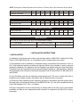
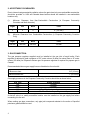
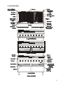
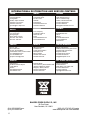
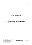
INSTALLATION AND OPERATING INSTRUCTIONS
Dante
SERIES
GAS CHAR BROILERS
Models: FL, CT and LC
INTENDED FOR OTHER THAN HOUSEHOLD USE
RETAIN THIS MANUAL FOR FUTURE REFERENCE
BROILER MUST BE KEPT CLEAR OF COMBUSTIBLES AT ALL TIMES
IMPORTANT INSTRUCTIONS
After the gas supply has been connected to your unit, it is extremely important to check piping for
possible leaks. To do this, use soap and water solution or solutions which are expressly made for
this purpose. DO NOT USE matches, candles, flames, or other sources of ignition since these
methods are extremely dangerous.
Post in a prominent location instructions to be followed in the event you smell gas. Obtain these
instructions from your local gas supplier.
FOR YOUR SAFETY
!
Do not store or use gasoline or other flammable vapors
and liquids in the vicinity of this or any other appliance.
WARNING
!
Improper installation, adjustment, alteration, service or maintenance
can cause property damage, injury or death. Read the Installation,
Operating and Maintenance Instructions thoroughly before installing or
servicing this equipment.
DE
CE
!
!
SI G N
R T IFI ED
4/01 Form # U4159A
Bakers Pride Oven Co., Inc.
30 Pine Street
New Rochelle, NY 10801
(914) 576-0200 Phone
(914) 576-0605 Fax
(800) 431-2745 US & Canada
www.bakerspride.com Web Address
1
INDEX
I. INSTALLATION INSTRUCTIONS
SECTION
1
2
3
4
5
6
7
8
9
10
11
12
ITEM
Installation
Clearances
Gas Connection
Burners, Heat Deflectors
Radiant Units
Glo-Stone Units
Drip Pans, Grease Drawer
Griddle Plate
Smoker Boxes
Lighting Instructions
Additional Instructions
Installation with Casters
PAGE
3
4
4
5
5
5
6
6
6
6
8
8
II. OPERATING INSTRUCTIONS
SECTION
1
2
ITEM
Lighting Procedure
Broiling
PAGE
8
8
III. MAINTENANCE
SECTION
ITEM
PAGE
1
Service
9
2
3
Care and Cleaning
Cleaning Tools
9
10
IV. INTERNATIONAL DISTRIBUTION & SERVICE CENTERS
SECTION
1
2
2
ITEM
Illustrations
International Distribution & Service Centers
PAGE
11
12
NOTE: Description of Model Numbers and Definition of Prefixes used in this manual are shown below.
(FL, CT, LC)B-XX(R, GS)
24
30
36
42
Number of Burners
3
4
5
6
48
7
54
60
66
72
8
9
10
11
Net Heat Input in kw (Europe)
G20 & G25 Gas
G30 & G31 Gas
17.58 23.45 29.31 35.17 41.03 46.89 52.75 58.61 64.47
15.82 21.11 26.38 31.65 36.93 42.20 47.48 52.75 58.03
Gross Heat Input in kw (Europe)
G20 & G25 Gas
G30 & G31 Gas
19.53 26.06 32.57 39.07 45.59 52.10 58.60 65.11 71.63
17.58 23.45 29.31 35.17 41.03 46.89 52.75 58.61 64.47
Model Definition
XX = 24, 30, 36, 42, 48, 54, 60, 66 or 72 (Overall width in inches)
FL = Floor Model
CT = Counter Top Model
LC = Low Profile Model
B = Broiler with Rear Gas Connection
R = Radiant Type
GS = Glo-Stone Type
I. INSTALLATION INSTRUCTIONS
1. INSTALLATION:
(i) Installation of this broiler must conform with the latest edition of ANSI Z223.1 National Fuel Gas
Code in USA (CAN/CGA-B-149.1 or 2 Installation Code in Canada) and/or local codes.
(ii) This appliance must be installed by a competent person in accordance with the rules in force. In
U.K. Corgi registered installers (Including the regions of British Gas) undertake to work to safe and
satisfactory standards. This appliance must be installed in accordance with the current Gas Safety
(Installation and Use) Regulations and the relevant Building Regulations / IEE Regulations. Detailed
recommendations are contained in the British Standards Code of Practice BS 6172, BS 5440:Part 2
and BS 6891.
(iii) Use this Broiler only with an adequately sized exhaust hood. The room in which this broiler is
installed must be suitably vented in accordance with the National and/or local codes.
(iv)This broiler when installed must be electrically grounded in accordance with local codes, and/or
the latest edition of the National Electrical Code ANSI/NFPA No. 70 in the USA (Canadian Electrical
Code CSA Standard C22.1, Part 1 in Canada).
In Europe, the appliance must be connected by an earthing cable to all other units in the complete
installation and thence to an independent earth connection in compliance with EN 60335-1 and/or
local codes.
3
2. ACCEPTABLE CLEARANCES:
Due to intense heat generated by radiation, above the grate level only non-combustible construction
should be provided. In USA and Canada these broilers should be installed in non-combustible
locations only.
(i)
Minimum Clearance from Non-Combustible Construction (in European Community
Countries and North America).
(ii)
Right
Left
Back
Floor
0
0
0
4" (100 mm)
Minimum Clearance from Combustible Construction (in European Community Countries
Only)
Right
Left
Back
Floor
250 mm
250 mm
250 mm
150 mm
3. GAS CONNECTION:
The gas pressure regulator supplied must be installed at the gas inlet of each broiler. Each
regulator is adjusted to yield a pressure of 3.5" water column (9 mbar) for natural Gas or 10" water
column (25 mbar) for Propane or Butane gas. No pressure regulator is required for propane gas in
Canada.
Recommended minimum gas supply lines are listed below for units with:
7 Burners or less:
3/4" (19 mm)
8 Burners and more:
1" (25.4 mm)
Gas supply pressures in the European Community Countries should be as shown below:
Gas Type
G20
G25
G20/25
G30
G31
Supply Pressure
20 mbar
25 mbar
20/25 mbar
30 or 50 mbar depending on country
30, 37 or 50 mbar depending on country
A shut-off valve in a readily accessible location must be installed on the gas supply line before
connecting it to the unit.
When making gas pipe connections, only pipe joint compound resistant to the action of liquefied
petroleum gases should be used.
4
The broiler and its individual manual shut-off valve must be physically disconnected from the gas
supply piping system during any pressure testing of that system at test pressure in excess of ½ psig
(3.45 kpa).
The broiler must be isolated from the gas supply piping system by closing its individual manual
shut-off valve during any pressure testing of the gas supply piping system at test pressures equal to
or less than ½ psig (3.45 kpa).
4. BURNERS, HEAT DEFLECTORS:
Air-Mixer caps on the front of all burners are adjusted, tightened and sealed before the unit leaves
the factory. If it is necessary to adjust the Air-Mixer caps, the adjustment must be done by a Factory
Authorized technician only, who should seal the adjustment screw after the adjustment.
(i) Position the slot on the front end of the burner over the pin on the front support, keeping the rear
end slightly raised up.
(ii) Place the front venturi end of the burner into valve assembly by fitting the center hole of the AirMixer cap over the brass orifice.
(iii) Drop the rear end of the burner over the pin on the burner support in the rear of the chamber.
(iv) Mount the ‘A’ shaped Heat Deflectors between the burners, supporting them on the locating
slots in the front and rear burner supports.
5. RADIANT UNITS:
(i) Mount ‘A’ shaped radiants over the burners with each end mounted on supports on the front and
rear of the chamber. One radiant should be mounted over each burner assembly.
(ii) Place the top grates, wider flange toward the back, over the radiants until the whole broiling area
is covered. Flipping Top Grates upside down and choosing between two supports in the rear, four
positions are possible for different slopes desired.
6. GLO-STONE UNITS:
(i) Mount angular bottom grate supports over the burners with each end mounted on
supports located on the front and rear of the chamber. One bottom grate support should be
mounted over each burner (small pilot shield towards the front).
(ii) Place the Stainless Steel expanded metal Bottom Grate(s) on the angular support above the
Burners.
(iii) Spread one layer of Glo-Stones covering all of the Bottom Grate(s).
!
IMPORTANT NOTES
Do not use more than one layer of glo-stones, as that will
reduce the amount of heat reaching the top grates and can
cause overheating and permanent damage to the unit.
!
5
(iv) Place Top Grates, wider flange toward the back, over the Glo-Stones until the whole broiling
area is covered. Flipping Top Grates upside down and choosing between two supports in the rear,
four positions are possible for different slopes desired.
7. DRIP PANS, GREASE DRAWER:
(i) Depending on the size of the unit, one or more Drip Pans are provided to hold any grease that
drips down while broiling. Water is usually added to the Drip Pans to reduce flare-ups and flashback.
(ii) A Grease Drawer is provided at the left of the Drip Pan to collect the grease from the grease
drain above.
(iii) One Grease Deflector is provided to prevent burning matter from falling into the Grease Drawer
and igniting the accumulated grease there. To install the Grease Deflector, clip its bottom edge to
the left side of the Drip Pan next to the Grease Drawer, push down all the way, then slide the Drip
Pan back into place.
(iv) Grease Drawer, Grease Deflector and Drip Pans should be cleaned daily or more frequently if
necessary.
8. GRIDDLE PLATE (Optional):
The Griddle plate should not cover more than 50% of the broiling area. The Griddle Plate should be
placed on top of the top grates, which for this purpose should be in the flat position.
9. SMOKER BOX (Optional):
(i) This consists of a Smoker Box Housing and a Wood Chip Drawer. For this option you will not
need the Heat Deflectors and the locating slots thus vacated are used to position the Smoker
Boxes.
(ii) From above, mount the Smoker Box Housing between the burners, supporting it on the locating
slots in the front and rear burner supports. From below in the front, slide the Wood Chip Drawer into
the Housing.
10. LIGHTING INSTRUCTIONS:
Each burner has a standing pilot burner which must be lit before the burners can be lit. To light the
Pilot Burners for:
(a) UNITS WITHOUT SAFETY PILOTS
(Not available for European Community Countries).
(i) Turn all broiler valves to ‘OFF’ position.
(ii) Open main gas shut-off valve(supplied by the customer).
(iii) Allow air to bleed from the gas line through the Pilot Burners.
(iv) Light each Pilot Burner using a lit taper.
6
Adjustment screws for the Pilot Valves are sealed at the factory after adjustment to provide a ½" (13
mm) flame. If adjustment is required, it should be done by a factory authorized technician only, and
the screws must be sealed after the adjustment.
(v) Turn the burner control valves to ‘ON’ to light the burners.
If any burner fails to light, turn that burner valve to ‘OFF’, wait five minutes then repeat the above
procedure.
(vi) After all burners have been lit, turn all burner valves ‘OFF’ and make sure that the pilot burners
stay lit.
Each burner may now be adjusted to the desired flame size by turning the individual burner valve
handle.
TO SHUT DOWN THE UNIT, TURN ALL VALVES ‘OFF’. WAIT FIVE MINUTES BEFORE
ATTEMPTING TO RE-LIGHT.
NOTE: The Pilot Burners will stay lit until the Gas Supply to the unit is turned ‘OFF’.
(b) UNITS WITH SAFETY PILOTS
(i) Turn all broiler valves to ‘O’ position.
(ii) Open main gas shut-off valve (supplied by the customer).
(iii) For each burner, press, turn counter clockwise and hold down that burner control knob at the
pilot burner ignition position.
(iv) Using a lit taper, light that pilot burner.
(v) Release the knob after 30 seconds. Pilot burner should stay lit.
IF THE PILOT BURNER DOES NOT STAY LIT, WAIT FIVE MINUTES AND REPEAT STEPS (iii)
AND (iv). THIS TIME HOLD DOWN THE KNOB LONGER BEFORE RELEASING.
Adjustment screws for the Pilot Burner are sealed at the factory after adjustment to provide a ½" (13
mm) flame. If adjustment is required, it should be done by a Factory Authorized technician only, and
the screws must be sealed after the adjustment.
Each burner may now be adjusted to the desired flame size by turning the individual burner valve
knob
TO SHUT DOWN A BURNER, TURN THAT CONTROL KNOB CLOCKWISE TO THE PILOT
BURNER IGNITION POSITION.
TO SHUT DOWN THE PILOT BURNER AS WELL, PRESS THAT CONTROL KNOB AND TURN
CLOCKWISE TO THE ‘O’ POSITION.
WAIT FIVE MINUTES BEFORE ATTEMPTING TO RE-LIGHT.
7
11. ADDITIONAL INSTRUCTIONS:
(i) Keep the area around the broiler free and clear of all combustible material.
(ii) Provision of adequate air supply to your broiler is essential. Provide for sufficient outside air to
enter the broiling area and assure that this air flow is not obstructed.
(iii) Air enters the burner area from the front of your broiler only. Assure that this area is kept open
and unobstructed.
(iv) Servicing is accomplished through the front and top of the broiler. Assure that this area is kept
unobstructed for proper servicing and operation.
12. INSTALLATION WITH CASTERS:
THIS IS AVAILABLE FOR FLOOR MODELS ONLY.
Four casters (two with wheel brakes) and the mounting hardware are packed and included in the
shipment, if ordered that way.
Install casters with wheel brakes on the front of the unit.
Installation of the unit should be made with a connector that complies with the latest edition of the
Standard for Connectors for Movable Gas Appliances ANSI Z21.69, in the USA (CAN CGA-6.16 in
Canada) and a quick disconnect device that complies with the latest edition of the standard for
quick disconnect devices for use with gas fuel ANSI Z21.41 in the USA (CAN 1-6.7 in Canada.)
Adequate means must be provided to limit the movement of the appliance without depending on the
connector and any quick disconnect device or its associated piping to limit the appliance movement.
The restraint should be attached to the right side of the back of the unit close to the gas inlet pipe.
If disconnection of the restraint is necessary, the supply gas line should be disconnected first, then
the restraint. When returning it to its position, the restraint should be reconnected first, before the
gas line is reconnected.
II. OPERATING INSTRUCTIONS
ONLY QUALIFIED PERSONNEL, PROPERLY TRAINED AND FAMILIAR WITH THIS
EQUIPMENT SHOULD OPERATE THIS BROILER.
1. LIGHTING INSTRUCTIONS:
See Section 10 of Installation Instructions.
Once the Pilot Burners are lit, the Main Burners of the broiler may be turned ON or OFF by
turning the control knobs.
2. BROILING:
BROILER TOP GRATES MUST BE HOT ENOUGH TO MAKE BLACK CHAR MARKS WHEN
STARTING TO BROIL.
Adequate preheating time is necessary for the food to cook properly and to release from the broiler
grates. Before Broiling, allow Radiant type units to preheat for 10-15 minutes and Glo-Stone type
units for 20-25 minutes.
8
(i) Do not press the juice out of the meat as that will dry the meat.
(ii) After Broiling, allow the meat to sit covered on a heated platter for 2-5 minutes before cutting.
This will allow the juices to ‘settle’ and the meat will be more moist.
(iii) Do not use forks or other sharp objects to poke holes in the meat or to cut the meat as it cooks.
(iv) Thick pieces of meat require longer broiling time with less flare-up. Reduce flare-up by trimming
excess fat for a longer broil time without burning.
(v) Keep the unit clean. Food caught in the grates will not allow hot air to rise around the product.
This will result in uneven heating, increase the cooking time and cause overheating of the Broiler
which may result in permanent damage.
III. MAINTENANCE
1. SERVICE:
ALL SERVICING SHOULD BE PERFORMED BY A FACTORY AUTHORIZED TECHNICIAN
ONLY.
Shut off the main gas supply before attempting any maintenance or service on the unit. If required,
contact your dealer, a local service company or the factory to obtain a qualified technician for the
required maintenance/service. A list of Dealer and Service locations is part of this manual.
2. CARE AND CLEANING:
(A) FOR ALL MODELS.
The ventilation system must be inspected every six months, more frequently if necessary, and
maintained clean and free of obstruction.
(i) TOP GRATES: The top grates should be cleaned daily with a stiff wire brush or steel wool. The
rods specially the underside need only to be scraped clean of all accumulated food and fat. A light
coat of oil should be applied to the rods after cleaning.
(ii) OUTER SIDES AND THE FRONT: These are stainless steel surfaces. Stainless Steel Cleaner
or any similar cleaner can be used.
(iii) INNER COOKING AREA: These are stainless steel surfaces. Make sure that all the residue is
removed before cooking is resumed.
(iv) HEAT DEFLECTORS: These should be removed and cleaned frequently. These are stainless
steel surfaces. Stainless Steel Cleaner or any similar cleaner can be used.
(v) SMOKER BOXES: The Wood Chip Drawer should be removed and cleaned every day or more
frequently if necessary.
Smoker Box Housing should be removed and cleaned frequently so that drippings do not
accumulate.
9
(vi) INNER PANELS: These are made of Aluminized steel. Use hot soapy water and soft nylon
scrub pads to clean the surfaces.
(vii) DRIP PAN: Drip Pan and the Grease Drawer should be cleaned daily or more often if
necessary.
(B) FOR RADIANT MODELS.
RADIANTS: These should be removed and cleaned frequently. These are stainless steel surfaces.
Stainless Steel Cleaner or any similar cleaner can be used.
(C) FOR GLO-STONE MODELS:
(i) CARE OF GLO-STONES: On a weekly basis, the top grates should be removed and the GloStones mixed about to break away any carbon deposit so that it falls through the bottom grates.
Spread the Glo-Stones evenly and add only the amount necessary for a single layer.
(ii) CARE OF BOTTOM GRATES: Periodically push all the Glo-Stones to one side and inspect the
bottom grates. If necessary brush the grates with a wire brush.
(iii) BOTTOM GRATE SUPPORT: Frequently clean the Bottom Grate Support with a stiff wire
brush.
CAUTION
!
Clean the unit only when it is cold.
When cleaning, be sure to rub the metal along grains.
Do not use abrasive pads for cleaning.
Do not use caustic cleaning compounds on aluminized surfaces.
!
3. CLEANING TOOLS:
Several models of specially designed top grate brushes and grease drain scrapers are available
from Bakers Pride. Contact your local dealer or Bakers Pride for more information.
10
4. ILLUSTRATIONS:
11
INTERNATIONAL DISTRIBUTION AND SERVICE CENTERS
JAPAN
ISRAEL
CANADA
Proserv
3-2-26 Tsukamoto
Yodogawaku
Osaka, Japan 532-0026
816-6307-7471 Phone
816-6307-9181 Fax
[email protected]
Joram Baron Agencies
14 Shenkar Street
P.O. Box 3147
Herzalia
Israel 46130
972-9-9551030 Phone
9723-921-6690 Fax
Rabco
4500 Sheppard Ave. E.
Unit 9-11 Scarborough
Ontario, Canada M1S 3R6
416-321-5823 Phone
416-321-5826 Fax
[email protected]
NORWAY
KOREA
Shinkang Corporation
16-4, Seongsoo
Seongdong-ku
Seoul, Korea 133110
82-2-461-1637 Phone
82-2-461-1639 Fax
N & J Company
21 Mikveh Israel St.
65115 Tel Aviv
Israel
972-3-5602693 Phone
972-3-5662816 Fax
Einar Riise & Son
Enebakkveien 64C
Oslo 6
Norway
47-2-208-3300 Phone
47-2-2190680 Fax
www.riise.no
FRANCE
MEXICO
UNITED KINGDOM
S.C.A.L. SA.
Za Courtaboeuf 1
20, Ave. De la Baltique
Courtaboeuf Cedex, France 91958
33-1-69828585 Phone
33-1-69-828599 Fax
[email protected]
ABC Proveedores
Cantaritos #3
Lomas Tecamachalco
Naucalpan, Edo.
Mexico 53950
525-589-1597 Phone
525-589-2205 Fax
Bakers Pride Europe
Wealden Estate Farningham Road
Crowborough, East Sussex
England TN6 2JR
441-892-667311 Phone
441-892-667322 Fax
[email protected]
ALL OTHER COUNTRIES
GREECE
Heinami S.A.
87 Alimou Avenue-Airport
17455 Alimos
Greece
301-9966040 Phone
301-9966047 Fax
Fastfood Equip
Juan Palomar y Arias Number 83-B
Jardines Vallarta CP 45020
Zapopan, Jallisco, Mexico
523-673-5786 Phone
523-673-2943 Fax
Dorian International
2 Gannett Drive
White Plains, NY 10604 USA
914-697-9800 Phone
914-697-9190 Fax
[email protected]
BAKERS PRIDE OVEN CO., INC.
30 Pine Street
New Rochelle, NY 10801
(914) 576-0200 Phone
(914) 576-0605 Fax
12
(800) 431-2745 US & Canada
www.bakerspride.com Web Address