1
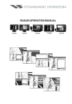
IMITRE
Issue 2 10/05/2000
Mitre Amplifiers
Operating Instructions
Baldwin Boxall Communications Ltd.
Wealden Industrial Estate, Farningham Road
Crowborough, East Sussex, TN6 2JR
Telephone: 01892 664422 Fax: 01892 663146
Website: www.baldwinboxall.co.uk
Email: [email protected]
C O M M U N I C A T I O N S
MITRE DESCRIPTION AND SPECIFICATIONS
The Mitre range of amplifiers consists of integrated slave and tuner/amplifier models. They are
designed to give a high degree of flexibility as well as quality and reliability.
Integrated Amplifiers M2000M (Mixer) M2060M (60 Watt), M2120M (120 Watt), M2300M (300
Watt)
1. Four balanced microphone/line universal inputs.
2. Each universal input has the option of cascade priority, phantom power, chime and volume
restoration/busy, XLR or screw terminations.
3. Built-in one, two or three note chime with pre-set volume control.
4. Built-in alarm tone generator with pre-set volume control. Tones are adjustable. A continuous
900 Hz- tone or continuous pips can also be configured making it suitable for class change, start
and stop work, etc.
5. Each universal input has input live indicator.
6. Master volume, treble and bass controls.
7. 300 Watt version M2300M has four zone relay selector as standard.
NB: As supplied from the factory all zoned outputs are energised.
8. Internal option socket. Can be used to add frequency equaliser etc.
9. Music mute facility, which allows for music to be totally muted or ‘ducked’ to a pre-set level,
when paging operated.
10. Remote music mute DC input from time clocks etc.
11. Output stage protected by thermal shut down in event of unsuitable load.
12. Auxiliary stereo music input (internally mixed) to accept tuners, CD players or tape decks.
13. Power amplifier input phono connector to enable 2 amplifiers to be connected together to provide
10 inputs.
14. 24V DC output.
15. M2000M Mixer version has two 0dB balanced line level outputs to feed separate amplifiers.
Slave Amplifiers M2120S (120 Watt), M2300S (300 Watt)
1. Each amplifier has two balanced line inputs which have selectable priority and rear mounted
independent gain controls.
2. Priority selectable by DIL switch.
3. Internal option socket. Can be used to add frequency equalisers, etc.
4. Output level indicator.
5. Output stage protected by thermal shut down in event of unsuitable load.
6. 30V 1.5A output for powering mixers, etc.
Tuner Amplifiers M2060A (60 Watt), M2120A (120 Watt), M2300A (300 Watt)
1. These have the same facilities as the mixer amplifiers with the added facilities of an FM/AM
tuner.
2. The FM Tuner operates between 87-108 MHz and the AM between 525-1605 kHz.
3. Phase locked loop tuner with digital display of frequency and selected channel providing 7 FM, 7
AM and an auxiliary input for CD or tape.
-2Issue 2
SAFETY
IMPORTANT NOTES - DO’S AND DON’TS
Ventilation
Always ensure adequate ventilation to the amplifier especially the 300 Watt version. Do not obstruct
ventilation holes in cover or base. The 300 Watt versions include internal fans that are temperature
controlled to prevent overheating, especially if the amplifiers are rack mounted and used for
continuous broadcast of music material. Should the amplifier exceed its safe operating temperature it
will automatically reduce its volume to a safe level thus allowing it to cool. Once cooled it will
operate normally without manual resetting.
AC Power Input - Danger High Voltage
Only connect to an AC 50-60 Hz 230V supply using the lead assembly supplied or an equivalent type
with a suitable IEC connector.
Always ensure that the amplifier is earthed.
Always unplug the power before removing the top cover.
100V Loudspeaker Output - Danger High Voltage
Ensure that the loudspeaker connections are suitably protected and cannot be touched. Always replace
output plug insulated covers.
Always ensure that the total speaker load does not exceed the rating of the amplifier used. If unsure
use an impedance meter to measure the unknown load. Using a multimeter selected to the resistance
range ensure that the speaker line is not connected to earth.
NB: As supplied from the factory a jumper lead is included on the rear of the M2300. This lead
energises the four output relays and enables the user to connect to any of the four zoned outputs.
Moisture
Do not allow water to come in contact with the amplifier and its external connections.
Cable Types
Always ensure that the correct cable type is used for the signal level.
A twin screened cable should be used for balanced inputs operating at mic or line level. Zone
selection and access control cables do not generally require screening and should not share the same
screen as the balanced input.
Loudspeaker output cables should be rated in excess of 100V and the cross sectional area to suit the
load without excessive power loss. Always ensure that output cables are kept as far away from input
cables as possible reducing the risk of instability.
Fuses
Always replace using the correct rating and type to ensure safe operation.
-3Issue 2
Mitre Integrated Technical Specification
Rated output power
100V line 230V AC supply
MIXER
60
120
300
N/A
60W 166 Ohms
120W 83 Ohms
300W 33 Ohms
THD 1 kHz rated output
Aux input 230V AC supply
Less than 0.5% typically 0.2%
Typical output power 1% THD
Aux input 230V AC supply
N/A
Output regulation
(1 kHz 100V line)
N/A
Output voltages obtainable
(Pin selection)
N/A
80W 125 Ohms
Fuse protection
1 x AC supply 20 x 5 mm
2 x DC (amplifier) auto blade type
50 & 100V
230V 50-60 Hz
20VA
N/A
12VA
150VA
18VA
300VA
26VA
700VA
630mA(T)
1x1A(F)
1x5A(F)
2A(T)
5A(F)
3.15A(T)
10A(F)
6.3A(T)
20A(F)
1 x DC Aux output
Self Resettable Fuse
Aux input phono stereo summed mono
Sensitivity
Frequency response -3 dB @
Signal to noise ratio
100mV @ 20k Ohms
40 Hz - 20 kHz
Better than 80 dB
Tone controls
Bass
Treble
± 12 dB @ 100 Hz
± 12 dB @ 12 kHz
Universal input (line)
Sensitivity
Frequency response -3 dB @
Signal to noise ratio
80mV @ 12K balanced
40 Hz - 18 kHz
Better than 70 dB
Universal input (Mic)
Sensitivity
600 µV balanced
Input impedance
Without phantom power
With phantom power 15V
12k Ohms
660 Ohms
Frequency response -3dB @
40 Hz - 18 kHz
Common mode rejection ratio
50 Hz - 30 kHz
Better than 60 dB
Signal to noise ratio terminated 200 Ohms
Better than 60 dB
System busy output
Open collector 0.5A @ 40V total max.
Aux line output level
Source impedance
0 dBm transformer isolated
100 Ohms
Power amplifier input
Sensitivity
Impedance
800mV
15K Ohms
Busy/restoration relay output
2 pole change-over 5A @ 100V max.
DC Aux output
4-zone relay output
30V @ 1.5A max.
N/A
LED indicators x 5
N/A
N/A
5A @100V max.
1 per universal input (indicates busy state) 1 indicates presence of 24V Aux
supply
Terminations
AC supply input
Power amp input
Aux signal input
Universal input
Alarm trigger & 0dB line output
Busy/restoration relay output
Loudspeaker line output
3-pin, DIN IEC 6A
1 x phono
2 x phono, Stereo summed mono
6-pin, Screw terminated connector + 3-pin XLR
6-pin, Screw terminated connector
8-pin, Screw terminated connector
3-pin, Screw terminated connector
Dimensions (cm) (D x W x H)
Weight
340W 29 Ohms
Better than 1dB
Supply voltage AC
Power consumption @ 230V
Quiescent (no external DC load)
Rated output power @ 1 kHz
150W 66 Ohms
340 x 430 x 90
7.1 Kg
11.2 Kg
340 x 430 x 132
12 Kg
18 Kg
-4Issue 2
Mitre Tuner Specification
FM tuning range
87-108 MHz
Sensitivity for 40 dB signal to noise ratio
(ref. to ±22.5 kHz)
20 dBµ typical
IF frequency
10.7 MHz
IF rejection @ 98 MHz
70 dB typical
Image rejection @ 98 MHz
80 dB typical
AM rejection @ 98 MHz
70 dB typical
Antenna input impedance
75 Ohms unbalanced
AM tuning range
525-1605 kHz
Sensitivity for 30 dB signal to noise ratio
(ref. to 30% modulation)
40 dBµ typical
IF frequency
450 kHz
IF rejection @ 1050 kHz
55 dB typical
Image rejection @ 1050 kHz
36 dB typical
AGC @ 1050 kHz
60 dB typical
Antenna input impedance
To suit loop antenna
Pre-set channel selection
7 FM
Tuned frequency indicator
4
7 segment LED displays
Channel indicator
1
7 segment LED displays
Memory battery back-up
90 days
7 AM
1 Aux
-5Issue 2
-6-
Issue 2
MOUNTED ON
PC1180
2 3
3 2
1 1
600uV MIC
80mV LINE
INPUT 4
UNIVERSAL
MOUNTED ON
PC1180
2 3
3 2
1 1
600uV MIC
80mV LINE
INPUT 3
UNIVERSAL
MOUNTED ON
PC1180
2 3
3 2
1 1
600uV MIC
80mV LINE
INPUT 2
UNIVERSAL
MOUNTED ON
PC1180
2 3
3 2
1 1
600uV MIC
80mV LINE
INPUT 1
UNIVERSAL
2
3
4
I/P
0V
ACCESS
1
2
3
4
I/P
0V
ACCESS
6
+24V
4
ACCESS
6
+24V
2
3
4
I/P
0V
ACCESS
6
+24V
6
INPUT 5
PHONO INPUT
100mV
3
2
1
5
BUSY
0V
1
I/P
3
2
1
5
BUSY
0V
2
3
0V
1
I/P
I/P
3
2
1
5
BUSY
0V
1
I/P
3
2
1
6
+24V
5
5
BUSY
0V
1
I/P
4
2
3
0V
0V
0V
0V
0V
R
L
CHIME
0V
0V
+15V
+15V
+15V
SELECT
1,2 0R 3 NOTE
330R
X2
PHANTOM
POWER
330R
X2
PHANTOM
POWER
0V
+15V
330R
X2
PHANTOM
POWER
330R
X2
PHANTOM
POWER
REAR
PRESET
MUSIC
MUTE
PRESET
INPUT 5
VOLUME
MIC/LINE
MIC/LINE
MIC/LINE
0V
ALARM
SIREN
MIC/LINE
0V
INPUT 4
VOLUME
0V
INPUT 3
VOLUME
0V
INPUT 2
VOLUME
0V
INPUT 1
VOLUME
0V
REAR
PRESET
AUX
MUTE
+15V
PRIORITY 6
PRIORITY 5
CHIME
REST
PRI
PRIORITY 4
CHIME
REST
PRI
PRIORITY 3
CHIME
REST
PRI
PRIORITY 2
PRIORITY 1
CHIME
REST
PRI
PRIORITY CIRCUIT
+24V
+24V
+24V
+24V
0V
INPUT
ACTIVE
INPUT
ACTIVE
INPUT
ACTIVE
INPUT
ACTIVE
VIRTUAL EARTH
MIXER
0V
BASS
ONLY FITTED TO
300W VERSIONS
PC1171
MASTER
VOLUME
60,120 & 300W
LINK
-VE
0V
+VE
TREBLE
12K
OPTION
PSU
SWITCH ON TO
SELECT MUSIC
OUT
0V
+VE
IN
MIXER LINK
POST
PRE
4
3K3
RL4
2
0V
+24V
RL3
MAINS
SWITCH
3
1
2
3
RL2
POWER
AMPLIFIER
60,120 OR 300W
0V
MAINS
FUSE
SUPPLY
PRESENT
2A RESETTABLE
0V
L
E
1
3
4
5
6
7
+24V
0V
NOT FITTED TO
300W VERSIONS
LINE ZONE 4
LINE ZONE 3
LINE ZONE 2
LINE ZONE 1
220V - 240V
AC 50Hz - 60Hz
5A @ 100V
BUSY/VOLUME
RESTORATION
+24V
8
ALL 2
1
4
2
3
2
N
1
3
4
2
ALL 1
GROUP
0V
50V
100V
0V
50V
100V
0V
50V
100V
0V
50V
100V
0V
50V
100V
800mV
POWER AMP INPUT
AUX MUTE
RELAY COIL
ALARM ACCESS
6
5
0dB OUTPUT
FITTED TO
MIXER ONLY
0dB OUTPUT
7
8
6
5
4
3
2
1
+24V
RL1
0V
0V
1
3
2
1
3
2
0V
1
MOUNTED ON
PC1180
1
2
3
Mitre Slave
120W 300W
The Mitre Slave is equipped with two 0dBM balanced line inputs incorporating a priority switching
system. The priority is selected using a two-way dual in line switch. Switch ‘1’ when selected ‘on’
provides input 2 muting when 1 is accessed. Switch ‘2’ when selected ‘off’ enables the first input
irrespective of access conditions. When both switches are selected ‘on’ input 1 will override input 2.
Therefore it is possible to have both inputs mixing together or cascade priority depending on the
requirements, refer to rear panel drawing.
LED indicators on the front panel show clearly which input or inputs are busy and the channel gain
may be individually set using the rear panel controls. The output stage is protected against overload
conditions, i.e. short circuits etc., by means of sensing the current and voltage and presenting this error
signal to a drive limiter circuit. Should the amplifier be subjected to an abnormal load the input to the
power amplifier is limited to a safe level.
Over temperature protection is provided using sensors attached to the output stage heatsink. Should
the temperature exceed 90°C the input signal is reduced to a low level preventing permanent damage
to the amplifier. When the amplifier cools down, it will perform as normal without manual resetting.
For added reliability the 300 Watt version includes internal fans that will operate if the heatsink
temperature exceeds 70°C.
The inputs to the amplifier are presented on two separate four-way plug-in screw terminal connectors,
each connector provides a balanced audio input, ground and access DC control input. The output is
presented on a three-way plug/screw termination connector providing 50V or 100V output.
The front panel LED indicators include an output level status indicator consisting of four LED’s
indicating 5V, 25V, 50V and 100V maximum output level.
-7Issue 2
Mitre Slave Technical Specification
Rated output power
100V line 230V AC supply
120W
300W
120W 83 Ohms
300W 33 Ohms
THD 1 kHz rated output
230V AC supply
Typical output power 1% THD
230V AC supply
Less than 0.5% typically 0.2%
150W 66 Ohms
Output regulation
1 kHz 100V line
360W 29 Ohms
Better than 1 dB
Output voltages obtainable by pin selection
50 & 100V
Supply voltage AC
230V 50-60 Hz
Power consumption
Quiescent
Rated output power @ 1 kHz
Fuse protection
1 x AC supply 20 x 5 mm
2 x DC (amplifier) auto blade type
1 x DC Aux output 20 x 5 mm
Input type
18VA
300VA
26VA
700VA
3.15A(T)
10A(F)
2A(T)
6.3A(T)
20A(F)
2A(T)
2 x line balanced with priority gating
Input sensitivity
0.5V @ 40K Ohms balanced
Input common mode rejection ratio
50 Hz - 30 kHz
Frequency response -3dB @
Signal to noise ratio
Selectable high pass filter
Better than 40 dB typically 60 dB
40 Hz - 20 kHz
Better than 85 dB
200 Hz 12 dB/octave
DC Aux output
30V @ 1.5A max.
LED indicators
Output level indicator 5V 25V 50V 100V
Inputs busy, i.e. accessed
Terminations
AC supply input
Line signal inputs
DC Aux output
Loudspeaker line output
Dimensions (cm) (D x W x H)
3-pin
4-pin
2-pin
3-pin
DIN IEC 6A
Screw terminated connector
Crimp terminated connector
Screw terminated connector
340 x 430 x 90
340 x 430 x 132
11.5 Kg
17.5 Kg
Weight
-8Issue 2
-9-
Issue 2
INPUT 2
BALANCED
INPUT 500mV
INPUT 1
BALANCED
INPUT 500mV
3
0V
3
0V
4
2
I/P
ACCESS
1
I/P
4
2
I/P
ACCESS
1
I/P
0V
0V
+
-
+
-
0V
INPUT 2
VOLUME
24V AUX SUPPLY
OUTPUT 1.5A MAX
PRIORITY
LOGIC
0V
INPUT 1
VOLUME
-VE
+VE
-30V
0V
+30V
2A
200Hz HIGH
PASS FILTER
LK1
REMOVE LINK TO
ENABLE FILTER
PSU
0V
+VE
OUT
IN
MAINS
SWITCH
OPTION
SOCKET
OUTPUT
LEVEL
INDICATOR
5V
25V
50V
100V
POWER
AMPLIFIER
120 OR 300W
MAINS
FUSE
L
N
E
230V AC
50Hz-60Hz
0V
50V
100V
MITRE INTEGRATED AMPLIFIER FEATURES
Universal Inputs.
Each of the universal inputs has a 6 way DIL switch to select the required facilities as shown below :
Note: Each universal input has to be accessed (by linking pins 3 and 4) in order to make the input live.
The green LED on the front panel illuminates when an input has been accessed.
Priority Selection
If priority is set to ‘ON’ then the input will override descending inputs.
The hierarchy in descending order is as follows:
Input 1 – Overall Priority
Alarm Tone
Input 2
Input 3
Input 4
Music / Aux – No Priority
CHIME
ON = CHIME WILL SOUND
WHEN INPUT IS ACCESSED
OFF = NO CHIME
VOLUME RESTORATION/BUSY
ON = VOL REST RELAY & BUSY
OUTPUTS OPERATE WHEN INPUT
ACCESSED
OFF = VOL REST RELAY & BUSY
OUTPUTS WILL NOT OPERATE
WHEN INPUT ACCESSED
SENSITIVITY
ON = MIC 0.6mV.
OFF = LINE 80mV.
PHANTOM POWER
PRIORITY
ON = THIS INPUT WILL
OVERRIDE DESCENDING INPUTS
OFF = THIS INPUT WILL NOT
OVERRIDE DESCENDING INPUTS
AND WILL MIX
BOTH ON = 15V MIC PHANTOM POWER
BOTH OFF = NO PHANTOM POWER
ON
1 2 3 4 5 6
ACCESS CLOSE TO 0V TO ACCESS INPUT.
BUSY OPEN COLLECTOR OUTPUT 40V @ 0.5A MAX
CLOSES TO 0V WHEN ACTIVE. SEE SWITCH 2 ABOVE.
0V (GROUND)
BALANCED SIGNAL INPUT
SEE SWITCH 4 ABOVE
+24V TO FEED MICROPHONE PRE-AMP,
BUSY INDICATORS ETC.
1
2
3
4
5
6
INPUT
CONNECTOR
BUSY
INDICATOR
PRESS TO
SPEAK SWITCH
- 10 Issue 2
Volume Restoration Relay.
This relay will energise whenever an input is accessed if the “Vol. Rest / Busy” switch (2) has been
selected.
The relay contacts can switch either an AC or DC signal providing it does not exceed 100V @ 5A.
Here are 3 examples :
VOLUME
CONTROL
100V
AMPLIFIER
OUTPUT
50V
0V
Example 1: 3 Wire System to Override a Remote Auto Transformer Volume Control.
+24V
SYSTEM BUSY
INDICATOR
0V
Example 2: Aux. Busy Indicator.
100V
PAGING ONLY
(OFFICES)
50V
0V
MUSIC & PAGING
(WORKSHOP)
Example 3: Paging Only Output.
- 11 Issue 2
FLOATING LINE OUTPUT
SWITCH
1
2
AFTER MASTER
& TONE CONTROLS
BEFORE MASTER
& TONE CONTROLS
CHIME SELECTION
SWITCH
3
4
ON
OFF
NO CHIME
OFF
OFF
ON
1 NOTE CHIME
OFF
ON
2 NOTE CHIME
ON
OFF
3 NOTE CHIME
ON
ON
NOTE. DO NOT SELECT
BOTH SWITCHES TO ON
OFF
ON
MAX
CHIME VOLUME
1 2 3 4
MAX
ALARM TONE VOLUME
ALARM ACCESS, CLOSE
TO 0V TO ACCESS
ALARM TONE GENERATOR
0V (GROUND)
FLOATING LINE OUTPUT
RELAY COIL
0dB TRANSFORMER ISOLATED
OUTPUT TO FEED SLAVE
AMPLIFIER, TAPE RECORDERS ETC
SEE SWITCH 1&2
AUX MUTE
1
2
3
4
5
6
CONNECTOR
CLOSE TO 0V TO
MUTE AUX INPUT.
TIME SWITCH ETC
OUTPUT TO FEED
OTHER EQUIPMENT
CLOSE TO SOUND
ALARM TONE
Alarm, Chime and Aux. Line Output Connections.
Music Mute Control
The amplifier has an internal pre-set VR6 which controls the residual level of background music
during paging. For full muting VR6 should be turned fully clockwise. For partial muting VR6 should
be turned anti-clockwise to suit operational requirements. Once the priority microphone is deselected
the background music level will fade up gently to its original setting. The unit is supplied with muting
set to maximum.
MAX MUTE
VR6
MUSIC
MUTE
AUX VOLUME
CONTROL
PART VIEW OF PRINTED
BOARD CIRCUIT WITH
TOP COVER REMOVED
- 12 Issue 2
Alarm Tone Generator.
The Alarm Tone Generator is configured when dispatched from the factory to produce a 1 second
alternating 500 and 900 Hz Dee-Daa sound.
However, it is possible to produce pulsed or continuous single frequency tones which could be used
for start and stop work, class change, etc. Will remain sounding until access switch removed.
FACTORY
SET
900Hz
FACTORY
SET
500Hz
VR9
JP22
SET ALARM
C76 R105 D8 D9 R104
C64
VR10
TP4
R121
VR9
JP22
JUMPER
LINK
CONTINUOUS
900Hz
500Hz
TP4
CONTINUOUS
900Hz
500Hz
SET ALARM
VR10
R121
JUMPER
LINK
C76 R105 D8 D9 R104
C64
TR1
TR1
R103
R103
C77
C77
JP21
U6
JP21
C38
500Hz PIPS
U6
C38
500Hz PIPS
900Hz PIPS
900Hz PIPS
CONTINUOUS 900Hz TONE
VR9
JP22
SET ALARM
VR10
TP4
R121
VR9
JP22
C76 R105 D8 D9 R104
CONTINUOUS
500Hz
900Hz
TP4
CONTINUOUS
500Hz
900Hz
SET ALARM
VR10
R121
CONTINUOUS 500Hz TONE
C76 R105 D8 D9 R104
C64
C64
TR1
TR1
R103
C77
JP21
500Hz PIPS
R103
JUMPER
LINK
U6
C38
C77
JP21
500Hz PIPS
900Hz PIPS
U6
C38
900Hz PIPS
CONTINUOUS 900Hz PIPS
CONTINUOUS 500Hz PIPS
Part views of printed circuit board with top cover removed.
When the Alarm Tone Generator is accessed it will provide a “Busy” output to all universal inputs and
energise the Volume Restoration relay.
- 13 Issue 2
Mitre FM / AM Tuner Amplifier.
The tuner provides 7 x FM, 7 x AM (MW) and 1 x Aux. programme.
Front Panel View.
Rear Panel Time Switch Connections
FLOATING LINE
OUTPUT CONNECTOR
AUX MUTE
0V (GROUND)
1
2
3
4
5
6
STORE SWITCH
VIA FRO NT PANEL HOLE
CONNECTOR
up
frequency
AM=kH z
FM=MHz
programme
CLOSE TO 0V TO
MUTE AUX INPUT / TUNER.
USING TIME SWITCH ETC
am
fm
Connect the Time Switch between pin 6 and 0V
(pin 3) to mute the Tuner.
down
programme
Tuning a Channel.
Press the “Programme” switch until the channel you wish to tune is displayed by the Programme
indicator and the FM / AM indicators. The Frequency indicator will indicate the original setting.
By using the “UP” or “DOWN” switches step to the required frequency.
The Programme indicator will now pulse inviting you to store the new selection by pressing the
“Store” switch using a small screwdriver or similar tool through the front panel hole.
After storing, the Programme indicator will stop pulsing.
Press the “Programme” switch once and the Programme indicator will indicate the next programme.
To tune repeat the above until all channels have been set.
After 7 channels have been selected the Aux. input is selected. The Programme indicator displays an
“A”.
When installing this unit it is important to connect a suitable aerial.
A dipole or a multi-element directional antenna, mounted externally should give optimum FM
reception. For AM a loop, long whip or long wire aerial will suit.
Both FM and AM aerials should be wired using a coax type cable, and the cable kept to a minimum
length for best results.
Please note. An internal battery supports the memory of the tuner module. If the module fails to
operate correctly when first switched on then the battery voltage may have dropped too low to
maintain the memory. Once this has happened the tuner module must be reset before it can be
reprogrammed.
To reset the tuner the unit must be turned off and the “STORE” button held in whilst switching the
power back on. This will restore all pre-set stations to their default settings of 89.1MHz for FM
stations and 909KHz for AM stations.
- 14 Issue 2
VOL REST RELAY
5A 100V MAX
2A MAX
0V +24V
MANUFACTURED IN THE UK BY
BALDWIN BOXALL COMMUNICATIONS LTD.
CROWBOROUGH, E.SUSSEX. TN6 2JR
TEL 01892 664422
FAX 01892 663146
+24V DC O/P FUSE
SELF RESETTABLE
SUPPLY PRESENT
FM
AM/FM AERIAL
AM
PUSH
O/P 2
0V
1
0dBM
FLOATING
ALARM
LINE O/P 0V ACC
BALANCED 0dB OUTPUT 2
BAL
O/P
2
PUSH
O/P 1
1 2 34
1 2
3 NOTE CHIME
ON
POWER AMP I/P
RLY COIL
POST MASTER V/C
AUX
PRE MASTER V/C
MUTE
3
ALARM
VOLUME
R
AUX
INPUT
PRIORITY
0.6mV MIC
1 23 45 6
CHIME
V REST/BUSY
PUSH
PUSH
CHIME
VOLUME
INPUT3
INPUT4
L
BALANCED 0dB OUTPUT 1
MITRE MIXER
The Mitre Mixer has all of the features of the Mitre Integrated Amplifiers but instead of producing a
100V line output to drive speakers directly, the output is a 0dB balanced line output to drive other
amplifiers.
The output is presented on two paralleled XLR connectors.
- 15 -
Issue 2
Example Installations With Wiring Diagrams.
The following drawings show examples of how to connect amplifiers using the numerous facilities
included in them.
NB. As supplied from the factory a jumper lead is included on the rear of the M2300. This lead
energises the four output relays and enables the user to connect to any of the four zoned outputs. If
any output zones are not required the relevant ‘Group Select’ DIL switch should be set to ‘OFF’.
FIGURE 1 (Page 18) - 3 Zone : Music only, Paging only, and Music and Paging.
This example shows the recommended method of obtaining the amplifier output i.e. Music and Paging, and
also provides two switched outputs for Music only and Paging only.
The Paging only output is useful for installations that require music to be broadcast to a factory / ware house
but not the offices. However, Paging announcements will be broadcast to both areas.
To obtain this facility the “Vol. Rest / Busy” switch on each microphone input used must be set to “ON”.
FIGURE 2 (Page 19) - 2 Zones. Music and Paging and Paging Only.
The M2060 and M2120 do not include the 4 zone output relay selection.
This example shows how paging only output may be obtained using the internal Vol. Rest relay which
energises when the microphones are accessed.
If output zoning is required an external relay selector e.g. B41R may be used (see fig 3).
FIGURE 3 (Page 20) – 4 Zone: Music and Paging.
This example shows a simple installation using the M2120M or M2060M, a B41R Relay Set and a 4 zone
BDM Microphone to provide 4 zones with Music and Paging.
FIGURE 4 (Page 21) - 4 Zones. 3 with Paging and Music, 1 Paging Only.
This example shows a typical 4 zone system using the M2300 providing the following features:
a)
b)
c)
d)
e)
f)
Single zone all call microphone (BDM 201) overriding all other inputs,
2 Tone alarm signal to all zones overriding descending inputs,
2 off 4 zone microphones (BDM 204) with 3 note chime overriding descending inputs,
Background music broadcast to all zones except zone 3 “Offices”,
Local volume control for zone 4 which is overridden when a paging announcement is made.
Background music selected on-off by a time switch.
The music is selected to the required zones by switching “On” the appropriate group select switches.
If more than 4 zones are required it is possible to use 2 or more M2300 inputs wired in parallel.
FIGURE 5 (Page 22) - 4 Zones. Using 4 Amplifiers.
In this example each zone is served by a separate amplifier and zone selection is accomplished using input
access. A music source i.e. CD, tape etc. may be injected into the required zonal amplifiers which would only
be overridden when that particular zone is paged and not interrupt other zones.
The first input is an all zone call but the other two can select the zone they wish to page.
This example only shows four zones but up to sixteen zones would be possible using this technique.
FIGURE 6 (Page 23) - 6 Zones. Using 1 Mixer Amplifier and 2 Slaves.
This example shows how both input and output access zone selection can be achieved.
The slave amplifiers have two 0dB line inputs which incorporate a priority access system allowing the music
to be overridden when paging.
Input 1 of each slave is fed from the master amplifier via its 0dB line output. This output provides a signal
before the master volume and tone controls (pre-fade), but can be selected to after (post-fade) if required by
means of the relevant DIL switch.
- 16 Issue 2
OBTAINING A 600W SINGLE LOUDSPEAKER OUTPUT
FIGURE 7 (Page 24) - 1 Zone of 600W Using 2 Slave Amplifiers
Shows how two 300W slaves may be configured to produce 600 Watts into a single load. We do not
recommend paralleled outputs because both amplifiers would have to possess identical gain and phase
throughout the audio frequency range. The two 50V outputs are connected in series to produce 100V
to the load and small changes in gain will not cause any problems. Both amplifiers must be of the
same power output rating and the gains are set to produce the same output voltage within 5%. If in
doubt set both to maximum.
FIGURE 8 (Page 25) - 1 Zone of 600W Using a Master and Slave Amplifier
Shows how a 300W slave may be connected to a 300W integrated amplifier to produce 600 Watts into
a single load. To obtain an output from the integrated amplifier all zone selection relays are energised
by applying 0V to the ‘ALL’ terminal of the zone selector. The slave amplifier obtains its input signal
from the floating line output selected to ‘post master V/C’ and must be in the correct phase. As with
the previous example the outputs are wired in series. The slave volume (gain) must be set so both
amplifiers produce the same output voltage within 5%. Input 1 of the slave is enabled by selecting
both DIL switches off therefore a link is not required between access and 0V.
FIGURE 9 (Page 26)
Shows how 2 300W amplifiers may be connected to provide 10 inputs and 600W output using the
power amplifier input socket.
FIGURE 10 (Page 27)
Slave amplifier rear view showing controls and connections.
FIGURE 11 (Page 27)
Shows where to position self-adhesive cable ties to help cable management.
FIGURE 12 (Page 28)
Rack and wall mounting adapters.
FIGURE 13 (Page 28)
Stacking bracket.
REMOVING THE COVER
Ensure that the AC power has been unplugged.
To remove the cover from the Mitre, remove all screws from cover. There are 9 x M3 screws and 4
No.4 self-tapping screws.
Lift cover from chassis.
Re-assembly is the reversal of the above, but please ensure the No.4 screws are refitted to the
extrusion rails at the front of the amplifier.
- 17 Issue 2
- 18 -
Issue 2
GROUP
SELECT
GROUP
ALL 1
12 34
ZONE
2 3
ON
MUSIC
& PAGING
50V
LOUDSPEAKER
OUTPUT ZONE1
100V
PAGING
ONLY
50V
LOUDSPEAKER
OUTPUT ZONE2
100V
MUSIC
ONLY
50V
LOUDSPEAKER
OUTPUT ZONE3
100V
M2300M
50V
LOUDSPEAKER
OUTPUT ZONE4
100V
LED INDICATES PRESENCE
OF +24V AUX SUPPLY
12 34
AUX DC
OUTPUT
RESETTABLE
FUSE 2A
0V +24V
2A MAX
POWER AMPLIFIER INPUT
5
12 34
ON
CHIME
2 NOTE
1 NOTE
R
R
CD OR
CASSETTE
PLAYER
L
L
R
L
1 2345 6
3
12 34 5 6
80mV
LINE
PRIORITY
THIS CABLE SHOULD NOT
EXCEED 3 METERS
12 34 56
4
3 NOTE
CHIME
V REST/BUSY
500mV
POST MASTER V/C
PRE MASTER V/C
FLOATING LINE O/P
CHIME VOLUME
ALARM VOLUME
ALARM AUX
ACCESS MUTE
0dBM
RLY
FLOATING
COIL
LINE O/P 0V
FIG 1. 3 ZONE MUSIC ONLY, PAGING ONLY & MUSIC & PAGING.
ALL
+24V
4
ON
2
1
3
6
5
4
SET LINE
LEVEL OUT
BMS6
1
2
SET LINE
LEVEL OUT
5
4
BAL
I/P
0V
1
BAL 0V
I/P
1
12 34 56
3
1
BDM201
6
2
XLR INPUT
BDM201
3
1 2 3456
2
BALANCED ACCESS +24V
INPUT 0V
BUSY
BMS6
0.6mV MIC
PHANTOM
POWER
2
5
1
6
+24V
3
5
4
DIN INPUT
ACCESS
BUSY
- 19 -
Issue 2
MUSIC
& PAGING
50V
PAGING
ONLY
LED INDICATES PRESENCE
OF +24V AUX SUPPLY
123 4
AUX DC
OUTPUT
RESETTABLE
FUSE 2A
2A MAX
0V +24V
5
CHIME
R
R
CD OR
CASSETTE
PLAYER
L
L
R
L
4
3 NOTE
1 23 456
3
12 3 456
80mV
LINE
PRIORITY
THIS CABLE SHOULD NOT
EXCEED 3 METERS
1 2345 6
CHIME VOLUME
ALARM VOLUME
POWER AMPLIFIER INPUT
12 34
ON
2 NOTE
1 NOTE
CHIME
V REST/BUSY
500mV
POST MASTER V/C
PRE MASTER V/C
FLOATING LINE O/P
ON
1
2
1
3
6
5
4
SET LINE
LEVEL OUT
BMS6
2
SET LINE
LEVEL OUT
5
4
BAL
0V
1
BAL 0V
I/P
1
1 2345 6
3
1
BDM201
6
2
XLR INPUT
BDM201
3
123 45 6
2
BALANCED ACCESS +24V
INPUT 0V
BUSY
BMS6
0.6mV MIC
PHANTOM
POWER
FIG 2. PAGING ONLY OUTPUT USING VOL REST RELAY.
LOUDSPEAKER
OUTPUT
100V
M2060M
M2120M
ALARM AUX
ACCESS MUTE
0dBM
RLY
FLOATING
LINE O/P 0V
COIL
2
5
1
6
+24V
3
5
4
DIN INPUT
BUSY
ACCESS
- 20 -
Issue 2
50V
ZONE 4
ZONE 3
ZONE 2
ZONE 1
N/C
N/O
SW
FOR MORE INFORMATION PLEASE
SEE THE B41R INSTRUCTIONS
B41R
4
3
2
1
+24V
DIV
LED INDICATES PRESENCE
OF +24V AUX SUPPLY
2A MAX
0V +24V
AUX DC
OUTPUT
RESETTABLE
FUSE 2A
12 3 4
5
CHIME
R
R
CD OR
CASSETTE
PLAYER
L
L
R
L
4
3 NOTE
1 23 4 56
3
1 23 4 5 6
80mV
LINE
PRIORITY
THIS CABLE SHOULD NOT
EXCEED 3 METERS
12 3 4 56
CHIME VOLUME
ALARM VOLUME
POWER AMPLIFIER INPUT
1 2 3 4
ON
2 NOTE
1 NOTE
CHIME
V REST/BUSY
500mV
POST MASTER V/C
PRE MASTER V/C
FLOATING LINE O/P
ON
0.6mV MIC
PHANTOM
POWER
1 23 4 5 6
2
2
3
BMS25
1
BALANCED ACCESS +24V
BUSY
INPUT 0V
FIG 3. SIMPLE 4 ZONE MUSIC & PAGING SYSTEM USING B41R.
LOUDSPEAKER
OUTPUT
100V
M2060M
M2120M
ALARM AUX
ACCESS MUTE
0dBM
RLY
FLOATING
LINE O/P 0V
COIL
4
BAL
0V
ZONED
SET LINE
LEVEL OUT
BDM204
1
BAL 0V
I/P
1
1 23 4 5 6
3
1
161718 19 20 21 22
2
XLR INPUT
2
5
1
6
+24V
3
5
4
DIN INPUT
ACCESS
BUSY
- 21 -
Issue 2
GROUP
SELECT
GROUP
ALL 1
12 34
ON
ALL
ZONE
2 3 4
+24V
ZONE 2
WAREHOUSE 2
50V
LOUDSPEAKER
OUTPUT ZONE2
100V
ZONE 3
OFFICES
50V
LOUDSPEAKER
OUTPUT ZONE3
100V
RELAY
OUT
ZONE 4
CUSTOMER
WAITING
AREA
PAGE
LOCAL VOLUME CONTROL
OF MUSIC, OVERRIDE
ON PAGE AND ALARM
IN
50V
LOUDSPEAKER
OUTPUT ZONE4
100V
1 23 4
CLOSE TO MUTE
AUX INPUT
TIME SWITCH.ETC
ALARM
ALL ZONES
AUX DC
OUTPUT
RESETTABLE
FUSE 2A
2A MAX
0V +24V
5
12 34
ON
CHIME
2 NOTE
1 NOTE
R
R
CD OR
CASSETTE
PLAYER
L
L
R
L
2
3
BMS25
1
4
1 23 45 6
3
2
ON
3
1
ALL ZONES
SET LINE
LEVEL OUT
5
4
ZONED
SET LINE
LEVEL OUT
6
ZONED
SET LINE
LEVEL OUT
3
BAL
I/P
0V
1
BAL
0V
I/P
1
1 23 45 6
3
1
BDM201
BMS6
2
2
XLR INPUT
BDM204
16 1718 19 20 21 22
12 34 56
2
BALANCED ACCESS +24V
INPUT 0V
BUSY
BDM204
4
0.6mV MIC
PHANTOM
POWER
BMS25
1
12 34 56
80mV
LINE
PRIORITY
161718 19 20 21 22
THIS CABLE
SHOULD NOT
EXCEED 3 METERS
123 45 6
4
3 NOTE
CHIME
V REST/BUSY
500mV
POST MASTER V/C
PRE MASTER V/C
FLOATING LINE O/P
CHIME VOLUME
ALARM VOLUME
POWER AMPLIFIER INPUT
FIG 4. 4 ZONE SYSTEM USING THE M2300M.
ZONE 1
WAREHOUSE 1
50V
LOUDSPEAKER
OUTPUT ZONE1
100V
LED INDICATES PRESENCE
OF +24V AUX SUPPLY
ALARM AUX
ACCESS MUTE
0dBM
RLY
FLOATING
LINE O/P 0V
COIL
2
5
1
6
+24V
3
5
4
DIN INPUT
BUSY
ACCESS
- 22 -
Issue 2
ZONE4
ZONE3
ZONE2
ZONE1
2A MAX
0V +24V
2A MAX
0V +24V
2A MAX
0V +24V
2A MAX
0V +24V
12 3 4
12 3 4
12 3 4
12 3 4
POWER AMPLIFIER INPUT
CHIME
5
5
1 2 34 56
5
1 2 34 56
R
L
1 2 34 56
CHIME VOLUME
ALARM VOLUME
R
L
CHIME VOLUME
ALARM VOLUME
R
L
CHIME VOLUME
ALARM VOLUME
R
L
1 2 34 56
CHIME VOLUME
ALARM VOLUME
5
1234
ON
2 NOTE
1 NOTE
4
4
4
4
12 34 5 6
3
12 34 5 6
3
12 34 5 6
3
12 34 5 6
3
1 2 34 5 6
80mV
LINE
PRIORITY
CHIME
V REST/BUSY
500mV
3 NOTE
POST MASTER V/C
PRE MASTER V/C
FLOATING LINE O/P
FIG 5. ZONE SELECTION USING INPUT ACCESS.
50V
LOUDSPEAKER
OUTPUT
100V
50V
LOUDSPEAKER
OUTPUT
100V
50V
LOUDSPEAKER
OUTPUT
100V
50V
LOUDSPEAKER
OUTPUT
100V
LED INDICATES PRESENCE
OF +24V AUX SUPPLY
ALARM AUX
ACCESS MUTE
0dBM
RLY
FLOATING
COIL
LINE O/P 0V
ON
0.6mV MIC
PHANTOM
POWER
12 3 45 6
2
12 3 45 6
2
12 3 45 6
2
12 3 45 6
2
BALANCED ACCESS +24V
INPUT 0V
BUSY
2
BAL
I/P
1 23 4 56
1
1 23 4 56
1
1 23 4 56
1
1
1
1
1
BAL
0V
I/P
1
0V
1 23 4 56
3
1
XLR INPUT
5
5
5
5
1
2
6
+24V
3
5
4
DIN INPUT
ACCESS
BUSY
6
5
4
BDM201
3
BMS25
BMS25
SET LINE
LEVEL OUT
4 ZONE
BDM204
1
2
3
4
16
17
18
19
20
21
22
SET LINE
LEVEL OUT
4 ZONE
BDM204
1
2
3
4
16
17
18
19
20
21
22
SET LINE
LEVEL OUT
ALL ZONES
BMS6
1
2
- 23 -
Issue 2
3
1 23 4
2
ZO NE
ON
4
+24V
ALL
ZO NE 1
50V
LOUD SPEAKE R
OU TPUT Z ON E1
100V
Z ONE 2
50V
LO U DSPEAKER
O UTPU T ZO N E2
100V
Z ONE 3
50V
LO UD SP EAKER
O UT PU T ZO NE3
100V
LED INDICATES PRESENCE
OF +24V AUX SUPPLY
ZO NE 4
50V
LO U D SPEAKER
O U TPU T ZO NE4
100V
M2300M
M2300S
+V
+V
2A MAX
0V +24V
1 23 4
ON
ON
5
1 2 34
ON
C HIME
2 NOTE
1 NOTE
1 2 3 45 6
4
3 NOTE
PRE MASTER V/C
POST MASTER V/C
2
3
BM S25
1
4
5
6
ON
2
3
6
0V
1
BAL
0V
I/P
1
16 1718 19 20 21 22
ZO NED
SET LIN E
LEV EL OUT
5
B AL
I/P
1
1 2 34 5 6
3
ZON ED
SET LIN E
LEVEL O UT
4
2
XLR INPUT
BALANCED
ACCESS
INPUT 0V
ACCESS
BALANCED
INPUT 0V
BDM 208
BM S25
1
1 2 3 4 56
2
BALANCED ACCESS
+24V
INPUT 0V
BUSY
PAG IN G
VO LUM E
Z ON E 5
IN PUT 1 VOLUM E
PAG IN G
VO LUM E
Z ON E 6
IN PUT 1 VOLUM E
BD M208
16 1718 19 20 21 22
12 3 4 5 6
3
1 2 3 4 5 6
80mV
LINE
PRIORITY
0.6mV MIC
P HANTOM
POW ER
BA LANCED A CCESS
INPUT
0V
BA LANCED A CCESS
INPUT
0V
CHIME
V REST/BUSY
500m V
M USIC
VO LU ME
ZO N E 5
INP UT 2 V OLUM E
M USIC
VO LU ME
ZO N E 6
INP UT 2 V OLUM E
BASM1
FLO ATIN G LIN E O /P
1 2
1 2
C HIME VO LU ME
ALAR M VOLU ME
POWER AMPLIFIER INPUT
AUX
T2A 24V DC
O U TPUT FUSE
T2A 24V DC
O U TPUT FUSE
ALARM
AC C ESS MUTE
0dBM
RLY
FLOAT ING
LINE O/ P 0V
COIL
0V
AUX OUTPUT
0V
AUX OUTPUT
L
R
FIG 6. EXAMPLE SHOWING INPUT ACCESS ZONE SELECTION.
GR OUP
SE LEC T
ALL 1
GR O UP
ZO NE 5
50V
LOUD SPEAKE R
OU TP UT
100V
ZO NE 6
50V
LOUD SPEAKE R
OU TP UT
100V
M2300S
P LAYER
CD O R
C ASSET TE
2
1
5
6
+24V
3
5
4
DIN INPUT
BUSY
ACCESS
- 24 -
Issue 2
600W 16.6 Ohms
SERIES OUTPUTS 50V
50V
M2300S
300W SLAVE
M2300S
300W SLAVE
+V
0V
+V
AUX OUTPUT
0V
AUX OUTPUT
T2A 24V DC
OUTPUT FUSE
BOTH OFF
T2A 24V DC
OUTPUT FUSE
1 2
1 2
ON
ON
INPUT 2 VOLUME
INPUT 2 VOLUME
ACC ESS
BALANC ED
INPUT
0V
ACC ESS
BALANC ED
INPUT
0V
FIG 7. OBTAINING A 600W SINGLE LOUDSPEAKER OUTPUT.
USING TWO SLAVE AMPLIFIERS.
LOUDSPEAKER
OUTPUT
100V
50V
LOUDSPEAKER
OUTPUT
100V
BOTH OFF
ACCESS
BALANCED
INPUT
0V
ACCESS
BALANCED
INPUT
0V
PARALLELED INPUTS
FROM MIXER ETC
INPUT 1 VOLUME
SET TO PRODUCE IDENTICAL
OUTPUT VOLTAGE FROM
BOTH AMPLIFIERS.
INPUT 1 VOLUME
- 25 -
Issue 2
600W 16.6 Ohms
1 2 34
ZONE
2 3
ON
ALL
+24V
4
SERIES OUTPUTS 50V
GROUP
SELECT
GROUP
ALL 1
50V
50V
LOUDSPEAKER
OUTPUT ZONE2
100V
50V
50V
LOUDSPEAKER
OUTPUT ZONE4
100V
M2300S
300W SLAVE
LOUDSPEAKER
OUTPUT ZONE3
100V
1=ON
ENSURE CORRECT PHASE
LED INDICATES PRESENCE
OF +24V AUX SUPPLY
2=OFF
2A MAX
0V +24V
B
0V
+V
AUX OUTPUT
A
1 2 3 4
5
CHIME
T2A 24V DC
OUTPUT FUSE
BOTH OFF
R
L
1 2
ON
1 2 3 4 5 6
CHIME VOLUME
ALARM VOLUME
POWER AMPLIFIER INPUT
1 2 3 4
ON
2 NOTE
1 NOTE
MUSIC
VOLUME
3
12 3 4 5 6
12 3 4 5 6
2
SET TO PRODUCE IDENTICAL
OUTPUT VOLTAGE AS MASTER
PAGING
VOLUME
BAL
I/P
0V
B
A
BALANCED
ACCESS
INPUT
0V
1
BAL 0V
I/P
1
1 23 4 5 6
3
1
XLR INPUT
INPUT 1 VOLUME
2
+24V
BALANCED AC CESS
INPUT 0V
BUSY
INPUTS AS REQUIRED
ON
0.6mV MIC
PHANTOM
POWER
ACCESS
BALANCED
INPUT
0V
1 2 3 4 5 6
80mV
LINE
PRIORITY
INPUT 2 VOLUME
4
3 NOTE
CHIME
V REST/BUSY
500mV
POST MASTER V/C
PRE MASTER V/C
FLOATING LINE O/P
FIG 8. OBTAINING A 600W SINGLE LOUDSPEAKER OUTPUT.
USING 1 MASTER & 1 SLAVE AMPLIFIERS.
LOUDSPEAKER
OUTPUT
100V
50V
LOUDSPEAKER
OUTPUT ZONE1
100V
M2300M
300W MASTER
ALARM AUX
ACCESS MUTE
0dBM
RLY
FLOATING
LINE O/P 0V
COIL
2
5
1
6
+24V
3
5
4
DIN INPUT
ACCESS
BUSY
600W 16.6 Ohms
1 2 3 4
1 2 3 4
ZONE
2 3
ON
ON
4
+24V
ALL
SERIES OUTPUTS 50V
GROUP
SELECT
GROUP
SELECT
ALL 1
GROUP
50V
LOUDSPEAKER
OUTPUT ZONE1
100V
50V
LOUDSPEAKER
OUTPUT ZONE1
100V
50V
50V
LOUDSPEAKER
OUTPUT ZONE3
100V
50V
LOUDSPEAKER
OUTPUT ZONE3
100V
M2300M
LOUDSPEAKER
OUTPUT ZONE2
100V
50V
LOUDSPEAKER
OUTPUT ZONE2
100V
M2300M
50V
LOUDSPEAKER
OUTPUT ZONE4
100V
50V
LOUDSPEAKER
OUTPUT ZONE4
100V
LED INDICATES PRESENCE
OF +24V AUX SUPPLY
2A MAX
1 2 3 4
0V +24V
2A MAX
1 2 3 4
POWER AMPLIFIER INPUT
0V +24V
CHIME
5
R
L
1 2 3 4 56
CHIME VOLUME
ALARM VOLUME
4
12 3 4 5 6
3
1 2 3 4 5 6
3
ON
0.6mV MIC
PHANTOM
PO WER
1 2 3 4 5 6
2
BALANCED ACCESS +24V
BUSY
INPUT 0V
5 INPUTS AS REQUIRED
1 2 34 5 6
2
5 INPUTS AS REQUIRED
1 2 3 4 56
80mV
LINE
PRIORITY
CHIME
V REST/BUSY
500mV
3 NOTE
4
1 23 4 5 6
THIS CABLE SHOULD NOT
EXCEED 3 METERS
R
L
CHIME VOLUME
ALARM VOLUME
5
1 2 3 4
ON
2 NOTE
1 NOTE
POST MASTER V/C
PRE MASTER V/C
FLOATING LINE O/P
POWER AMPLIFIER INPUT
ALARM AUX
ACCESS MUTE
0dBM
RLY
FLOATING
LINE O/P 0V
COIL
2
BAL
I/P
0V
1 2 3 4 5 6
1
1
1
BAL
0V
I/P
1
12 3 4 5 6
3
1
XLR INPUT
2
5
5
1
6
+24V
3
5
4
DIN INPUT
BUSY
ACCESS
FIG 9. USING THE POWER AMP INPUT SOCKET TO PROVIDE 10 INPUTS AND 1 600W OUTPUT.
- 26 -
Issue 2
- 27 -
Issue 2
FIG 11.
+V
T2A 24V DC
OUTPUT FUSE
AUX 24V DC OUTPUT
1.5A MAX TO FEED
MIXERS BVMX ETC
0V
ON
OFF
ON
ON
OFF
ON
2
OFF
1
OFF
AUX OUTPUT
1 2
ON
1 2
ON
5A 100V MAX
VOL REST RELAY
2A MAX
0V +24V
0dBM
FLOATING
ALARM
LINE O/P 0V ACC
3
BAL
I/P
0V
1
RLY COIL
AUX
MUTE
1 2 34
1 2
3 NOTE CHIME
ON
POST MASTER V/C
PRE MASTER V/C
POWER AMP INPUT
2
ALARM
VOLUME
CHIME
VOLUME
PUSH
INPUT4
R
L
AUX
INPUT
PRIORITY
ON
0V
BAL 2
I/P
PHANTOM
POWER
0.6mV MIC
80mV
1 2 3 4 5 6 LINE
CHIME
V REST/BUSY
PUSH
INPUT3
1
3
6
5
PUSH
4
EN1461
BALANCED ACCESS +24V
INPUT 0V
BUSY
ACCESS
BUSY
+24V
PUSH
INPUT1
ACCESS
BALANCED
INPUT 0V
0V (GROUND)
CLOSE TO 0V TO
ACCESS INPUT
INPUT 1 VOLUME
BALANCED SIGNAL INPUT
500mV @ 44K Ohms
CABLES CAN BE ATTACHED NEATLY USING CABLE TIE.
+24V DC O/P FUSE
SELF RESETTABLE
SUPPLY PRESENT
FM
AM/FM AERIAL
AM
INPUT2
INPUT 2 VOLUME
AREA PROVIDED FOR SELF ADHESIVE CABLE TIE
FIG 10. SLAVE REAR PANEL VIEW.
MANUFACTURED IN THE UK BY
BALDWIN BOXALL COMMUNICATIONS LTD.
CROWBOROUGH, E.SUSSEX. TN6 2JR
TEL 01892 664422
FAX 01892 663146
OUTPUT
100V OR 50V
LOUDSPEAKER
50V
LOUDSPEAKER
OUTPUT
100V
INPUT1 WHEN ACCESSED OVERRIDES INPUT2.
INPUT1 ENABLED IRRESPECTIVE OF ACCESS STATE. INPUT1 ACCESS WILL OVERRIDE 2
INPUT1 AND 2 WILL MIX WHEN THEY ARE ACCESSED.
INPUT PRIORITY SWITCHING
INPUT1 ENABLED IRRESPECTIVE OF ACCESS STATE. INPUT2 WILL MIX WHEN ACCESSED.
BALANCED ACCESS
INPUT 0V
No4
TO RACK MOUNT M2000,
REMOVE 2 x No4 SCREWS,
REMOVE 3 x M3 SCREWS
AND ALIGN RACK BRACKET.
REFIT SCREWS AND REPEAT
FOR OTHER SIDE.
2U CODE = M2RACK
3U CODE = M3RACK
No4
M3
M3
M3
TO WALL MOUNT M2000, REMOVE 3 x M3 SCREWS
AND ALIGN WALL BRACKET. REFIT SCREWS AND
REPEAT FOR OTHER SIDE.
CODE = MWALL
3 X HOLES FOR MOUNTING TO WALL
RECOMENDED SIZE = No10
FIG 12.
RACK & WALL MOUNTING ADAPTORS
INSERT BRACKETS INTO
SLOT IN COVER. (2 OFF)
STACK M2000 ON TOP OF
BASE UNIT AND INSERT SCREW INTO REAR PANEL.
REPEAT FOR OTHER SIDE
REAR
OF
COVER
FIG 13.
STACKING ADAPTORS CODE = M2000SB
- 28 Issue 2
1
ADDENDUM
Please note - The orientation of the six-way plug on pages 10,12 and 14 are reversed.
ACCESS CLOSE TO 0V TO ACCESS INPUT.
BUSY OPEN COLLECTOR OUTPUT 40V @ 0.5A MAX
CLOSES TO 0V WHEN ACTIVE. SEE SWITCH 2 ABOVE.
0V (GROUND)
BALANCED SIGNAL INPUT
SEE SWITCH 4 ABOVE
+24V TO FEED MICROPHONE PRE-AMP,
BUSY INDICATORS ETC.
INPUT
CONNECTOR
BUSY
INDICATOR
PRESS TO
SPEAK SWITCH
FLOATING LINE OUTPUT
0V (GROUND)
0dB TRANSFORMER ISOLATED
OUTPUT TO FEED SLAVE
AMPLIFIER, TAPE RECORDERS ETC
SEE SWITCH 1&2
Page 10
ALARM ACCESS, CLOSE
TO 0V TO ACCESS
ALARM TONE GENERATOR
RELAY COIL
AUX MUTE
CONNECTOR
CLOSE TO 0V TO
MUTE AUX INPUT.
TIME SWITCH ETC
OUTPUT TO FEED
OTHER EQUIPMENT
Ecr 1231 addendum for mitre iss1.doc
CLOSE TO SOUND
ALARM TONE
Pages 12 & 14