1
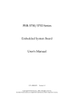
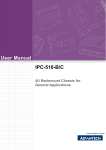
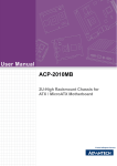
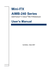
AIMB-C300
Multifunction Chassis for
EmbATX motherboard
User Manual
Copyright
Advantech Co., Ltd copyrights this documentation and the software
included with this product in 2005. All rights are reserved. Advantech
Co., Ltd. reserves the right to make improvements in the products
described in this manual at any time without notice.
No part of this manual may be reproduced, copied, translated or transmitted in any form or by any means without the prior written permission of
Advantech Co., Ltd. Information provided in this manual is intended to
be accurate and reliable. However, Advantech Co., Ltd. assumes no
responsibility for its use, or for any infringements of the rights of third
parties, which may result from its use.
Acknowledgements
IBM and PC are trademarks of International Business Machines Corporation.
On-line Technical Support
For technical support and service, please visit our support website at:
http://www.advantech.com/support
This manual is for the AIMB-C300.
Part No. 2006C30001
2nd Edition,
Nov. 2005
AIMB-C300 User Manual
II
FCC
This device complies with the requirements
in part 15of the FCC rule:Operation is
subject to be following two conditions:
(1)this device may not cause harmful interference
(2)this device must accept any interference
received, including interference that may cause
undesired operation.
III
AIMB-C300 User Manual
IV
Contents
Chapter
1 General Information ........................................2
1.1
1.2
1.3
Introduction ....................................................................... 2
Specification...................................................................... 2
Power Supply ............................................................. 3
1.4
Dimension Diagram .......................................................... 4
Table 1.1:Power Supply ...........................................................3
Figure 1.1:Dimension Diagram ...................................... 4
Chapter
2 System Setup.....................................................6
2.1
Removing the top cover .................................................... 6
2.2
2.3
Chassis Front and Rear Sections ....................................... 6
The HDD Drive Bay ......................................................... 7
Figure 2.1: Remove the top cover................................... 6
Figure 2.2:HDD drive bay .............................................. 7
Figure 2.3:Install the standard drive bay ........................ 8
2.4
The Standard Drive Bay.................................................... 8
Figure 2.4:Insert the drives ............................................. 8
Figure 2.5:Install the standard drive bay ........................ 9
2.5
PCI Riser card ................................................................... 9
2.6
System Status Indicator .................................................. 10
2.7
Cooling Fan & Filter ....................................................... 10
Figure 2.6:PCI riser card................................................. 9
Table 2.1:System Status LED....................................... 10
Figure 2.7:Cooling fans ................................................ 10
Figure 2.8:System Filter ............................................... 11
2.8
Front Panel Switches....................................................... 11
Figure 2.9:Front Panel Switches................................... 11
Appendix A Safety Instructions .........................................14
A.1
Safety Instructions........................................................... 14
V
AIMB-C300 User Manual
VI
CHAPTER
1
General Information
Chapter 1 General Information
1.1 Introduction
The AIMB-C300 is a industrial computer chassis designed for space-conscious applications. Customers can expand their business without having
to worry about space efficiency because the AIMB-C300 supports for
Embedded ATX series industrial motherboards. Fast-growing Internet
service providers and corporate enterprise customers can use the AIMBC300 as computing platforms for their mission critical applications. This
chassis comes with 200W ATX PFC power supply, dual abundant cooling fans, front-accessible air filter, USB, PS/2 keyboard connector, system reset, system alarm reset and system power switch. The viewable
LED indicators on front door support alarm notification of system status.
This ultra-compact 2U ATX M/B form factor delivers rack space optimization without sacrificing performance, expandability, serviceability, or
manageability.
1.2 Specification
• Expansion Driver Bay: 2x3.5” Hard Disk, 1 slim CD, 1 FDD or Card
Reader
• Small Module: Support Display Small Module
• Button: Power Switch Button, Reset Button
• Front Key Lock & Air Filter
• PCI slot: 1 PCI Riser Card
• LED: 1 Green LED light (Power on) 1 Yellow LED Light (HDD active)
• Wall Mount: Wall Mount Tool For Vertical/Parallel (optional)
• Cable kits: 1 USB Cable
• I/O panel Blank (default)
• 4 COMs (optional)
• Operating temperature: 0 ~ 40×°C (32 ~ 104×°F)
• Non-operating temperature: -20 ~ 60×°C (-4 ~ 140×°F)
• Relative humidity: 10 ~ 95% @ 40×°C, non-condensing
AIMB-C300 User Manual
2
• Shock resistance: 30 G acceleration, peak to peak, 11 ms (non-operating) 10 G acceleration peak to peak, 11 ms acceleration peak to peak
(operating)
• Vibration: 5 ~ 500 Hz, 0.5 G sine wave, and 5 ~ 500 Hz, 1 G (rms.) random
• Dimensions (W x H x D): 383 x 362 x 90.9mm
• Safety: CE compliant, C-UL approved
1.3 Power Supply
Table 1.1: Power Supply
Model
Watt Input
Name
1757000112 200W 90~264
(ATX, PFC)
Vac(Full
-range)
Output
Safety&
MTBF
+5 V @ 35 A +5V @ 3A
UL1950,
+3.3 V @ 20A +12V @ 2A
CSA 22.2
+12 V @ 16 A -5V @ 0.05A- NO/960,
-12 V @ 1A
12V @ 0.05A TUV IEC
-5 V @ 0.5 A +3.3V @ 1A
950
+5 Vsb @ 2 A +5Vsb @ 0.1A
3
Mini-load
Chapter 1
1.4 Dimension Diagram
Figure 1.1: Dimension Diagram
AIMB-C300 User Manual
4
CHAPTER
2
System Setup
Chapter 2 System Setup
WARNING: Before starting the installation process, turn off the power
switch and disconnect the system power cord from the chassis, or unplug
the power cord from the power outlet. When in doubt, consult with an
experienced technician.
2.1 Removing the top cover
First, remove the chassis cover by two M3 screws, which are on the rear
location of chassis.
To remove the top cover:
1. Detach the two screws on the rear side.
2. Lift off the cover.
IMPORTANT: Make sure you fully remove the top cover when maintaining full-size cards.
Check all the power supply cables and make certain that they are not tangled or blocking the cooling fan blades. This prevents any accidental
damage to the cables.(please refer Figure2-1)
PS: We assume the board has already been placed inside.
Figure 2.1: Remove the top cover
2.2 Chassis Front and Rear Sections
The AIMB-C300 comes in two sections: the front section and rear section.
The front section includes:
AIMB-C300 User Manual
6
1.Standard drive bay.
2.HDD bay.
3.Front chassis door.
The rear section includes:
1.Backplane.
2.Power supply with two fans.
3.Bracket for COM port
2.3 The HDD Drive Bay
The HDD drive bay of the AIMB-C300 can hold up to two hard disk.
Installing disk drives
1.Remove the top cover.
2.Detach the two screws holding the HDD bay.
3.Lift off the HDD bay.
4.Insert Hard Disks into their proper locations in the drive bay and secure
them with the screws provided.(please refer to figure 2-2).
5.Connect the disk drive power and signal cables.
6.Install the standard drive bay and secure the top front cover with the
two screws.(please refer to figure 2-3)
Figure 2.2: HDD drive bay
7
Chapter 2
Figure 2.3: Install the standard drive bay
2.4 The Standard Drive Bay
The standard drive bay of the AIMB-C300 can hold one 3.5" FDD or
Card reader (optional) and one Slim CD ROM.
1.Remove the top cover.
2.Detach the two screws holding the standard drive bay.(You could
remove the power supply first, it will easier to insert drive bay).
3.Lift off the standard drive bay.
4.Insert the drives into their proper locations in the drive bay and secure
them with the screws provided.(please refer to figure 2-4).
5.Connect the disk drive power and signal cables.
6.Install the standard drive bay and secure the top front cover with the
two screws.(please refer to figure 2-5)
Figure 2.4: Insert the drives
AIMB-C300 User Manual
8
Figure 2.5: Install the standard drive bay
2.5 PCI Riser card
Please follow the below installation guide to install PCI riser card into
AIMB-C300.
1. 32 bit PCI riser card
Install the PCI riser card to the proper location with the provided two
screws.(please refer to figure 2-6)
Figure 2.6: PCI riser card
2. 64 bit PCI riser card
First, you have to take away the screw on the original location to avoid
the riser card damage.Then just install the riser card to the proper location
with the two screws.
9
Chapter 2
2.6 System Status Indicator
Table 2.1: System Status LED
LED
Description
RED
GREEN or Orange
PWR
System Power
N/A
Normal
HDD
Hard Drive activity
N/A
Data access
PWR LED turns on, it indicates system power on.
HDD LED turns on, it indicates HDD data access
2.7 Cooling Fan & Filter
There are dual cooling fans as shown in figure 2-7 located inside the
chassis. The cooling fans are low maintenance and provide adequate
cooling to the system. If one of those cooling fails, please undo the two
screws on the dual cooling fan holder. Replace the failed cooling fan with
a good one. Please refer to figure2-7.
Figure 2.7: Cooling fans
Please refer the figure 2-8 to change the filter if you find the filter is
blocked with dust or other particles
AIMB-C300 User Manual
10
Figure 2.8: System Filter
2.8 Front Panel Switches
The front panel switches are used for system power and system reset.
Power On/Off switch is used for switching the system on or off. The System Reset switch re-initializes the system. This switch is similar to the
hardware reset button.
Figure 2.9: Front Panel Switches
11
Chapter 2
AIMB-C300 User Manual
12
Appendix
Safety Instructions
A
Appendix A Safety Instructions
A.1 Safety Instructions
1. Read these safety instructions carefully.
2. Keep this User Manual for later reference.
3. Disconnect this equipment from any AC outlet before cleaning. Do not
use a damp cloth, liquid or spray detergents for cleaning.
4. For plug-in equipment, the power outlet socket must be located near
the equipment and must be easily accessible.
5. Keep this equipment away from humidity.
6. Put this equipment on a reliable surface during installation. Dropping it
or letting it fall may cause damage.
7. The openings on the enclosure are for air convection. Protect the equipment from overheating. DO NOT COVER THE OPENINGS.
8. Make sure the voltage of the power source is correct before connecting
the equipment to the power outlet.
9. Position the power cord so that people cannot step on it. Do not place
anything over the power cord.
10. All cautions and warnings on the equipment should be noted.
11. If the equipment is not used for a long time, disconnect it from the
power source to avoid damage by transient over-voltage.
12. Never pour any liquid into an opening. This may cause fire or electrical shock.
13. Never open the equipment. For safety reasons, the equipment should
be opened only by qualified service personnel.
14. If one of the following situations arises, get the equipment checked by
service personnel:
a. The power cord or plug is damaged.
b. Liquid has penetrated into the equipment.
c. The equipment has been exposed to moisture.
d. The equipment does not work well, or you cannot get it to work
according to the user manual.
e. The equipment has been dropped and damaged.
f. The equipment has obvious signs of breakage.
AIMB-C300 User Manual
14
15. DO NOT LEAVE THIS EQUIPMENT IN AN ENVIRONMENT
WHERE THE STORAGE TEMPERATURE MAY GO BELOW -20× C
(-4× F) OR ABOVE 60× C (140× F). THIS COULD DAMAGE THE
EQUIPMENT. THE EQUIPMENT SHOULD BE IN A CONTROLLED
ENVIRONMENT.
The sound pressure level at the operator’s position according to IEC 7041:1982 is no more than 70dB(A).
DISCLAIMER: This set of instructions is given according to IEC 704-1.
Advantech disclaims all responsibility for the accuracy of any statements
contained herein.
16. Any insulation on conductors inside EQUIPMENT which are connected to ACCESSIBLE METAL PARTS or other PROTECTIVELY
EARTHED parts with a protective function to the PROTECTIVE
EARTH TERMINAL shall be identified by the colors green and yellow at
the termination of the conductors.
17. CAUTION: The computer is provided with a Battery-powered RealTime Clock Circuit. There is a danger of explosion if battery is incorrectly replaced. Replace only with same or equivalent typed recommended by the manufacturer. Discard use batteries according to the
manufacturer’s instructions.
18. The computer is provided with appropriate safety standards including
lec 60826.
19. Install the computer. Before your begin make sure the Green/Yellow
wire reliable connection between metal part of computer and earthing of
final system.
15
Appendix A
AIMB-C300 User Manual
16