1
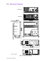
User Manual
IPC-510-B/C
4U Rackmount Chassis for
General Applications
Copyright
The documentation and the software included with this product are copyrighted 2009
by Advantech Co., Ltd. All rights are reserved. Advantech Co., Ltd. reserves the right
to make improvements in the products described in this manual at any time without
notice.
No part of this manual may be reproduced, copied, translated or transmitted in any
form or by any means without the prior written permission of Advantech Co., Ltd.
Information provided in this manual is intended to be accurate and reliable. However,
Advantech Co., Ltd. assumes no responsibility for its use, nor for any infringements
of the rights of third parties, which may result from its use.
Acknowledgements
The IPC-510, AIMB-742, AIMB-744, AIMB-750, AIMB-760, AIMB-762, AIMB-763,
AIMB-764, AIMB-766, PCA-6114P4, PCA-6114P7, PCA-6114P10, PCA-6114P12
and PCA-6114P12X are trademarks of Advantech Co., Ltd.
All other product names or trademarks are properties of their respective owners.
On-line Technical Support
For technical support and service, please visit our support website at:
http://support.advantech.com/support
IPC-510-B/C User Manual
Part No. 2002051021
Edition 2
Printed in China
March 2009
ii
Safety Instructions
1.
2.
3.
4.
5.
6.
7.
8.
9.
10.
11.
12.
13.
14.
15.
16.
17.
Read these safety instructions carefully.
Keep this User Manual for later reference.
Disconnect this equipment from any AC outlet before cleaning. Use a damp
cloth. Do not use liquid or spray detergents for cleaning.
For plug-in equipment, the power outlet socket must be located near the equipment and must be easily accessible.
Keep this equipment away from humidity.
Put this equipment on a reliable surface during installation. Dropping it or letting
it fall may cause damage.
Do not leave this equipment in an environment unconditioned where the storage
temperature under 0° C (32° F) or above 40° C (104° F), it may damage the
equipment.
The openings on the enclosure are for air convection. Protect the equipment
from overheating. DO NOT COVER THE OPENINGS.
Make sure the voltage of the power source is correct before connecting the
equipment to the power outlet.
Place the power cord such a way that people can not step on it. Do not place
anything over the power cord. The voltage and current rating of the cord should
be greater than the voltage and current rating marked on the product.
All cautions and warnings on the equipment should be noted.
If the equipment is not used for a long time, disconnect it from the power source
to avoid damage by transient overvoltage.
Never pour any liquid into an opening. This may cause fire or electrical shock.
Never open the equipment. For safety reasons, the equipment should be
opened only by qualified service personnel.
If one of the following situations arises, get the equipment checked by service
personnel:
! The power cord or plug is damaged.
! Liquid has penetrated into the equipment.
! The equipment has been exposed to moisture.
! The equipment does not work well, or you cannot get it to work according to
the user's manual.
! The equipment has been dropped and damaged.
! The equipment has obvious signs of breakage.
CAUTION: The computer is provided with a battery-powered real-time clock circuit. There is a danger of explosion if battery is incorrectly replaced. Replace
only with same or equivalent type recommended by the manufacture. Discard
used batteries according to the manufacturer’s instructions.
THE COMPUTER IS PROVIDED WITH CD DRIVES COMPLY WITH APPROPRIATE SAFETY STANDARDS INCLUDING IEC 60825.
CLASS 1 LASER PRODUCT
KLASSE 1 LASER PRODUKT
iii
IPC-510-B/C User Manual
18. This device complies with Part 15 of the FCC rules. Operation is subject to the
following two conditions:
1) This device may not cause harmful interference, and
2) This device must accept any interference received, including interference that
may cause undesired operation.
19. CAUTION: Always completely disconnect the power cord from your chassis
whenever you work with the hardware. Do not make connections while the
power is on. Sensitive electronic components can be damaged by sudden
power surges.
20. CAUTION: Always ground yourself to remove any static charge before touching
the motherboard, backplane, or add-on cards. Modern electronic devices are
very sensitive to static electric charges. As a safety precaution, use a grounding
wrist strap at all times. Place all electronic components on a static-dissipative
surface or in a static-shielded bag when they are not in the chassis.
21. CAUTION: Any unverified component could cause unexpected damage. To
ensure the correct installation, please always use the components (ex. screws)
provided with the accessory box.
A Message to the Customer
Advantech customer services
Each and every Advantech product is built to the most exacting specifications to
ensure reliable performance in the harsh and demanding conditions typical of industrial environments. Whether your new Advantech equipment is destined for the laboratory or the factory floor, you can be assured that your product will provide the
reliability and ease of operation for which the name Advantech has come to be
known. Your satisfaction is our primary concern. Here is a guide to Advantech's customer services. To ensure you get the full benefit of our services, please follow the
instructions below carefully.
Technical support
We want you to get the maximum performance from your products. So if you run into
technical difficulties, we are here to help. For the most frequently asked questions,
you can easily find answers in your product documentation. These answers are normally a lot more detailed than the ones we can give over the phone.
So please consult this manual first. If you still cannot find the answer, gather all the
information or questions that apply to your problem, and with the product close at
hand, call your dealer. Our dealers are well trained and ready to give you the support
you need to get the most from your Advantech products. In fact, most problems
reported are minor and can be easily solved over the phone.
In addition, free technical support is available from Advantech engineers every business day. We are always ready to give advice on application requirements or specific
information on the installation and operation of any of our products.
IPC-510-B/C User Manual
iv
Product Warranty
Advantech warrants to you, the original purchaser, that each of its products will be
free from defects in materials and workmanship for two years from the date of purchase.
This warranty does not apply to any products which have been repaired or altered by
persons other than repair personnel authorized by Advantech, or which have been
subject to misuse, abuse, accident or improper installation. Advantech assumes no
liability under the terms of this warranty as a consequence of such events.
Because of Advantech’s high quality-control standards and rigorous testing, most of
our customers never need to use our repair service. If an Advantech product is defective, it will be repaired or replaced at no charge during the warranty period. For outof-warranty repairs, you will be billed according to the cost of replacement materials,
service time and freight. Please consult your dealer for more details.
If you think you have a defective product, follow these steps:
1. Collect all the information about the problem encountered. (For example, CPU
speed, Advantech products used, other hardware and software used, etc.) Note
anything abnormal and list any onscreen messages you get when the problem
occurs.
2. Call your dealer and describe the problem. Please have your manual, product,
and any helpful information readily available.
3. If your product is diagnosed as defective, obtain an RMA (return merchandise
authorization) number from your dealer. This allows us to process your return
more quickly.
4. Carefully pack the defective product, a fully-completed Repair and Replacement
Order Card and a photocopy proof of purchase date (such as your sales receipt)
in a shippable container. A product returned without proof of the purchase date
is not eligible for warranty service.
5. Write the RMA number visibly on the outside of the package and ship it prepaid
to your dealer.
Initial Inspection
When you open the carton, please make sure that the following materials have been
shipped:
! IPC-510 Chassis
! User Manual
! Warranty Card
! Accessory box with a package of screws (for fastening the backplane or motherboard, optical disk drive, other disk drives, ear handles, etc.), a pair of keys, a pc
of EMI spring shielding (for backplane version), 15 pcs rubber cushions (backplane version) or 7 pcs (motherboard version), and a pair of ear handles.
If any of these items are missing or damaged, contact your distributor or sales representative immediately. We have carefully inspected the IPC-510 mechanically and
electrically before shipment. It should be free of marks and scratches and in perfect
working order upon receipt. As you unpack the IPC-510, check it for signs of shipping
damage. (For example, damaged box, scratches, dents, etc.) If it is damaged or it
fails to meet the specifications, notify our service department or your local sales representative immediately. Also, please notify the carrier. Retain the shipping carton
and packing material for inspection by the carrier. After inspection, we will make
arrangements to repair or replace the unit.
v
IPC-510-B/C User Manual
IPC-510-B/C User Manual
vi
Contents
Chapter
1
General Information ............................1
1.1
1.2
Introduction ............................................................................................... 2
Specification.............................................................................................. 3
Table 1.1: Specification ............................................................... 3
Power Supply Options............................................................................... 3
Table 1.2: Power Supply Options ................................................ 3
Dimension Diagram................................................................................... 4
Figure 1.1 Dimension diagram..................................................... 4
1.3
1.4
Chapter
2
System Setup .......................................5
2.1
2.2
2.4
Removing the top cover ............................................................................ 6
Installing the backplane or motherboard ................................................... 6
Figure 2.1 Yellow label indicating copper stub locations ............. 7
Installing disk drives .................................................................................. 7
Figure 2.2 Disk drive bay ............................................................. 7
Attaching the ears & handles .................................................................... 7
3
Operation..............................................9
3.1
Chassis front panel ................................................................................. 10
Figure 3.1 Front view ................................................................. 10
3.1.1 Switch, Button and I/O interfaces................................................ 10
3.1.2 LED Indicators for System Status ............................................... 10
Replacing cooling fan and filter ............................................................... 11
Figure 3.2 Replacing the Cooling fan & filter ............................. 11
2.3
Chapter
3.2
Appendix A
Exploded Diagram & Parts List ........13
A.1
Exploded Diagram & Parts List ............................................................... 14
Table A.1: Parts List................................................................... 14
Appendix B
Backplane & Motherboard Options .15
B.1
Backplane Options .................................................................................. 16
Table B.1: Backplane Options ................................................... 16
Motherboard Options .............................................................................. 16
Table B.2: ATX Motherboard Options........................................ 16
B.2
vii
IPC-510-B/C User Manual
IPC-510-B/C User Manual
viii
Chapter
1
1
General Information
This chapter provides general
information about the
IPC-510-B/C.
Sections include:
! Introduction
! Specifications
! Power Supply Options
! Dimension Diagram
1.1 Introduction
IPC-510-B/C is a 4U IPC rackmount chassis which includes a 14-slot ISA or ISA/PCI
backplane and a 250 W / 300 W ATX PFC PS/2 power supply. It is the best price-performance industrial chassis platform for building mission-critical applications.
IPC-510-B/C has a shockproof design with front-accessible drive bays for easy
installation of three half-height 5.25" drives, one 3.5" FDD, USB devices, and a PS/2
keyboard connector. The design also includes one internal 3.5" HDD drive bay. For
high-density applications, IPC-510-B/C supports a range of ISA/PCI backplanes, with
the ATX M/B version and a 250 W / 300 W ATX PFC power supply optional.
IPC-510-B/C is a rack-optimized IPC chassis that offers the best total cost of ownership and scalability for customers who want to grow their businesses without increasing costs. A wide range of standard computing peripherals can be integrated with the
chassis to meet different application development requirements under mission-critical environments.
IPC-510-B/C User Manual
2
Table 1.1: Specifications
Drive Bay
Cooling
Miscellaneous
Internal
3.5"
1
1
5.25"
3
Fan
1 (77 CFM/each)
USB
2 (front-accessible)
PS/2
1 (front-accessible)
Rear panel Indicator
BP version: Two D-SUB 9-pin openings
MB version: One D-SUB 9-pin bracket and one
68-pin SCSI openings
LED display for power on and HDD activity
Operating
Environment
Physical
Compliance
Non-Operating
Temperature
0 ~ 40° C (32 ~ 104° F) -20 ~ 60° C (-4 ~ 140° C)
Humidity
10 ~ 85%
10 ~ 95%
Vibration (5-500 Hz)
1 Grms
2G
Shock
10 G (With 11 msec
30 G
duration, 1/2 sine wave)
Altitude
10,000 ft
Acoustic Noise
Less than 52dB sound pressure at 5 ~ 28° C
(41 ~ 82° F)
40,000 ft
Dimensions (W x H x D) 482 x 177 x 448 mm (19" x 7" x 17.6")
Weight
12.5 kg (27.5 lb)
Safety
CE compliant
1.3 Power Supply Options
Table 1.2: Power Supply Options
Model Name
PS-250ATX-ZE
PS-300ATX-ZBE
Watt
250 W ATX, PFC
300 W ATX, PFC
Input
115/230 VAC (Selected)
100 ~ 240 Vac (Full-range)
Output
+5 V @ 27 A, +3.3 V @ 20 A,
+12 V @ 13 A, 12 V @ 0.8 A,
-5 V @ 0.3 A, +5 Vsb @ 2 A
+5 V @ 30 A, +3.3 V @ 28 A,
+12 V @ 15 A, -12 V @ 0.8 A,
-5 V @ 0.3 A, +5 Vsb @ 2 A
Mini-load
+5 V @ 0.5 A, +3.3 V @ 0.3 A
+5 V @ 0.1 A, +3.3 V @ 0.3A
MTBF
100,000 hours @ 25° C
100,000 hours @ 25° C
Safety
UL/TUV/CB/CCC
UL/TUV/CB/CCC
3
IPC-510-B/C User Manual
General Information
I/O Interface
Front-accessible
Chapter 1
1.2 Specifications
1.4 Dimension Diagram
Motherboard
Backplane
Unit: mm [inch]
Figure 1.1 Dimension diagram
IPC-510-B/C User Manual
4
Chapter
2
2
System Setup
This chapter introduce the installation process.
Sections include:
! Removing the top cover
! Installing a backplane or motherboard
! Installing disk drives
! Attaching the ears and handles
The following procedures instruct users to install a backplane/motherboard, add-on
cards and disk drives into the IPC-510. Please also refer to Appendix A, Exploded
Diagram, for the detailed parts of IPC-510.
Caution! Use caution when installing or operating the components with the chassis open. Be sure to turn off the power, unplug the power cord and
ground yourself by touching the metal chassis before you handle any
components inside the machine.
2.1 Removing the top cover
Please remove the chassis cover by releasing the two screws which are on rear of
chassis.
2.2 Installing the backplane or motherboard
These chassis supports either a backplane with up to 15 slots, or an ATX motherboard. To install the backplane or motherboard, please proceed as follows:
Note!
1.
2.
3.
4.
5.
6.
7.
8.
Use caution when installing a motherboard. It's highly recommended to
integrate Advantech motherboard series with this chassis to ensure the
quality, safety, and optimized air flow design.
Dismantle the hold-down clamp by removing the two screws on both its ends.
A yellow label is located inside the chassis bottom. (see Figure 2.1) It shows the
copper stub locations for attaching the specific backplane or motherboard.
Users can find the copper stubs in the accessory box. Be sure to follow the
instructions, and fasten the backplane or motherboard onto the chassis with the
correct stub locations.
While installing a BACKPLANE, fasten it in place and attach the supplied EMI
spring shielding with the screws provided.
For the PICMG 1.0 BACKPLANE, connect the orange-white wire from connector ‘HCN1’ on the backplane to connector ‘CN21’ on the CPU card.
While installing a MOTHERBOARD, attach the motherboard I/O shielding onto
the rear plate first. Then fasten the motherboard onto the chassis.
Connect the 20-pin (or 24-pin) ATX power connector and the 4-pin +12V power
connector from the power supply to the backplane or the motherboard. (For the
PICMG 1.0 BACKPLANE, the 4-pin +12 V power connector is connected to the
CPU card.)
Connect the 9-pin USB wire, PS/2 wire, power switch wire, and the system reset
switch wire from the chassis to the motherboard.
Connect the HDD LED wire from the chassis to the motherboard.
IPC-510-B/C User Manual
6
1
2
3
4
5
6
7
8
9
10 11 12 13 14 15 16 17 18 19 20 21 22 23 24 25 26 27 28 29
X
A M
Be careful to screw the Copper Stub under 10 kgf cm.
Figure 2.1 Yellow label indicating copper stub locations
2.3 Installing Disk Drives
You can remove the disk drive bay form the chassis by removing the four screws
from the disk drive bay. After installing each disk drive in place, then return the whole
drive bay unit into the chassis and fasten it. Then connect the suitable cables (ex.
IDE, SATA or SAS, etc.) from the motherboard or CPU card and plug the power connectors from the power supply.
Figure 2.2 Disk drive bay
2.4 Attaching the Ears & Handles
There are a pair of ears and a pair of handles in the accessory box. If you need to
install the chassis in a rack, just attach the ears and handles to the front corners of
the unit using the screws provided.
7
IPC-510-B/C User Manual
System Setup
PCA-6113P4R
PCA-6114P7
PCA-6114P12
PCA-6114P4
PCA-6114P10
PCA-6114-B
PCA-6113P7X
PCA-6115
PCA-6114P12X
PCE-7B13-64
PCE-5B12-64
AIMB-740
AIMB-742
AIMB-744
AIMB-750
AIMB-760
AIMB-762
AIMB-764
AIMB-542
AIMB-554
AIMB-556
AIMB-560
AIMB-562
Chapter 2
NUT NUMBER
BP/MP MODEL
IPC-510-B/C User Manual
8
Chapter
3
3
Operation
This chapter introduces the system operation information.
Sections include:
! The front panel
! Replacing the cooling fan
! Replacing the filter
3.1 Chassis front panel
The front panel features a lockable door and six LED indicators. There are a dual
USB port, a PS/2 port, a Power LED and an HDD LED on the left of the front panel.
When opening the door, there is a system reset button and a momentary power
switch.
Figure 3.1 Front view
3.1.1 Switch, Button and I/O interfaces
Momentary Power switch: Press this switch to turn the system power on or off.
Please use system shutdown or press this switch for few seconds to turn off the system ATX power.
System Reset button: Press this button to reboot the system.
Dual USB ports: For connecting a wide range of USB devices for data transfer,
backup or input.
PS/2 port: For connecting the keyboard or mouse, depending on the features of the
motherboard/CPU card.
3.1.2 LED Indicators for System Status
There are two LEDs: one indicates the system power supply status and the other the
hard disk drive activity.
When the system power is on, the power LED glows steady Green.
When the power LED is RED, it indicates a redundant power supply module failure.
To stop the alarm beeping, press the Alarm Reset button. Examine the redundant
power supply module right away and replace the failed module with a good one.
The HDD LED blinks Green while data is transferring.
IPC-510-B/C User Manual
10
Refer Figure 3.2 to find the location of the system cooling fan and filter. Please
replace the system cooling fan if either is defective. The filter functions to block dust
or particles coming from the work environment and to extend the longevity of the system. It is better to replace the filter periodically. To replace the filter, open the front
door and simply pull out the fan filter behind the left panel. Then put a new filter in
place.
Chapter 3
3.2 Replacing Cooling Fan and Filter
Operation
Figure 3.2 Replacing the Cooling fan & filter
11
IPC-510-B/C User Manual
IPC-510-B/C User Manual
12
Appendix
A
A
Exploded Diagram &
Parts List
A.1 Exploded Diagram & Parts List
1
2
3
4
5
6
18
7
17
8
19
9
16
20
15
10
11
12
14
13
Table A.1: Parts List
1
Top cover
11
Hinge
2
Hold down clamp
12
Front door
3
Drive bay
13
Rackmount ear
4
5.25" CD-ROM cover
14
Handles
5
Card guide
15
Body of chassis
6
Card guide bracket
16
Disk mounting bracket
7
Fan bracket
17
I/O bracket
8
120 mm fan set
18
Adapter bracket
9
USB & PS/2
19
Rear window bracket
10
Filter cover
20
Power supply
IPC-510-B/C User Manual
14
Appendix
B
B
Backplane &
Motherboard Options
B.1 Backplane Options
IPC-510 supports a variety of PICMG 1.0 backplanes. Users can contact a local
sales representative for detailed specifications and information.
Table B.1: Backplane Options
Model Name
Segment
PCA-6115
PCA-6114
Slots Per Segment
PICMG
PICMG/PCI PCI
ISA
Single
-
-
-
15
Single
-
-
-
14
PCA-6114P4
Single
2
-
4
8
PCA-6114P7
Single
3
1
6
4
PCA-6114P10
Single
2
-
10
2
PCA-6114P12
Single
1
1
11
1
PCA-6114P12X
Single
1
1
11
1
PCA-6113P4R
Single
2
-
4
7
PCA-6113P7XE
Single
2
-
7
4
B.2 Motherboard Options
IPC-510 supports a variety of Advantech ATX motherboards, as shown below. Users
can contact a local sales representative for detailed information.
Table B.2: ATX Motherboard Options
Model Name
Slots Per Segment
PCi
PCI/ISA
ISA
AGP
SATA
AIMB-740
4 (32-bit)
1
1
-
-
AIMB-742
4 (32-bit)
1
1
1 (8X)
-
AIMB-744
2 (PCI-X 64-bit)
4 (PCI 32-bit)
-
-
1 (8X)
2
AIMB-750
2 (PCI-X 64-bit)
4 (PCI 32-bit)
-
-
1 (4X)
2
AIMB-760
1 (PCI-E 1X)
5 (PCI 32-bit)
-
-
-
4
AIMB-762
1 (PCIe 16X)
1 (PCIe 4X)
5 (PCI 32-bit)
-
-
-
4
AIMB-763
1 (PCIe 16X)
1 (PCIe 1X)
5 (PCI 32-bit)
-
-
-
4
AIMB-764
1 (PCIe 16X)
1 (PCIe 4X)
5 (PCI 32-bit)
-
-
-
5
AIMB-766
1 (PCIe 16X)
2 (PCIe 1X)
4 (PCI 32-bit)
-
-
-
6
IPC-510-B/C User Manual
16
Appendix B Backplane & Motherboard Options
IPC-510-B/C User Manual
17
www.advantech.com
Please verify specifications before quoting. This guide is intended for reference
purposes only.
All product specifications are subject to change without notice.
No part of this publication may be reproduced in any form or by any means,
electronic, photocopying, recording or otherwise, without prior written permission of the publisher.
All brand and product names are trademarks or registered trademarks of their
respective companies.
© Advantech Co., Ltd. 2009