1
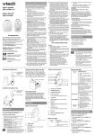
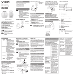
The
PULL-FOR-HELP
Emergency Caller
Model 10-4 Automated Call for Help! System
OWNER’S MANUAL
AND
OPERATING INSTRUCTIONS
UNITED SECURITY
PRODUCTS, INC.
GETS
HELP
FAST!
Federal Communications Commission Radio
and Television Interference Statement for A
Class ‘B’ Device
This equipment generates and uses radio frequency energy and if not
installed and used properly, that is, in strict accordance with the
manufacturer’s instructions, may cause interference to radio and television
reception. It has been type tested and found to comply with the limits for a
Class ‘B’ computing device in accordance with the specifications in Subpart
B of FCC Rules and Regulations (as outlined in the Code of Federal
Regulation, Title 47), which are designed to provide reasonable protection
against such interference in a residential installation.
User Instructions:
If this equipment does cause interference to radio or television reception,
which can be determined by turning the equipment off, then on, the user is
encouraged to try to correct the interference by one or more of the following
measures:
• Reorient or relocate radio or television.
• Increase the separation between the equipment and receiver.
• Connect the equipment into a different outlet so that the equipment and
receiver are on different branch circuits.
• Consult the dealer or an experienced radio/TV technician for help.
Changes or modifications not expressly approved by United security
Products, Inc. could void the user’s authority to operate the equipment.
2
Important! Please Read This Page
Thank You for Purchasing The Emergency Caller from USP!
USP has made every effort to make The Emergency Caller the finest Personal
Emergency Response System on the market today. However, for your safety
please take the following precautions when using The Emergency Caller:
•
The Emergency Caller should be tested regularly to ensure proper delivery of
your pre-recorded emergency message when activated by the Pull-For-Help
transmitter or the Auxiliary input. This is your responsibility as the user of the
product.
•
Certain structures within a household may block the transmitter signal. It is up to
the user to test the transmitter within the area of use to determine if dead areas
exist, and where they are located.
•
Holding the transmitter next to your body or the ground while in use may
decrease the range of the transmitter signal.
•
Using The Emergency Caller does not guarantee that you will contact or receive
help. The Emergency Caller is only an aid to assist you in calling for help.
•
The transmitter should be tested frequently to protect against undetected
interference or fault.
•
For U.S. installations only: The Emergency Caller is required to comply with
Part 15 of the FCC Rules and regulations. As such, it has limited transmitter
power and therefore limited range.
•
The dialer cannot respond to more than one transmitted signal at a time and may
be blocked by radio signals that occur on or near their operating frequencies,
regardless of code setting.
•
Changes or modifications to the device may void FCC compliance.
3
The Emergency Caller… Gets Help Fast!
Congratulations!
Thank you for purchasing United Security Products, Inc.’s Emergency Caller - the “smartest”, most
comprehensive automatic voice/pager emergency dialer available. Representing an exciting new level of
achievement, The Emergency Caller combines technologically advanced features, ease of programming and
reliable operation in a compact, unobtrusive dialer. Installation and hookup are quick and easy. The unit is a
stand-alone wireless device that simply connects to an ordinary telephone jack. The keypad cover glides on and
off for added attractiveness and security.
How It Works:
The Emergency Caller features busy-line and no-answer detection to ensure prompt transmission of the
prerecorded message to as many as 4 standard telephones, cellular phones, voice and/or numeric pagers.
Message to both local and long-distance calls can be transmitted. When activated, the dialer instantly begins
calling the numbers in sequence, in an attempt to deliver the message or pager code. The Emergency Caller is
extensively programmable, offering personalized customization to fulfill virtually any residence. Plain-English
prompts walk the user through the process in a timely manner.
Programming options abound, allowing the user to:
• Store up to 4 telephone/pager numbers.
• Store an emergency message (maximum: 20 sec.).
• Select Tone/Pulse dialing, Standard telephone line/PBX system and Momentary/Continuous activation.
Special Features:
• The dialer will “beep” every 30 seconds in the Program and Test mode. This is to warn the user that the
dialer is not in the Operate or Off mode.
• In the Test mode, when testing the input, the dialer will check to make sure that there is a dial tone. If no
dial tone is detected, the dialer will not continue testing the input and will display:
NO DIAL TONE!
(Connect the dialer to the telephone line and re-test the input). Note: Although the dialer checks for a dial
tone it will not actually dial out.
• The dialer will check to make sure that, at least, one telephone number and OGM or one pager number is
programmed before allowing the dialer to be switched to the Operate mode. If programming is not
complete, the dialer will display:
PROGRAMMING IS
NOT COMPLETE!
(After 2 seconds the dialer will automatically switch to the Programming mode).
Please Familiarize Yourself With These Instructions Before Installation/Operation. This guide describes how to
program and operate the dialer. We strongly recommend that you read the entire manual before attempting to
use the unit.
To enhance ease of programming and operation, this guide includes:
• A Programming Sample/Quick Setup review on page 20 with a corresponding Program Planner.
• A Blank Program Planner on page 21. One copy of this Planner should be kept in a safe place by the end
user. A separate copy should also be retained by the installer.
4
Table of Contents
Section
Page number
Package contents…………………………………………………………………
6
Care and Precautions……………………………………………………………..
7
Panel Displays……………………………………………………………………
8
Installation Hookup………………………………………………………………
9
The Pull-For-Help Transmitter…………………………………………………..
10
The Pull-For-Help Transmitter necklace…………………………………………
11
Programming The Emergency Caller…………………………………………….
12
Overview………………………………………………………………………
12
Programming Phone/Pager Numbers………………………………………….
13-14
Programming Auxiliary Information, OGM and Input.……………………….
15-16
Testing Your System…………………………………………………………..
17
Operating Your System and Additional Features………………………………..
18-19
Programming Example and Sample Program Planner…………………………..
20
Blank Program Planner…………………………………………………………..
21
Weekly Test Log…………………………………………………………………
22
Specifications and Dialer Accessories..………………………………………….
23
The Emergency Caller, by United Security Products, is a compact Personal Emergency Response
System. This full-featured unit provides fast, automatic emergency notification for single residents, latch-key
children, elderly people, illness sufferers and others who desire the reassurance of 24-hour peace of mind.
Combined with the cordless Pull-For-Help Transmitter, The Emergency Caller will call for help even if you are
unable to reach the telephone yourself!
EASY
•
•
•
Fast plug-in installation
Programs in minutes
Activates by pressing the Auxiliary input or remotely with the cordless Pull-For-Help Transmitter
VERSATILE
•
•
Communicates with up to 4 telephones, cellular phones and/or pager destinations
Can quickly change the 20-second personalized message and your programmed numbers
SECURE
•
•
•
Provides automatic, emergency communication 24 hours a day
Incorporates busy-line and no-answer detection, and will redial until the message is delivered
Operates despite power outages with built in battery backup
Important: Save These Instructions
5
Packaging Contents
As you unpack your Emergency Caller, check to make sure you have the following items:
1.
2.
3.
4.
5.
6.
7.
Emergency Caller Main unit
Long telephone line cord
Pull-For-Help Cordless Transmitter
9-12V AC/DC adaptor, with 3.5mm plug
Antenna
Pull-For-Help Transmitter Necklace with Stopper and Bead
Instruction Manual
1
5
3
4
2
6
6
Care and Precautions
WARNING: DO NOT EXPOSE UNIT TO RAIN OR MOISTURE. DO
NOT OPEN HOUSING.
LOCATION
Place the dialer on a flat level surface or mount the unit on the wall, away from
extreme cold or heat, direct sunlight, excessive humidity and away from equipment
that generate strong magnetic fields. Avoid placing near large metal objects and
areas that produce smoke, dust and mechanical vibrations.
CARE
Clean the housing with a soft cloth lightly moistened with water or mild detergent
solution. Never use solvents such as alcohol or thinner. Do not allow liquids to
spill into the unit.
PULL-FOR-HELP
TRANSMITTER
BATTERIES
The 3-Volt Lithium batteries (Duracell #2025 or equivalent) that are pre-installed
with your Pull-For-Help Transmitter are for testing purposes only. These batteries
should be replaced after purchase. Under normal use transmitter batteries should
last 12-18 months. Transmitter batteries should be replaced at least once a year.
OPTIONAL
BACKUP
To ensure continuous operation during power outages, hookup to a 12VDC backup
battery pack is recommended. (PP-1) Available from United Security Products.
CAUTION
Do not use the dialer if a gas leak is suspected or during lightning.
PROBLEMS
If liquid or a foreign object penetrates the unit, disconnect it immediately and
contact your installer or other qualified technician.
Before calling USP, please make sure…
•
•
•
You have read this manual and understand how to operate the dialer.
Your phone line is working.
You check out the entire system, including external hookup wiring and sensors
attached.
7
Panel Displays
8
Installation Hookup
*OPTIONAL
*OPTIONAL
*OPTIONAL
9
T h e P u l l - F o r- H e l p T r a n s m i t t e r
CAUTION:
We strongly recommend that you test your cordless PullFor-Help Transmitter with The Emergency Caller
frequently. From the time of installation, it is absolutely
necessary to test the system at least once a week to ensure
that The Emergency Caller will be ready when needed.
The batteries should be replaced every year.
Description
The Pull-For-Help Transmitter is a digitally coded miniature radio transmitter. The Pull-For-Help Transmitter is
powered by two long life, selp-contained 3-volt batteries. The transmitter is water-resistant but not waterproof.
Do not immerse in water.
Checkout And Test
Move at least six feet away from The Emergency Caller and activate the Pull-For-Help Transmitter by pulling
down on the cord attached to the bottom of the case. Emergency Caller activation indicates that the Pull-ForHelp Transmitter is operating properly and that the Pull-For-Help Transmitter’s digital code is correctly matched
to The Emergency Caller. To stop testing simply return the transmitter to its original closed position. Operate
the Pull-For-Help Transmitter from various locations within the area to be used. This will help to locate
areas where obstacles may interfere with transmission and will identify the range on the transmitter.
Changing The Batteries
To replace the batteries in your Pull-For-Help Transmitter you need 2, 3-volt Lithium batteries (Duracell #2025
or equivalent). First be sure to disconnect the dialer from the telephone line. Carefully remove the screws on
the transmitter case. Remove the clip from the transmitter case and separate the transmitter housing. Carefully
remove the circuit board inside, and avoid touching any of the components. Remove the old batteries from the
battery clip, and place the new batteries under the clip with the positive ends of both batteries facing up. Place
the circuit board back in the transmitter housing, and reassemble the transmitter case. After changing the
batteries be sure to reconnect the phone line and test the Pull-For-Help Transmitter to make sure you
have installed the batteres properly.
10
T h e P u l l - F o r- H e l p T r a n s m i t t e r N e c k l a c e
The Pull-For-Help Transmitter necklace was designed with your safety in mind. If for some reason the
necklace catches on something it has a release feature so you will not be injured. In addition, the necklace has an
adjustable bead that will comfortably secure the necklace around your neck so it cannot fall off during normal
everyday activities such as bending over, as well as during an accident or fall. The length of the necklace is
adjustable so you can customize it to your ideal size for a comfortable fit.
Adjusting The Length
To adjust the length of your Pull-For-Help Transmitter Necklace simply depress the button on the necklace
stopper and slide the necklace cord through the hole to the length you desire. When the correct size is obtained
simply release the stopper button.
Adjusting The Necklace Bead
To make sure the necklace will not fall off during everyday activities or in case of an accident, slide the necklace
bead toward your head until the loop around your neck will not easily slip off. Do not adjust the bead too tight,
the necklace should remain loose and comfortable. You can adjust the bead to an ideal comfortable fit.
Quick Release Feature
If for some reason the necklace becomes caught on an object, the necklace will release when enough pressure is
applied. When enough pressure is applied the necklace cord will slide through the stopper allowing the necklace
to separate and avoid any injury to the wearer. To reconnect the necklace simply depress the stopper button and
slide the ends of the necklace through the stopper hole. When the desired size is reached simply release the
stopper button.
Important: Never tie a knot in the necklace, as this will prevent
the emergency necklace feature from functioning.
11
Programming The Emergency Caller
Overview
Please study this section thoroughly before beginning to program the dialer, referring to the Sample Program
Planner on page 20. Then, select from among the options for each feature, listing each choice in pencil on the
blank Program Planner on page 21. Once the dialer is correctly programmed, list each choice in ink. One copy of
the Planner should be kept by the installer; one copy should remain with the end user.
A look At The Keypad
• CALLOUT FOR NUMERALS:
Press these keys to enter telephone numbers and other programming information as
specified in this manual. A maximum of 28 digits can be input in each phone/pager
location.
• CALLOUT FOR P:
Press this key to program in a pause. Each “P” provides a 2-second pause.
• CALLOUT FOR R:
Press this key to record the directional outgoing messages (OGMs). The total elapsed
OGM time cannot exceed 20 seconds.
• CALLOUT FOR M:
Press this key to change the Mode of the dialer, in sequence:
PROGRAM TEST OPERATE OFF.
Once the unit has been programmed, removing power or placing the dialer in the OFF mode will not affect the
programming.
12
Programming The Emergency Caller
First Time Installation to Initialize Dialer Follow Steps 1 & 2.
STEP 1 Apply power to the unit. The LCD will read:
STEP 2 Press 1. The LCD will change to read:
NOT PROGRAMMED
PRESS KEYPAD #1
EMERGENCY CALLER
USP (REVISION)
then: PROGRAM: NUMBERS
then: SELECT: 1-4
0(DONE)
Programming Telephone And/Or Pager Numbers
You are now ready to begin programming the dialer. All programming can be input before connecting the dialer
to a telephone line. Check the unit’s LCD as you program numbers in the dialer to ensure accuracy. Please
complete all programming instructions before attempting to operate the unit.
Before programming your dialer to call the police, fire department or 9-1-1 directly, you must check
with these agencies for their approval.
A maximum of 28 digits (including pauses) can be programmed in at each location.
*PROGRAM: NUMBERS
SELECT: 1-4
1(YES) 2(NO )
0(DONE)
*This prompt will appear after a number has been programmed and this section has been exited.
STEP 1 Press location number 1-4 to program the first number. This can be any location 1-4. You do not have to
program locations in sequence. For example, you can program numbers in locations 2 and 4. When you are
done programming all the desired telephone and/or pager numbers, press “O” to exit this section.
The LCD will read:
PAGER
1(YES) 2(NO)
STEP 2 Press “1” if you wish to program in a numeric pager number (step 3A).
Press “2” if you wish to program in a telephone number (step 3B), cellular phone numer (step 3B), or a voice
pager (step 3C).
STEP 3A- NUMERIC PAGERS
NOTE: WHEN PROGRAMMING NUMERIC PAGERS, YOU MUST PROGRAM IN ONE OR MORE
PAUSES. EACH “P” PROVIDES A 2-SECOND PAUSE. BEFORE PROGRAMMING IN A PAGER, CALL
THE NUMBER TO DETERMINE THE NUMBER OF 2-SECOND PAUSES TO BE PROGRAMMED IN.
If you pressed “1” to program in a numeric pager…
Press the digits of the pager to be called. The numbers will appear on the LCD, as will the following key
designations.
Press “P” one or more times in accordance with the number of seconds needed to accommodate the pager.
(Remember, each “P” provides a 2-second pause).
Press the digits of the numeric pager code.
Press “*” to store the sequence.
13
Programming The Emergency Caller
Example: To store numeric pager number 555-1212, a 4-second Pause and code 3456:
Press:
NOTE: SOME PAGER SERVICES REQUIRE A “#” SIGN FOR SEPARATION OF THE NUMERIC CODE
OR AT THE END OF THE NUMERIC CODE FOR PROPER TRANSMISSION.
STEP 3B – TELEPHONE NUMBERS
If you pressed “2” and wish to program in a telephone number…
Press the digits of the number to be dialed. For long-distance numbers, first press “1” followed by the area code
and then the number. The number will appear on the LCD.
Press “*” to store the sequence.
Example: Store telephone number 1-800-555-1212:
Press:
REMEMBER/NOTE: Before programming your dialer to call the police, fire department 0r 9-1-1
directly, you must check with these agencies for their approval.
STEP 3C – VOICE PAGERS
If you pressed “2” and wish to program in a voice pager…
Press the digits of the pager to be called.
Press “P” one or more times in accordance with the number of seconds needed to accommodate the pager.
(Remember each “P” provides a 2-second pause).
Press “*” to store the sequence. The number will appear on the LCD.
Example: To store voice pager 555-1212 and a 4-second pause:
Press:
STEP 4 Repeat steps 1-3 for each number to be programmed in each location. Select any of 4 location numbers
in Step 1 (SELECT: 1-4) for each number to be programmed.
STEP 5 When you are done programming all desired telephone and/or pager numbers, press “0” to exit
this section.
NOTE: IF YOU ENTER THE WRONG CHOICE, PRESS “M” KEY REPEATEDLY AND
RETURN TO THE “PROGRAM MODE”, THEN SELECT THE SECTION TO CHANGE
(“1” ACCEPT SECTION, “2” FOR NEXT SECTION), THEN ENTER CORRECT
INFORMATION.
14
Programming The Emergency Caller
Programming Auxiliary Information
The dialer is preset at the factory to typical telephone line (T-LINE), Tone/Pulse and PBX options. If you
choose to accept the following default prompts, simply press “2” to scroll to the next section. If your phone
system requires dialing a digit to get an outside line or dial tone, similar to PBX, then turn PBX on and
enter digit to program.
PRESETS
T-LINE…………….TONE
PBX………………….OFF
To change the presets, follow these steps.
T-LINE
The LCD will display:
PBX
The LCD will display:
The LCD will display:
Step 1: Press “1” for ON. Press “2” for OFF.
Step 2: If “1” is entered, the LCD will display:
PROGRAM: PBX
ENTER PBX NUMBER
Enter PBX number (1 digit).
PROGRAM: T-LINE
1(YES) 2(NO)
Press “1” to program T-LINE.
Press “2” to scroll to the next section.
PROGRAM: T-LINE
1(TONE) 2(PULSE)
Press “1” for TONE. Press “2” for PULSE.
PROGRAM: PBX
1(ON) 2(OFF)
Programming And Recording Your Outgoing Message
Follow these steps to program and record your outgoing message. Skip this portion if you have programmed in
only numeric pagers, which rely on coded DTMF messages. As with all Emergency Caller programming, the
unit need not be connected to a phone line when information is programmed in. Remember that “OGM” stands
for outgoing message.
Total OGM time is 20 seconds.
Typically the dialer is programmed to notify family, friends or another responsible party. Before programming
your dialer to call the police, fire department or 9-1-1 directly, you must check with these agencies for their
approval.
NOTE: IF YOU ENTER THE WRONG CHOICE, PRESS “M” KEY REPEATEDLY AND
RETURN TO THE “PROGRAM MODE”, THEN SELECT THE SECTION TO CHANGE
(“1” ACCEPT SECTION, “2” FOR NEXT SECTION), THEN ENTER CORRECT
INFORMATION.
STEP 1 Before programming, write down all your message. Time the message carefully to fit in the alotted time
frame. Practice saying the message, clearly enunciating the message for maximum clarity in case of an
emergency. Keep a final recording script.
STEP 2 Program your OGM.
A) The LCD will read: PROGRAM: OGM
1(YES) 2(NO)
B) Press “1” to program your OGM. Press “2” to scroll to the next section.
15
Programming The Emergency Caller
STEP 3 After selecting your option as explained above, record your message.
A) The LCD will read:
PRESS R
B) Speak 6-12 inches away from the microphone. Referring to your script and speaking in a normal voice, press
and hold R (the word RECORDING will be displayed), releasing the key after you have completed
enunciating your messages. The word DONE will appear on the LCD when the maximum alotted time has
been reached.
C) The LCD will read:
PLAY OGM
1(YES) 2(NO)
Press “1” to play back your recording
D) The LCD will read:
ACCEPT
1(YES) 2(NO)
Press “1” to accept the recorded OGM.
Press “2” if you wish to re-record the message, beginning with Step 3.
Changing The OGM
After your system is up and operating, you may change the recorded OGM. To do so, simply scroll to the
programming section on your display: PROGRAM: OGM
1(YES) 2(NO)
Select the option, then begin again from Step 3 above to record your new message.
Programming The Input
The Emergency Caller is designed to be adaptable to a complete range of personalized applications. The input
can be programmed for full system customization. In addition to setting the Tone/Pulse and Standard telephone
line/PBX the user can specify the type of activation; Momentary or Continuous.
NOTE: IF YOU ENTER THE WRONG CHOICE, PRESS “M” KEY REPEATEDLY AND
RETURN TO THE “PROGRAM MODE”, THEN SELECT THE SECTION TO CHANGE
(“1” ACCEPT SECTION, “2” FOR NEXT SECTION), THEN ENTER CORRECT
INFORMATION.
STEP 1 The LCD will read:
PROGRAM: INPUT
1(YES) 2(NO)
Press “1” to begin programming the input.
STEP 2 The LCD will read: PROGRAM: MOM/CONT
1(MOM) 2(CONT)
Press “1” for momentary activation.
Press “2” for continuous activation
PRESS “M” TO EXIT PROGRAMMING MODE.
In the Program mode, a beep will be heard every 30 seconds. This is to indicate that the dialer
is not in the Off or Operate mode.
16
Testing The Emergency Caller
Test your system before an emergency occurs.
Do not neglect to review programmed information and verify all elements of your system thoroughly before
relying on the dialer to deliver the necessary information to the desired parties accurately and completely.
The test mode tests the stored information, not the full functionality of the dialer. To test the full functionality of
the dialer, the unit must be tested in the operate mode. In the test mode, the dialer will not make more than one
attempt per number dialed or play the OGM more than once.
NOTE: IF YOU ENTER THE WRONG CHOICE, PRESS “M” KEY REPEATEDLY AND
RETURN TO THE “PROGRAM MODE”, THEN SELECT THE SECTION TO CHANGE
(“1” ACCEPT SECTION, “2” FOR NEXT SECTION), THEN ENTER CORRECT
INFORMATION.
STEP 1 Press the “M” Mode key until the LCD reads:
TEST: T-LINE
1(YES) 2(NO)
STEP 2 Press “1” to display the T-Line configuration. The data will scroll through all selections.
Press “2” to scroll to the next section.
Note: To fully test the input, the dialer must be connected to a telephone line. If the dialer
does not detect a dial tone, it will not continue testing the programmed numbers and will
display:
NO DIAL TONE!
Connect the dialer to a telephone line and press the “M” key until the TEST: T-LINE prompt
appears. Continue testing the input by selecting “2” in Step 1 and skip to Step 3.
STEP 3 The LCD will read:
TEST: INPUT
1(YES) 2(NO)
STEP 4 Press “1” to test input. Verify data accuracy as the LCD scrolls through by comparing the information
displayed with that specified on your Program Planner. Listen to your recorded message to ensure that the
correct OGM (if programmed) is delivered.
Press “2” to scroll to the next section.
STEP 5 To test the operation of your entire system, set Mode to OPERATE and proceed as explained in the next
section: Operating Your System.
NOTE: IN ORDER TO TEST IN THE OPERATE MODE, AT LEAST, 1 PHONE NUMBER AND OGM OR
1 PAGER NUMBER MUST BE PROGRAMMED. IF PROGRAMMING IS NOT COMPLETE, THE DIALER
WILL DISPLAY:
PROGRAMMING IS
NOT COMPLETE!
This message will be displayed for 2 seconds then the dialer will switch to the Program mode.
Make sure you notify the receiving party of your intent to call them, and tell them it is just a
test.
Test your system on a regular basis, at least once a week.
In the Test mode, a beep will be heard every 30 seconds. This is to indicate that the dialer is not
in the Off or Operate mode.
17
Operating The Emergency Caller
You are now ready to begin operating your system, relying on The Emergency Caller to provide 24-hour
security reassurance and peace of mind.
When in the operating mode, the system will monitor the wireless pendant and the Aux. input, initiating dialing
when a valid alarm condition occurs. Upon activation the dialer will begin calling each phone/pager number
selected, in sequence. During each successful attempt, the voice message will be delivered 3 times (numeric
messages will only be delivered one time). In unsuccessful attempts, the dialer will move on to the next
phone/pager number after receiving 8 busy or 8 rings without an answer. Once an attempt is successful in
delivering the OGM, it will not dial that number again (Numbers stored as pager numbers will be dialed twice).
The dialer will not allow voice messages to be delivered to programmed numeric pager locations.
If you send a message to a phone attached to an answering machine, it will consider this a successful attempt.
Make sure you designate the maximum number of message repeats to be sure that a complete message will be
left on the answering machine, because part or all of your emergency message may be “lost” while the answering
machine delivers its greeting message.
Placing your system in OPERATE can also be used as a final test of the full functionality of The Emergency
Caller’s, momentary/continuous trigger, phone/pager numbers and OGM. Although serving as a test, this mode
reflects actual operation; therefore the OGM will not be heard through your dialer’s speaker but only by each
party called.
To begin operating your system, simply press the “M” Mode key until the word OPERATE appears on the LCD.
To disarm the dialer, switch the mode to OFF by pressing the same key. All programming information will be
retained
Input Activation
The input is activated by the pendant or the Aux. input terminals in the battery compartment. Wireless Activation
is activated by pulling on the pendant. Once the pendant is activated, the Emergency Caller will be alarmed and
begin the dialing sequence.
Aux. Activation can be activated by a normally open latching push button or a normally open dry contact
connected to the to the Aux. input terminals. Under a momentary activation, a single violation of the input (either
from the wireless pendant or the Aux. input) will cause the dialer to initiate delivering the OGM to all
programmed numbers. Under continuous activation, the dialer will initiate the process, terminating it if/when the
wireless pendant or Aux. input is restored to a non-alarm state. Once the activated channel has been restored to a
non-alarm state, it will then be re-armed and ready for the next alarm.
Additional Features
The dialer offers three innovative features that enhance the utility of the entire system.
Listen-In
While receiving an OGM on a touch-tone phone, the called party can press “1” to listen in to the activity at the
other end of the line for one minute. Pressing “1” again restarts the minute increment period and can be repeated
indefinitely. When “1” is pressed the OGM will stop playing and the listen in period will start.
18
Operating The Emergency Caller
Two-Way
After the called party is listening-in, that party can press “2” to begin a two-way conversation lasting for one
minute. This procedure also can be repeated indefinitely by pressing “2” again to restart the minute. Once you
are in two-way mode you cannot go back to Listen-In.
Remote Turn-Off
The called party can remotely terminate the activated channel any time during the OGM by pressing “1” then “#”
twice within one second. The dialer will continue to monitor the remaining channel. Once the terminated channel
is restored to a non-alarm state, it will re-arm. If in listen-in or two-way, simply press “#” twice in one second,
for remote turn-off.
19
Sample Program Planner
Programming Example for Quick Setup
Before programming the dialer, study the example shown on this page. This “quick setup” example programs in
one telephone number, one numeric pager number, tone dialing, brief emergency message and continuous
activation. Once you understand the setup, use the blank Program Planner on page 21 to begin programming
your dialer. We recommend making several blank copies of the Planner before beginning the process. It also is
advisable to fill in the Planner in pencil initially.
STEP 1 Press “1”. When the LCD reads SELECT 1-4, press “1” to install the first phone number in location 1;
press “2” to indicate no pager; then press, in sequence, (fictitious) phone number “2345678” followed by the “*”
sign to store the programming process for that number.
STEP 3 Press “3” to install the second phone number in location 3; press “1” to indicate numeric pager; then
press, in sequence, “3456789PP4455#” followed by the “*” sign. The first seven digits represent the pager
number dialed; each P stands for a 2-second pause; the next four digits followed by the # sign represent the pager
code and the * stores the programming process for that number.
STEP 4 Press “0” to exit PROGRAM NUMBERS.
STEP 5 Press “1” at the PROGRAM: T-LINE prompt.
STEP 6 Press “1” for TONE dialing; then press “2” to indicate no PBX.
STEP 7 Press “1” at the PROGRAM: OGM prompt.
STEP 8 Using a prepared script and speaking six-to-eight inches from the dialer’s microphone on the front of
the unit, press “R” when you are ready to enunciate your emergency message.
STEP 9 Press “1” to play back the recorded message. Press “1” again to accept.
STEP 10 Press “1” at the PROGRAM: INPUT prompt.
STEP 11 Press “1” to program input for MOMENTARY activation; press “2” to program input for
CONTINUOUS activation.
STEP 12 Once a selection is entered for the activation of the input, the dialer will return to the PROGRAM:
NUMBERS prompt.
PRESS “M” TO EXIT PROGRAMMING MODE.
20
Program Planner
Fill out this Program Planner in pencil initially
After thoroughly testing your system, redo your Program Planner in ink.
One copy should be kept in a safe place by the end user; one copy should be retained by the installer.
21
Weekly Test Log
To ensure proper operation of The Emergency Caller you must test your unit on a weekly basis. This is
to ensure that the Pull-For-Help Transmitter and main unit are operating properly in case of an emergency. The
following log is provided for you to keep an accurate record of your tests. This log covers the first year. For
additional years please make copies of this page or create you own log.
Date Tested
Week 1
Week 2
Week 3
Week 4
Week 5
Week 6
Week 7
Week 8
Week 9
Week 10
Week 11
Week 12
Week 13
Week 14
Week 15
Week 16
Week 17
Week 18
Week 19
Week 20
Week 21
Week 22
Week 23
Week 24
Week 25
Week 26
Week 27
Date Tested
___________
___________
___________
___________
___________
___________
___________
___________
___________
___________
___________
___________
___________
___________
___________
___________
___________
___________
___________
___________
___________
___________
___________
___________
___________
___________
___________
Week 28
Week 29
Week 30
Week 31
Week 32
Week 33
Week 34
Week 35
Week 36
Week 37
Week 38
Week 39
Week 40
Week 41
Week 42
Week 43
Week 44
Week 45
Week 46
Week 47
Week 48
Week 49
Week 50
Week 51
Week 52
___________
___________
___________
___________
___________
___________
___________
___________
___________
___________
___________
___________
___________
___________
___________
___________
___________
___________
___________
___________
___________
___________
___________
___________
___________
One Year
Replace Transmitter Batteries
22
Specifications
The Emergency Caller
Personal Emergency Response System
Power source:
Current (OPERATE mode – standby):
Current (OPERATE mode – dialing):
Activation: Wireless:
9-18VDC
28mA typical.
100mA max.
1) Activation of the pendant will activate the dialer
2) Aux. Input: Dialer activates when a “close” is detected
(Within the typical home environment)
28
-18 to 55 C (0 to 130 F)
6 x 4 x 1.5 in
10 oz
Wall or Flat Surface
ABS
White
1 Year
Max. digits for outgoing numbers:
Operating temperature range:
Dimensions (inches):
Weight (ounces):
Mounting:
Case Material:
Color:
Warranty:
Note: Design and specifications subject to change without notice.
Dialer Accessories
Power Source
AC-1P: AC/DC Adaptor
Plugs into regular 110VAC outlet to provide the
dialer with the required primary power.
AC-2: AC/DC Adaptor
12VDC/0.5A for stand alone with siren use.
PP-1: Power (Rechargeable)
Provides 24 (est.) hours of backup standby power.
AC-1: AC/DC Adaptor for Use with PP-1
Plugs into regular 110VAC outlet to provide the
dialer with the required primary power and
additional input for PP-1 interface.
IR-1: Isolation Relay
Converts alarm output voltage to N.C. to provide
clean input trigger to dialer.
Siren
S-120: 2” Mini Siren, 12VDC @ 120 mA typical
Sensors
Magnetic Contacts – Door and Window
Glass Break Detectors
Hold Up Buttons/Emergency Switches
Pressure Mats – Sealed and Under Carpet
Motion Detectors
Industrial/Residential Sensors
F20: Temperature Supervisory Switch <40 F
HTS: High Temperature Switch
LTS: Low Temperature Switch
CSS: Cold Storage Switch
WLS: Water Level Sensor
RTS: Adjustable Temperature Controller, N.O.,
N.C.
PLS: Power Loss Sensor (110VAC)
NOTE: CALL UNITED SECURITY PRODUCTS
FOR
ADDITIONAL
INFORMATION
AND
DEVICES NOT LISTED HERE.
23
Emergency Caller
Model 10-4 Automated Call for Help! System
GETS
HELP
FAST!
z United Security Products, Inc., 1999
24
10/6/99 Rev. C