1
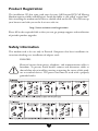
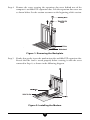
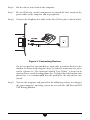
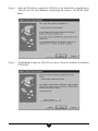
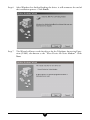
56K Internal PCI
Call Waiting Modem
User's Manual
Table Of Contents
Introduction ........................................................................................... 3
Contacting Actiontec Customer Support ............................................ 3
Product Registration ............................................................................. 4
Safety Information ................................................................................. 4
Product Features ................................................................................... 6
Installing the Modem ............................................................................. 7
Hardware Installation ..................................................................................... 7
Device Driver Installation and Configuration .................................... 10
Configuring Windows 95 .............................................................................. 10
Configuring Windows 95 OSR2 ................................................................... 12
Configuring Windows 98 .............................................................................. 15
Configuring Windows NT 4.0 ....................................................................... 21
Configuring DOS and Windows 3.1X ........................................................... 25
Windows 3.1X .............................................................................................. 27
Configuring OS/2 WARP .............................................................................. 28
Configuring UnixWare .................................................................................. 30
Configuring the Modem For Linux (Verified for Red Hat 5.2 and 6.0) ......... 31
Changing the Call Waiting Settings ............................................................. 37
Configuring Your Modem’s Country Code .................................................... 41
Installing Communications Software ................................................. 42
Using the Modem’s Voice Features ............................................................. 42
The Call Waiting Feature ..................................................................... 44
Using The Call Waiting Control Utility ................................................ 45
AT Commands Affecting ITU-T V.90 Operation .................................. 47
Examples ..................................................................................................... 48
Help and Service Information ............................................................. 49
General Troubleshooting Tips ...................................................................... 49
Reconfiguring a Windows Dial-Up Networking Connection ........................ 51
Notices ................................................................................................. 52
Proprietary Notice and Disclaimer
Unless otherwise noted, this document and the information herein disclosed are proprietary to Actiontec Electronics, Inc. Any person or entity to whom this document is furnished or who otherwise has possession thereof, by acceptance agrees that it will not be
copied or reproduced in whole or in part, nor used in any manner except to meet the
purposes for which it was delivered.
The information in this document is subject to change without notice and should not be
construed as a commitment by Actiontec. Although Actiontec will make every effort to
inform users of substantive errors, Actiontec disclaims all liability for any loss or damage
resulting from the use of this document or any hardware or software described herein,
including without limitation contingent, special or incidental liability.
PC is a trademark of IBM Corporation. MS-DOS, Windows 3.10, Windows 3.11, Windows 95 and Windows NT are trademarks of
Microsoft, Inc., K56Flex is a trademark of Lucent Technologies, Inc. and Rockwell International.
2
Introduction
Thank you for purchasing the Actiontec 56K Internal PCI Call Waiting Modem. The
use of a PCI bus interface reflects the current technology standard in the PC industry. You only need to have one open PCI slot and an available IRQ for easy, trouble
free installation of your new modem. This means no more problems with ISA slots
that are already in use or with new motherboard designs that have only one ISA slot.
The Call Waiting feature of this modem allows you to be surfing the Web and receive
notification of an incoming call. Now you will not have to miss that call. When a call
comes in while the modem is using the line, the modem will ring, just like your
phone would have normally. You can pick up the phone to quickly screen the incoming call. This suspends your internet connection, rather than ending it. You can then
either stay on the phone talking or hang up to get back to surfing the Web. (Requires
that Call Waiting Service is available in your area and purchased by you from your
phone company.)
The innovative Actiontec 56K PCI Call Waiting Modem is also controller based.
This means full compatibility with all common PC Operating Systems such as DOS,
OS/2, UNIX, LINUX, and all versions of Windows.
Contacting Actiontec Customer Support
Actiontec Electronics prides itself on making high-quality, durable, high-performance
products. If you should need assistance, the Actiontec Technical Support Department
is available from 7:00 AM to 7:00 PM Pacific Coast Time, Monday through Friday
to provide professional support.
Actiontec Electronics, Inc.
Technical Support
760 N. Mary Avenue
Sunnyvale, CA 94086
Phone: 408-752-7714 (choose option 7)
Fax:
408-732-0097
BBS:
408-732-0112
Email:[email protected]
New drivers are released as need arises to insure maximum compatibility and operation of your new 56K PCI Call Waiting Modem. Find out about these and other new
Actiontec products at the Actiontec web site:
http://www.actiontec.com
3
Product Registration
The installation CD that came with your Actiontec 56K Internal PCI Call Waiting
Modem contains a folder called Register. Inside this folder is a file called “register.htm”.
After installing the modem and its drivers, double-click on this file. This will start up
your browser and take you to the Actiontec web site:
http://www.actiontec.com/registration
Please fill in the required fields so that you can get prompt support and notification
of periodic product upgrades.
Safety Information
This modem card is for use only in Personal Computers that have installation instructions detailing user installation of adapter cards.
DANGER:
Electrical current from power, telephone, and communication cables is
hazardous. To prevent shock hazard, connect and disconnect cables as
shown below when installing, moving or opening the covers of this product or attached devices. The power cord must be used with a properly
grounded outlet.
4
CAUTION:
To avoid shock hazard:
The power cord must be connected to a properly wired and earthed receptacle.
Any equipment to which this product will be attached must also be connected to properly wired receptacles.
Do not connect or disconnect any cables or perform installation, maintenance, or reconfiguration of this product during an electrical storm.
When using your telephone equipment basic safety precautions should
always be followed to reduce the risk of fire, electrical shock, and injury
to persons, including the following:
Never install telephone jacks in wet locations unless the jack is specifically designed for wet locations.
Never touch uninsulated telephone wires or terminals unless the telephone line has been disconnected at the network interface.
Use caution when installing or modifying telephone lines.
Avoid using a telephone (other than a cordless type) during an electrical
storm. There may be a remote risk of electrical shock from lightning.
Do not use the telephone to report a gas leak in the vicinity of the leak.
Do not connect your modem to a digital PBX (switchboard) system,
because you may damage the modem. Modems are designed to function
with analog telephone lines, such as residential lines.
Do not connect your modem to an ISDN line. In some areas, ISDN
(digital) lines are being provided for residences and businesses. These
lines may damage the modem.
Please note that this modem is fully compatible with analog telephone
lines that are connected to a Digital Exchange. A Digital Exchange is
used in some areas to supply analog lines to homes and businesses.
5
Product Features
The Actiontec 56K Internal PCI Call Waiting Modem contained in
this package has the following features.
•
Conforms to the ITU-T V.90 specification with auto-negotiation of V.90, V.34,
V.32bis, V.32, V.23, V.22bis, V.22, V.21, Bell 212A, and Bell 103 protocols.
•
Supports Group 3: class 1 fax protocols.
•
V.42bis and MNP 5 data compression. MNP2 - MNP4, V.42, and LAPM error
correction.
•
Modem does not rely on the host CPU to perform any internal functions. It is
completely controller-based for use with the the widest range of supported
operating systems:
DOS
Windows (3.1x, 95, 98, and NT)
OS/2
UNIX
Linux
•
Call Waiting.
6
Installing the Modem
System Preparation
Before you begin the installation of your 56K Internal PCI Call Waiting Modem, all
currently installed modems should be removed. This will help prevent hardware conflicts between the new modem and any previously installed modems.
For Windows 95/98/NT
Before you physically remove the old modem, remove it from the list in the Modem
Properties Control Panel.On the taskbar, click Start. On the Start menu, click Settings then click Control Panel and double-click the Modems icon. This will bringup the Modems Properties screen. Find your old modem listed in the General window of Modems Properties. Click once to highlight the modem and then click the
Remove button. Click OK when done. Shutdown Windows, turn off the computer,
and remove the old modem.
For DOS, Windows 3.1, OS/2 Warp, UnixWare, and Linux
There are no special system preparation procedures required for these operating systems. Be sure that the power is off before removing your old modem or installing the
56K PCI Internal Call Waiting Modem.
Hardware Installation
Caution:
Always discharge static electricity before handling your modem. You may discharge static
electricity by touching a grounded metal structure or by using any commercially available
grounding strap.
Make sure the expansion slot type is PCI, which has a smaller slot to fit the PCI modem card.
If you are not familiar with computers or computer hardware or you cannot tell the difference between an ISA slot or PCI slot, obtain the help of someone who has a thorough understanding of computers. You will severely damage your computer if you install the modem in
the wrong slot.
The position of the expansion slots in your computer may differ from the illustrations shown.
Step 1
Turn off the computer and all peripheral devices connected to it.
Step 2
Unplug the computer power cord from the wall outlet.
Step 3
Remove the computer’s cover. Refer to your computer’s owner’s manual for
instructions.
7
Step 4
Remove the screw securing the expansion slot cover behind one of the
computer’s available PCI expansion slots. Lift the expansion slot cover out
as shown below. See the caution statement at the beginning of this section.
Figure 1: Removing the Backplate
Step 5
Firmly, but gently, insert the modem into the available PCI expansion slot.
Ensure that the card is seated properly before securing it with the screw
removed in Step 4, as shown in the following diagram.
Figure 2: Installing the Modem
8
Step 6
Put the chassis cover back on the computer.
Step 7
Be sure all of your system’s components are turned off, then reconnect the
power cables to the computer and its peripherals.
Step 8
Connect the telephone line cable to the Line (Telco) jack as shown below.
Figure 3: Connecting Devices
On the rear panel of your modem are input jacks to connect devices to the
modem. As shown in the diagram, there are jacks for connection to a phone
and to a phone line. The connector labeled “Line (Telco)” is meant to be
connected to a standard analog phone line. To help reduce the load on your
phone line, it is recommended that the modem be the only device connected.
Step 9
Turn on the computer and proceed to the following sections to configure
the your computer’s operating system for use with the 56K Internal PCI
Call Waiting Modem.
9
Device Driver Installation and Configuration
Configuring Windows 95
Step 1
After you have installed the modem into your machine, turn on the power
and allow the system to boot normally.
Step 2
After Windows 95 loads, it will detect new hardware. The modem will be
identified as a “PCI Card”. Make sure the option “Driver from disk provided by hardware manufacturer” is selected, then click the OK button.
Step 3
Windows will prompt you to insert the modem’s installation CD-ROM.
Check the drive path for the correct drive letter. It may be necessary to
change the drive letter to that of the CD-ROM drive. Insert the installation
CD-ROM into the computer’s CD-ROM drive, wait ten seconds so that
the CD-ROM drive can read the disc, then click OK.
Step 4
Windows will find the driver on the installation diskette and finish the
installation process.
10
Step 5
Next Windows detects a “Wave Device for Voice Modem” and displays the
dialog box shown below. Make sure the option “Driver from disk provided
by hardware manufacturer” is selected, then click the OK button.
Step 6
Next, verify that the modem has been properly installed. On the windows
taskbar, click Start. On the Start menu, click Settings, then click Control
Panel. In Control Panel, double-click the Modems icon. The Modems Properties dialog box will appear. Click the Diagnostics tab. Click the COM
Port icon next to the Call Waiting modem to select it, then click More Info.
The “ATI” responses should be listed. That this information has been displayed means the modem has been correctly installed and is functioning.
Step 7
Turn to the section titled “Configuring Your Modem’s Country Code” for
instructions on how to configure the modem to use the Public Switched
Telephone Network (PSTN) of your country.
11
Configuring Windows 95 OSR2
Step 1
After you have installed the modem into your machine, turn on the power
and allow the system to boot normally.
Step 2
Windows 95 will start the Update Device Driver Wizard and immediately
identify the modem as a “PCI Communications Device”. Check the drive
path for the correct drive letter. It may be necessary to change the drive
letter to that of the CD-ROM drive. Insert the modem’s installation CDROM into your computer’s CD-ROM drive. Wait about 10 seconds, so
that the CD-ROM can be read by your system, then click the Next button.
Step 3
At the next screen, Windows will ask if you want to use the driver for the
“56K PCI Call Waiting Modem.” Click Finish. Windows will complete the
installation of the modem.
12
Step 4
After the Wizard has copied the .INF files to the hard disk, it should detect
“Wave Device for Voice Modem” and prompt for its driver CD-ROM. Click
Next.
Step 5
Click Finish to copy the Wave Device driver from the modems installation
CD-ROM.
13
Step 6
Next, verify that the modem has been properly installed. On the windows
taskbar, click Start. On the Start menu, click Settings, then click Control
Panel. In Control Panel, double-click the Modems icon. The Modems Properties dialog box will appear. Click the Diagnostics tab. Click the COM
Port icon next to the Call Waiting modem to select it, then click More Info.
The “ATI” responses should be listed. Compare them with the illustration
below. That this information has been displayed means the modem has
been correctly installed and is functioning.
Step 7
Turn to the section titled “Configuring Your Modem’s Country Code” for
instructions on how to configure the modem to use the Public Switched
Telephone Network (PSTN) of your country.
14
Configuring Windows 98
Step 1
After you have installed the modem into your machine, turn on the power
and allow the system to boot normally.
Step 2
Windows 98 will immediately display the Add New Hardware Wizard and
identify the modem as a “PCI Communications Device”. Click the Next
button.
Step 3
At the next screen, make sure the option “Search for the best driver for your
device” is selected, then click Next.
15
Step 4
Next the wizard will ask which drives or folders it should search for the
drivers. Click to select the CD-ROM drive. A check mark will appear in the
appropriate box. Make sure that all the other options are deselected, clicking them to deselect, if necessary. Insert the modem’s installation CD-ROM.
Wait about 10 seconds, so that the CD-ROM drive can read the disc, and
click Next.
Note:
After inserting the CD-ROM, it is important with some systems to wait a
few seconds before clicking Next. Otherwise, the Wizard may report that it
was unable to find the drivers. If this is the case, click Back and then click
Next, repeating this process until the CD-ROM drive has read the CDROM and Windows has found the drivers, displaying the dialog box shown
in step 5.
Step 5
Windows 98 will find the driver on the CD-ROM and identify the modem
as an “Actiontec 56K PCI Call Waiting Modem.” Click Next.
16
Step 6
After Windows has finished loading the driver, it will announce the end of
the installation process. Click Finish.
Step 7
The Wizard will now search for drivers for the Telephone Answering Functions (TAM), also known as the “Wave Device for Voice Modem”. Click
Next.
17
Step 8
At the next dialog box, make sure that “Search for the best driver for your
device. (Recommended)” is selected, and then click Next.
Step 9
Next the wizard will ask which drives or folders it should search for the
driver files. Click to select CD-ROM drive. A check mark will appear in the
appropriate box. Make sure that all the other options are deselected, clicking them to deselect, if necessary. When finished, Click Next.
18
Step 10 The wizard will find the correct driver on the CD-ROM and announce it is
ready to install. Click Next.
Step 11 After Windows has finished copying the drivers to where they belong in
your system, it will announce the end of the installation process. Click the
Finish button.
19
Step 12 Next, verify that the modem has been properly installed. On the windows
taskbar, click Start. On the Start menu, click Settings, then click Control
Panel. In Control Panel, double-click the Modems icon. The Modems Properties dialog box will appear. Click the Diagnostics tab. Click the COM
Port icon next to the Call Waiting modem to select it, then click More Info.
The “ATI” responses should be listed. Compare them with the illustration
below. That this information has been displayed means the modem has
been correctly installed and is functioning.
Step 13 Turn to the section titled “Configuring Your Modem’s Country Code” for
instructions on how to configure the modem to use the Public Switched
Telephone Network (PSTN) of your country.
20
Configuring Windows NT 4.0
Step 1
After you have installed the modem into your machine, turn on the power
and allow the system to boot normally.
Step 2
Insert the installation CD-ROM into the computer’s CD-ROM drive. On
the taskbar, click Start. On the start menu, click Run. Type:
x:\drivers\pciven\winnt\setupnt.exe
where x is the letter of your CD-ROM drive, and click the OK button.
Step 3
After the program has finished unpacking the driver and setting it up, a
window like the one below will be displayed.
Step 4
Remove the installation CD-ROM and click Finish to restart your computer.
Step 5
After Windows NT restarts, on the Start menu, click Settings, click Control Panel, then double-click the Modems icon.
21
Step 6
When the Install New Modem dialog box appears, allow Windows NT to
detect your modem. Click Next.
Step 7
Windows NT will detect the modem as a “Standard Modem”. Click Change.
22
Step 8
Insert the modem’s installation CD-ROM into the computer’s CD-ROM
drive. Click Have Disk.
Step 9
A new window will appear with another list of modems, one of which will
be the Actiontec 56K Internal PCI Call Waiting Modem. Select it and click
OK. At the next dialog box, click Next.
23
Step 10 Windows NT will complete the installation of the modem. Remove the
modem’s installation CD from the CD-ROM drive. Click Finish.
Step 11 If you wish to use the modem to dial a Windows NT Remote Access Server
or wish to connect to the Internet, you will need to configure Dial-Up
Networking. On the Windows taskbar, click Start. On the Start menu,
click Settings, then click Control Panel. In Control Panel, double-click the
Network icon. (If the networking components of Windows NT 4.0 have
not been installed, perform this process before attempting to configure Remote Access Services.) Click the Services folder and select Remote Access
Service.
Note:
If the Remote Access Service option is not listed, click the Add button.
Scroll-down the menu and select Remote Access Service. Click the OK
button. Windows NT may ask for it’s own installation CD-ROM for some
files. Insert as required. After you have installed Remote Access Services,
add the appropriate protocols as directed (i.e. TCP/IP for Internet Access).
Step 12 (Continued from Step 11) At the Remote Access Setup dialog box, click
Add. Select the modem as the RAS Device and then click the OK button.
Step 13 Click Continue to finish the installation.
Step 14 After Windows NT has completed the binding process, allow Windows to
shut down and restart the computer.
Step 15 Turn to the section titled “Configuring Your Modem’s Country Code” for
instructions on how to configure the modem to use the Public Switched
Telephone Network (PSTN) of your country.
24
Configuring DOS and Windows 3.1X
Note:
Not all communications programs are supported under DOS due to PCI
IRQ requirements. Unless your communication program can support IRQ
9 or above and can address nonstandard COM port addresses, it may not
be able to support this modem.
Step 1
After you have installed the modem into your machine, turn on the power
and allow the system to boot normally.
Step 2
After the system has loaded, insert the installation diskette into the computer’s
floppy disk drive. At the command prompt, type:
A:PMDMCFG.EXE
and press ENTER.
Step 3
A message similar to the one shown below will be displayed. (Actual values
will change from system to system)
Found V.90 PCI Data/Fax Modem
----------------------------I/O Port:
FC00
IRQ#:
11
Step 4
Write down the IRQ Number and Base I/O Address that have been assigned to the modem. If the default Base I/O Address is greater than 7900,
you will need to add a statement to your “AUTOEXE.BAT” file to preset
this address to a specific value—go to Step 5.
Note:
If your default address is below 7900, skip to Step 6. Before you proceed,
copy the PMDMCFG.EXE file to the root directory of your default hard
drive, usually the C drive.
Step 5
If the default Base I/O Address in Step 3 was greater than 7900, add the
following statement your AUTOEXEC.BAT file:
C:\PMDMCFG
/P7900
This will cause the Base I/O Address of the modem to be preset to a specific
value.
25
Step 6
Use the default I/O Port Address (or 7900 if you modified your autoexec.bat
file) and the IRQ Number you recorded in Step 4 to set up your DOS
applications. You may also need to assign an unused COM port to the
modem. The preferred COM port setting is COM 4.
Step 7
After you nave set up your applications to use the modem, you will need to
issue an AT command to configure the modem to use the Public Switched
Telephone Network (PSTN) of your country. The modem can be configured for Canada, Japan, and the United States.
To configure the modem’s country setting, open a terminal program. At the
command prompt, type:
at
and press ENTER. The response should be “OK”. Now type one of the
following commands depending on the country where the modem will be
operated.
Canada:
Japan:
United States:
at%T19,0,1
at%T19,0,10
at%T19,0,19
After typing the appropriate command, press ENTER. If the command
was properly entered, the response will be “OK”. If you recieve a response
of “ERROR” check the command above a second time, and enter it again.
After the command has been entered and accepted, the modem will default
to this setting every time you turn on the system. To find your current
country setting, issue the command
ati9
The response will indicate your current country setting (Canada, Japan, or
North America).
Continue with the next section, “Configuring Windows 3.1X,” if installing
in that operating system. Otherwise, your DOS installation is complete.
26
Windows 3.1X
Step 8
After you have modified your AUTOEXEC.BAT file to preset the I/O port
address and have obtained the modem’s IRQ Number by running the DOS
PMDMCFG.EXE program, load Windows 3.1X.
Step 9
In Program Manager, double-click Main. In Main, double-click Control
Panel and in Control Panel, double-click Ports. In the Ports dialog box,
select an unused COM port (the preferred setting is COM 4) and click
Settings, then click Advanced.
Step 10 Change the value for the Base I/O Address and the IRQ to the same value
you wrote down in Step 4. If you modified your AUTOEXEC.BAT file in
Step 5, use 7900 as your Base I/O Address. Click OK when done.
Step 11 Windows will prompt you to reboot. Remove the diskette from the floppy
disk drive and then click Yes.
Step 12 After the system reboots, restart Windows 3.1X and configure your
communicatons software to use the same COM port you assigned to the
modem in Step 10. Your modem should now be properly installed and
ready for use.
Step 13 If you did not set the country code command during the DOS installation,
turn to the section titled “Configuring Your Modem’s Country Code” for
instructions on how to configure the modem to use the Public Switched
Telephone Network (PSTN) of your country.
27
Configuring OS/2 WARP
Note:
If your computer system uses a Phoenix BIOS, you must disable PnP OS
support for the modem to be recognized in OS/2. See your computer users
manual for information on accessing and changing your system BIOS settings.
Step 1
After you have installed the modem card, turn on your computer. While
OS/2 boots, watch for the OS/2 logo in the upper left corner of the screen.
When you see this logo, press ALT+F1 to get the Startup Menu. Press F5 at
the menu to perform Full Hardware Detection.
Step 2
After OS/2 boots, insert the modem’s installation CD-ROM into the
computer’s CD-ROM drive.
Step 3
Click the PCDOS button on the OS/2 screen. At the command prompt
type:
A:PMDMCFG
and press ENTER. A message similar to the one shown below will be displayed. (Actual values will change from system to system.)
Found V.90 PCI Data/Fax Modem
----------------------------I/O Port:
FC00
IRQ#:
11
Record these values. They will be needed in Step 7 when you modify your
config.sys file and latter when you configure your applications.
Step 4
Be sure the modem’s installation CD-ROM is still in the CD-ROM drive.
Now type the following, as one continuous command (in place of the lowercase x, type the drive letter of your CD-ROM drive):
COPY x:\OS2\COM.SYS C:\OS2\BOOT\COM.SYS
and press ENTER.
Note:
This will replace your resident COM.SYS file with a new version. OS/2
will not prompt you to overwrite the existing file. Check that the path statements are correct before you press ENTER.
28
Step 5
Remove the Installation CD-ROM from the CD-ROM drive..
Step 6
Click the OS/2 command prompt button on the OS/2 screen. At the command prompt type:
e CONFIG.SYS
press ENTER.
Step 7
You will need to modify your CONFIG.SYS file. Find the entry for
COM.SYS (It should be just after the KEYBOARD.DCP statement and
before the VIOTBL.DCP statement. If it is not, arrange the order of the
statements so that this is the case.) If there is no COM.SYS or VCOM.SYS
statement, add these to your CONFIG.SYS file (see the example for the
proper syntax). Be sure these statements are between the KEYBOARD.DCP
and VIOTBL.DCP entries.
Modify the COM.SYS statement using the values you recorded in Step 4:
DEVICE=C:\OS2\BOOT\COM.SYS (x,yyyy,n)
DEVICE=C:\OS2\MDOS\VCOM.SYS
Where: x is either 1, 2, 3, or 4 (COM4 is recommended)
yyyy is the I/O Port Address ( in Hexadecimal) of the modem
n is the IRQ number of the modem
Example:
DEVICE=C:\OS2\BOOT\COM.SYS (4,F400,11)
DEVICE=C:\OS2\MDOS\VCOM.SYS
Step 8
Save the new CONFIG.SYS file. Check that the installation diskette has
been removed from the floppy disk drive and then reboot the system.
Step 9
You will now be able to use your communications programs at the COM
Port you assigned in Step 7.
29
Configuring UnixWare
Note:
These installation instructions are for UnixWare 2.1. Installation on other
versions of Unix may be different. Please consult your operating system
manual or help text for instructions regarding installation of a serial modem.
Step 1
After you have installed the modem into your machine, turn on the power
and allow the system to boot normally. Log in to Unix as “Desktop User”.
Step 2
Go to Administrative_Tools-Hardware_Setup. This will require the root
password.
Step 3
In the Hardware_Setup main menu, choose Hardware Device Configuration and press ENTER.
Step 4
Under the Device Name column, try to locate all of the “Unknown Devices”. For each unknown device you find, move the cursor to each row and
press F6 for information. Look for the item “Board ID”. You will be looking for a board with ID “0x11c10480”.
Step 5
Once you find the board, press ENTER to return to the previous screen.
Now use the tab key to move the cursor to the Device Name field for that
board. Press F2 to bring up the list of choices.
Step 6
In the Device Name Choices screen, choose COM port or asyn, then press
ENTER to go back to the Hardware Devices Configuration screen.
Step 7
Press F10 to return to the Main Menu. Now choose Apply Changes & Exit
DCU.
Step 8
Reboot the computer. Turn to the section titled “Configuring Your Modem’s
Country Code” for instructions on how to configure the modem to use the
Public Switched Telephone Network (PSTN) of your country.
Note:
If you cannot find a board with the proper ID, then exit UnixWare and
power down. Check that the PCI Modem is correctly seated in the PCI slot.
Remove and reseat the card if required.
To find out which COM Port is assigned to the modem, choose Software
Device Driver Selections from the Main Menu. Now choose Communications Cards and press F6 to get the information for the asyn driver.
To test the modem, UnixWare provides a utility that can be used as a terminal program. To use this program, log in as “root” or get an x-terminal “su
root”. Then run /usr/lib/uucp/modem <device> <baudrate>.
30
Configuring the Modem For Linux (Verified for Red Hat 5.2 and 6.0)
Note:
The kernel should have serial support and you should have some communications program, such as minicom, installed.
The modem will come configured to work on a COM port referred to by the files /
dev/ttySx or /dev/cuax. If these files do not exist in your /dev directory, they can be
added as follows.
Step 1
As root, type:
cd dev
and press ENTER. Next, type:
# ./MAKEDEV ttySx
Where x is the COM port. This will create the appropriate files.
Note:
There is no MAKEDEV in OpenLinux. In this case, the commands will be
as follows (as root):
mknod /dev/ttyS4 c 4 68
and press ENTER. Next, type:
mknod /dev/cua4 c 5 68
and press ENTER.
Note:
Versions of Linux with the 2.2x kernel or newer versions of Linux, the /
dev/cua4 device is obsolete.
Step 2
Many programs use the /dev/modem symbolic link to refer to the modem.
To create this link, type:
ln -s /dev/ttyS4 /dev/modem
and press ENTER. Typing the following:
chmod 666 /dev/ttySx
pressing ENTER, then typing
31
chmod 666 /dev/modem
instead (where x is the COM port) will let all users access the modem.
Step 3
Determine the port and IRQ assigned to the device by typing:
cat /proc/pci
and pressing ENTER. The following is an example of a possible outcome:
5.
Non-prefetchable 32 bit memory at 0x00000000.
Bus 0, device 17, function 0:
Communication controller: Unknown vendor Unknown device (rev 0).
Vendor id=11c1. Device id=480
Medium devsel. Fast back-to-back capable. IRQ 11.
Master Capable
No Bursts
Min Gnt=252.Max Lat=14
Non-prefetchable 32 bit memory at 0xe4000000.
I/O at 0x6400.
I/O at 0x6800.
I/O at 0x6c00.
Step 4
Write down the first input/output range and IRQ. In this case, the I/O
address is 0x6400 and the IRQ is 11. Type
setserial /dev/modem uart 16550A port 0x6400 irq 11
(The IRQ and port may vary depending on the results from step 3.)
Step 5
Try out the settings in a program such as minicom.
Step 6
If the settings work, then add the line above in the /etc/rc.d/rc.local file.
This way, the modem will be set properly each time Linux is booted.
Step 7
To set Linux to configure the modem on boot-up, there are several options.
One method is going to the /etc/rc.d/ directory, and, using an editing
program such as jed, edit the rc.local file, inserting
setserial /dev/modem uart 16550A prot 0x6400 irq 11
as the last line.
32
Setting up and using PPP
Note:
A PPP package (such as ppp-2.3.5-1.i386.rpm) can be found on the installation CD-ROM or from ftp://ftp.redhat.com. The kernel should also have
TCP/IP support enabled.
To be able to set up and use PPP, you must have an Internet Service Provider (ISP).
The following information from the ISP is needed:
•
User name and password
•
Phone number(s) used to dial into the ISP’s modems
•
The IP address assigned by the ISP (this is not necessary if the ISP dynamically
assigns an IP address each time you connect)
•
the IP address of the ISP’s Domain Name Server. (Many ISPs have more than
one server. You need at least one in order to translate a URL such as
www.actiontec.com into an IP address, although you can still set up PPP without
it.)
There are many tools that make setting up PPP easier. This section explains some
basic ways to set up PPP.
Setting Up and Using PPP (Minimal Setup)
This section explains one way to set up a PPP connection from the command line. It
does not go into tools such as linuxconf or KPPP.
Step 1
The documentation for PPP comes with some sample dial-in scripts. They
are located under /usr/doc/ppp-2.3.5/scripts. Copy ppp-on, ppp-on-dial
and ppp-off into the /etc/ppp directory, which should have also been created when PPP was installed. To copy the files, type the following:
cp /usr/doc/ppp-2.3.5/scripts/ppp-* /etc/ppp
and press ENTER. This must be done at root. ppp-on-dialer is a script
which calls the chat program, which communicates with the modem on
making a connection.
Step 2
Open up ppp-on in a text editor and make the changes to the parameters at
the top of the file. Also, at the bottom of the file, change /dev/ttyS0 to /dev/
ttyS4 and 38400 to 115200. Save and close the file.
33
Step 3
Open up ppp-on-dialer in a text editor and change the setting after
TIMEOUT (probably 30) to 60. If this script is to be accessible to other
users besides root, change the line which reads:
exec chat -v
to include the path for the chat program (usually /usr/sbin/chat) as follows:
exec /usr/sbin/chat -v
Then save and close the file.
Step 4
Open up /etc/ppp/options. Make sure there is a line that says “lock” in it.
This prevents other processes from accessing the modem while it is in use.
If it is not there, add it in and save and close the file.
Step 5
Set the permissions on the scripts to be executable by typing
chmod +x ppp-o*
and pressing ENTER. Since the password is stored unencrypted in ppp-on,
it is a good idea to set permissions on that file to 711 (read/write/execute for
owner and execute-only for everyone else), and change owner and group to
root by typing (as root):
chmod 711 ppp-on
chown root ppp-on
chgrp root ppp-on
pressing ENTER after the last argument of each command.
Step 6
Open up the /etc/resolv.conf file. In it, enter the IP addresses of the ISP’s
DNS’s as follows:
nameserver x.x.x.x
where x.x.x.x is the IP address of the DNS. Enter each one on its own
line in the same format.
Step 7
To test the connection, run /etc/ppp/ppp-on by typing it (full path
also) at the prompt. The prompt should return, and the modem should
start dialing soon.
34
Step 8
Run ifconfig. You should see a listing for ppp0 if the connection was
successful.
Step 9
To disconnect, run /etc/ppp/ppp-off
Step 10 If this configuration works, you can make a symbolic link to your ppp-on
and ppp-off scripts by typing:
ln -s /etc/ppp/ppp-on /usr/bin/ppp-on
pressing ENTER, then typing;
ln -s /etc/ppp/ppp-off /usr/bin/ppp-off
and pressing ENTER.
Using the GNOME Dialer Applet
The GNOME dialer applet uses the /etc/ppp/ppp-on script to connect and
the /etc/ppp/ppp-off script to disconnect. Be sure those are set up as shown
in the previous section before using the dialer applet.
Step 1
Start the applet by right-clicking on the panel and select the Add Applet
menu. The dialer applet should be in the Networking sub-menu.
Step 2
To connect, click Play/Pause.
Step 3
To disconnect, click Stop.
Configuring And Using kppp
The KPPP package must be installed prior to using these instructions. The file can
either be obtained as part of the kde-applications package or from kdenetwork-ppp*.rpm
Step 1
Open up KPPP from the KDE menu. It is most likely located under the
Internet subfolder.
Step 2
When KPPP starts up, click Setup.
35
Step 3
Before setting up individual PPP accounts, the modem itself needs to be
configured. Click on the Device tab, and verify that the modem device
refers to /dev/modem (kppp does not have an entry for /dev/ttyS4,
so /dev/modem is used instead). If you do not have /dev/modem set up,
refer to the section labeled “Configuring the Modem.” Also, set the connection speed to 115200.
Step 4
Go to the Modem tab. Click Modem Commands and change the last setting under Volume to M1L3. Click OK. Use the slider to adjust the volume
of the modem, if desired. The modem speaker is off when the slider is all
the way to the left. Now click Query Modem. A window should come up
and return the modem’s ATI strings, if the modem was configured properly.
Close this window after viewing it.
Step 5
Now, back in the KPPP configuration window, go to the Accounts tab and
click New. Enter a name for the connection, your ISP’s phone number, and
any other information provided by the ISP to make this connection (except
the user name and password).
Note:
Selecting “Save Password” as the password will cause the password to be saved
into a plain text file.
Click OK when done.
Step 6
Click OK to close the kppp configuration window. In the kppp main window, enter the user name and password for the connection. Click Connect
to dial.
Step 7
When the call is completed, the dialer window will minimize itself. To disconnect, restore the dialer window and click Disconnect.
Setting Up and Using The linuxconf Dialer
Red Hat’s linuxconf utility can only be run by root or users with superuser privileges.
Step 1
Start up linuxconf by typing
linuxconf
at the prompt, or, if root, selecting it from the Control Panel.
Step 2
The menu item for PPP is under the headings Config, Networking, Client
Tasks. Select it and click add to make a new profile.
36
Step 3
Choose PPP and click Accept.
Step 4
Enter the ISP’s phone number, your user name and password. Note that
this will store the password will be stored in an unencrypted text file. If
security is a concern, do not enter the password until actually dialing.
Step 5
Click Accept to save the new record.
Step 6
To dial, select the connection from the list of connections. A new Interface
tab will appear. If you did not enter your password when setting up your
connection, go to the Connection tab and enter the password. When exiting the dialer, click Cancel to exit so that your password will not be saved.
Step 7
Disconnecting is similar: Start up linuxconf (if you closed it), go to the
PPP/SLIP/PLIP menu item, select your connection and click disconnect.
Some General Tips
•
The permissions on pppd have to be changed to suid root if other users besides
root are to be able to make PPP connections. This is the same with KPPP. An
alternative is to create a “modem” group and give read/write permissions to that
group. Then add the users who are allowed to use the modem to that group.
•
A secure way to start up PPP is to make a login specifically for PPP access whose
shell is a call to pppd.
•
Starting pppd with the “debug” option prints some informative information to
the screen
•
The KPPP FAQ provides some good additional troubleshooting tips.
Changing the Call Waiting Settings
The Call Waiting feature on the modem is configured by changing the S10 register.
The options are as follows:
S10 Value
0
Means
Call waiting feature is enabled. The modem will ring
when a call comes in (default)
1
Call waiting feature is disabled on the modem. The modem will not ring when a call comes in.
2
Disconnect when a call comes in.
?
Returns the current value of S10
37
Unlike Windows 95/98, there is no set configuration for the modem itself. The modem is regarded as another serial port attached to the computer. Therefore each program must provide its own initialization string when using the modem. Setting the
call waiting feature changing the initialization string (often ATZ, by default) to include a S10=n, where n is one of the settings available above.
With the setcw.tcl program
This utility provides a graphical way to modify the call waiting setting for KPPP,
ppp-on scripts, and linuxconf. It uses tcl/tk, and the user must have wish installed.
Step 1
Run the program by typing:
setcw.tcl
and pressing ENTER.
Step 2
The program will detect if each of those configurations exist and the user
has read/write access to the necessary files. The configurations that exist
will be checked.
Step 3
Change the setting by selecting one of the three radio buttons at the top
and clicking Set.
Step 4
If you get a “Invalid kppprc file” message, it means that the program did
not find an “InitString=” entry in the file. This can be generated by opening up the Modem Commands window from within kppp.
Step 5
Click Exit.
ppp-on Scripts
The change is actually in the /etc/ppp/ppp-on-dialer script. The script has no line
that contains an initialization string, so one needs to be added. The line should go
right before the line that says:
OK
ATDT$TELEPHONE\
An example of what should be added is something like this:
‘’
ATS10=1 \
Be sure to put the \ at the end of the line, since chat takes all of its arguments in one
line. (The \ quotes the invisible carriage-return character.)
38
GNOME dialer applet
The changes need to be made to the ppp-on-dialer script.
KPPP
In the KPPP Configuration window, Modem tab, Modem Commands button, change
the Initialization String field to include the appropriate setting. To manually make
the changes, edit ~/.kde/share/config/kppprc in your home directory. Edit the line
that says:
InitString=ATZ
to include the desired setting for the call waiting feature, for example, to disable call
waiting, change the line to:
InitString=ATS10=1
If this line does not appear, either go into KPPP and open the Modem Commands
window, or type the line in yourself, under the [modem] section of the file.
linuxconf
The initialization string is in the PPP interface screen (it appears when you select
your PPP connection from the list of available connections). Go to the Communications screen and edit the field labeled Modem Init String. To manually change the
call waiting option settings, two files need to be modified:
/etc/sysconfig/network-scripts/chat-pppX
and
/etc/sysconfig/network-scripts/ifcfg-pppX
where pppX refers to the individual ppp record (ppp0, ppp1, etc.). The line to be
changed is right before the dialing occurs. In chat-pppX, the line was originally:
‘’ ‘ATZ’
and comes right before a line that contains the string ATDTXXX-XXXX, where
XXX-XXXX is the phone number you dial to your ISP. In ifcfg-pppX the line
reads:
INITSTRING=”ATZ”
These two files usually only have read/write access by the owner (root).
39
minicom
From within minicom, type CTRL-A O (hold CTRL, press A, let go of both, then
press O) to access the options menu. Select “Modem and dialing” and alter the “Init
String” field. The settings will be saved in /etc/minirc.dfl. Alternatively, you
can start minicom with the -s option. This launches the options menu before initializing the modem.
40
Configuring Your Modem’s Country Code
After following the steps for your operating system and after the system has restarted,
you may need to issue an AT command to configure the modem to use the Public
Switched Telephone Network (PSTN) of your country. The modem can be configured for Canada, Japan, and the United States.
To configure the modem’s country setting, open a terminal program, such as HyperTerminal. At the command prompt, type:
at
Press ENTER. The response should be “OK”. Now type one of the following commands depending on the country where the modem will be operated.
Canada:
Japan:
United States:
at%T19,0,1
at%T19,0,10
at%T19,0,19
After typing the appropriate command, press ENTER. If the command was properly
entered, the response will be “OK”. If you recieve a response of “ERROR” check the
command above a second time, and enter it again. After the command has been
entered and accepted, the modem will default to this setting every time you turn on
the system. To find your current country setting, issue the command
ati9
and press ENTER. The response will indicate your current country setting (Canada,
Japan, or North America).
41
Installing Communications Software
Note:
Some configurations are packaged without communications software. Check
your packaging to see if communications software is included.
If your modem came with a communications software package, it is strongly recommended that you use this software for your modem, rather than a different version of
the software or software from a different vendor. The default installation parameters
in the software that came with this modem have been specially configured to work
with this modem. The Users Guide for this program can be found inside the modem
package. It can be supplied in either soft-bound copy or on CD-ROM (depending
on the model you purchased).
If you wish to use another software package, please be sure that it supports this modem. Most Software Manufacturers have a listing of supported modems on their
websites or BBS’s. Check these sites to see if this model is supported. If you are
unsure or your brand of software supports only a few modems, try selecting “Hayes
Compatible” or “Standard Modem”. This may work in certain cases.
Some software programs allow manual input of parameters. For the users of these
programs, here is a listing of the Data/Fax/Voice Command Standards supported.
Data:
Fax:
Voice:
Init String:
TIA/EIA-602
TIA/EIA-578 for Class 1 Fax
TIA IS-101 support for TAD (Telephone Answering Device)
AT&F&C1&D2W2
TIA IS-101 Commands not supported:
Caller ID
Full Duplex Speakerphone
VoiceView
Note: some programs must be configured to communicate with the modem on the
same COM port and or IRQ setting used by the modem. See “Installing the Modem” for instructions on how to determine your COM Port and IRQ settings.
Using the Modem’s Voice Features
This modem supports TIA IS-101 commands applicable to a Telephone Answering
Device. In order to take advantage of this feature, you will need a Sound Blaster®
compatible sound card equipped with an external microphone and external speakers.
A software application which supports these TAD functions (such as the one supplied with the modem) is also required.
A modem based Telephone Answering Machine works by using a sound card equipped
42
with a microphone to record an outgoing message. This message is stored as a .wav
file which is transferred to the modem by the application program when an incoming
call is detected. The modem’s internal electronics converts the digital information
contained in the .wav file into an audio signal which is then sent over the phone line.
The person calling hears your outgoing message and responds with an incoming
message.
The sequence of recording an incoming message is the reverse of an outgoing message. The modem converts the audio signal into a digital format and sends it to the
application program. The application program then formats and stores the incoming
message as a .wav file. When you play back your stored messages by selecting them
from within the application program, they are sent to the sound card. You then hear
your recorded messages through the sound card’s speakers.
The default parameters of the software which came with your modem have been
specially configured to identify and use your modems voice capabilities. Even if you
have decided to use another third-party application, try your included application
first. This will allow you to test the modem and its voice functions before investing in
an expensive retail software package.
43
The Call Waiting Feature
With the Call Waiting feature from your telephone company and the Actiontec’s Call
Waiting Modem installed, your modem will notify you of an incoming call as you are
surfing the Web. You may pick up the phone that is connected to your modem to
find out who is calling you, and you’ll have a period of time (approximately 7 seconds, depending on your ISP) to hang up the phone and continue surfing.
To Receive an Incoming Call while Online:
Step 1
You will hear a ring every 6 seconds. This will originate from the modem
rather than from the phone, and it will be repeated for 5 rings.
Step 2
To receive the call, pick up the phone that is connected to your modem.
Step 3
Talk to the calling party.
Step 4
If you hang up within approximately 7 seconds (depending on your ISP)
you may continue to surf the Web.
Note:
If after screening the incoming call you wish to quickly finish your online
work and continue talking to the caller, ask the caller to stay on the line.
Hang up the phone, and finish your work. After disconnecting the modem
you can pick up the phone and continue talking to the caller.
Step 5
If you want to talk to the calling party or the time period exceeds the ISP’s
time limit, your Internet access will be automatically disconnected. A Reestablish Connection box will appear for you to easily reconnect to the internet.
To Ignore an Incoming Call
•
Just disregard the audible rings. It will ring 5 times and then will quit.
•
Or, you may pick up the handset and immediately hang up.
44
Note: Use of the Call Waiting feature requires:
•
Actiontec’s Call Waiting Modem
•
Call Waiting Service from your telephone company
•
You are using your Call Waiting Modem.
•
You have a phone connected to the Call Waiting Modem.
•
You do not disable the Call Waiting Service from your telephone company via
the touch-tone sequence of : *70.
Using The Call Waiting Control Utility
The Call Waiting Control Utility software allows you to decide how you want to
mange incoming phone calls while online. It gives you three choices. While you are
online, you can choose to have the modem ring, notifying you of an incoming phone
call. You can also choose to have the modem automatically terminate your Internet
connection upon receipt of a call. Or you can disable Call Waiting altogether.
•
“Enable Call Waiting Ringing (Still Online)”--If you select this option the
modem will ring when you receive an incoming call. With this option selected,
you can pick up the phone, find out who is calling, hang up within approximately
45
7 seconds, and resume surfing the Internet. Or you can ignore the call altogether.
You can also place the caller on hold by hanging up the phone. Then you can
finish your work online, pick up the phone again and continue your conversation.
•
“Automatic Online Disconnection Upon Receipt Of Call”-- By choosing this
option, your incoming calls will have priority over the Internet connection. All
of your household phones will ring when you receive an incoming call. Your link
to the Internet will have been terminated, and anyone in the house may pick up
the phone and speak to the caller.
•
“Disable Call Waiting Notification (Ringing)”-- the effect of this option is similar
to that of the “*70” prefix you can dial to disable call wating. If you choose this
option you will not be notified of incoming phone calls while online, and your
callers will hear a ring, as if you were not home to answer the call.
46
AT Commands Affecting ITU-T V.90 Operation
There are 3 S-registers which support K56flex, V.90, and V.34 connections. The S37
register is used to control the upstream V.34 rate. S38 sets the maximum downstream
speed that the modem attempts to connect. To disable V.90, set S38 to 0. Use the
S109 register to select between K56flex and V.90 protocols.
Use the S109 register to disable 56K connections or to choose between K56flex and
V.90 protocols. The default setting (S109=1) will attempt K56flex and then V.34
depending upon the central site modem being called and your phone line conditions.
S37 (default: 0)
Upstream (V.34) Rate
S37 = 0
S37 = 1
S37 = 2
S37 = 3
S37 = 4
S37 = 5
S37 = 6
S37 = 7
S37 = 8
S37 = 9
S37 = 10
S37 = 11
S37 = 12
S37 = 13
S37 = 14
S37 = 15
S37 = 16
S37 = 17
S37 = 18
S37 = 19
maximum modem speed (default)
reserved
1200 bits/s and 75 bits/s
300 bits/s
reserved
1200 bits/s
2400 bits/s
4800 bits/s
7200 bits/s
9600 bits/s
12000 bits/s
14400 bits/s
16800 bits/s
19200 bits/s
21600 bits/s
24000 bits/s
26400 bits/s
28800 bits/s
31200 bits/s
33600 bits/s
S38 (default: 1)
56K Dial Line Rate
S38 = 0
S38 = 1
S38 = 2
S38 = 3
S38 = 4
S38 = 5
S38 = 6
Disable all 56K connections
autorate - maximum achievable connection (default)
29333 bits / s
30666 bits / s
32000 bits / s
33333 bits / s
34666 bits / s
47
S38 = 7
S38 = 8
S38 = 9
S38 = 10
S38 = 12
S38 = 13
S38 = 14
S38 = 15
S38 = 16
S38 = 17
S38 = 18
S38 = 19
S38 = 20
36000 bits / s
37333 bits / s
38666 bits / s
40000 bits / s
42666 bits / s
44000 bits / s
45333 bits / s
46666 bits / s
48000 bits / s
49333 bits / s
50666 bits / s
52000 bits / s
53333 bits / s
S109 (default: 1)
K56flex and V.90 Selection
S109 = 0
S109 = 1
S109 = 2
Disable all 56K connections
K56flex only, V.90 disabled (default)
V.90 only. K56flex disabled
Examples
at&fs38=0s109=0This will disable all 56K connections
at&fs38=1s109=1s37=14 This will disable V.90 connections. The modem
will try to connect at K56flex rates with the V.34
upstream rate limited to 21.6K bps.
at&fs38=1s109=2This will cause the modem to attempt a V.90 connection
only. If V.90 is not achieved, it will fall back to
V.34 rates.
at&fs38=10s109=2
This will cause the modem to attempt a V.90 connection at 40K bps. It will fall back to slower
speeds if it cannot achieve or maintain this rate.
As a suggested “init string” in your communications program, use:
at&fw2s109=2s38=1s37=14
48
Help and Service Information
General Troubleshooting Tips
Modem is not detected on power-up:
•
Check your system BIOS IRQ assignments and make sure that at least two
interrupts (especially any unused interrupts) have been assigned to the PCI bus.
Go to your system BIOS’s Setup routine and find the Plug-N-Play settings.
These settings can be found within the “Advanced”, “PNP/PCI Configuration”,
or “Plug and Play Configuration” sections depending on the BIOS manufacturer.
Next, verify that at least two IRQs have been set so that the PCI bus has access to
them (some BIOS don’t allow individual selection of interrupts to ISA, Plug-NPlay, or PCI). These settings can be called ICU, ICU/PCI, PCI, or PNP
depending on your BIOS version and manufacturer. Do not set all the interrupts
to “ISA” only or to “Legacy ISA”. Pay attention to the IRQ usage of the other
peripherals in your system. Do not reassign an interrupt that is already in use by
an ISA card to the PCI bus.
•
Turn off the power and unplug the power cord from the system. Check that the
56K PCI Internal Call Waiting Modem is properly inserted into the PCI slot.
Remove the card and reinsert it if necessary.
•
Try inserting the PCI Modem into another PCI slot. The slot you are using may
have a problem. Try all available slots if necessary.
“No dialtone” error:
•
You may have too many devices connected to the phone line. Remove all other
equipment.
•
Your modem may not recognize the dial tone. Use the AT%T19,0,nn command or the Region Selection Program to reconfigure the modem’s Country
Setting.
Communications software does not work:
•
Some communication software packages need to be configured to the same COM
Port and/ or IRQ as the modem.
Nothing appears on the screen when I type In terminal mode:
•
Issue the command ATE1 to the modem to enable command echo. This will let
you see what you type.
49
Can’t Connect at 56K Rates:
Note:
Current FCC regulations limit your maximum connection rate to 53Kbits
per sec.
•
The number you are calling may not support V.90 or K56flex protocols. Some
Internet service providers have special numbers that you must call to connect at
56K rates. Contact your service provider and ask if the number you are calling
supports V.90 or K56flex connections to their service.
•
In Windows 95/98/NT, check the maximum speed setting in the Modem
Properties window. On the Start menu, click Settings then click Control Panel
and double-click the Modems icon. Highlight your modem by clicking once on
the icon next to the modem and then click the Properties button. Select the
General tab and look at the setting in the Maximum speed box. Make sure this
is set to 115200.
•
You may have too many telephone devices connected to the phone line. To help
your modem achieve the best connection possible, remove all extra devices
connected to the telephone line when the modem is in use. This includes extension
phones, answering machines, and especially cordless phone recharger bases.
“Open COM Port” Error Message in Windows 95/98/NT:
•
You may have Dial-Up Networking connections configured for an old modem
on the same COM Port. Reconfigure these to point to the PCI Modem. See the
next section for instructions.
•
If the Dial-Up Networking connections have all been reconfigured and the error
persists, some other program running in the background is accessing the modem.
Close any applications that are open on the TaskBar or that have icons visible in
the sys-tray, including fax software, dialers, and Internet browsers. Any program
that can address a COM Port or uses a modem can cause this error.
50
Reconfiguring a Windows Dial-Up Networking Connection
When you attempt to check your modem after configuration, or to configure a DialUp Networking connection, Windows may issue a “COM Port open” error message.
This means that previously installed modem configurations using the same COM
Port as the Actiontec 56K PCI Internal Call Waiting Modem may be interfering
with its operation. This interference is most likely due to the presence of an old DialUp Networking configuration. The problem is easily corrected by following these
simple steps.
Step 1
Double-click the My Computer icon located on the Windows Desktop
screen.
Step 2
In My Computer, double-click the Dial-Up Networking folder icon. Find
the dial-up profile for any old modem(s). Using your right mouse button,
click once (1 time) on the icon to bring up the menu.
Step 3
Select Properties from the menu to bring up the Properties screen. In the
Connect using box, select your new modem and then click the OK button.
This will reconfigure the dial-up profile for the new modem. The picture
below shows a Dial-Up Networking profile being changed from an older,
33.6 External modem to the newer Actiontec 56K Internal PCI Call Waiting Modem. Be sure to perform this procedure on all Dial-Up connections
present. After you have clicked the OK button in the Properties screen, you
should restart the computer. This should clear the “Open COM Port” error.
51
Notices
Declaration of Conformity
This equipment has been tested and found to comply with the limits for a Class B
digital device, pursuant to Part 15 of the FCC Rules. These limits are designed to
provide reasonable protection against harmful interference in a residential installation. This equipment generates, uses and can radiate radio frequency energy and, if
not installed and used in accordance with the instructions, may cause harmful interference to radio communications. However, there is no guarantee that interference
will not occur in a particular installation. If this equipment does cause harmful interference to radio and television reception, the user is encouraged to try to correct the
interference by one or more of the following measures:
•
Reorient the receiving antenna.
•
Increase the separation between the equipment and receiver.
•
Connect the equipment into an outlet on a circuit different from that to which
the receiver is connected.
•
Consult the dealer or an experienced radio/TV technician for help.
CAUTION: CHANGES OR MODIFICATIONS NOT EXPRESSLY
APPROVED BY THE PARTY RESPONSIBLE FOR COMPLIANCE
COULD VOID THE USER’S AUTHORITY TO OPERATE THE
EQUIPMENT.
52
Telecommunications Regulations
The following three statements are provided in accordance with the Federal Communications Commission (FCC) and CDOC (Canada) regulations. Please read these
statements carefully before installing your modem.
FCC Part 68 Requirements
This equipment complies with Part 68 of the FCC Rules. On the bottom of this
equipment is a label that contains, among other information, the FCC Registration
Number and Ringer Equivalence Number (REN) for this equipment. If requested,
this information must be given to the telephone company.
The REN is used to determine the maximum number of devices connected to your
telephone line that will ring in response to an incoming call. In most, but not all,
areas, the total REN of devices connected to a line should not exceed five (5.0). To
find out the total permitted in your area, contact your local telephone company.
If your telephone equipment causes harm to the telephone network, the telephone
company can discontinue your service temporarily. If possible, the company will
notify you in advance. But if advance notice isn’t practical, you will be notified as
soon as possible. You will be informed of your right to file a complaint with the FCC.
Your telephone company can make changes in its facilities, equipment, operations,
or procedures that could affect the operation of your equipment. If so, you will be
notified in advance so you can make the changes needed to maintain uninterrupted
service.
If you experience trouble with this equipment, please contact the manufacturer at the
address given in this manual. The telephone company may ask that you disconnect
this equipment from the network until the problem has been corrected or until you
are sure that the equipment in is not malfunctioning.
Canadian Department Of Communications (CDOC) Certification Label:
NOTICE: The Canadian Department of Communications label identifies certified
equipment. This certification means that the equipment meets certain telecommunications network protective, operational, and safety requirements. The Department does
not guarantee the equipment will operate to the user’s satisfaction.
Before installing this equipment, users should ensure that it is permissible to be connected to the facilities of the local telecommunications company. The equip ment must
also be installed using an acceptable method of connection. In some cases, the
company’s inside wiring associated with a single line individual service may be ex-
53
tended by means of a certified connector assembly (telephone extension cord). The
customer should be aware that compliance with the above conditions may not prevent degradation of service in some situations.
Repairs to certified equipment should be made by an authorized Canadian maintenance facility designated by the supplier. Any repairs or alterations made by the user
to this equipment, or equipment malfunctions, may give the telecommunications
company cause to request the user to disconnect the equipment.
Users should ensure for their own protection that the electrical ground connections
of the power utility, telephone lines, and internal metallic water pipe system, if present,
are connected together. This precaution may be particularly important in rural areas.
CAUTION: Users should not attempt to make such connections themselves, but
should contact the appropriate electric inspection authority, or electrician, as appropriate.
NOTICE: The LOAD NUMBER (LN) assigned to each terminal device denotes the
percentage of the total load to be connected to a telephone loop which is used by the
device, to prevent overloading. The termination on a loop may consist of any combination of devices subject only to the requirement that the sum of the LOAD NUMBERS of all the devices does not exceed 100.
Industry Canada Class B Emission Compliance Statement
This Class B digital apparatus meets the requirements of the Canadian Interference
Causing Equipment Regulations.
54
55
56
57