1
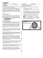
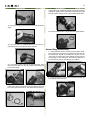
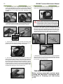
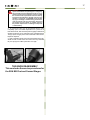
S.E.A.
(Survival Egress Air)
MK
TECHNICAL MANUAL
REV 01/10
2
SEA MK Technical Maintenance Manual
Copyright Notice
This manual is copyrighted, all rights reserved. It may not, in whole or in part, be copied, photocopied,
reproduced, translated or reduced to any electronic medium or machine-readable format without prior
consent in writing from Aqua Lung America International, Inc.
©2010 Aqua Lung America
S.E.A. / MK TECHNICAL Manual, P/N 108348
You can contact a Technical Adviser via e-mail at:
[email protected]
[email protected]
[email protected]
[email protected]
[email protected]
[email protected]
Trademark Notice
Aqua Lung , is a registered trademark of Aqua Lung America, Inc.
®
Warnings, Cautions, & Notes
Pay special attention to information provided in warnings, cautions and notes that are accompanied
by one of these symbols:
A WARNING indicates a procedure or situation that,
if not avoided, could result in serious injury or death
to the user.
A caution indicates any situation or technique that
could cause damage to the product, and could
subsequently result in injury to the user.
A Note is used to emphasize important points, tips
and reminders.
3
CONTENTS
Change Record.....................................................................................................................................4
Copyright Notice....................................................................................................................................5
General Guidelines................................................................................................................................5
General Conventions.............................................................................................................................5
Initial Inspection Procedure...................................................................................................................6
External Inspection...........................................................................................................................6
Immersion/Leak Test .......................................................................................................................6
Medium Pressure (Over-Bottom) Test . ............................................................................................6
DISASSEMBLY PROCEDURE..............................................................................................................7
First Stage Disassembly...................................................................................................................7
Second Stage Disassembly..............................................................................................................9
REASSEMBLY PROCEDURE............................................................................................................. 11
First Stage Reassembly.................................................................................................................. 11
First Stage Testing..........................................................................................................................14
Second Stage Reassembly............................................................................................................14
Adjusting the Second Stage...........................................................................................................15
FINAL TESTING..................................................................................................................................16
Subjective Test ..............................................................................................................................16
Immersion Test ..............................................................................................................................16
Table 1: Troubleshooting Guide for First Stage/Valve Assembly..........................................................18
Table 2: Troubleshooting Guide for Second Stage..............................................................................18
Table 3: List of Tools and Service Kits.................................................................................................20
Table 4: Torque Specifications.............................................................................................................24
Table 5: Test Bench Specifications .....................................................................................................24
Table 6: Recommended Cleaners and Lubricants...............................................................................24
Procedure A: Cleaning and Lubricating...............................................................................................25
S.E.A. First Stage with Cylinder Assembly, Exploded View................................................................26
MK Second Stage, Exploded View......................................................................................................27
Maintenance Notes..............................................................................................................................28
4
SEA MK Technical Maintenance Manual
CHANGE RECORD
Change No.
Date
Title or Description
Change made by
001-11
10/6/11
P. 20-23 Table 3: List of Tools and Service
Kits Updated
AQA
5
Introduction
This manual provides factory prescribed procedures for the correct
service and repair of the Aqua Lung SEA MK. It is not intended to be used
as an instructional manual for untrained personnel.
The procedures outlined within this manual are to be performed only by
personnel who have received Factory Authorized training through an
Aqua Lung Service & Repair Seminar. If you do not completely understand all of the procedures outlined in this manual, contact Aqua Lung to
speak directly with a Technical Advisor before proceeding any further. MK
has black external parts, however, chrome parts are used in this manual
for clarification.
Scheduled Service
The SEA MK should be given the same care and maintenance
as life support equipment. It is therefore important to perform
scheduled overhaul service for the complete unit, according to
the procedures outlined in this manual on a regularly scheduled
basis; once every two years with normal use.
General Guidelines
1. In order to correctly perform the procedures outlined in this
manual, it is important to follow each step exactly in the order
given. Read over the entire manual to become familiar with all
procedures before attempting to disassemble the product in
this manual, and to learn which specialty tools and replacement
parts will be required. Keep the manual open beside you for
reference while performing each procedure. Do not rely on
memory.
2. All service and repair should be carried out in a work area
specifically set up and equipped for the task. Adequate lighting,
cleanliness, and easy access to all required tools are essential
for an efficient repair facility.
3. Before beginning any disassembly, it is important to first
perform the Initial Inspection procedure. Refer to Tables 1 & 2:
Troubleshooting, p. 18 & 19, to determine the possible cause
of any symptoms which may be present.
4. As each unit is disassembled, reusable components should
be segregated and not allowed to intermix with nonreusable
parts or parts from other units. Delicate parts, including inlet
fittings and crowns which contain critical sealing surfaces, must
be protected and isolated from other parts to prevent damage
during the cleaning procedure.
5. Use only genuine Aqua Lung ® parts provided in the overhaul
parts kit for this product. DO NOT attempt to substitute an Aqua
Lung ® part with another manufacturer’s, regardless of any
similarity in shape or size.
6. Do not attempt to reuse mandatory replacement parts under
any circumstances, regardless of the amount of use the product
has received since it was manufactured or last serviced.
7. When reassembling, it is important to follow every torque
specification prescribed in this manual, using a calibrated torque
wrench. Most parts are made of either marine brass or plastic,
and can be permanently damaged by excessive stress.
General Conventions
Unless otherwise instructed, the following terminology and techniques
are assumed:
1. When instructed to remove, unscrew, or loosen a threaded
part, turn the part counterclockwise.
2. When instructed to install, screw in, or tighten a threaded part,
turn the part clockwise.
3. When instructed to remove an o-ring, use the pinch method
(see illustration below) if possible, or use a brass or plastic o-ring
removal tool. Avoid using hardened steel picks (unless directed),
as they may damage the o-ring sealing surface. All o-rings that are
removed are discarded and replaced with brand new o-rings.
4. The following acronyms are used throughout the manual: LP
is Low Pressure; MP is Medium Pressure; and HP is High
Pressure.
5. Numbers in parentheses reference the key numbers on the
exploded parts schematics on pages 26 and 27. For example, in
the statement, “...remove the o-ring (31) from the...”, number 31 is
the key number to the piston head o-ring.
Pinch Method
Press upwards on sides of o-ring to
create a protrusion. Grab o-ring or
insert o-ring tool at protrusion.
6
SEA MK Technical Maintenance Manual
Initial Inspection Procedure
Medium (Over-Bottom) Pressure Test
External Inspection
1. When possible, inspect the filter of the fill adapter for any signs that contaminants, such as moisture or
particulate matter, may have entered the system.
2. Visually inspect the MP hose along its length for any signs of deterioration or damage, such as blistering,
abrasion, or corrosion of the fittings.
3. Slowly pressurize the system by turning the on-off
handwheel counterclockwise
4. Examine the pressure indicator (pin or dial) to deter- mine whether the pin is within the full range or dial is
in the green, indicating that the SEA MK cylinder is full.
NOTE: If the pin indicator or dial indicator does not indicate
that the cylinder is completely full, it will be necessary to
perform the filling procedure outlined in the SEA MK Owner’s
Manual before proceeding further.
WARNING: Only use the SEA MK with normal, atmospheric,
compressed air (21% oxygen and 79% nitrogen by volume).
DO NOT attempt to fill with pure oxygen, or enriched air
which contains more than 23.5% oxygen. Failure to observe
this warning may result in serious injury or death due to fire
and explosion, or the serious deterioration and failure of the
equipment.
Immersion / Leak Test
1. After ensuring that the system is pressurized and the cyl- inder is full, listen for any obvious signs of leakage from the system, including free flow from the second stage.
CAUTION: If a second stage leak is detected, carefully
perform the medium pressure test. Use caution and avoid
over pressurizing the MP test gauge. Performing this test
may cause damage to the test gauge, and possibly result
in serious personal injury.
2. If there are no detectable leaks, immerse the entire sys- tem in fresh water. Check for any bubble streams to
locate the source of any leakage.
3. Note the source of any leakage found and refer to Table 2: Troubleshooting, p. 18 & 19 to determine its possible cause.
4. Close the valve and depress the second stage purge to completely depressurize the system. Wait at least five minutes, and depress the second stage purge to determine whether any air pressure has built up inside the
MP hose and second stage valve.
NOTE: A buildup of pressure is caused by either a bad
valve seat (20) or damaged sealing surface inside the
body (36). If a buildup of air pressure occurs, check both
items. Replace the valve seat first. If the problem still
occurs, replace the body.
1. With the valve closed, purge the second stage to depres-
surize the system. While securely holding the second stage inlet fitting (51) with a thin 3/4" open-end wrench, apply an 11/16" open-end wrench to the female fitting of the MP hose. Turn the hose fitting counterclockwise to loosen and remove the hose from the second stage.
2. Connect the medium pressure test gauge (PN 111610) to the female fitting of the MP hose, and tighten
the hose fitting by hand until finger tight.
3. While holding the MP test gauge positioned so that it is facing away from you, pressurize the system by slowly turning the SEA MK valve handle counterclockwise.
Check the SEA MK pin indicator or dial gauge to ensure that it indicates the cylinder is filled with at least 2,700 psi. 4. Note the medium (over-bottom) pressure indicated by the test gauge, and briefly open and shut the bleed
valve of the test gauge to ensure that lockup is achieved without “creeping” or fluctuating back and forth.
5. If the medium pressure “creeps” up or otherwise
fluctuates after cycling the regulator, wait for it to stabilize
(if possible) before noting the final medium pressure.
NOTE: Correct medium pressure for the SEA MK is 135
(±20) psi, with an inlet pressure between 2,500 - 3,000 psi.
6. Partially open the bleed valve of the MP test gauge to empty the SEA MK cylinder very slowly. DO NOT fully
open the test gauge bleed valve to empty the cylinder, as this may cause condensation of moisture to form inside the first stage and hose, as well as the cylinder itself. If the cylinder or valve becomes cold to the touch while
performing this step, the air has been relieved too rapidly. WARNING: Failure to completely empty the SEA MK of air
prior to performing any disassembly may cause the sudden
separation of components or ejection of parts, and may
result in serious personal injury.
7
DISASSEMBLY PROCEDURE
NOTE: Before performing any disassembly, refer
5. Unscrew and discard the burst plug (6) from the first stage
(36) using a 3/8" socket.
to the exploded parts drawing, which references all
mandatory replacement parts. These parts should
be replaced with new and must not be reused
under any circumstances – regardless of the age of
the regulator or how much use it has received since
it was last serviced.
CAUTION: Use only a plastic or brass o-ring removal
tool (pn 944022) when removing o-rings to prevent
damage to the sealing surface. Even a small scratch
across an o-ring sealing sur face could result in
leakage. Once an o-ring sealing surface has been
damaged, the part must be replaced with new. DO
NOT use a dental pick or any other steel instrument.
6. Unscrew the valve handwheel retaining nut (7) using a
medium flat blade modified screwdriver (pn 9-47448). Remove
the washer (8), spring (9), handwheel (10), washer (11) and
indicator ring (12) from the stem (19).
First Stage Disassembly
1. Completely open the on-off handwheel (10). Make sure
all the air is completely drained from the cylinder (see p.6,
step 6).
12
11
10
9
8
7
7. Using a 3/4" wrench, unscrew the bonnet (13) from the first
stage body. Pull the valve stem (19) out of the bonnet.
2. While holding the second stage inlet fitting (52) with a thin
3/4" wrench (not wider than the nut), use an 11/16" wrench to
unscrew the hose from the second stage.
hold
3. Remove and discard the o-ring (16) located inside the hoseend swivel fitting, using o-ring removal tool (pn 10-102-400). DO
NOT use this tool on any other parts or damage may result.
8. Remove the backup ring (15), o-ring (16), spacer (17) and
washer (18) from the stem. (Note: It is possible that some or
all of these parts are in the bonnet.) Discard backup ring, oring and washer.
18
check bonnet
4. Using a 3/16" hex key, unscrew the swivel port plug (1) from
the first stage body. Separate the hose (4) and spacer (5) from the
fitting. Remove the o-rings (2 & 3) from the swivel port plug.
17
16
15
9. Remove the o-ring (14) from the bonnet.
8
SEA MK Technical Maintenance Manual
10. Insert the squared end of the stem into the valve seat
(20) and unscrew and discard the valve seat from the first
stage body.
b
. Using a 1/8" hex key unscrew the retaining screw (27g)
from the pin indicator body (27b). Remove the spring (27e)
and pin (27f).
27b
27e
27b
27g
11. Using a magnifier, inspect the condition of the crown.
There should be no scratches, nicks or dents on the crown
sealing surface.
27g
c . Turn the indicator body upside down to remove the washer (27d) and o-ring (27c). If they do not exit the body
freely, use an o-ring removal tool to extract these parts.
27c
12. If the SEA MK is equipped with a dial-type pressure indicator (27), remove the gauge using a 7/8" wrench.
13. If equipped with a pin-type pressure indicator (27a), remove
the gauge with valve handling retainer tool (pn 053035). For
either gauge, remove and discard the o-ring (22).
27f
27d
15. Using your fingers, unscrew the fill port plug (21) from the
end of the fill adapter port (23). Remove the o-ring (22) from
the fill port plug.
NOTE: There is a small pin inside the adapter port.
Take care not to lose the pin when the adapter port
is removed.
16. Using a 9/16" wrench, unscrew the fill adapter port (23)
from the first stage body. Remove and discard the o-ring
(22). Remove the check valve (26) and the o-ring (25) from
the check valve.
14. Disassembly of pin-type pressure indicator
CAUTION: The pin indicator parts are under spring
pressure. Be sure to apply pressure against the
retaining screw (27g) while unscrewing it from the
indicator body (27b).
a. If the o-ring (22) has not been removed yet, do so now.
NOTE: The check valve may be in either the first
stage or the fill port plug.
9
17. Remove and discard the fill adapter port o-ring (22).
22. Using the bottle vice (pn 100397), vice insert (pn 100398)
or strap wrench (pn 54325A22), hold the cylinder secure. While
holding the cylinder secure, unscrew the first stage body (36)
from the cylinder using a 1 3/16" crowfoot & flex handle drive.
18. Using your fingers, peel the cap protector (29) off the first
stage.
23. Remove and discard the o-ring (37) from the cylinder threads.
19. Insert the pins of an adjustable spanner wrench into corresponding holes in the top of the piston cap (30).
Second Stage Disassembly
1. Using small wire cutters, carefully snip the plastic mouthpiece clamp (55) and remove the mouthpiece (58) from the
box bottom (54). Inspect the mouthpiece to ensure it is free
of any tears or cuts that may cause leakage of water into the
second stage or other discomfort. Discard the mouthpiece or
set it aside to be reused, depending on its condition.
20. Unscrew the piston cap from the first stage body. Separate the piston (32) from the cap. Remove the spring (35)
from the first stage.
2. Using your fingers, unscrew the front cover assembly (40
& 41) from the box bottom (54).
21. Remove and discard the o-rings (31 & 33) from the piston.
Insert the pin of the seat extraction tool (pn 109437) down the
bore of the piston and press out and discard the HP seat (34).
31
33
34
10
SEA MK Technical Maintenance Manual
3. Lift out the Ring Cover Support (42) and diaphragm (43).
Inspect the diaphragm for any tears or pin holes by holding it
up to a light and gently stretching around the perimeter. Discard
the diaphragm or set it aside to be reused, depending on its
condition.
4. While depressing the lever (45), unscrew the inlet fitting (52) using
a 3/4" wrench. Remove and discard the inlet fitting o-ring (14).
7. Remove and discard the exhaust valve (56) by grasping the
flap of each valve and pulling straight outward.
CAUTION: Valve assembly parts are under spring
pressure. When removing the locknut (44), be sure to
keep the poppet side of the valve assembly against
the work surface or place a finger over the poppet to
prevent the parts from ejecting from the valve body.
8. Hold the valve assembly, poppet side facing down, firmly
against the work surface. Using a 1/4" nutdriver, remove and
discard the locknut (44). Separate the locknut (44), washer (46),
lever (45), poppet (50), and spring (49) from the valve body (47).
Using the threaded end of the poppet, press the poppet bearing
(48) out of the valve body from the outside to the inside.
inlet fitting
50
49
47
45
5. Gently grasp the lever and remove the entire valve
assembly (44-51) from the box bottom. It may be necessary to
push in on the valve assembly through the inlet hole.
6. The exhaust cover (57) is held in place by four tabs: One
side has two short tabs (usually on top), and the other side has
two longer tabs (usually on bottom). The two longer tabs come
all the way through until flush with the box bottom; the shorter
tabs are recessed. The exhaust cover is removed by popping
out the short tabs. To do this, use your index and middle fingers
to press downward on the center rib, toward the long tabs, while
simultaneously pulling out on the exhaust cover.
46
44
9. Using the tip of the o-ring removal tool, or any type of pointed
tip type tool, pierce the center of the low pressure seat (51) and
remove it from the poppet. DO NOT discard the seat, as it will
be used later to aid in reassembly.
THIS ENDS DISASSEMBLY
Before starting reassembly, perform parts
cleaning and lubrication in accordance with
Procedure A: Cleaning and Lubricating
(p. 25).
11
REASSEMBLY PROCEDURE
4. Place the spring (35) into the body. Press the piston into
the cap (30) so that the piston head is seated flat against the
cap. Verify there is no dirt or damage to the smooth inner sides
of the cap.
First Stage Reassembly
CAUTION: Before proceeding, visually inspect the
cylinder according to Compressed Gas Association
(CGA) standards (pamphlet CGA C-6.1--1984, "STANDARDS FOR VISUAL INSPECTION OF HIGH PRESSURE ALUMINUM COMPRESSED GAS CYLINDERS".
This inspection requires a visual inspection light.
If the cylinder does not pass the visual inspection,
it must be serviced or replaced with a new cylinder
before it can be assembled and filled.
*Lubricate all O-rings with Christo-Lube ® before assembly.
1. Install a new, lightly lubricated o-ring (37) over the cylinder
threads so that it is seated against the first stage body. Lubricate
the first 4 to 5 threads on the first stage body with ChristoLube®. Do not use an excessive amount.
35
30
5. Lightly lubricate the first stage body threads. Pass the piston shaft through the spring. While pressing down on the cap,
handtighten the cap onto the first stage by turning clockwise.
Tighten the cap with an adjustable spanner wrench until the
cap stops against the first stage body.
37
29
2. Place the cylinder in the Bottle Vice or Vice Insert. Attach
a 1 3/16" crow foot adapter to a torque wrench. Tighten the
regulator body to 25 ± 2 ft/lbs OR:
2a. Thread the first stage into the cylinder until handtight. Attach a 1 3/16" crowfoot adapter to a torque wrench. Apply a
strap wrench to the cylinder. While holding the cylinder firmly,
tighten the first stage body to a torque value of 25 ± 2 ft/lbs.
3. Install a new lubricated piston shaft o-ring (33) and piston
head lubricated o-ring (31) onto the piston (32). Closely inspect
the edges of new HP seat (34). One edge is sharp and one edge
has a chamfer. With the chamfered edge facing outward, press
the HP seat into the small, recessed hole in the end of the piston. The easiest method is to place the chamfered edge down
on a flat surface and simply press the piston down over it.
33
32
34
6. Install a new lubricated o-ring (25) onto the shaft of the
check valve (26). Install a new lubricated o-ring (22) onto the
fill port plug (21).
7. Insert the check valve (26), o-ring side first, into the malethreaded end of the fill adapter port (23). Install a new lubricated
o-ring (22) onto the fill adapter port. Lubricate the threads,
then thread the fill adapter port into the lower of the two high
pressure ports.
23
26
8. Attach a 9/16" socket adapter to a torque wrench and tighten
the fill adapter port (23) to 90±3 in/lbs. Do not overtighten damage to the fill port adapter will result.
12
SEA MK Technical Maintenance Manual
9. SEA MK with a pin-type pressure indicator (27a):
a.
Drop a new lubricated o-ring (27c) into the pin indicator
body (27b), making sure it is properly seated in the small
recess inside the body. Drop the washer (27d) over the oring, making sure it is laying flat atop the o-ring.
b
. Insert the spring (27e) into the indicator body and insert
the pin (27f) into the spring. Place the retaining screw
(27g) on the pin and press the retaining screw against
the indicator body. While keeping the retaining screw
pressed against the indicator body, turn the indicator
body counterclockwise to engage the screw threads.
27f
27e
27b
10. SEA MK with a dial-type pressure indicator (27):
a. Install a new o-ring (22) onto the dial pressure indicator
(27). Thread the pressure indicator into the upper HP port and
torque to 45±3 in/lbs using a 7/8" crowfoot wrench.
11. Thread a new burst plug (6) into the lower port on the first stage
body (the side opposite of the fill adapter). Attach a 3/8" socket to
a torque wrench and tighten the burst plug to 90±3 in/lbs.
Press retaining screw
against body and hold
27g
Turn body to
engage threads
12. Install new lubricated o-rings (2) into the grooves located on
either side of the center hole of the swivel port plug (1). Install a
new o-ring (3) on the threaded end of the swivel port plug.
c . Using a 1/8" hex key, tighten the retaining screw by
turning it clockwise until it stops. Install a new o-ring
(22) onto the threaded end of the indicator body. Thread
the pressure indicator into the upper HP port until firmly
fingertight. Use the T-handle tool (pn 053035) to tighten.
Maintain firm pressure to avoid damage to the pin gauge.
22
13. Pass the threaded end of the swivel port plug through the
hose swivel, then through the spacer (5). Make sure that both
o-rings (2) are covered by the hose swivel. Thread the swivel
adapter into the first-stage body. Attach a 3/16" hex key to a
torque wrench and tighten the swivel port plug to 60±3 in/lbs.
5
2
13
14. Place a new, lubricated white washer (18) onto the valve
stem (19), followed by the metal spacer (17) and lubricated
o-ring (16).
NOTE: Before continuing, closely examine the
back up ring (15). You will note that it has a flat
side and a concave side. For correct assembly
the concave side should be against the o-ring
(16), as shown in the picture below.
17. Attach a 3/4" crowfoot or medium deep-well socket to a
torque wrench and tighten the bonnet to 90±3 in/lbs.
CAUTION: DO NOT over-torque. Damage to the bonnet
will occur.
18. Place the washer (11) over the stem, against the bonnet.
With the rounded edge of the indicator ring (12) facing outward,
lightly thread the indicator ring onto the bonnet. When the
indicator ring bottoms out, turn it slightly counterclockwise so
the corners of the square shaft of the stem point towards the
centers of the square cut outs of the indicator ring. Turn the
indicator ring an additional 90º, aligning the corners of the stem
to the next square cut outs.
Backup ring
O-ring
15. Lubricate the threads of the new high pressure seat. Then,
using the squared end of the stem (19), screw a new high pressure seat (20) into the first stage body until fingertight. Leave
the stem in the high pressure seat. Place the handwheel over
the stem and tighten the valve seat. Remove the handwheel.
CAUTION: Failure to fully seat the HP seat will damage the bonnet.
19. Place the handwheel (10) over the indicator ring. Place
the spring (9) into the valve handle, followed by the washer (8).
CAUTION: Start the retaining nut by hand. If any resistance is
felt, stop and remove, then start again to avoid cross threading.
Using the medium flat bladed screwdriver (pn 9-47488), screw
the retaining nut (7) onto the end of the stem until the retaining
nut will not turn any further.
16. Install a new lubricated o-ring (14) onto the bonnet (13)
so that the o-ring fits into the groove located above the longer
threads. Pass the bonnet over the stem and thread it into the
body.
9
14
SEA MK Technical Maintenance Manual
Second Stage Reassembly
8
7
1. Install a new exhaust valves (56) by inserting the stem of
the exhaust valve through the center hole of the exhaust port.
Pull the stem all the way through until the mushroom plug pops
through the hole and keeps the valve securely in place. Examine the flap of each exhaust valve to make sure it is laying flat
and is not distorted or folded under. Using a pair of small wire
cutters (pn 9-45171), snip the stem of the exhaust valve so it
is only about a 1/4" long.
20. Install a new lubricated o-ring (16) into the swivel end
(second stage end) of the hose. NOTE: This o-ring is in the
second stage rebuild kit (pn 108344).
2. Insert the two long tabs on the exhaust cover (57) into the
corresponding bottom two slots on the box bottom (54). Using
your index and middle fingers, press down on the center rib
and simultaneously press in on the two short tabs until they
pop into place.
First Stage Testing
NOTE: Initial first stage testing is done WITHOUT
anything attached to the end of the hose. For proper
filling instructions, refer to the operator's manual of
the fill equipment, e.g., MRSIII portable refill station,
cylinder fill adapter to fill from a larger cylinder, or
yoke fill adapter to fill from a compressor.
1. Cycle the handwheel on and off several times to ensure
the proper function of the indicator ring and valve seat. Close
the on-off valve by turning the handwheel (10) clockwise until
it stops.
long tabs
3. Press a new low pressure seat (51) into the end of the poppet (50) until it is flush and seated evenly. Ensure the dimpled
side is toward the poppet.
2. Remove the fill port plug (21) and attach the fill adapter.
Attach a 3000 psi supply to the fill adapter. Secure the end of
the hose prior to pressurizing.
3. Slowly begin to fill the cylinder with 3000 psi of air.
During the fill process, check any air leaking from the open
end of the hose. If an air leak is detected, immediately stop the
filling process consult the Table 1: Troubleshooting Guide
p. 18. If a leak is not detected, finish filling the cylinder to 3000
psig. Turn off the supply line valve and bleed the line pressure.
Remove the supply line from the fill adapter and unscrew the
fill adapter from the fill port. Reinstall the fill port plug.
4. Thread a medium pressure (MP) gauge to the hose until
fingertight. Slowly turn the handwheel (10) and open the valve.
Check the MP to make sure it "locks up" at 135±20 psig. Closely
monitor the MP gauge for a few minutes to make sure the MP
does not begin to creep upward. Any MP creep indicates a
small high pressure leak somewhere in the system. Cycle the
bleed valve open and closed on the IP gauge a minimum of
two times to insure the HP seat is seated and the regulator
stays locked up. If a MP creep is detected, consult Table 1:
Troubleshooting Guide p. 18.
5. Assuming the medium pressure is properly set, close the
SEA valve and open the bleeder valve on the MP gauge to
relieve the air from the system. Remove the MP gauge from
the end of the hose.
6. Since there is nothing attached to the end of the hose and
the cylinder is fully charged, set the system in a secure place
so that the valve cannot be accidentally opened.
51
50
4. Place the poppet bearing (48), rounded side first, onto the
stem of the poppet (50). Using the poppet as an installation
tool, insert the bearing into the barrel of the valve body (47).
Align the squared side of the poppet bearing with the square
hole in the valve body and press it into place. Remove the poppet. If the poppet bearing does not stay in place, put a small
amount of Christo-lube ® on the square sides of the bearing
and re-insert.
48
47
15
5. Install a new inlet fitting o-ring (14) in the groove located
between the wrench flats and shorter threads.
9. Place the washer (46) over the threads of the stem. Thread
a new locknut (44) onto the stem. Using a 1/4" nutdriver, tighten
the locknut until about two threads show past the locknut.
two threads
46
44
6. Take the used low pressure (LP) seat that was removed
during disassembly and place it on top of the crown sealing
surface inside the inlet fitting (52). Place the spring (49) over
the stem of the poppet (50) and set this assembly into the inlet
fitting, on top of the used LP seat.
10. Unscrew the inlet fitting from the valve body. Discard the
used LP seat. While depressing the lever with your finger,
thread the inlet fitting (52) back into the valve body.
50
52 51
49
NOTE: The used LP seat is only used to aid in reassembly. It will be removed and discarded later in the
reassembly procedure.
7. Place the barrel of the valve body (47) over the top of the
poppet. While pressing down on the valve body to compress
the spring, screw the valve body onto the inlet fitting. This will
fully expose the threads of the poppet.
Adjusting the Second Stage
11. Attach the valve assembly to the end of the hose until
fingertight. Slowly turn the SEA on/off valve (10) counterclockwise to open the valve. If a leak is detected while opening the
valve, immediately close the valve. Loosen the locknut a 1/2
turn and slowly open the valve again. Repeat this step until
the unit does not leak.
If air leaks when pressurized,
loosen locknut until leak stops
8. Place the "feet" of the lever (45) into the groove on the face
of the valve body (47) such that the lever is pointing away from
the air outlet hole.
45
feet
air
outlet
hole
12. Using a 1/4" nutdriver, tighten the locknut until air starts
to leak. As soon as a leak is detected, loosen the locknut until
the leak stops, then continue to loosen for another 1/4 to 1/2
turn.
Tighten until air leaks.
Loosen until air
leaks stops, then
loosen 1/4 to 1/2 turn
more.
16
SEA MK Technical Maintenance Manual
13. Close the SEA on/off valve by turning the handwheel
clockwise. Purge the air from the system by pressing down
on the lever. Remove the valve/inlet assembly from the hose.
While depressing the lever with your finger, unscrew the inlet
fitting from the valve body.
Press lever to
relieve pressure.
18. Install the mouthpiece (58) onto the box bottom. Loosely
fasten a tie-strap clamp (55) over the slots at the base of the
mouthpiece. Orient the clamp buckle to the side of the mouthpiece with the hose. Pull the clamp tight and snip the excess
strap flush with the buckle using a small pair of wire cutters.
Red indicates "off".
14. With the lever facing upward, reinsert the valve body back
into the box bottom. Make sure the flat sides of the valve body
(47) are within the plastic slot. This will prevent the valve body
from rotating when installing the inlet fitting.
15. While depressing the lever, thread the inlet fitting into the
valve body. It may be necessary to press inward on the valve
body to prevent it from rotating. Attach a 3/4" crowfoot to a
torque wrench and tighten the inlet fitting to 50±3 in/lbs.
19. Thread the hose onto the inlet fitting. Attach an 11/16"
crowfoot to a torque wrench. While holding the inlet fitting with
a 3/4" thin wrench, tighten the hose to 45±3 in/lbs.
FINAL TESTING
Subjective Test
1. Slowly open the SEA MK First Stage valve to pressurize
the system.
2. Press the purge cover a few times to ensure there is a
strong purge.
3. Perform a subjective breathing test to ensure that the second
stage is operating properly.
NOTE: Regulator must be cleaned and sanitized
per local instruction before issue.
16. Place the diaphragm (43) over the lever, making sure the
perimeter of the diaphragm is seated below the threads and
against the box bottom (54). Place the wider side of the Ring,
Cover Support (42) on top of the diaphragm.
17. Screw the front cover assembly (40 & 41) onto the box
bottom until fingertight.
Immersion Test
1. Refill the SEA to 3000 psi. Turn the SEA MK valve to the
"ON" position to repressurize, and check the pressure gauge
to ensure that the SEA cylinder is completely filled to 3,000 psi.
If the SEA has a pin gauge, ensure that the gauge indicates
correct pressure.
2. Remove the fill cap and protective rubber cover. Submerge
the entire system in a test tank of clean water with the valve
turned all the way open. Observe any bubbles arising from
the submerged system over a one minute period. The recommended time is necessary due to slower bubble formation
that occurs in smaller leaks. Bubbles indicate a leak, which
requires that the system must be disassembled at the source
to check sealing surfaces, assembly sequence and component
positioning in order to correct the problem(s).
NOTE: Do not confuse bubbles from trapped air
with a true leak. If there is an air leak, bubbles will
come out in a constant stream.
17
WARNING: The SEA MK is designed to assist helicopter crew members and passengers in emergency
egress situations from submerged aircraft. It is very
critical to ensure that no leakage is present, and that
the unit has met all requirements in the Final Testing
Procedures outlined above. DO NOT issue to a crew
member or passenger any SEA MK which exhibits
any signs of leakage or unsatisfactory performance
until the problem has been thoroughly diagnosed
and repairs have been made as needed, including
the possible replacement of a damaged component
or subassembly.
3. As a final test, leave the unit pressurized with the valve
completely open at a stable temperature for a period of at
least twelve hours, and check the pressure gauge to determine
whether any air loss occurs. If air loss occurs, repeat Immersion
Test (p. 16) for a longer period of time until leak is discovered.
Repair as required.
4. Upon completion of test, ensure no water remains in the cap.
Shake or blow out with clean air. Ensure unit is dry. Reinstall
fill port cap (21) and rubber protective cover (29).
21
23
This Ends Reassembly
This concludes the service procedures for
the SEA MK First and Second Stages.
18
SEA MK Technical Maintenance Manual
Table 1: Troubleshooting Guide
First Stage/Valve Assembly
Symptom
Possible Cause
Treatment
LP system will not remain depressurized 1. The valve seat (20) is worn or damaged.
after valve is shut and second stage is
purged.
2. The valve seating surface is damaged.
1. Replace valve seat.
1.The valve seat (20) is worn or damaged.
1. Replace valve seat .
2. The valve seating surface is damaged.
2. Replace body (36).
3. The main spring (35) is defective.
3. Replace main spring.
4. The HP seat (34) is worn or damaged.
4. Replace HP seat.
5. The HP crown sealing surface is
damaged.
5. Replace o-ring.
1. Main spring (35) is weakened or
damaged.
1. Replace spring (35).
1. The piston head o-ring (31) or shaft o-ring
(33) is worn or damaged.
1. Replace o-ring(s).
2. The o-ring grooves on the piston (32)
are damaged.
2. Replace piston.
3. The piston head o-ring sealing surface in
the piston cap (30) is damaged.
3. Replace piston cap.
High or Unstable MP
Low MP
External Air Leak
4. The piston shaft o-ring sealing surface in
the body is damaged.
2. Replace body (36).
4. Replace body.
5. Retorque or replace.
5. Blow out plug not seated correctly.
6. C
heck seating surface for nicks or
debris.
Table 2: Troubleshooting Guide
Second Stage
Symptom
Leakage or freeflow from the
second stage
Possible Cause
Treatment
1. High first stage MP (should be 135±20
psi).
1. Refer to first stage Troubleshooting
Guide above.
2. The LP seat (51) is worn or damaged.
2. Replace LP seat.
3. The lever (45) is set too high.
3. Readjust locknut.
4. The lever (45) is damaged.
4. Disassemble second stage
and replace lever.
5. The crown sealing surface on the inlet
fitting (52) is worn or damaged.
5. Replace inlet fitting.
6. The poppet (50) is worn or damaged.
6. Replace poppet and LP seat.
7. The poppet spring (49) is damaged.
7. Replace poppet spring.
19
Table 2: Troubleshooting Guide
Second Stage (continued)
Symptom
Low purge or breathing effort is too
high (full cylinder)
External Air Leak
(Immersion Test)
Water entering second stage
Possible Cause
Treatment
1.Low MP (should be 135±20 psi).
1. Refer to Table 1: Troubleshooting
Guide First Stage, p. 18.
2. The lever (45) is set too low.
2. Readjust locknut.
3. The lever (45) is bent.
3. Disassemble second stage and
replace lever.
4. The poppet spring (49) is incorrectly
installed.
4. Disassemble second stage and
reinstall poppet spring.
5. The MP hose is clogged or obstructed.
5. Clean or replace hose.
1.The MP hose is loose.
1. Tighten hose to 45 in/lbs at second
stage fitting.
2. The MP hose o-ring is damaged.
2. Disassemble and replace o-ring.
1. The mouthpiece (58) has a hole.
1. Replace mouthpiece.
2. The demand diaphragm (43) is damaged.
2. Replace demand diaphragm.
3. The exhaust valve (56) is damaged.
3. Replace exhaust valve.
4. The diaphragm is improperly seated
between the box bottom (54) and purge
cover ring (41).
4. Disassemble and properly
reassemble (check for distortion).
5. The box bottom (54) is damaged.
5. Check exhaust valve sealing
surface replace box bottom.
6. The valve body o-ring (53) is damaged.
6. Disassemble and replace o-ring.
NOTE: This is a partial list of possible problems and recommended treatments.
For more information, contact Aqua Lung Technical Service Department for assistance with problems not described here.
CAUTION: Recommended treatments which require disassembly of the regulator must
be performed during a complete overhaul, according to the prescribed procedures for
scheduled, annual service. Do not attempt to perform partial service.
20
SEA MK Technical Maintenance Manual
Table 3: List of Tools and Service Kits
PART #
DESCRIPTION
APPLICATION
108361
Tool Pouch
SEA MK / LV2
Tool holder
111610
Test Gauge
0-400 psi
Checking medium pressure
108362
Soft Case,
IP Test Gauge
IP test gauge
108325
SCUBA Fill
Adapter
IP testing and filling
944022
O-ring Tool
Kit
Removing and installation of o-rings
10-102-400 O-ring Tool
Internal hose o-ring (16)
100188
Micra Retaining
Ring Wrench
Retaining ring removal and installation
107394
Adjustable
Spanner
Wrench
Piston cap (30) removal and installation
109437
Seat
Extraction
Tool
HP seat (34) removal
108357
Repair Mat
with Windows
Service and maintenance
21
Table 3: List of Tools and Service Kits (continued)
PART #
DESCRIPTION
APPLICATION
820466
Christo-Lube MCG III
2 oz. tube
Lubrication
9-AM11708
9-46661
Hex Bit Tool (1/8”)
Hex Bit Tool (3/16”)
Pin-type pressure indicator (27a) and LP swivel port plug (1)
9-45171
Diagonal Pliers
(small)
Mouthpiece clamp (55)
9-47709
Cylinder
Light
Cylinder (38) visual inspection
9-BA819008
Magnifier
w/Illumination
Sealing surface spring inspection
9-43001
9-43004
9-43226
3/8” Socket
9/16” Socket
3/4” Socket
Burst plug (6) (3/8”), Fill adapter port (23) (9/16”), Bonnet (13)
and 2nd stage inlet fitting (52) (3/4”)
9-43625
9-43628
9-43626
11/16” Crowfoot
7/8” Crowfoot
3/4” Crowfoot
Hose fitting (11/16”), Dial pressure indicator (27) (7/8”),
Bonnet (13) (3/4”)
FC38A
1 3/16” Crowfoot
1st stage body (36)
9-44388
Wrench
(11/16”)
Hose fitting (11/16”)
Tappet
Wrench
(7/8” & 3/4”)
Inlet fitting (52)
Wrench
(7/8” & 3/4”)
Pressure indicator, bonnet (13)
LTA2428
9-44584
22
SEA MK Technical Maintenance Manual
Table 3: List of Tools and Service Kits (continued)
PART #
DESCRIPTION
APPLICATION
9-44572
9-44385
9-44592
3/8” & 7/16” Wrench
1/2” Wrench
5/8” & 9/16” Wrench
MRS III
9-44605
12’ Adjustable
Wrench
MRS III
947448
Medium Blade
Modified
Screwdriver
Handwheel retainer nut (7)
9-41971
1/4” Nut
Driver
Lock nut (44)
5682A28
#2 Phillips
Screwdriver
MRS III
111100
Circlip Pliers
MRS III
9-44363
3/8” Drive,
Flex Handle
Removal of parts
053035
Valve Handle
Retainer Tool
Pin Type Pressure Indicator (27a) / MRS III
54325A22
Strap
Wrench
Cylinder removal (52)
108342
Tool Kit (includes all items listed above
for SEA LV-2, SEA-MK and MRS III)
SEA LV-2 / SEA-MK / MRS III Maintenance
23
Table 3: List of Tools and Service Kits (continued)
PART #
DESCRIPTION
APPLICATION
820467
Christo-Lube MCG III
16 oz. tube
Lubrication
100398
HABD/SEA
Vise Jaw Inserts
SEA cylinder removal and installation for use w/ existing vice
HABD/SEA
Table Mount
Bottle Vise
SEA cylinder removal & installation
Torque
Wrench
ft/lbs / in/lbs
Apply torque to parts listed in
Table 4: Torque Specifications, p. 24
100397
N/A
NOTE: Photos of tools contained in the SEA tool kit are representative. Tool
manufacturers and part numbers are subject to change without notice.
24
SEA MK Technical Maintenance Manual
Table 4: Torque Specifications
PART #
DESCRIPTION / KEY ITEM #
TORQUE
108312
1st stage body (item 36/1st stage)
25±2 ft/lbs / 33.9±3 Nm
102812
Swivel port plug (item 1/1st stage)
60±3 in/lbs / 6.8±.3 Nm
054201
Burst plug (item 6/1st stage)
90±3 in/lbs / 10.2±.3 Nm
108318
Bonnet (item 13/1st stage)
90±3 in/lbs / 10.2±.3 Nm
108308
Fill adapter port (item 23/1st Stage)
90±3 in/lbs / 10.2±.3 Nm
742537
Pressure gauge blk (item 27/1st stage)
45±3 in/lbs / 5.0±.3 Nm
108346
Pin type pressure indicator (item 27a/
1st stage)
20±2 in/lbs / 2.3±.2 Nm
(or wrench tight)
1006-25
MP hose assembly (item 4/1st stage)
45±3 in/lbs / 5.0±.3 Nm
108338
Inlet fitting (item 52/2nd stage)
50±3 in/lbs / 5.6±.3 Nm
Table 5: Test Bench Specifications
TEST
CONDITION
SPECIFICATION
Leak Test
Inlet 2,500-3,000 (±100) psi
No leaks allowed
MP
Inlet 2,500-3,000 (±100) psi
135±20 psi
MP Creep
Inlet 2,500-3,000 (±100) psi
5 psi max between 5 to 15 seconds
after cycling regulator (purge)
Opening Effort
Inlet 2,500-3,000 (±100) psi
MP 135±20 psi
+1.4 to +3.0 inch H20
Flow Effort
MP 135±20 psi at 5 SCFM
+5 inches H20 (maximum)
Purge Flow
MP 135±20 psi
5.0 SCFM flow rate (minimum)
Table 6: Recommended Cleaners and Lubricants
LUBRICANT/CLEANER
Christo-Lube MCG 111
APPLICATION
SOURCE
All o-rings
Aqua Lung, PN 820466, or
Lubrication Technologies
310 Morton Street
Jackson, OH 45640
(800) 477-8704
CAUTION: Silicone rubber requires no lubrication or preservative treatment.
DO NOT apply grease or spray to silicone rubber parts. Doing so may cause a
chemical breakdown and premature deterioration of the material.
Oakite #31
Acid bath for reusable stainless steel and
brass parts.
Oakite Products, Inc.
50 Valley Road
Berkeley Heights, NJ 07922
CAUTION: Do not use muriatic acid for the cleaning of any parts. Even if
strongly diluted, muriatic acid can harm chrome plating and may leave a
residue that is harmful to o-ring seals and other parts.
White distilled vinegar
Acid bath for reusable stainless steel
and brass parts.
“Household” grade
Liquid dishwashing detergent
(diluted with warm water)
Degreaser for brass and stainless steel
parts; general cleaning solution for plastic
and rubber
“Household” grade
25
Procedure A: Cleaning and Lubricating
Cleaning Brass and Stainless Steel Parts
1. Preclean in warm, soapy water* using a nylon bristle tooth brush.
2. Thoroughly clean parts in an ultrasonic cleaner filled with soapy water. If there are stubborn deposits, household white distilled vinegar (acetic acid) in an ultrasonic cleaner will work well. DO NOT place plastic, rubber or silicone parts in vinegar.
3. Remove parts from the ultrasonic cleaner and rinse with fresh water. If tap water is extremely “hard,” place the parts in a bath of distilled water to prevent any mineral residue. Agitate lightly, and allow to soak for 5-10 minutes. Remove and blow dry
with low pressure (25 psi) filtered air, and inspect closely to ensure proper cleaning and like-new condition.
Cleaning Plastic & Rubber Parts
Parts made of plastic or rubber, such as box bottoms, box tops, dust caps, etc., may be soaked and cleaned in a solution of warm water
mixed with mild dish soap. Use only a soft nylon toothbrush to scrub away any deposits. Rinse in fresh water and thoroughly blow dry,
using low pressure filtered air.
CAUTION: Do not place plastic and rubber parts in acid solutions.
Doing so may alter the physical properties of the component, causing
it to prematurely degrade and/or break.
Cleaning Hoses
1. Hose fittings: Ultrasonically clean with soapy water*; vinegar OK on tough corrosion
2. Run soapy water through hose if needed
3. Thoroughly rinse with fresh water
4. Blow out hose before installing
Lubrication and Dressing
Wear powderless, latex gloves when handling and lubricating o-rings. Keeping internal parts free from skin oils and other contaminates
is important when running enriched air nitrox through a first stage. All o-rings should be lubricated with Christo-Lube® MCG-111. Dress
the o-rings with a very light film of grease, and remove any visible excess by running the o-ring between thumb and forefinger. Avoid
applying excessive amounts of Christo-Lube grease, as this will attract particulate matter that may cause damage to the o-ring.
*Soapy water is defined as “household” grade liquid dishwashing detergent diluted in warm water.
CAUTION: Silicone grease and sprays must be strictly avoided for the
SEA MK, since silicone does not provide adequate lubricity in extreme
weather conditions.
26
SEA MK Technical Maintenance Manual
S.E.A. First Stage with Cylinder Assembly
29
30
38a, 38b, 38c
31
32
4
27g
27b
25
27d
27f
27e
33
34
35
Wrench
Tight
27a
22
NLA - No Longer Available
27
18
16
23
25 26
90 ± 3 in. lbs.
(10.2 ± .3 Nm)
Key # Part # Description
........108343Overhaul Service Kit
........108311
First Stage, Spare
........108469 First Stage, Spare, USCG/CBP
1........108305 Port Plug, Swivel, Black
........108333 Port Plug, Swivel, Chrome
2........820312PO-ring (10 pk)
3........820311PO-ring (10 pk)
4........100625 Hose Assy. MK, 27" Black
........102835 Hose Assy. MK, 20" Black
........108392 Hose Assy. LV2, 27” Black
........108391 Hose Assy. LV2, 20” Black
5........108306 Spacer, Black
........108334 Spacer, Chrome
6........054201 Burst plug
7........108304 Retaining Nut, Handwheel, Black
........108314 Retaining Nut, Handwheel, Silver (NLA)
8........108329 Washer, Handwheel
9........108316 Spring, Handwheel
10........108313 Handwheel
11........108326 Washer
12........108317 On-off indicator ring
13........108318 Bonnet
14........820015O-ring (10 pk)
15........828009 Backup ring
16........820010O-ring (25 pk)
17........108328 Spacer, metal
18........108327 Washer, white Teflon®
19........108319 Stem
20........108322 Valve seat
21........108307 Fill port plug
22........820319O-ring (10 pk)
1
90 ± 3 in. lbs.
(10.2 ± .3 Nm)
6
20
22
2
60 ± 5 in. lbs.
(6.8 ± .5 Nm)
22
45 ± 2 in. lbs.
(5.0 ± .5 Nm)
21
3
5
37
36
14
90 ± 3 in. lbs.
(10.2 ± .3 Nm)
13
19
17
25 ± 2 ft. lbs.
(33.9 ±2.7 Nm)
15
On-off valve assembly may be
replaced with optional "no onoff" plug, part number 108367
(see key # 39 below) & part
number 820015 (see key # 14
below).
On/Off Valve
Conversion Kit
PN 108441
12
10
9
14
8
11
39
90 ± 3 in. lbs.
(10.2 ± .3 Nm)
Key # Part # Description
23........108308 Fill adapter port
25........820304O-ring (10pk)
26........108309 Check valve
27........742537 Pressure indicator, Dial, Black
27a........108346 Pressure indicator, Pin
27b........108347 Body, Pin indicator
25........820304O-ring (10 PK)
27d........845034 Washer
27e........100688 Spring
27f........100613 Pin
27g........100607 Retaining screw
29........108302 Cap protector
30........108303 Piston cap
31........820062O-ring (10 pk)
32........106769 Piston
33........820007O-ring (20 pk)
34........106726 HP Seat
35........106771 Spring
36........108312 First stage body
37........820316O-ring (10 pk)
38a........079105 Cylinder, 1.5 cu.ft.
38b........079120 Cylinder, 2.0 cu.ft.
38c........079125 Cylinder, 2.5 cu.ft.
39........108367 Plug, Blank, 5/8, Black
7
27
MK Second Stage Exploded Parts
40
41
42
45
44
58
47
48
46
49
43
50
51
55
16
54
14
56
52
57
45 ± 3 in.lbs.
5.0 ± .3 Nm
50 ± 3 in.lbs.
5.6 ± .3 Nm
16
Key # Part # Description
........108344Overhaul Parts Kit
........108315 MK Second Stage Assy., Spare
........108468 Mk Second Stage Assy., Spare USCG/CBP
14........820015O-ring (10 pk)
16........820010O-ring (25 pk)
40........100904 Purge cover
41........100906 Ring, Reetaining Threaded
42........100909 Ring Cover Support
43........100181 Diaphragm
44........102510 Locknut
45........100923 Lever
46........104129 Washer
47........100945 Valve body
Part numbers in BOLD ITALICS indicate standard overhaul replacement part.
Key # Part # Description
48........104134 Poppet bearing
49........104127 Spring
50........104122 Poppet
51........106738 LP seat
52........108438 Inlet fitting, Black
54........100905 Box bottom, Black
55........104913 Clamp
56........100922Exhaust valve
57........100907 Exhaust cover
58........105831 Mouthpiece
Parts Not Shown
n/s ..... 100653
n/s ..... 102835
n/s ..... 100625
n/s ..... 108414
Mouthpiece Cover
Hose Assy MK, 20” Black
Hose Assy MK, 27” Black
USCG Hard Cover (replaces key #’s 40 & 41)
28
SEA MK Technical Maintenance Manual
Maintenance Notes
29
Maintenance Notes
S.E.A. MK
2340 Cousteau Court • Vista, CA 92081
Phone (760) 597-5000 • Fax (760) 597-4900
www.aqualung.com/militaryandprofessional
©2010 Aqua Lung International
PN 108348 Rev. 01/10