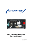
1
F eFiind Fire der PLLUS S Fire Alarm A m Con ntrol Pane el (A AS724 40 – 2 & 4 / AS4 4428 - 3) Ins stallattion, Com mmiss sionin ng & perattion Op MA AN299 94-2 RIGADE RE ESPONSE G FIRE BRIGADE B FIRE BR RESPONS R SE GUIDEGUIDE Resp ponding g to a Fire Acce ess Level 1 The indicator i willl be illumin nated. The applicable a zzone indica ator will also be illuminatted if a Zone e Board is ins stalled otherw wise details of the Loop, Sensor and d Zone es in alarm arre displayed on the LCD as follows. FIRST ALARM: A L1 D D1 Z1 15:31 D.DSC: :Loop 1 Sen nsor 1 Z.DCS: :Zone 1 LAST AL LARM: L4 D4 49 Z5 15:31 D.DSC: :Loop 4 Sen nsor 49 Z.DCS: :Zone 5 Dep pend C PRESS PREVIOUS/NE P NEXT TO VIEW OTHER ALARMS AC:2Z ALM:5 PALM:0 FLT:0 DIS:0 This control is used to ssilence the lo T ocal buzzer. Pressing thiis button will silence the e p panel buzzerr, which sou nds whenev ver there is a fire alarm oor fault. The sound for a f alarm is a steady sou fire und where as s for a fault it is intermitteent. Acce ess Level 2 – Default Access A level when the do oor is opened d. When the alarm a device es are active e (FACP is in the fire ccondition), ac ctivating thiss ccontrol will silence all alarrms excludin ng the Extern nal Alarm devvice. A Activating the e control aga ain, will resou und the previously silence ced alarm dev vices. If a n new alarm iss recognised d whilst the alarm devic ces are “sile enced”, then all alarm devices d shalll resou und. Note:: If Delays to o Outputs have been con nfigured, to in nvestigate th he delayed A Alarm conditio on press the e “Nextt” button and d “Enter” button. Pre evious and Next N controls s are used too scroll the events on the e LCD D. The eve ents being displayed d deepends on the currentt Mode. sele ected view, ie Zone Mode or Device M Wh hen the “SEV VERAL ALA ARMS” indicaator is illuminated, then n mu ltiple fire ala arms are pre esent on the FACP. In order o to view w the alarms the PR REVIOUS an nd NEXT con ntrols are use ed. A Zone or Device D can b be disabled when w in an Alarm A or Fauult condition by pressing g the Disable button. Note: The Alarm A condittion takes precedence p and a no alarm ms must be e present forr using this bu utton to disab ble faults. T This control is used to re eset the FAC CP from the fire f conditionn and to clear the system m fa ault indicatorr. When using the W t Reset bu utton to clear a fire condition, alarm ddevices mus st have been n s silenced first by means off Alarms Sile ence / Resound control. FIRE BRIGADE RESPONSE FIRE BRIGADE RESPONSE GUIDEGUIDE Disabling a Zone / Device Access Level 2 The following methods can be used to DISABLE a ZONE or Device: For Zones: Press then Press for Zone 1 selection. FIREFINDER 17/10/2013 09:00:00 ZONE:1 SELECT ZONE NO. THEN TO OR DISPLAY OR ZONE/DEVICE DISABLE/ENABLE KEY AC:2Z ALM:0 Now Press the PALM:0 FLT:0 DIS:0 . For Devices: Press the then enter Loop number, Press FIREFINDER LOOP:1 then enter device number. 17/10/2013 09:00:00 DEVICE:1 SELECT DEVICE NO. THEN TO OR DISPLAY OR ZONE/DEVICE DISABLE/ENABLE KEY AC:2Z ALM:0 Now Press the PALM:0 FLT:0 DIS:0 . In either case the Disable LED will illuminate disabled information and the screen will display the Loop 1 Sensor 1 MCP L1 D1 Z1 STAT:NORMAL /DISB ZONES DISABLES 1 of 1 AC:2Z ALM:0 PALM:0 FLT:0 DIS:1 TABLE OF CONTENTS Section 1 2 3 4 5 6 7 Page No. About This Manual ............................................................................................................ 1 1.1 Introduction .......................................................................................................... 1 1.2 General Requirements......................................................................................... 1 1.3 References .......................................................................................................... 1 1.4 Symbols ............................................................................................................... 1 Introduction ....................................................................................................................... 2 2.1 System Overview ................................................................................................. 2 2.2 Key Features ....................................................................................................... 2 2.3 Compliance .......................................................................................................... 3 2.4 FACP Configuration Examples ............................................................................ 4 FireFinder PLUS Description ........................................................................................... 5 Placing The Basic System Into Operation ...................................................................... 7 4.1 Unpacking ............................................................................................................ 7 4.2 Anti-Static Precautions ........................................................................................ 7 4.3 Working on the System........................................................................................ 7 4.4 The Cabinet ......................................................................................................... 7 4.5 Cabling Recommendations.................................................................................. 8 4.6 Power Supplies and AC Mains Installation ........................................................ 10 4.6.1 Connecting the Mains Earth ............................................................... 10 4.6.2 Connecting 5 AMP Power Supply ...................................................... 10 4.7 CORRECT Power Up / Turn “ON” Procedure ................................................... 11 4.8 Brigade / PSU Monitor Board ............................................................................ 11 4.8.1 Battery Connections ........................................................................... 13 4.8.2 Auxiliary 27 Volt Power ...................................................................... 13 4.8.3 Monitored Inputs................................................................................. 14 4.8.4 Monitored Outputs .............................................................................. 15 4.8.5 Relay Output Connections ................................................................. 16 4.9 Main Board ........................................................................................................ 17 4.10 Front Panel Board.............................................................................................. 18 4.11 Main CPU........................................................................................................... 19 4.12 Slave CPU ......................................................................................................... 20 4.13 Addressable Dual Loop Termination Board....................................................... 21 4.13.1 Detector loop Isolator Installation ....................................................... 22 4.13.2 Loop Isolator calculator ...................................................................... 22 4.13.3 Loop Open / Short Circuit. .................................................................. 22 FireFinder PLUS Control Panel ..................................................................................... 23 5.1 System Controls ................................................................................................ 23 5.2 System Indicators .............................................................................................. 27 Functions And Menus..................................................................................................... 30 6.1 The Default LCD Display ................................................................................... 30 6.2 LCD Contrast ..................................................................................................... 30 6.3 Accessing Functions and Menus ....................................................................... 30 6.4 Function Menu and Access Levels .................................................................... 31 6.4.1 Forgotten Passwords ......................................................................... 31 The Main Menu ................................................................................................................ 32 7.1 Alarms ................................................................................................................ 32 7.2 Stage 1 Alarms .................................................................................................. 32 7.3 Pre-Alarms ......................................................................................................... 33 7.4 Faults ................................................................................................................. 33 7.5 Disables ............................................................................................................. 34 7.6 Walk Tests ......................................................................................................... 34 7.7 Status ................................................................................................................. 35 8 9 10 11 12 Tools .................................................................................................................. 39 7.8 7.9 Setup.................................................................................................................. 40 7.10 About.................................................................................................................. 41 The Function Menu ......................................................................................................... 42 8.1 Date ................................................................................................................... 42 8.2 Time ................................................................................................................... 42 8.3 Day/Night ........................................................................................................... 43 8.4 Logs ................................................................................................................... 43 8.5 TESTS ............................................................................................................... 44 8.6 I/O ...................................................................................................................... 45 8.7 Global (Network Panels) .................................................................................... 46 8.8 Passwords (Level III) ......................................................................................... 47 8.9 Programming ..................................................................................................... 48 8.9.1 Conv (Conventional) Zone ................................................................. 48 8.9.2 Device................................................................................................. 49 8.9.3 Input.................................................................................................... 50 8.9.4 Output ................................................................................................. 50 8.9.5 Panel Based MCP .............................................................................. 50 8.9.6 Sub Address ....................................................................................... 50 8.9.7 Zone programming ............................................................................. 50 8.9.8 Extra Devices Detected ...................................................................... 52 8.9.9 Mismatch Detected............................................................................. 52 Incoming Fire Alarm Signal............................................................................................ 54 Accessing a Loop, Device or Zone ............................................................................... 55 Modem / Programming / Debug Interfacing ................................................................. 56 Expanding the FACP with Compatible FireFinder PLUS Boards ............................... 57 12.1 Ancillary Services .............................................................................................. 57 12.2 Compatible FireFinder PLUS Boards ................................................................ 57 12.3 Expansion Board ............................................................................................... 58 12.4 8 Zone Conventional Board ............................................................................... 59 12.5 32 Zone Alarm Mimic Card ................................................................................ 60 12.6 8 Way Switch and Indicator Card ...................................................................... 61 12.7 16 Way Input Board ........................................................................................... 62 12.8 8 Way Relay Board ............................................................................................ 63 12.8.1 Internal Relay Board........................................................................... 63 12.8.2 Remote Relay Board .......................................................................... 64 12.9 8 Way Sounder Board ....................................................................................... 65 12.10 4 Way Fire Fan Module ..................................................................................... 66 12.11 4 Way Fan Termination Board ........................................................................... 67 12.12 Bargraph Display Card ...................................................................................... 68 12.12.1 Mechanical ......................................................................................... 68 12.12.2 Front Panel Decal............................................................................... 68 12.12.3 Front Panel Controls .......................................................................... 68 12.13 Communications Extender Board ...................................................................... 69 12.14 SmartTerminal ................................................................................................... 69 12.14.1 Overview ............................................................................................ 69 12.14.2 Mechanical ......................................................................................... 70 12.14.3 Installation & Cabling.......................................................................... 71 12.14.4 Setting the SmartTerminal Address ................................................... 71 12.14.5 Operation ............................................................................................ 72 12.14.6 SmartTerminal Controls and Indicators.............................................. 73 12.14.7 SmartTerminal Screen Format ........................................................... 73 12.15 Agent Release Control....................................................................................... 76 12.15.1 Operation ............................................................................................ 76 12.15.2 Agent Release Module ....................................................................... 79 12.15.3 Local Control Station .......................................................................... 80 12.15.4 Agent Release Termination Board ..................................................... 83 13 14 15 16 17 18 19 20 21 22 23 24 12.15.5 Interface Wiring .................................................................................. 84 12.15.6 Warning Signs .................................................................................... 85 12.16 Occupant Warning Systems .............................................................................. 89 12.16.1 Amplifier Board (25W and 50W) ........................................................ 89 12.16.2 Front Panel Switch and Indicator Module .......................................... 90 12.16.3 Panel Interfacing ................................................................................ 91 12.17 Printer ................................................................................................................ 92 12.17.1 Indicators and Buttons........................................................................ 92 12.17.2 Maintenance ....................................................................................... 93 12.17.3 Printer Connections and Jumpering ................................................... 95 12.17.4 Printer 5 Volt Power Supply ............................................................... 95 Expanding the System through Networking ................................................................ 96 13.1 Networking ......................................................................................................... 96 13.2 Network Interface Card ...................................................................................... 96 13.3 High Level Interface Expander .......................................................................... 98 List of Compatible Devices .......................................................................................... 100 Certification Information .............................................................................................. 101 Maintenance and Troubleshooting Chart ................................................................... 102 16.1 Maintenance .................................................................................................... 102 16.2 Troubleshooting FireFinder PLUS ................................................................... 103 Compatible Devices ...................................................................................................... 104 Address Setting ............................................................................................................. 106 Glossary of Terms......................................................................................................... 107 Definitions ...................................................................................................................... 108 Specifications ................................................................................................................ 109 QUICK REFERENCE GUIDE ......................................................................................... 111 Statement of Compliance ............................................................................................. 112 23.1 Installation Details............................................................................................ 114 Commissioning Test Report ........................................................................................ 115 24.1 Procedure ........................................................................................................ 116 24.2 System Information .......................................................................................... 116 FIREFINDER PLUS S (AUST) INSTALLA ATION,COMM MISSIONING G OPERATIO ON 1 Abou ut This Manual M 1.1 Introduction This manual conttains all the information required to install, comm mission and operate the e FireFinderr PLUS S Fire Alarm Control Pan nel (FACP) a and is only av vailable to and for the usse of personnel engaged d in its installation, commissioniing and operration. 1.2 Generral Require ements The FireFinder PLUS FACP P has been designed and a manufac ctured from high quality commerciall comp ponents so as to comp ply with maj ajor world sttandards. To o ensure thhese standa ards are nott comp promised in any a way insta allation staff and operato ors should; Be qualified d and trained d for the taskk they underttake; Be familiarr with the con ntents of thiss manual prio or to the insttallation, com mmissioning or operation n of a FireFin nder PLUS control c syste em; all times; and Observe an nti-static pre--cautions at a d Be aware that t if a prob blem is enco untered or th here is any doubt d with reespect to the e operationall parameterss of the insta allation the su upplier should be contactted. 1.3 Refere ences ConffigManager PLUS: P Ope eration Manu ual Apollo: Ampac: Dettector / Devicce Manuals Pro oduct Data S heets Australian Stand dard: AS72 240 - 2: 2004 4 AS72 240 - 4: 2004 4 AS44 428 - 3: 2010 0 Con ntrol and Ind icating Equip pment Pow wer Supply E Equipment Fire e Brigade Pa anel 1.4 Symbo ols Important operational in nformation NNote: Configuratio on considera ations Obs serve antista atic precautio ons Mains supp ply earth DANGER mainss supply pres sent Page 1 FIREFINDER PLUS (AUST) INSTALLATION,COMMISSIONING OPERATION 2 Introduction 2.1 System Overview The purpose of the FireFinder PLUS Fire Alarm Control Panel (FACP) is to monitor changes in inputs, report those changes and update selected outputs as programmed. 2.2 Key Features The FireFinder PLUS panel is capable of supporting: Apollo Discovery and XP95 Intelligent Detectors, Multisensor, Photoelectric, Ionisation, Thermal (heat) and CO detectors. Conventional two wire zone detector circuits Multiple input/outputs Agent Release Fan Control High Level Interfaces SmartGraphics EV3000 – Early Warning System Nurse Call SmartTerminal Remote LED mimics Peer to Peer networking Master Slave (Main - Sub) networking Main panel plus Data Gathering Panels networking Figure 1: Typical Application Page 2 FIREFINDER PLUS (AUST) 2.3 INSTALLATION,COMMISSIONING OPERATION Compliance The FireFinder PLUS FACP is approved to AS7240 – 2 & 4 and AS4428 – 3:2010 and includes the following ‘Optional requirements’ as defined by AS7240-2:2004: 7.8 Output to fire alarm devices 7.9.1 Output to fire alarm routing equipment 7.9.2 Input from fire alarm routing equipment 7.10.1 Output type A to fire protection equipment 7.11.1 Delays to outputs – configuration of delays (for item C) 7.11.2 Delays to outputs – control of delays (for item C) 7.12.1 Dependency Type A 7.12.2 Dependency Type B 7.12.3 Dependency Type C 9.3 Fault signals from points 9.9 Output to fault warning routing equipment 10 Disable condition 10.5 Disablement of addressable points 11 Test condition ZB Alarm Acknowledgement Facility ZD Ancillary Control function The FireFinder PLUS PSE includes the following ‘Optional requirement’ as defined by AS72404:2004: 5.5 Battery function check Page 3 FIREFINDER PLUS (AUST) 2.4 INSTALLATION,COMMISSIONING OPERATION FACP Configuration Examples FRONT PANEL CONTROL EARTH STUD EXT +35V CN18 B L2+ L1- CN2 2 CN1 3 CN3 CN15 16 WAY CN2 LOOP COMMS CN2 c + - EXT +35V CN2 1 c 1 a b 1 a b U15 MAINS SWITCH DANGER 240V +VE CN14 4 CN11 ACTIVE A L2+ L1- CN13 -VE NEUTRAL CH16 CN20 D13 GROUND 2 LOOP TERMINATION BOARD CN17 MAIN CONTROL BOARD CH15 SLAVE CPU +V +V EXT +35V SLAVE CPU -V B SLAVE CPU -V (AC) L2+ L1- 1 20 WAY POWER SUPPLY UNIT N/O D14 CN1 SERIAL RELAY BRD OR AGENT TERM BRD OR FAN TERM BRD CN10 PSU MONITOR BRIGADE I/F 27V IN C12 10 WAY CN7 CN6 CN2 + CN21 R17 MODEM CH2 CN4 CN1 CN3 EXPANSION PANEL BZ1 EXPANSION LEDS FRONT PANEL PRINTER CN5 3 WAY N/O C N/C RELAY 3 CN3 CH1 N/O C N/C RELAY 4 CH8 ZD7 - TX1 X- PRINTER C/W MOUNTING PLATE. SGD BAT- BAT+ E. BOARD SW. POWER 0V +27V POWER O/Ps TB10 FAN CONTROL, AGENT RELEASE, OWS CONTROL OR SWITCH & INDICATOR CN3 CN1 + - AUX OUT 1 + POWER AUX OUT 2 CN2 CN4 26 WAY BRIGADE O/P TERM BOARD N/O C N/C RELAY 2 CH8 CH6 N/O C N/C RELAY 1 CH8 CN16 CN8 N(AC) U11 U10 TP3 TH1 L(AC) EXT +35V CPU BOARD RN17 A CN1 CN1 CN1 U14 L2+ L1- U13 POWER RN20 CN2 E. BOARD CONTROL HPCI B A + - S COMMS OUT D C B A CTS COMMS IN D C RTS S RXD - TXD + COM TRX- TRX+ CTS RTS RXD TXD SCRN TB1 TB1 0V +27V PRINTER PSU C/W CABLE COM CABINET BACKPAN VIEW SHOWING MODULES FITTED TO THE BACKPAN AND WIRING DETAILS TB3 TB2 TB3 TB2 CN3 OUT OPTIONAL NETWORKING BOARDS NETWORK INTERFACE CARD NOTE: POSITION MAY VARY AS SHOWN AND IS FOR INDICATION ONLY. TYPICAL FRONT DOOR LAYOUT FOR A FULLY POPULATED PANEL CN2 CN1 CN1 NOTE: PANEL LAYOUT MAY VARY DEPENDING ON CLIENT CONFIGURATION TO BATTERIES Figure 2: Typical Example of a SP1M/SP1X Layout AGENT TERM BRD OR FAN TERM BRD FRONT DOOR AND FRONT INNER DOOR REAR VIEW SHOWING INSTALLED BOARDS ON FRONT INNER DOOR AND WIRING DETAILS FRONT PANEL CONTROL RJ45/8 PIN MAIN CONTROL BOARD MAINS INPUT DANGER 240V EARTH STUD CN2 CH15 2 LOOP TERMINATION BOARD OR 16Z CONVENTIONAL BOARD MAINS SWITCH L(AC) N(AC) CN10 PSU MONITOR BRIGADE I/F (AC) +VE -VE CN 1 GROUND CN 3 NEUTRAL 20 WAY ACTIVE 16 WAY SLAVE CPU 2 SLAVE CPU 3 SLAVE CPU 4 CPU BOARD CH15 -V -V +V +V 10 WAY CN7 ZD7 CN6 C N8 CH2 CN1 PRINTER 16Z CONVENTIONAL BOARD POWER OK CN1 0 RS 485 CO MMS. IN 1+ SLAVE CPU 6 N/O C N/C N/O C N/C N/O C N/C N/O C N/C N/O C N/C RELAY 3 RELAY 1 RELAY 5 RELAY 2 RELAY 4 TB1 + TB2 S COMMS OUT D C B A R TS - A RXD + COMMS IN D C B COM TXD BRIGADE PSU MON. BOARD A UX OUT 2 S + C TS CN1 TB3 X- PRINTER C/W MOUNTING PLATE. SGD E. BO ARD SW. POWER E . BOA RD CO NTRO L HPCI TB3 +27V 0V CN1 CONTROLLER I/F CARD TB2 COM TXD RXD R TS C TS TRX+ TRXSCRN TB1 CN3 NOTE: WIRING MAY VARY DUE TO CLIENT PANEL CONFIGURATION OUT CABINET BACKPAN VIEW SHOWING MODULES FITTED TO THE BACKPAN AND WIRING DETAILS CABINET TO BATTERIES Figure 3: Typical Example of a SP8 Layout Page 4 TB10 NETWORK I/F CARD BLANK OPTIONAL NETWORKING BOARDS NETWORK INTERFACE CARD CONTROLLER INTERFACE CARD. NOTE: POSITION MAY VARY AS SHOWN AND IS FOR INDICATION ONLY. - - CN2 EXPANSION BOARD AUX OUT 1 + CN1 SLAVE CPU 7 SLAVE CPU 8 SLAVE CPU 5 3 WAY BAT- BAT+ 0 V +27V P OWE R O/Ps CN11 C OMM S . CN10 CN1 1 RS 485 CO MMS. OU T 1- 20 WAY BLANK BATT C OMMS FAIL 2 + 23+ 34+ M ONITORED OUT PUTS ANCILLARIES or HOUSING BLANKS C OM M S. AGENT RELEASE MODULE OR FIRE FAN CONTROL MODULE GENERAL INDICATOR CARD POWER SUPPLY UNIT C 1 + 2 + 3+ 4 + MONIT ORED INPUTS RJ45/8 PIN 4- 3 WAY CN3 C N5 FIREFINDER PLUS (AUST) INSTALLATION,COMMISSIONING OPERATION 3 FireFinder PLUS Description The following description does not relate to specific cabinets as the size of each cabinet will vary with the amount of hardware fitted. The heart of the FireFinder PLUS consists of two boards collectively known as the Controller. These boards are the Main Board and the CPU Board. Combining these two boards with a front panel forms the basis for a FireFinder PLUS FACP. A single Controller without an expansion board has the capacity to interface to four (4) Slave CPU’s modules. These Slave CPU’s can be used for Loop Termination Boards. The Main Board has the Slave CPU Board for the first Loop Termination Board and the provision for mounting of up to three additional Slave CPU’s to interface to loops 2 - 4. The Slave CPU’s all have the same software installed and the manner in which they operate is automatically determined by the type of termination or interface board onto which they connect. If the system is to be expanded to have more than four Loop’s an Expansion Board is required. This board contains Slave CPU No. 5 and expansion sockets for three more to interface to loops 6 - 8. This configuration allows for a maximum number of 8 Slave CPU’s that any one Controller can accommodate. BACKLIGHT RESET SW1 MAIN BOARD EXPANSION MODULE CN17 CN15 CN2 C N2 + EXPANSION LEDS RS485 COMMS TO FRONT DOOR BRDS 20 WAY RIBBON 6 7 SLAVE CPU 6 PRINTER CN1 USB USB DEBUG CN2 27VDC IN C N7 EXTRA CONTROLS C N 4 FRONT PANEL INTERNAL SERIAL COMMS PORT EXPANSION LED'S (CN3) CN1 BRIGADE I/F CN6 PSU MONITOR EXPANSION MODULE CN16 KEY SWITCH BZ1 THE MAIN BOARD IS FITTED WITH SLAVE CPU 1 CN10 TO LOOP TERMINATION BRD PRINTER 27V COMMS 3 CN3 EXPANSION PANEL SLAVE CPU 5 ON BOARD CN9 BUZZER OUT CN25 C N2 COMMS1 RS232/MODEM (BOTTOM) LK3 TP1 CN21 0V TP1 CN27 COMMS2 RS232 (TOP) C N8 LK1 DEBUG LK1 DEBUG LK1 DEBUG TP1 RS485 EOL LK2 BUZZER INHIBIT COMMS 2 RS232 TO FRONT KEYPAD (NOT USED IF THE KEYSWITCH PANEL IS A NODE AND EXTRA WITHIN THE SAME CONTROLS PANEL) CN3 8 SLAVE CPU 7 SLAVE CPU 8 C N2 C N2 C N2 CN5 LK1 DEBUG LK1 DEBUG LK1 DEBUG TP1 TP1 TP1 AN EXPANSION BOARD (BRD86FEPB) CAN BE CONNECTED TO FACILITATE UP TO FOUR ADDITIONAL SLAVE CPU'S IF REQ Figure 4: Single Controller Board with Expansion Board Page 5 CN5 INTERNAL PRINTER O/P CN4 NODE ADDRESS 1 27V IN CN2 +5V 123 4 5 6 7 8 NODE ADDRESS SLAVE CPU 2 CN23 MAIN CPU SW2 TERMINATION BOARD SLAVE CPU 3 SLAVE CPU 4 LOOP COMMS EXTERNAL LOOP COMMUNICATION CONNECTS TO NIC CN18 2 NETWORK LOOP CO MMS CN11 RS485 COMMS TO BACKPAN BOARDS CN20 SLAVE 2 CN14 3 CN10 SLAVE 3 CN13 CN26 SLAVE 4 CN100 4 FIREFINDER PLUS (AUST) INSTALLATION,COMMISSIONING OPERATION FireFinder PLUS has an internal RS485 communication bus that allows for various ancillary boards (add on modules) to be connect to the panel. These boards can be used to control and monitor field plant equipment or the addition of an agent release module. Where the system design exceeds the capability of one FireFinder PLUS then other FireFinder PLUS panels can be networked together to provide an expanded system containing multiple boards in a variety of applications. Some of these applications include: A Master / Slave (Main Sub) FACP arrangement (MFACP / SFACP) A Peer to Peer System Use of Data Gathering Panels (DGP’s) SmartTerminal SmartGraphics A Network FireFinder PLUS System supports a combination or all these options on a single network. Each panel on the network is regarded as a “node”. The NETWORK BUS is accessed using a Network Interface Card (BRD86NIC). The network configuration determines whether a NIC is required. Configurations can be; Master / Sub FACP: Where there is one or more FACP’s configured as local panels then each report the status of their associated zones/devices to a MFACP. There is no control between local panels as the MFACP is structured to have full control of the entire system. Peer to Peer: Each FACP user can take control of the entire fire system from any FACP. Data Gathering Panel: The use of this type of panel may be installed where there is a need to have field terminations only at one location and all control is performed by an FACP that is remotely located. SmartTerminal: Provide the user with the ability to monitor the status of designated areas or an entire site as well as execute specific interrogation tasks. SmartGraphics: Is an active graphics system connected to the FireFinder PLUS. Page 6 FIREFINDER PLUS S (AUST) INSTALLA ATION,COMM MISSIONING G OPERATIO ON 4 Placing The Basic Syystem Into Operaation 4.1 Unpac cking Careffully unpack the FireFind der PLUS. The p package sho ould include: FireF Finder PLUS S Fire Alarm Control Pan nel A CD D containing this “Installa ation and Com mmissioning” manual 003 keys 4.2 Anti-S Static Prec cautions To prrevent dama age to compo onents, mod dules and bo oards, anti-static precautiions MUST be b observed d while e performing any task with hin the FACP P. The same e applies to th hose situatedd in the field.. 4.3 Working on the System Prior to o unplugging any conne ector, connecting or disconnecting g any wiring g, removing g or replacing any y module or board, ensu ure that botth the Mains s and Batterries have be een isolated d to prrevent dama age to panell componen ts. 4.4 The Cabinet Feattures: The cabinet is available a in ffour differen nt styles. Each style hass the capabiility of being g eithe er surface or flush mounte ed. With flus sh mounting though t a surrround is required. Norm mally painted d Surf Mist R Ripple. Other colours are available on request. The inner and ou uter door hin nges are mo ounted on the e left-hand sside of the ca abinet which h allow w the doors open o to an an ngle of 100º. A keyed entry is provideed Knocckouts are positioned p on n gland plate es and a cut out is avaiilable on the e rear of the e cabin net to simpliffy cable entryy. Mounting The Cabinett Note: It is reecommendedd the cabinett should be installed i in a clean, dry, vvibration-free e area. Open n the front do oor. Use the e keyhole mo ounting holes s in the top corners c and the two hole es along the e bottom of the un nit to mount it on the w wall. Cables to connect the t system tto its extern nal actuating g devicces are broug ght in through the knocko outs on the to op or bottom of the cabinnet. R 3 mm 12 mm R 6mm m. Tap lightly around a the rim of the kn nockout Fig gure 5: Exam mple SP1 Ba ck Pan Moun nting Hole & Removing K Knockouts Page 7 FIREFINDER PLUS (AUST) 4.5 INSTALLATION,COMMISSIONING OPERATION Cabling Recommendations Conventional Zones Cabled in red Twin Plastic Sheath (TPS), Fire rated Radox or approved equivalent. Analogue Loop Two core cable. The minimum cable size is 0.75mm2, the maximum loop resistance is 50 ohms and the maximum loop distance is 2km. RS 485 Network Single twisted pair screened (2 core) cable originating from FACP extending through the protected areas and returning to the FACP. Cable Specifications Capacitance of 100 Pico farads per metre or less Resistance of 100 milliohms per metre or less Impedance of loop typical 100 to 120 ohms Maximum distances between modules 1.2km providing cable meets above specifications. Recommended cable type Belden 8132 or 9842 (non fire rated) Radox FR Communication 0.75mm 1 pair (fire rated) x 2 SmartTerminal Single twisted pair shielded cable (2 core) plus 2 core power, or local supply. Maximum distance between from the last SmartTerminal and the FACP is 1.2km. LED Mimic (RS485) Single twisted shielded cable (No return loop) plus 2 core power or local supply. Maximum distance between each LED repeater card and FACP is 1.2km. Recommended Cable Type Hartland HC2335 Belden 9841 Radox FR Communication Fire Alarm Bell Connection Two core 1.5mm2 PVC sheathed MIMS (Mineral Insulated Metal Sheathed) to the bell location. Brigade Connection via Telecom Two core 1.5mm² PVC sheathed MIMS from the FACP to the Telecom MDF. RJ45 Multi-drop Serial Port 8 core Flat cable Power Supplies / AC Mains The requirement for the mains supply to the FACP is fixed wiring, using three core cable (no less than 0.75mm² and no more than 2.5mm² ) or a suitable three conductor system, fed from an isolating switch fuse spur, fused at 3A. This should be secured from unauthorised operation and be marked 'FIRE ALARM: DO NOT SWITCH OFF. The Mains supply must be exclusive to the FACP. Page 8 FIREFINDER PLUS S (AUST) INSTALLA ATION,COMM MISSIONING G OPERATIO ON Co ommon Pow wer Supply Features F &S Specificatio ons Sw witch Mode Design D Over voltage e protection Hig gh efficiencyy, low working temp. High efficien ncy; low ripplle noise Un niversal AC input/ full ran nge Soft start with limiting AC C surge current Sh hort circuit/ over load Remote con ntrol on/off (ooption) Bu uilt in EMI Filter and PFC Circuit Over temp. protection (ooption) Inp put Voltage: Inp put Freq PF FC 85 to 264 4 VAC 47 to 63H Hz. 0.95~230 0VAC Tolerance at a 27V Load Regulation Line Regula ation +/- 1% +/- 0.5% +/- 0.5% Po ower Supply y Specificatiions Ty ype No Outpu ut Tolerance e R&N Efficie ency PS SU1888 PS SU1890 33 30-0015 1% 1% 1% 150mV 150mV 240mV 84% 87% 86% 27V @ 5.6A 24V @ 14A 27VDC C @ 22A Important: Under no circumstanc ces should the t FireFind der PLUS be b operated d out the Powe er Supply PC CB correctly mounted in the enclosurre and the reetaining scre ews securelyy witho tighte ened. Page 9 FIREFINDER PLUS (AUST) 4.6 INSTALLATION,COMMISSIONING OPERATION Power Supplies and AC Mains Installation Generally the AC Mains will be connected to either a 5 Amp, 14Amp or 22 Amp 27 volt supply. These supplies will be either mounted in the upper or lower right hand corner of the cabinet with the Brigade Board mounted in close proximity. The wiring should enter the cabinet through the nearest knockout entry hole on that side. Refer to Figures 6 - on for the wiring and fusing details for each supply. 4.6.1 Connecting the Mains Earth All earth cabling shall be terminated to the panel Chassis Earth Terminal in a star configuration. The earth cable closest to the cabinet body shall have an M4 SPW beneath the lug then an M4 SPW and M4 nut. Each additional earth cable shall be terminated with an M4 SPW and M4 nut. An additional M4 nut and M4 SPW are fitted to the Chassis Earth Terminal for installers to connect their Mains Earth. CHASSIS EARTH TERMINAL Note: M4 Nut * M4 Shake Proof Washer * M4 Nut M4 Shake Proof Washer * Extra M4 Nut and M4 SPW are provided finger tight on the Earth bolt. Earth Cable M4 Nut Earth Cable M4 Shake Proof Washer Figure 6: Panel Earthing 4.6.2 Connecting 5 AMP Power Supply Output Voltage: 27.4 Volts. FUSE Rating: 2 Amp 3AG Slow Blow Mains Cable: should be no less than 0.75mm² Figure 7: Mains Power Connection to the 5 AMP Power Supply Page 10 FIREFINDER PLUS (AUST) 4.7 INSTALLATION,COMMISSIONING OPERATION CORRECT Power Up / Turn “ON” Procedure Once all the field devices are installed and the wiring has been correctly terminated the FireFinder PLUS is ready to turn on. For reliable power up it is essential the following procedure be followed; 4.8 1. Turn the Mains power on, THEN 2. Connect the batteries observing correct polarity. 3. The green power on LED should be illuminated. Brigade / PSU Monitor Board The Brigade / PSU Monitor Board (BRD86BPSC) monitors and controls the power supply, battery charging, monitored / un-monitored inputs, outputs and the 5 relay outputs. Connections TB(x) TB1 TB2 TB3 TB4 TB5 TB6 TB7 TB8 TB9 TB10 CN(x) CN1 CN1 CN3 CN4-8 Function Aux Out x 2 Relay 1 Relay 2 Relay 3 Relay 4 Relay 5 Monitored Outputs x 4 Monitored Inputs x 4 Battery Out / 27VDC PSU IN External Board / SW POWER Type of Output Protected 1 Amp Voltage Free Contacts 1 Amp Voltage Free Contacts 1 Amp Voltage Free Contacts 1 Amp Voltage Free Contacts 1 Amp Voltage Free Contacts 24Vdc EOL Switched Negative, EOL Protected Function JTAG SGD External Board Controls Power Out Type of Output 1 Amp ( protected ) Relay Information Voltage Free contacts are rated at 1A @ 30V Back EMF Protection Inductive loads fitted to the Brigade PSU Monitor Board MUST be fitted with “Flyback” diodes at the load for back EMF protection. Transient Protection Recognised transient line protection methodologies at the FACP and the load MUST be considered when connecting any control devices to the outputs be they in close or remote. Page 11 JTAG CN2 U6 D9 C34 EOL D10 C35 CN11 COMMS. CN10 C58 C56 N1236 M16 CN10 RS485 COMMS. IN ZD5 1- To CN20 of the Main Controller Board 22/09/09 TB8 TB7 U7 BRD86BPSC4- 2 + 2- 3 + 34+ MONITORED OUTPUTS D11 C36 1+ U5 RL5 M15 RL4 M7 RL3 Q5 R108 RL2 L7 L8 TH8 CN6 RL1 M11 D7 CN5 E. BOARD CONTROL BAT- BAT+ 0 V +27V TB10 SGD E. BOARD SW. POWER CN3 CN1 + TH2 TH4 TH7 L9 TH1 Q8 TB3 TB2 M12 M1 AUX OUT 1 AUX OUT 1 CN7 HSNK2 TH5 M3 TB1 AUX OUT 2 - + - AUX OUT 2 CN8 M13 M2 2 x AUX OUT 27VDC @ 2A TH9 R103 M5 M4 Alarm Relay L6 M14 M6 Fault Relay 1 T1 C43 M8 Warning System Alarm U2 HSNK1 TB5 M9 R75 TB6 Isolate Relay Note: N/C C N/O Denotes Voltage Free Contacts N/C = Normally Closed C = Common C N/O = Normally Open U8 ZD6 M10 Batt Fail Relay (Normally Energised) TB4 Relays are Programmable Default Setup Shown ZD2 ZD1 Sounder CN11 RS485 COMMS. O UT ZD7 N/O C N/C N/O C N/C N/O C N/C N/O C N/C N/O C N/C RELAY 3 RELAY 1 RELAY 5 RELAY 4 RELAY 2 EOL 10K Ohms COMMS FAIL ZD4 ZD3 MONITORED OUTPUTS ( EOL Required ) POWER OK BATT FLT. ZD8 4- Note: If a diode is NOT fitted internally to a bell / sounder a diode MUST be fitted as shown - fit 1N4004 or similar Bell EOL 10K Ohms 1+ 2+ 3+ 4+ C MONITORED INPUTS CN12 MONITORED INPUTS ( EOL's Required ) COMMS. LK1 EXT TEMP INSTALLATION,COMMISSIONING OPERATION ETH MON EN FIREFINDER PLUS (AUST) TB9 HPCI CN4 to 8 Supplies Regulated +27VDC to Internal Boards 1A / Connector CN4 POWER O/Ps +27VDC from PSU N/C Battery 1 12 Volts N/O + - + - Battery 2 12Volts Figure 8: Brigade / PSU Monitor Board Layout Note: When connecting to the Brigade PSU Monitor board transient and “Flyback” (Back EMF) protection methodologies MUST be applied. Page 12 FIREFINDER PLUS (AUST) 4.8.1 INSTALLATION,COMMISSIONING OPERATION Battery Connections A FireFinder PLUS requires two (2) 12 volt batteries (TB9). The batteries should be placed into the bottom right hand side of the cabinet. A red and black lead coming from TB1 on the Brigade Board will be clearly seen in the same area, this lead is to be connected to the batteries red to positive and black to negative once the system is operating on Mains supply. Battery size is dependant on system configuration and can vary from 12 AHr to over 100 AHr. JTAG E TH M ON E N CN2 BATT FLT. CN11 D11 C36 D10 C35 U6 D9 C34 COMMS. BRD86BPSC4- U8 U7 CN10 RS485 COMMS. IN M16 ZD7 ZD2 CN10 C58 C56 N1236 ZD4 ZD3 ZD6 ZD1 22/09/09 TB7 CN11 RS485 CO MMS. O UT EOL 2 + 2 - 3 + 34+ MONITORED OUTPUTS POWER OK COMMS FAIL ZD8 4- TB8 0 V +27V BAT- BAT+ 1+ 2+ 3+ 4+ C MONITORED INPUTS CN12 COMMS. L K1 EXT TEMP Note: Refer to Ampac’s battery calculation tool to calculate the required battery size. 1+ 1- ZD5 U5 RL5 M9 RL4 RL3 TH5 L7 M3 M12 L8 TH8 CN6 RL1 M11 D7 TH4 TH7 L9 TH1 Q8 CN5 + TH2 TB1 AUX OUT 2 - + - M1 AUX OUT 1 Battery 2 12Volts BAT- BAT+ 0 V +27V E. BOARD SW. POWER CN3 CN1 - CN7 HSNK2 SGD TB10 - TB2 Q5 R108 RL2 + + CN8 M13 M4 TB3 - + Battery 1 12 Volts TH9 R103 TB4 M5 M2 - + L6 M14 M6 +27VDC from PSU 1 T1 C43 M7 HSNK1 TB5 TB9 BRIGADE BOARD U2 M15 M8 R75 TB6 N /O C N/C N/ O C N /C N/ O C N/C N/ O C N/C N/ O C N/C RELAY 3 RELAY 1 RELAY 4 RELAY 5 RELAY 2 M10 E. BOARD CONTROL TB9 CN4 PO WER O/Ps HPCI +27VDC from PSU TB9 is located on the bottom right hand side of the board + Battery 1 12 Volts - + - Battery 2 12Volts Figure 9: Battery Connections to the Brigade / PSU Monitor Board 4.8.2 Auxiliary 27 Volt Power LK1 ETH MON EN JTAG CN2 BATT FLT. CN11 COMMS. C58 C56 N1236 U6 D9 C34 M16 CN10 CN10 RS485 COMMS. IN COMMS. D10 C35 EOL D11 C36 ZD6 ZD1 22/09/09 TB7 U8 U7 ZD7 ZD2 1+ 1- ZD5 U5 RL5 RL4 M7 TH9 CN8 Q5 R108 RL3 M5 R103 M13 RL2 CN7 HSNK2 TH5 L7 M3 M2 HSNK1 M12 L8 TH8 N/O C N/C RELAY 1 CN6 RL1 M11 D7 CN5 TH4 TH7 L9 TH1 TH2 + AUX OUT 1 TB1 AUX OUT 2 - + - M1 Q8 TB4 L6 M14 N/O C N/C N/O C N/C RELAY 3 RELAY 2 TB3 1 T1 M4 TB2 BRIGADE BOARD C43 M6 TB1 is located in the lower left hand side of the board U2 M15 R75 TB6 M9 M8 TB5 2 X LIMITED 2A AUX POWER OUTPUTS N/O C N/C N/O C N/C RELAY 4 RELAY 5 M10 E. BOARD SW. POWER E. BOARD CONTROL BAT- BAT+ 0V +27V TB10 SGD CN3 CN1 AUX OUT 1 + - + - AUX OUT 2 CN11 RS485 COMMS. OUT BRD86BPSC4- 2+ 23+ 34+ MONITORED OUTPUTS ZD4 ZD3 TB1 POWER OK COMMS FAIL ZD8 4- TB8 1+ 2+ 3+ 4+ C MONITORED INPUTS CN12 EXT TEMP Two (2) 1 Amp outputs are available from TB1 terminals 1+ (plus) and 2- (minus) or 3+ and 4- on the Brigade Board. It is important to note these outputs are short circuit monitored. CN4 POWER O/Ps HPCI +27VDC from PSU Battery 1 12 Volts Figure 10: Auxiliary 27VDC Power Output Page 13 + - + - Battery 2 12Volts FIREFINDER PLUS (AUST) 4.8.3 INSTALLATION,COMMISSIONING OPERATION Monitored Inputs Four independently monitored inputs (TB8) are provided and can be configured for a variety of uses. Manual Call Point (MCP) – if activated the FACP will go into alarm. Connected to the MCP on the front of the FACP. Class Change – if activated all Alarm Devices/Sounders and Alarm Device/Sounder Outputs in Sounder Group 1 are turned on. External Fault – if activated the FACP will indicate a Fault condition Ancillary Disable - if activated, the FACP’s “DISABLED” and ANC OUTPUT STATUS LEDs will both be turned on. Note that this event is used to indicate an ancillary/auxiliary disablement or a door-opened condition if a door switch is fitted. It also activates any Relays on the Brigade board configured as “Isolate” relays and affects the Brigade Board’s “Aux/Anc” outputs based on their “normally energised” settings. Evacuate – if activated the FACP goes into Evacuation. Sounder Silence – if activated all activated sounders are silenced. Reset – if activated a Master Reset is initiated. Fire/Feedback - if activated, the FACP’s “Fire Output On” LED will flash (AS7240.2 Clause 7.9.2). Note that this is a latched condition and will only be cleared a “Master Reset” command from the FACP. The default configuration types for the inputs are as follows: Input 1 – MCP Input 2 – Evacuate Input 3 – External Fault Input 4 – Reset The inputs have been designed to operate with a programmable EOL of 3K3Ω, 10KΩ 22KΩ or Unmonitored (no EOL) the 10K EOL is the default. The normal and active ranges change according to the end of line selected. ETH MON EN CN11 COMMS. C58 EOL CN10 BRD86BPSC4- D9 C34 M16 22/09/09 TB7 C56 N1236 TB8 42+ 23+ 34+ MONITORED OUTPUTS U6 CN10 RS485 COMMS. IN 11+ RL5 RL4 TH9 CN8 M13 Q5 R108 RL3 R75 RL2 CN7 HSNK2 TH5 L7 M3 M2 HSNK1 M12 L8 TH8 CN6 RL1 D7 CN5 L9 TH4 TH7 TB1 AUX OUT 2 - + - M1 Q8 TB5 TB4 L6 M14 M5 M4 TB3 1 T1 M6 TB2 BRIGADE BOARD C43 M15 M7 R103 TB6 N/O C N/C N/O C N/C RELAY 4 RELAY 5 M9 U2 + TB8 / C D10 C35 U5 M8 AUX OUT 1 SGD E. BOARD SW. POWER E. BOARD CONTROL BAT- BAT+ 0V +27V TB10 4K7 TO D11 C36 ZD5 M10 CN1 EOL 10K Ohms U8 U7 ZD7 ZD6 ZD1 TB8 CN11 RS485 COMMS. OUT ZD8 ZD2 N/O C N/C N/O C N/C N/O C N/C RELAY 3 RELAY 1 RELAY 2 TB8 / 1+, 2+, 3+ or 4+ (EOL depends on config) DBA / MCP BATT FLT. ZD4 ZD3 TB11 POWER OK COMMS FAIL M11 TB8 / C CN12 TH1 TO CN2 TH2 Door Switch TB8 / 1+, 2+, 3+ or 4+ (Config set to "unmonitored") JTAG 1+ 2+ 3+ 4+ C MONITORED INPUTS Door Switch is Open for Normal Operation and not Monitored C 1+ 2+ 3+ 4+ Note: LK1 COMMS. TB8 location EXT TEMP Sensed Condition Short circuit Fault Active condition Normal Open circuit Fault CN3 Line Resistance (10K EOL) 0Ω– 150Ω 470Ω – 4KΩ 8KΩ – 15KΩ 20KΩ to ∞ CN4 POWER O/Ps HPCI +27VDC from PSU Battery 1 12 Volts Figure 11: Inputs DBA / MCP and Door Switch Wiring Page 14 + - + - Battery 2 12Volts FIREFINDER PLUS (AUST) 4.8.4 INSTALLATION,COMMISSIONING OPERATION Monitored Outputs Four independently monitored and controlled outputs (TB7) are provided and can be configured for a variety of uses. Alarm Devices - activated when any of its four sounder groups is active. (AS7240.2 Clause 7.7 and 7.8). The output is turned off during an Alarm (sounder) disable or Alarm (sounder) silence condition. ASE – (Australia Firefinder Plus Only) Fire/FARE – activated by alarm condition (AS7240.2 Clause 7.7 and 7.9.1). The output is turned off during a FIRE disable condition. Ancillary - activated on device alarm conditions. The Output is turned off during an Ancillary disable condition. Warning System - activated on evacuation and device alarm conditions. The output is turned off during an Alarm (sounder) disable or Alarm (sounder) silence condition. Fault - activated on all fault conditions (AS7240.2 Clause 9.9). The output is turned off during a FAULT disable condition. General Purpose – activated via the Configmanager “Function” programmed logic. External Alarm Devices - activated when any of its four sounder groups is active. (AS7240.2 Clause 7.7 and 7.8). The output is turned off during an Alarm (sounder) disable or Alarm (sounder) silence condition. These monitored switched outputs, supply a nominal 24VDC, at up to 1 Amperes. Monitoring is for short, open and earth faults when the output is OFF. The outputs have been designed to operate with a programmable EOL of 3K3Ω, 10KΩ 22KΩ or Unmonitored (no EOL) the 10K EOL is the default. Line Impedance (10K EOL) 0Ω– 50Ω 50Ω – 150Ω 150Ω – 15KΩ 15KΩ – 40KΩ 40KΩ to ∞ Reported Condition Short circuit Fault Indeterminate: Maybe reported as shorted or normal Normal Indeterminate: Maybe reported as normal or open circuit Open circuit Fault D9 C34 CN11 CO MMS. CN10 C58 M16 22/09/09 41+ 1- ZD5 U5 RL5 TH9 Q5 R108 CN8 R103 M5 M13 RL2 C N7 HSNK2 TH5 L7 M3 HSNK1 M12 L8 TH8 CN6 RL1 M11 D7 CN5 TH4 TH7 L9 TH1 + TH2 TB1 AUX OUT 2 - + - M1 Q8 TB5 RL4 L6 M14 RL3 TB4 1 T1 M4 TB3 BRIGADE BOARD C43 M15 M7 M6 TB2 U2 R75 TB6 M9 M8 E. BOARD SW. POWER E. BOARD CONTROL BAT- BAT+ 0 V +27V TB10 SGD CN3 CN1 Note: If a diode is NOT fitted internally to a bell / sounder a diode MUST be fitted as shown - fit 1N4004 or similar CN 10 RS485 CO MMS. IN CO MMS. U6 EOL D10 C35 BRD86BPSC4- D11 C36 ZD6 M10 AUX OUT 1 1+ 1- U8 U7 ZD7 ZD2 M2 Warning System CN1 1 RS485 CO MMS. O UT ZD8 N/ O C N/C N/O C N/C N/O C N/ C N/O C N/ C N/O C N/ C RELAY 3 RELAY 1 RELAY 2 RELAY 4 RELAY 5 EOL 10K Ohms C56 N1236 TB8 C 1 + 2+ 3 + 4 + MONI TORED INPUTS BATT FLT. ZD4 ZD3 TB7 4+ 42+ 2- 3+ 3- Sounder EOL 10K Ohms POWER OK COMMS FAIL ZD1 TB7 CN2 CN12 TB7 Location Bell JTAG ETH M ON EN LK1 2 + 2- 3 + 34+ MONITORED OUTPUTS + / - are monitored 1A outputs. Un-used O/P's must be terminated in 10K Ohms EOL EXT TEMP Warning systems and sounders are connected to the Brigade / PSU Monitor Board as shown below. If more sounders are required, the Sounder / Bell Control Board must be used. C N4 POWER O/Ps HPCI +27VDC from PSU Battery 1 12 Volts Figure 12 Connecting a Bell / Sounders Page 15 + - + - Battery 2 12Volts FIREFINDER PLUS (AUST) 4.8.5 INSTALLATION,COMMISSIONING OPERATION Relay Output Connections Five “voltage free” relay outputs (TB2 – TB6) are provided and can be configured for a variety of uses. Alarm - activated on device alarm conditions and “Function” programmed logics. The relay is turned off during a ALARM disable condition. Sprinkler - activated on device alarm conditions and “Function” programmed logics. Fault - activated on all fault conditions and “Function” programmed logics. The relay is turned off during a FAULT disable condition. Isolate - activated on all isolate conditions and “Function” programmed logics. Battery Fail - activated on battery fail conditions and “Function” programmed logics. Mains Fail - activated on a mains power fail condition and “Function” programmed logics. Warning System - activated on evacuation, device alarm conditions and “Function” programmed logics. If the activation of this relay is due to an evacuation condition, then the relay is turned off during an Alarm (sounder) disable or Alarm (sounder) silence condition. Ancillary - activated on device alarm conditions. General Purpose - activated via “Function” programmed logics Relay Switching Characteristics These outputs have been designed to be able to switch predominately resistive loads as listed below. Switching voltage 30VDC 24VAC 50VDC 40VAC Maximum switching current 1A 1A 250mA 250mA ET H MON EN BATT FLT. D10 C35 U6 D9 C34 CN11 C OMMS. CN10 C58 C56 EOL D11 C36 C N 10 RS48 5 CO MMS. IN M16 ZD7 ZD2 ZD6 ZD1 22/09/09 TB7 U8 U7 BRD86BPSC4- ZD8 ZD5 1- NO CC NC NO CC NC NC NO NC NO C N 11 RS48 5 COMMS . OUT 1+ NO CC NC NO CC NC NC NO NC NO POWER OK COMMS FAIL ZD4 ZD3 NO C NC CN2 N1236 TB8 ISOLATE 1 + 2+ 3+ 4 + C MONITORED INPUTS EWIS 4- FAULT JTAG CN12 2+ 2- 3+ 34+ MONITORED OUTPUTS FIRE BATT FAIL LK1 C OMMS. Relays are Programmable. Default Setup Shown EXT TEMP The default relay contacts are connected as shown below. U5 RL5 1 Q5 R108 M12 L7 L8 TH8 CN6 RL1 M11 D7 CN5 TH4 TH7 L9 TH1 TB1 AUX OUT 2 - + - M1 AUX OUT 1 + NC CN7 HSNK2 TH5 TH2 TB2 M2 TB2 to TB6 are located on the lower to mid left hand side of the board CN8 M13 M3 Q8 TB6 TH9 R103 M5 HSNK1 TB5 RL4 RL3 TB4 TB5 L6 M14 R75 TB6 T1 RL2 TB4 TB3 TB3 BRIGADE BOARD C43 M4 SGD E. BOARD SW. POWER E. BOARD CONTROL BAT- BAT+ 0 V +27V TB10 TB2 U2 M15 M7 M6 CN1 C M9 M8 CN3 Note: 1A Un-monitored Voltage Free Conacts: NO: Normally Open NC: Normally Closed C: Common N/O C N/C N/O C N/C N/O C N/C N/O C N/C N/O C N/C RELAY 3 RELAY 1 RELAY 4 RELAY 5 RELAY 2 M10 CN4 POWER O/Ps HPCI +27VDC from PSU NO Battery 1 12 Volts Figure 13: Relay Outputs Page 16 + - + - Battery 2 12Volts FIREFINDER PLUS (AUST) 4.9 INSTALLATION,COMMISSIONING OPERATION Main Board The Main Board (BRD86MBA) carries the devices for interconnecting to all the other Boards, a buzzer for auditory indication, the backlight power supply for the LCD and CPU Reset. The Main CPU is mounted on this board and connected to it by CN11. The main connection board then provides interfacing to: Up to 3 Slave CPU’s (Slave CPU 1 is onboard) A printer A Modem An Expansion Panel An Internal serial bus An External communication bus. Connections CN1 CN2 CN3 CN4 CN5 CN6 CN7 CN8 CN9 CN10 CN11 CN12 CN13 CN14 CN15 CN16 CN17 CN18 CN19 CN20 CN21 CN22 CN23 CN24 CN25 CN26 CN27 CN28 Extra Control (Not Fitted) Expansion Panel Expansion LED’s (Not Fitted) Front Keypad Printer Key Switch (Not Fitted) Brigade Output Modem and RS232 Comms Ext Buzzer Output (Not Fitted) Slave CPU output 1 Main CPU LCD Graphic Slave CPU connection Slave CPU connection R1 C2 C6 HY1 C7 D1 C3 Slave CPU connection Printer 27VDC Out To LCD Backlight supply External Loop Communication LCD Characters RS485 Communications Port 1 RS485 Communications Port 2 To LCD Backlight supply Slave CPU Debug (Not Fitted) Jtag Programming Slave CPU1 (Not Fitted) USB Programming 27VDC In Comms 2 RS232 27VDC In (not fitted) R4 BRD86MBA4- R5 30/06/10 BACKLIGHT R2 Q6 C1 C4 D2 C15 C12 R8 R9 R11 LCD BACKLIGHT INVERTER CHINESE GRAPH R13 LCD TP69 RN1 CN14 SLAVE 3 CN20 U7 CN15 SLAVE 2 C21 C20 2 U8 C27 CHAR LCD C28 U35 R18 R67 R65 LK1 U16 TP3 C33 U20 TP4 Q2 CN19 C31 C36 C34 R66 U17 RN2 SW2 X1 Q8 U22 R22 C43 C45 C44 U21 R23 U23 CN23 ZDN1 C49 C42 R21 C41 U19 D6 C40 C38 C39 D5 C46 SLAVE 1 DEBUG C48 RN5 R24 R26 D7 D8 TP5 C54 CN24 R31 C56 R33 C59 C62 C65 C67 R35 C63 R36 R37 C66 R38 R32 R34 R39 R48 C68 U27 C37 R51 C74 U36 D9 RN8 RN9 TH1 R50 CN26 EXPANSION PANEL R52 C77 CN9 C79 R53 LK3 R57 CN21 BUZZER INHIBIT C83 C78 C80 D16 D17 RN18 BUZZER OU T RN17 U32 ZDN2 EXPANSION LEDS CN3 D15 RN10 RN19 RN11 D12 CN6 R60 RN12 CN7 R61 RN14 FRONT PANEL RN15 U34 CN5 C84 EXTRA CONTROLS CN1 Figure 14: Main Board Layout with no Main CPU or Slave CPU’s Page 17 RN13 U30 R59 KEY SWITCH CN4 BZ1 USB U33 CN16 D14 D13 CN25 PRINTER 27V C81 U31 RN16 D11 C82 + CN8 C89 0V CN2 R49 RN7 COMMS2 RS232 (TOP) COMMS1 RS232/MODEM (BOTTOM) R55 R58 C90 RN6 Q3 Q5 RS485 EOL R56 CN27 R64 C72 Q4 LK2 C91 COMMS 2 RS232 EXPANSION MODULE R19 R25 D10 U29 C19 +5V R40 C69 C71 C73 C75 C76 R54 C85 C87 C86 R47 R46 R41 R43 R45 R44 R42 CN10 C55 C58 C70 U28 R20 R30 R29 C52 JTAG C61 27V IN R28 C51 C50 TP6 C57 U26 PRINTER 1 27V IN CN26 U24 R27 C53 C64 C60 PSU MONITOR BRIGADE I/F U25 CN28 1 2 3 4 5 6 7 8 C35 U18 C88 DEBUG C32 CN18 U10 U15 U14 RN3 U13 RN4 C26 C25 NODE ADDRESS R17 U12 U11 TERMINATION BOARD C24 NETWORK LOOP COMMS 3 C30 C47 EXPANSION MODULE CN19 CN12 Q1 C22 NON-CHINESE GRAPH LCD CN12 U6 D3 U2 4 CN11 C23 U5 U4 C17 CN100 D4 C29 CN17 R63 CN13 SLAVE 4 R15 R16 C18 U9 R62 C11 C10 N1236 R12 U3 R14 L2 C9 C14 C13 L1 CN22 C16 SW1 RESET U1 R7 R10 R6BACKLIGHT C5 C8 R3 FIREFINDER PLUS (AUST) 4.10 INSTALLATION,COMMISSIONING OPERATION Front Panel Board The Front Panel Board (BRD86FPB) provides the buttons used to control the FACP as well as all LED indications. All LED’s are surface mounted and the buttons are embedded within the board. The LCD is viewed / protected by a clear Perspex screen. Connections CN2 To CN4 Main Board C1 C18 D1 R1 D2 R2 D3 Q1 R31 R3 D18 R32 D19 R33 D20 D10 D4 R4 D11 D12 D13 D5 R34 R5 D6 R6 D7 R7 D8 R8 D14 D16 R23 R29 D17 D21 R36 D23 R37 D24 R38 D25 R39 D26 R40 D27 D22 R26 D9 R35 R9 C14 U4 R50 U6 C4 U2 R28 R25 C5 BRD86FPB4- U5 C15 C13 R30 11/08/10 U3 N1236 R24 C6 R27 D28 C11 R41 U8 R42 C9 C10 C12 U7 R43 C19 R46 R45 R44 C7 C16 C23 C8 R10 R14 D15 C17 CN2 R16 CN1 L4 R47 L3 L1 C3 L8 C21 L6 R19 C2 L7 R18 L5 R17 R15 R20 R22 C20 R12 R13 L2 R11 KEYSWITCH R21 D30 Q2 U1 C22 KEYSWITCH Figure 15: Front Panel Board Page 18 FIREFINDER PLUS (AUST) 4.11 INSTALLATION,COMMISSIONING OPERATION Main CPU The Main CPU (BRD86MCPU) holds the main central processing unit including the Application software and Configuration settings for the FACP. The Main CPU is a 4-layer surface mount board The processor runs at 60MHz. 16Mbytes of FLASH 32/64 Mbytes SDRAM USB To Main Board CN11 R1 R2 U4 C2 R9 R4 R6 R3 C8 Q1 C7 C6 USB R8 C4 C5 U1 CN1 R7 ZDN1 R5 C1 C3 R10 Q2 R11 R30 U3 C10 R28 U6 U7 C11 U11 R29 U5 U10 U9 C18 D1 C20 C16 ZDN2 C19 C21 X1 C13 C12 C14 CN2 C9 C15 U2 C17 R12 C22 R13 X2 R14 C23 D2 U8 C33 C32 R16 C31 C34 R21 R20 C27 ZDN3 R19 C30 C28 D3 R18 U13 R17 C25 C29 C24 U12 C26 R15 Q3 C35 U14 C42 C40 C38 C39 C36 R25 C43 D4 R23 R26 R24 C41 C37 R22 U15 C45 R27 C44 U16 0V Figure 16: The Main CPU Board PCB Layout Page 19 + Connections CN1 CN2 FIREFINDER PLUS (AUST) 4.12 INSTALLATION,COMMISSIONING OPERATION Slave CPU The Slave CPU (BRD86SCPU) provides the interfacing signals and I/O’s required to allow the FACP to connect / communicate to a variety of termination boards. A single chip micro controller U7 controls all operations of the FACP Slave CPU. This device contains the control program within Read Only Memory (ROM). Automatic Termination Board Sensing A unique feature of the Slave CPU is its ability to automatically sense the type of board it is connected to without the user having to configure the board to suit. Connections CN2 CN3 To Loop Termination Board To Main Control Board BRD86SCB3C3 C4 R2 C5 LK1 D3 DEBUG U3 U1 R1 C1 Q2 R7 C32 C34 C35 R25 C36 C37 X1 Figure 17: Slave CPU Board Page 20 U5 TP1 R13 R8 R10 R27 R26 C23 C13 C33 JTAG TP3 TP2 D2 C14 C15 C16 C17 C18 C19 C20 C21 C12 CN4 CN1 TP4 R4 U7 R12 R11 U2 C9 R6 RN1 TP5 C8 R14 C11 U6 R5 U4 R24 C10 D1 COMMS C7 Q1 CN3 C31 C6 C27 C2 CN2 FIREFINDER PLUS (AUST) 4.13 INSTALLATION,COMMISSIONING OPERATION Addressable Dual Loop Termination Board The Addressable Dual Loop Termination Board (BRD86DLTB) acts as the interface between the external addressable devices and the control and monitoring functions of the FireFinder PLUS. Each board provides terminations for two loops and can be used with the Apollo range of detectors. One slave CPU is required per loop. Note: Apollo devices L2 is +ve (positive), L1 is -ve (negative) AMPAC strongly recommend that the LoopManager test set is used to check that the Apollo loop has been correctly installed and commissioned before connecting it to the FireFinder PLUS. Loop Parameters 126 Apollo Devices (i.e. maximum address range) When using Alarm Acknowledgement Facility’s (AAF’s) a max of 50 per Loop 500mA Current Max S/C protection circuitry activates at approximately 650mA Maximum length 1.2km Note: To achieve full current, the Loop Trip current in Loop Parameters needs to be set to 300mA (ConfigManager PLUS) R4 C3 Q1 ZD17 C38 R108 R106 R113 Q28 C66 C62 R121 R122 R120 C78 C79 D20 C80 C102 R183 C106 U25 CN3 CN4 C104 C92 R172 R171 C88 R161 C91 R170 0V C105 D22 - - + - + - POWER R179 R178 D21 R184 U24 R156 C96 R180 R181 -R R144 U20 +40V C98 U26 C109 C108 C103 C107 R169 R168 R167 R166 R165 C89 R164 C90 R175 TRI WAVE BRD86DLTB2+12V +5V C100 C101 N1236 R182 R176 L2 U16 C84 R158 C86 R155 C94 U22 R177 C95 C99 C87 R160 R159 R163 R162 R173 U21 R174 R+ Q24 R148 C83 C82 C85 L1 R124 R128 Q20 Q22 Q26 C70 C74 C73 C77 R139 R152 R150 U17 U14 D18 RN2 R142 D19 R151 C75 U18 R147 R143 R146 C76 C69 C72 R149 U15 R134 Q23 RN1 L8 L2 R138 Q25 C81 C97 -R L2 L1 D17 C64 R132 R137 R136 R135 R133 C67 C65 U13 R157 REGULATED 27VDC In / Out C56 C60 R130 C68 C61 Q21 LOOP 2 CONTROL R118 R117 R116 R123 D15 D16 -5V R+ L2 LOOP 2 R114 R119 C58 U19 R111 R125 Q19 C59 R127 C63 R131 Q27 D14 R105 R104 TH2 L6 R112 R145 L1 L1 + CN2 R115 C57 R141 R140 C71 OUT - DC R110 L7 - - CN1 C54 U12 L2 + C51 C52 C53 LOOP 1 CONTROL T0 SLAVE CPU CN1 R103 D13 C55 L5 D12 -R L2 IN ZD20 ZD23 R100 ZD22 C45 ZD21 C48 C50 T0 SLAVE CPU CN1 IN TB2 OU T L4 R92 IN LOOP2 R109 ZD15 Q18 C41 C46 C49 ZD7 R66 R93 U10 C40 R84 Q16 R89 R97 R83 C35 R+ - + R76 ZD16 L1 L1 + ZD18 R81 R86 R85 R87 OUT LOOP2 Q17 IN OUT DC TH1 C36 Q15 C34 C39 D7 ZD13 L3 R67 C31 U9 D6 Q13 IN - - ZD11 R55 R54 Q11 R64 - + ZD10 U6 + OUT + IN ZD9 ZD12 R43 D5 ZD14 R71 R77 R62 R61 C26 R52 ZD5 R34 L2 Q9 R40 R39 R38 R37 R51 R50 U8 R23 ZD4 ZD6 C17 C24 U7 L1 U5 IN LOOP 2 RETURN SENSEC21 LOOP 1 Q10 D1 Q8 C27 R56 R30 R44 C16 C15 U4 Q4 Q7 LOOP 1 LOOPU31 RETURN SENSE R57 SHORT CCT ON / OPEN CCT Q6 OUT U23 ON OK ZD1 LOOP 1 + TB1 OU T R12 R9 U1 C6 U2 ON OFF R3 R2 R20 Q2 R63 OUT IN INDICATES C1 ZD2 R5 LOOP 1 / 2 LED STATUS INDICATION/S C2 To Slave CPU Board 27VDC in / out To Addressable loop devices R14 CONNECTIONS CN1 / 2 CN3 / 4 TB1 / 2 L9 HSNK1 TH3 Figure 18: Addressable Loop Termination Board Page 21 Wiring Shown Above is for a XP95 Circuit with one Detector Having LED Monitoring FIREFINDER PLUS (AUST) INSTALLATION,COMMISSIONING OPERATION 4.13.1 Detector loop Isolator Installation In applications where it is not necessary to use an isolating base for each detector, up to 20 detectors may be installed between isolating bases. Note: Refer to Apollo Isolating specifications and guidelines for further details. If a short circuit or abnormally low impedance occurs, the base isolates the negative supply in the direction of the fault. When the short circuit is removed the power will automatically be restored. Note: Isolating base is polarity sensitive. 4.13.2 Loop Isolator calculator The number of isolating devices on the loop can limit the maximum loop cable length depending on the type of cable used and the total loop current. Refer to the tables below for reference. Maximum Cable Length Using 1.5mm². Cable Number of Isolators 0 5 50 100 150 200 250 300 350 400 450 500 10 15 20 25 30 35 40 45 50 MAX CABLE LENGTH USING 1.5mm². Loop Current Total (mA) 1000 1000 1000 1000 1000 971 850 756 680 618 1000 1000 1000 1000 1000 931 810 716 640 578 1000 1000 1000 1000 1000 891 770 676 600 538 1000 1000 1000 1000 1000 851 730 636 560 498 1000 1000 1000 1000 973 811 690 596 520 458 1000 1000 1000 1000 933 771 650 556 480 418 1000 1000 1000 1000 893 731 610 516 440 378 1000 1000 1000 1000 853 691 570 476 400 338 1000 1000 1000 1000 813 651 530 436 360 298 1000 1000 1000 1000 733 611 490 396 320 258 1000 1000 1000 960 733 571 450 356 280 218 20 25 30 35 40 45 50 1000 1000 1000 1000 1000 1000 883 726 600 497 1000 1000 1000 1000 1000 1000 817 659 53 430 1000 1000 1000 1000 1000 952 750 593 467 364 Maximum Cable Length Using 2.5mm². Cable Number of Isolators 0 5 50 100 150 200 250 300 350 400 450 500 10 15 MAX CABLE LENGTH USING 2.5mm². Loop Current Total (mA) 1000 1000 1000 1000 1000 1000 1000 1000 1000 1000 1000 1000 1000 1000 1000 1000 1000 1000 1000 964 1000 1000 1000 1000 1000 1000 1000 1000 1000 897 1000 1000 1000 1000 1000 1000 1000 1000 933 930 1000 1000 1000 1000 1000 1000 1000 993 867 764 1000 1000 1000 1000 1000 1000 1000 926 800 697 1000 1000 1000 1000 1000 1000 1000 859 733 630 1000 1000 1000 1000 1000 1000 950 793 667 564 4.13.3 Loop Open / Short Circuit. In the case of an Open Circuit or Short circuit (short circuit isolators used) on the Loop Line the Loop board provides the ability to drive out from both sides of the loop (In and Out). When these Faults are repaired / cleared the panel will still report a Loop Fault until a Loop Test is performed on the appropriate loop. Page 22 FIREFINDER PLUS (AUST) INSTALLATION,COMMISSIONING OPERATION 5 FireFinder PLUS Control Panel #1 Figure 19: The FireFinder PLUS Control Panel The LCD is used to display abnormal conditions and for interrogation, control and programming activities. When the FACP is in its normal state a default screen is displayed. In access level 2 or higher the backlight shall always be ON. Alarm, Fault and Disable information is accessed through the Main Menu. #1 Is the intended area for the Alarm Routing Address Code. This area is not printed on the Decal. 5.1 System Controls - Active at access level 1, 2 and 3 This control is used to silence the local buzzer. Pressing this button will silence the panel buzzer, which sounds whenever there is a fire alarm or fault. The sound for a fire alarm is a steady sound where as for a fault it is intermittent. - Active at access level 2 and 3. When the alarm devices are active (FACP is in the fire condition), activating the control will silence all alarms excluding the External Alarm device. Activating the control again, will resound the previously silenced alarm devices. If a new alarm is recognised whilst in the alarm devices are “silenced”, then all alarm devices shall sound. Note: If Delays to Outputs have been configured to investigate the delayed Alarm condition press the “Next” button and “Enter” button. Page 23 FIREFINDER PLUS S (AUST) INSTALLA ATION,COMM MISSIONING G OPERATIO ON - Acctive at acces ss level 1, 2 and 3 Previous and Nexxt controls arre used to sccroll events on o the LCD. The T events bbeing display yed dependss on the current sellected view. When n the “SEVE ERAL ALARM MS” indicato r is illuminatted, then mu ultiple fire alaarms are pre esent on the e FACP P. In order to o view the ala arms the PR EVIOUS and d NEXT conttrols are usedd. - Active A at acc cess 2 and 3 This ccontrol is use ed to reset th he FACP from m the fire co ondition and to t clear the ssystem fault indicator. nd to clear thhe system fa ault indicatorr This control is ussed to reset the FACP frrom the fire condition an es have bee and w won’t function n unless the alarm device en silenced by means of A Alarm Silenc ce / Resound d contrrol. - Active at access level 2 This ccontrol is use ed to disable e collective zo ones and/or individual ad ddressable ppoints in alarm m. This control won’t function un nless the ala rm devices have h been silenced by m means of Ala arm Silence / Reso ound control. After disablemen nt, output ind dicators won n’t clear auto omatically and a subseqquent reset operation iss required to removve the panel from the ala rm condition. Entities which can n be disabled d are: Zone es – to provide an option n to distinguish between zone inputs (sensors, detectors etc)) and zone outputs s (sounders, beacons, monitored outputs Senssors – loop based b p devices – where w the inp puts have be een configure ed as alarm i nitiating Loop Soun nders – loop based and m monitored ou utputs - Active at a ccess level 2 and 3 u to disab ble (and enab ble) individua al Zones and d/or Devices.. Thiss control is used The e indicator is lit steady if any a zones orr devices hav ve been disa abled. Page 24 2 FIREFINDER PLUS (AUST) INSTALLATION,COMMISSIONING OPERATION - Active at access level 2 and 3 This control is used to disable (and enable) the Alarm Devices. If the indicator is “ON” Steady when any Alarm Devices (including Outputs configured as Alarm Devices) are disabled and flashes if Alarm devices are in fault. Disable has priority over fault. - Active at access level 2 and 3 This control is used to disable (and enable) all the ancillary outputs. The indicator is “ON” Steady when Ancillary outputs are disabled and flashes if Ancillary Outputs have faults present. - Active at access 2 and 3 – only when the indicator is flashing. When the indicator is lit the control is used to override any pre-configured delays to outputs. The indicator is “ON” Steady when a Delay is programmed and flashes when a Delay Timer is running. - Active at access level 2 and 3 This control is used to disable (and enable) the external alarm devices output. If the indicator is “ON” Steady when any Ext Alarm Device output is disabled and flashes if Ext Alarm device outputs are in fault. Disable has priority over fault. - Active at access level 2 and 3 The selection keys are used to select a loop device (or range of devices by using the TO key) or select a zone (or range of zones). Once a device or zone (or range) has been selected, the DISPLAY or DEVICE DISABLE/ENABLE controls can be used. Press this button followed by a number to select the loop you wish to access. e.g. LOOP 4. Page 25 FIREFINDER PLUS (AUST) INSTALLATION,COMMISSIONING OPERATION After selecting the Loop number press this button to enter the device number for the device to be interrogated. Press this button followed by a number e.g. ZONE 4 to select the required zone. - Active at access level 2 and 3. Press this button after selecting the Zone number or the Loop and Device numbers to display the state of the device. Meaning it is used in conjunction with the selection keys and alpha numeric keypad to DISPLAY a zone or loop device. - Active at access level 2 and 3 Use this button to access a range of devices. E.g., 2 TO 7. The selection keys are used to select a loop device (or range of devices by using the TO key) or select a zone (or range of zones). Once a device or zone (or range) has been selected, the DISPLAY or DEVICE DISABLE/ENABLE controls can be used to - Active at access level 2 and 3. These buttons are used to navigate around the panel’s menus and enter data. If entering a descriptor, or some other data that contains characters as well as numbers, pressing the buttons multiple times will scroll through the available letters written on the button, in sequence. Eg. 1,A,B,C. Used for data entry into the current field. If he current field is alpha numeric (descriptor strings), then the alphas are active and selected by consecutive operations of the appropriate key. - Access level 2 / 3 required The single arrows are used to select the entry (or insertion point) when entering data. If the back arrow is used to move the entry point beyond the start of the current field – then the previous data entry field will be displayed. - Access level 2 / 3 required Press and hold the “display” button while using these buttons to adjust the LCD contrast The double arrows are use to select the data entry field. These are mostly used when performing on site programming and selecting the data entry field which is to be edited. - Active at access level 2 and 3 Used to enter / terminate data entry into the selected field Page 26 FIREFINDER PLUS (AUST) INSTALLATION,COMMISSIONING OPERATION - Active at access level 2 and 3 Used to cancel data into the current field. 10 consecutive entry of this key exits the current access level to the default access level. For example, if the current access level is “2”, 10 consecutive entry of this key will set the current access level to “1”. - Active at access level 2 and 3 Pressing the MENU button will display the main menu on the LCD. - Active at access level 2 and 3 Pressing the FUNCTION button will display the function menu on the LCD 5.2 System Indicators Buzzer The Buzzer is activated by any of the following Fire – Steady Fault – Unsteady - This indicator is illuminated when the FACP is in the fire condition. The fire condition is latched until it is manually reset, by the use of the RESET control. The FACP enters the fire alarm condition, when one of the connected fire alarm initiating devices is activated. Fire alarm initiating devices can be loop based sensors, conventional detectors connected via the 8 way conventional Add-On, or monitored inputs that have been configured as alarm initiating. In the “Evacuate” condition the indicator will be flashing. When this indicator is illuminated, the nominated fire output has been activated during a fire condition. If the FACP has been configured to receive a feedback signal from the fire routing equipment – then this indicator will flash at 1Hertz (½ second on and ½ second off) when the feedback signal is present. - This LED will be illuminated when mains power is connected to the FACP and switched on. The indicator will also flash at 1 Hertz (½ second on and ½ second off) if the mains power has failed and the panel is running from the secondary supply (batteries). Page 27 FIREFINDER PLUS (AUST) INSTALLATION,COMMISSIONING OPERATION - This LED will be illuminated when there is a fault associated with the main or secondary power supply the following conditions constitute a fault. Faults are: Charger failure Battery voltage low Battery missing HCI missing PSU overload - The indicator is illuminated when there is a main system CPU fault present in the FACP. The indicator is latching and is cleared by activating the RESET control. System fault is caused by Main CPU failure -> watchdog condition Software checksum failure Memory checksum failure - This LED will be illuminated if there is an earth fault (+ or -) on any of the signal cables of the system. An earth fault is when the impedance detected between the 0 volt line of the FACP and earth is less than 50ohm’s. The indicator is non latching and extinguishes when the current flow drops below the threshold - When the indicator is illuminated, the FACP is in any of the “Test” modes. - This LED will be illuminated when a device/detector is in the pre-alarm state. Conditions – when at least one sensor has entered the pre-alarm condition. If the pre-alarm is the highest priority abnormal condition present on the panel – then the sensor in pre-alarm shall be reported to the LCD. If a higher priority condition is present, then the menu system shall be used to display the pre-alarm. Page 28 FIREFINDER PLUS (AUST) INSTALLATION,COMMISSIONING OPERATION - When this indicator is lit, the FACP is in the fault condition. The fault condition is non latching. Sources of faults are: Loop devices – missing, type mismatch, out of calibration / out of maintenance range, extra (or unexpected device), device related faults (esp. Hochiki) Analogue loops – short circuit, open circuit or over current Monitored inputs with open circuit or short circuit conditions Monitored outputs – with open circuit or short circuit conditions Main power supply faults – mains missing, charger fault Secondary supply faults – low battery voltage, missing battery High Current Interface (HCI) faults – missing, overload Onboard module faults – missing, failed Add-On faults – missing, failed, type mismatch Main CPU failure -> watchdog condition Software checksum failure Memory checksum failure - When this indicator is lit, the FACP is in the Disable (or isolate) condition. The disable condition is latching. Entities which can be disabled are: Zones – to provide an option to distinguish between zone inputs (sensors, detectors etc) and zone outputs (sounders, beacons, monitored outputs) Sensors – loop based Loop devices – where the inputs have been configured as alarm initiating Sounders – loop based and monitored outputs - When this indicator is lit, the FACP has had Alarm conditions silenced by the use of the “Silence/Resound Alarm” button. The condition is latching until another alarm is sounded or the alarm conditions are cleared. Page 29 FIREFINDER PLUS S (AUST) INSTALLA ATION,COMM MISSIONING G OPERATIO ON 6 Funcctions An nd Menu us IIMPORTANTT NOTE: It is stronglyy recommennded that all field proggramming changes c be e properly recorde ed. 6.1 The Default LCD D Display In its normal state e the FireFin nder PLUS w will display a screen similar to that shoown below. FIREFIN NDER 17/10/2013 09:00:00 FIREFIN NDER PLUS S SUBMISSION N BY AMPA AC TECHNOLO OGIES SYSTEM IS NORMAL AC:2Z ALM:0 PALM:0 FLT:0 DIS:0 Figure 2 20: The Default LCD Disp play ervicing com b configure ed with the se mpany’s name and phonee number via a a laptop orr This screen can be em. The currrent date, time is set i n the Functtion menu while w system m status is automatically a y mode displa ayed. AC: is the t current Access A Leve el (ie 2Z is ac ccess level 2 Zone modee & 2D would be accesss level 2 device d mode e) ALM: iss the Alarm counter c PALM: is the Pre-A Alarm counterr FLT: is the Fault counter DIS: is the Disable counter c 6.2 LCD Contrast C The Contrast can be adjustted using a combination n or the buttonn the and d uttons. bu p the 'Displayy' button pre essed while simultaneou usly pressing g the '<' buttton to take the contrastt Keep down n 1 level, the '>' to take up the contra st by 1 level, the '<<' to take t the conttrast down by b 8 levels orr the '> >>' to take the contrast up p by 8 levelss. NNote: This button combinnation will onnly work in acccess level 2 or higher. 6.3 Acces ssing Func ctions and d Menus At Le evels 2 and 3, 3 access to the t panel Fu nctions are password p pro otected. A new w panel has a pre-progra ammed passw word of 2222 2 for Level 2 and 3333 foor Level 3. NNote: Only Authorised A Service Techn nicians / Eng gineers have the ability too change pas sswords. NNote: All meenus are proovided with sscreen promppts and a “QQuick Referennce Guide” (see ( Section n 22) g guides the op perator throug gh the opera ation of the FACP. F Frrom the DEF FAULT DISP PLAY, press MENU or FUNCTION. T The FUNCTIION menu iss passw word protectted (actually a pass-num mber as it can n only contain numbers) to prevent unauthorised u d chang ges to the pa anel's configu uration. Page 30 3 FIREFINDER PLUS (AUST) 6.4 INSTALLATION,COMMISSIONING OPERATION Function Menu and Access Levels Three levels of ACCESS are available via separate passwords so that access to certain facilities can be restricted (such as the ability to enter new passwords). 6.4.1 Level I: Allows access to indications and controls to investigate and respond to a fire or fault warning. Level II: In addition to the level I facilities, quiescent, fire alarm fault warning, disable and test conditions. Level III: In addition to the level II facilities, reconfigure specific data or control and maintain the panel in accordance with the manufacturers’ specifications. Level IV: In an addition to level III trained and authorised by the manufacturer to repair or alter the firmware of a panel. Forgotten Passwords Follow the following process if a password has been forgotten or misplaced; Entering 9999 into the password field; 1. Take note of the 4 digit password number displayed on the screen; then 2. Contact the AMPAC head office and quote the above number; 3. A temporary password will be issued and a new password can then be programmed into the FACP. Note: The temporary password becomes invalid if 9999 is entered again or if the panel is repowered after 9999 has been entered. Page 31 FIREFINDER PLUS S (AUST) INSTALLA ATION,COMM MISSIONING G OPERATIO ON 7 The Main Meenu The M MAIN MENU U is accessed d by pressing g MAIN MENU U Numberin ng System: denotees the menuu structure number denotees the sub-m menu numb bering denotes a sub--menu within a sub- 0:ALARMS 1:STAGE 1 ALARMS 2:PRE-ALARM 2 MS 3:FAULTS 4:DISABLE ES 5:WALK 5 TEST TS 6:STATUS 7:TOOLS 8:SETUP 8 9:ABOUT SELECT NO O. AC:2Z ALM:0 PA ALM:0 FLT T:0 DIS: :0 menu denottes anotherr sub-menu u within a sub-menu u Figure 21: The Main Menu M (No Nettwork) mber on the kkeypad while in the MAIN MENU the uuser can view w any; Presssing the apprropriate num 7.1 Alarms Presssing Disp plays all Alarrms present on the system. ZONE: 1 Zone 1 STATUS: : ALARM ‘DATE’ ‘TIME’ ZONE AL LARM AC:2Z 1 ALM:0 OF 1 PALM:0 DEVICE> DIS:0 FLT:0 Figure 22: The ALA ARMS displa ay Presssing the will dis splay the Devvice Informa ation the scre een, pressingg the it to Z Zone Informa ation 7.2 will return n Stage 1 Alarms Presssing Disp plays all Stag ge 1 Alarms present on the t system ZONE: 1 Zone 1 STATUS: : STAGE 1 A ALARM ‘DATE’ ‘TIME’ ZONE ST TAGE 1 ALAR ARM AC:2Z ALM:0 1 PALM:0 OF O FLT:0 1 DEV VICE> DIS:0 Figure 23: T The STAGE 1 ALARMS display d Presssing the will display the D Device Inform mation on the e screen, prressing the return n it to Zone Information Page 32 3 willl FIREFINDER PLUS S (AUST) 7.3 INSTALLA ATION,COMM MISSIONING G OPERATIO ON Pre-Allarms Presssing Disp plays all Pre--Alarms on th he system ZONE: 1 Zone 1 STATUS: : PRE-ALARM RM ‘DATE’ ‘TIME’ ZONE PR RE-ALARM AC:2Z ALM:0 1 OF 1 PALM:0 FLT:0 DEVICE> DIS:0 Figure 24 4: The PRE-A ALARMS dis splay Presssing the will dis splay the Devvice Informa ation the scre een, pressingg the it to Z Zone Informa ation 7.4 will return n Faults s Presssing Disp plays all Fau ults on the syystem FAULT MENU M 0:ZONE/ /DEVICE 3:P/SUP PPLY 6:SOUND DERS 1:LOOP 4:BRIGAD DE 7:ADD ON NS SELECT NO. AC:2Z ALM:0 PALM:0 FLT:0 2:MODULE 5:TFA AILS 8:SYSTEM DIS:0 Fiigure 25: The e Fault Menu u display (no network) FAULT MENU M 0:ZONE/ /DEVICE 3:COMMS S 6:TFAIL LS 9:SYSTE EM SELECT NO. AC:2Z ALM:0 1:LOOP 4:P/SUPPLY 7:SOUNDERS PALM:0 FLT:0 2:MODULE 5:BRIGADE 8:ADD ONS DIS:0 Figure e 26: The Fau ult Menu disp play (Networrk configuredd) ZONE: 1 Zone 1 STATUS: : FAULT ‘DATE’ ‘TIME’ ZONE FA AULT AC:2Z 1 ALM:0 OF 1 PALM:0 FLT:0 DEV VICE> DIS:0 Figure e 27: The FAULTS display essing the will display the Device Info ormation the e screen, preessing the Pre retu urn it to Zone e Information n Page 33 3 willl FIREFINDER PLUS S (AUST) 7.5 INSTALLA ATION,COMM MISSIONING G OPERATIO ON Disablles Presssing Disp plays all Disa ables on the system. ZONE: 1 Zone 1 STATUS: : DISABLE ‘DATE’ ‘TIME’ ZONE DI ISABLE AC:2Z 1 ALM:0 OF 1 PALM:0 FLT:0 DEV VICE> DIS:0 Figure 2 28: The DISA ABLES displlay Presssing the will dis splay the Devvice Informa ation the scre een, pressingg the it to Z Zone Informa ation will return n NNote: If therre are no disables, a messsage, e.g. ‘NO ‘ ZONES OR DEVICE ES OR SOU UNDERS OR R ADDO ONS DISABLED’, will be e displayed fo for 1 to 2 sec conds and th hen the displaay will return n to the Main n menu u. NO ZONE ES OR DEVIC CES OR SOU UNDERS OR A ADDONS DISABLED AC:2Z ALM:0 PALM:0 FLT:0 DIS:0 Figure 29: No N Zone , De evices, Sound ders or Addo ons disabled screen 7.6 Walk Tests T Presssing Disp plays all Wallk Tests on th he system ZONE: 1 Zone 1 STATUS: : WALK TEST T ZONE WA ALK TEST AC:2Z ALM:0 TERMINATE<KEY 0> 1 DEV VICE> PALM:0 FLT:0 DIS:0 1 OF Figure 3 30: The WALK TEST disp play Presssing the will dis splay the Devvice Informa ation the scre een, pressingg the it to Z Zone Informa ation Page 34 3 will return n FIREFINDER PLUS (AUST) 7.7 INSTALLATION,COMMISSIONING OPERATION Status Pressing Displays the Status of the system STATUS MENU 0:LOOPS 3:BRIGADE 6:ADD ONS 1:MODULES 4:SYSTEM SELECT NO. AC:2Z ALM:0 PALM:0 2:I/O 5:AVALUES FLT:0 DIS:0 Figure 31: The Status Menu (No networking) STATUS MENU 0:LOOPS 3:BRIGADE 6:AVALUES 1:MODULES 4:NETWORK 7:ADD ONS SELECT NO. AC:2Z ALM:0 PALM:0 2:I/O 5:SYSTEM FLT:0 DIS:0 Figure 32: The Status Menu (Networking) From the STATUS MENU the status of system components and settings can be selected and displayed as listed below. Note: Different screens are displayed for a system with and without networking. Press Loops: Enter the loop number and the LCD will display its status, e.g. normal, type of fault etc. The Loop current draw and noise levels will also be shown in panels that have Slave CPU software version V9.0 or higher LOOP NO:1 STATUS: NORMAL CURRENT (mA) 0 NOISE (mA) 0 0:PRINT ALL DEVICES 1:PRINT TOTAL SELECT NO. _ AC:2Z ALM:0 PALM:0 FLT:0 DIS:0 Figure 33: Display Loop Status Modules: Select the type of module, Slave and P/S DISPLAY MODULE STATUS 0:SLAVE 1:POWER SUPPLY SELECT NO. AC:2Z ALM:0 PALM:0 FLT:0 DIS:0 Figure 34: The Display Module Status display I/O: The LCD will display the status of an input or output in a panel or on a loop, Outputs and Inputs . Page 35 FIREFINDER PLUS (AUST) INSTALLATION,COMMISSIONING OPERATION DISPLAY INPUT/OUTPUT STATUS 0:OUTPUTS 1:INPUTS SELECT NO. AC:2Z ALM:0 PALM:0 FLT:0 DIS:0 Figure 35: The Display I/O Status display DISPLAY OUTPUT STATUS 0:IN A PANEL SELECT NO. AC:2Z ALM:0 1:ON A LOOP PALM:0 FLT:0 DIS:0 Figure 36: The Display Output Status display Once entered the LCD will then display a description of what that input or output does and its current state. Brigade: Displays the Brigade Board I/O Status BRIGADE STATUS OUTPUT OUTPUT OUTPUT OUTPUT PRESS AC:2Z (NP: 1) 1: (FIRE ) OFF /NORM 2: (FAULT ) OFF /NORM 3: (SOUNDER ) OFF /NORM 4: (SOUNDER ) OFF /NORM > FOR INPUTS/RELAYS/AUXS ALM:0 PALM:0 FLT:0 DIS:0 Figure 37: Display Brigade Status Once entered, the LCD will then display the inputs, outputs, relays and auxiliary devices status. Network: Displays Network Status. Is pressed to gain access to NETWORK STATUS. Note: This option is only available if the system configuration is networked. DISPLAY NETWORK STATUS NIC VERSION: 0.0.00.00 0:NETWORK POINTS 1:REMOTE SLAVE MODULES SELECT NO. AC:2Z ALM:0 PALM:0 FLT:0 DIS:0 Figure 38: Display Network Status Page 36 FIREFINDER PLUS (AUST) INSTALLATION,COMMISSIONING OPERATION Network Points: DISPLAY NETWORK POINTS 0:STATUS 1:POWER SUPPLY 2:BRIGADE SELECT NO. AC:2Z ALM:0 PALM:0 FLT:0 DIS:0 Figure 39: Display Network Points Network Points Screens are STATUS: Press, Select network point e.g. Loop Number POWER SUPPLY: Press to display Charger Volts, Battery Detected and Mains OK BRIGADE: Press to display Operational or Non-Operational Remote Slave Modules: Select from Network Status Remote Slave Modules, then Module number. Apollo Loop 1 TYPE:APOLLO NP:1 REMOTE MODULE AC:2Z ALM:0 LOOP NO:1 VER: 6.1 MOD:4 STAT:NORMAL STATUS PALM:0 FLT:0 DIS:0 Figure 40: Display Remote Module Status Note: The SYSTEM, AVALUES and ADD-ONS will increment by 1 if the network is configured / SYSTEM: Is pressed to access SYSTEM STATUS SYSTEM STATUS ALARMS:000 PRE-ALARMS:000 DISABLES:000 DEVICE FAULTS:00 MOD FAULTS:00 LOOP FAULTS:00 EXTRA DEVICES:00 WALK TEST:00 WDOG:00 APP: V 1.0 EN54 CONFIG: AC:2Z ALM:0 PALM:0 FLT:0 DIS:0 Figure 41: Display System Status / AValues: Is pressed to access AVALUES. Select Loop Number and device number to show AVALUES Loop 1 sensor 1 L1 S1 Z2 STAT: NORMAL AVALUE:25 MODE:0 0:PRINT ENTRY AC:2Z ALM:0 I:000 PALM:0 FLT:0 O:000 DIS:0 Figure 42: Analogue Values Page 37 FIREFINDER PLUS (AUST) / INSTALLATION,COMMISSIONING OPERATION ADD-ONS: Is pressed to access MODULE status DISPLAY ADD-ON MODULE STATUS NODE: 000 MODULE (1-32): SELECT ADD-ON MODULE NO. THEN ENTER KEY AC:2Z ALM:0 PALM:0 FLT:0 DIS:0 Figure 43: Add on Module status Page 38 FIREFINDER PLUS (AUST) 7.8 INSTALLATION,COMMISSIONING OPERATION Tools Pressing allows for the Testing of the following selected fields TOOLS MENU 0:ALARM 1:FAULT SELECT NO. AC:2Z ALM:0 PALM:0 2:LAMP FLT:0 DIS:0 Figure 44: The TOOLS menu Pressing brings up a further detailed selection sub-menu for an Alarm tests. ALARM TEST 0:ZONE 1:DEVICE SELECT NO. AC:2Z ALM:0 PALM:0 FLT:0 DIS:0 Figure 45: The ALARMS test menu Pressing brings up a further detailed selection sub-menu for a Fault tests. FAULT TEST 0:ZONE 1:DEVICE SELECT NO. AC:2Z ALM:0 PALM:0 FLT:0 DIS:0 Figure 46: The FAULT test menu Pressing initiates a LAMP Test. Which will scroll thru and illuminate all LED’s and LCD screen Page 39 FIREFINDER PLUS (AUST) 7.9 INSTALLATION,COMMISSIONING OPERATION Setup Pressing Displays the setup for sounders, Zone Delay and Printer SETUP MENU 0:SOUNDER 3:LANGUAGE 1:ZONE DELAY SELECT NO. AC:2Z ALM:0 PALM:0 2:PRINTER FLT:0 DIS:0 Figure 47: The SETUP menu Pressing brings up a further detailed selection sub-menu for Sounder O/P’s. SOUNDER MENU 0:SOUNDER ENABLE 1:SOUNDER DISABLE 2:SOUNDER RE-TRIGGER(ON) 3:SOUNDER RE-TRIGGER(OFF) CURRENT STATUS: ENABLE / RE-TRIGGER (ON) SELECT NO. AC:2Z ALM:0 PALM:0 FLT:0 DIS:0 Figure 48: The SOUNDER menu Note: Pressing and require access level 3. Pressing brings up a further detailed selection sub-menu for Zone delays ZONE DELAY MENU 0:ALL ZONE DELAY ON 1:ALL ZONE DELAY OFF CURRENT STATUS: DELAY ON SELECT NO. AC:2Z ALM:0 PALM:0 FLT:0 DIS:0 Figure 49: The ZONE DELAY menu Pressing brings up a further detailed selection sub-menu for Printer PRINTER MENU 0:GO OFF-LINE / GO ON-LINE 1:ALARM MODE ONLY SELECT NO. AC:2Z ALM:0 PALM:0 FLT:0 DIS:0 Figure 50: The PRINTER menu Note: The GO OFF-LINE and GO ON-LINE is a toggle option Pressing toggles the alternative Language for the display text. Page 40 FIREFINDER PLUS (AUST) 7.10 INSTALLATION,COMMISSIONING OPERATION About Pressing Displays the panel’s application software version number and the title information. Title information could be company name, contact information and so on. ABOUT MENU VERSION#:1.01.00.AS7240 AMPAC TECHNOLOGIES AC:2Z ALM:0 PALM:0 FLT:0 DIS:0 Figure 51: The About menu Page 41 FIREFINDER PLUS (AUST) INSTALLATION,COMMISSIONING OPERATION 8 The Function Menu The FUNCTION MENU is accessed by pressing button. A prompt will ask for a PASSWORD if the control panel is not currently active. Using the keypad key in the Level 2 or 3 PASSWORD. LEVEL III MAIN FUNCTIONS 0:DATE 1:TIME 4:TESTS 5:I/O 8:PROG 2:DAY/NIGHT 6:GLOBAL SELECT NO. AC:3Z ALM:0 PALM:0 3:LOGS 7:PASSWORD FLT:0 DIS:0 Figure 52: The Functions Menu (Level 3 screen shown) 8.1 Press Date To select the set DATE SCREEN. The prompt will ask for the date to be entered in this format, DD/MM/YYYY (EG 01/01/2011), key in and press MAIN FUNCTIONS MENU. DATE MENU . The screen will then return to the 01/01/2012 12:00:00 DATE: DD/MM/YYYY SELECT DAY OF MONTH AC:3Z ALM:0 PALM:0 FLT:0 DIS:0 Figure 53: DATE Menu 8.2 Time Press To select the set TIME SCREEN. Then in the following format key in the time, HH:MM using the 24 hour mode. Press and the screen will return to the MAIN FUNCTIONS MENU. TIME MENU TIME: HH:MM SELECT HOURS (IN 24HR MODE) AC:3Z ALM:0 PALM:0 FLT:0 Figure 54: TIME Menu Page 42 DIS:0 FIREFINDER PLUS S (AUST) 8.3 INSTALLA ATION,COMM MISSIONING G OPERATIO ON Day/Night Presss The DAY-NIGHT D SETTINGS screen will appear. Tim me entry is tthe same as s setting the e “Time e” facility. No ote this Functtion is availa able at Acces ss Level 3 on nly. Presss To ente er the DAY ON O time. Presss To ente er the NIGHT T ON time. Presss To ENA ABLE / DISA ABLE DAY-NIG GHT SETTING NGS – CURRENTLY DISABLED DAY ON TIME 08:00 0 NIGHT ON N TIME 18:00 0:DAY TIME T 1:NIG GHT TIME SELECT NO AC:3Z ALM:0 PALM:0 2:ENABLE FLT:0 DIS:0 Figure 55: D DAY-NIGHT T SETTINGS Menu n to have control it mustt be ENABLED by press s For this Function ABLE. DISA 8.4 Re-preessing will w toggle to o Logs Presss to acce ess the EVEN NT LOG MEN NU will be diisplayed. The L LOGS MENU U allows the operator to sselect and view the events that have occurred. EVENT LOG L MENU (M MAXIMUM SIZE = 2000) 0:ALARM M 1:FAULT 4:I/O 5. ERASE E ALL LOGS SELECT NO AC:3Z ALM:0 2:DISA ABLE PALM:0 FLT:0 3:SYSTEM 6. WDOG W DIS:0 Figure 56: D DAY-NIGHT T SETTINGS Menu Once e the type of log is selecte ed, e.g. FAU ULT, each entry can be viewed by steppping throug gh them using g the butttons NNote: Pressiing and require aaccess level 3. The ttype of log, number n and totals logged d, date and time t of the ALARM, A FAU ULT, DISABL LE, SYSTEM M or I/O O as well ass device information willl be display yed. The SY YSTEM screeen displays events and d watch hdog activity. From these e screens the e operator ca an select two o other facilitiies, they are; PPRINT ENTRRY will print out o the displa ayed informattion if a printer is installedd, or SSHOW OPTIOONS allows the t operator to select how w the Logs are a viewed. TTo VIEW BY ENTRY NUM MBER, tto VIEW BY DATE or to PRINT M MULTIPLE ENTRIES. E In n each case the screen will ask for the a appropriate information i (ENTRY ( NU UMBER or DATE) D to be e enterred before the selected option will be displayed. Page 43 4 FIREFINDER PLUS (AUST) 8.5 INSTALLATION,COMMISSIONING OPERATION TESTS Press to access the TESTS menu. Note this is an Access Level 3 function only. TESTING MENU 0: WALK TEST 1:LOOP TEST 2: DEVICE LED TEST SELECT NO. AC:3Z ALM:0 PALM:0 FLT:0 DIS:0 Figure 57: The Testing Menu Press to initiate a WALK TEST: WALK TEST MENU 0: NEW ZONE WALK TEST 1: NEW ZONE SILENCE WALK TEST 2: VIEW ZONE WALK TEST SELECT NO. AC:3Z ALM:0 PALM:0 FLT:0 DIS:0 Figure 58: The Testing Menu When in walk test the indicator is on. Press LOOP TEST requires the operator to select a LOOP for DIAGNOSTIC TESTING Entering the LOOP number and pressing will initiate the DIAGNOSTIC TEST. Note: The LED’s on the Brigade Board will indicate which leg is being tested. The tests displayed are; TESTING SIDE A TESTING SIDE B IDENTIFING DEVICES on SIDE A, and IDENTIFING DEVICES on SIDE B. Once the testing is completed the final screen will display the number of devices found and tested on the LOOP and a Reset is requested to return the system to normal. Note: If the data is not entered within 2 minutes the screen will time out and return to the DEFAULT SCREEN. Note: A Loop Test needs to be conducted after a short / open circuit has occurred, corrected and cleared to return the panel to its default Normal status otherwise the panel will display a loop fault. Press to initiate a DEVICE LED TEST: This allows the user to turn on a device LED. Cancel out of the Device LED test screen will automatically turn off the device LED. If the device LED test screen is left on after 30 minutes the LED will turn off and the panel return to the Normal screen. Page 44 FIREFINDER PLUS (AUST) 8.6 INSTALLATION,COMMISSIONING OPERATION I/O Press To display the Manual I/O Control menu MANUAL I/O CONTROL 0: INPUT 1 :OUTPUT 2: REMOVE ALL MANUAL CONTROL SELECT NO. AC:3Z ALM:0 PALM:0 FLT:0 DIS:0 Figure 59: The Manual I/O Control Menu Manual I/O control allows the technician to turn ON or OFF inputs and outputs off a device to facilitate testing or isolation of plant during maintenance. Removal of manual control returns control to the panel. Press Input Selected: MANUAL INPUT CONTROL 0:IN A PANEL 1 :ON A LOOP 2:IN LOCAL BRIGADE CARD 3:REMOVE ALL MANUAL INPUT CONTROL SELECT NO. AC:3Z ALM:0 PALM:0 FLT:0 DIS:0 Figure 60: The Manual Input Control Menu Press IN A PANEL: Enter the I/O Controller number then the input number. This will display the description for the input and its current state, you can then turn the input ON or OFF or remove manual control. ON A LOOP: Enter the loop number, the device number and the input number. This will display the description for the input and its current state, you can then turn the input ON or OFF or remove manual control. IN LOCAL BRIGADE CARD: Will bring up the list and status of the Brigade card Inputs. These can then be manually turned on and off with the exception off the MCP configured input BRIGADE INPUT CONTROL INPUT 1: (MCP ) OFF /NORM INPUT 2: (EVACUATE) OFF /NORM INPUT 3: (EXTERNAL FLT) OFF /NORM INPUT 4: (RESET ) OFF /NORM SELECT INPUT NO. TO CHANGE STATE AC:2Z ALM:0 PALM:0 FLT:0 DIS:0 Figure 61: Brigade Input Controls Remove All Manual Input Control: Will remove all manual input control. Output Selected: Same sequences as above for inputs but substitute outputs for inputs. Remove All Manual Control Selected: Globally removes all manual control. Page 45 FIREFINDER PLUS (AUST) 8.7 INSTALLATION,COMMISSIONING OPERATION Global (Network Panels) Press To display the Global Output Control menu GLOBAL OUTPUT CONTROL 0:FWRE OUTPUT 1:FARE OUTPUT 2:WARNING SYSTEM OUTPUT SELECT NO. AC:3Z ALM:0 PALM:0 FLT:0 DIS:0 Figure 62: The Global Output Control Menu Press FWRE OUTPUT: Provides control to disable or enable the FWRE outputs. Press ENABLE DISABLE FARE OUTPUT: Provides control to disable or enable the FARE outputs. Press ENABLE DISABLE WARNING SYSTEM OUTPUT: Provides control to disable or enable the warning system outputs. Press ENABLE DISABLE Page 46 FIREFINDER PLUS (AUST) 8.8 INSTALLATION,COMMISSIONING OPERATION Passwords (Level III) Press While in the Main Functions menu and enter the Level III Password if in Access Level II or, if in Access Level III to display the Password Menu. PASSWORD MENU 0: ADD PASSWORD 1 :DELETE PASSWORD 2: DELETE ALL PASSWORDS SELECT NO. AC:3Z ALM:0 PALM:0 FLT:0 DIS:0 Figure 63: The Password Menu Add Password: Enter the new password, then press number. . The password is always a 4 digit Delete Password: Enter the password that you want to delete, then press . Delete All Passwords: This asks you to confirm that you want to delete all the passwords. Press then again. Zone / Device Mode: This sets the mode in which Alarms, Faults, Pre-Alarms and Disables status information will be displayed. “Zone” is the default setting. Page 47 FIREFINDER PLUS S (AUST) 8.9 INSTALLA ATION,COMM MISSIONING G OPERATIO ON Progra amming Presss To disp play the Leve el III Program mming Menu.. ON SITE E PROGRAMMI MING MENU 0: CONV V ZONE 1 :D DEVICE 2:INPUT 3: OUTPUT 4: PANE EL BASED MC MCP 5:SUB ADDRESS A 6:ZONE PROGRAMMIN NG SELECT NO. AC:3Z ALM:0 PALM:0 FLT:0 DIS:0 Figure e 64: Program mming Menu u 8.9.1 1 Conv (C Conventional) Zone Presss CONV ZONE: Key in the e zone numb ber and ente er or change the descripttion (DESC) by pressing g buttons to move the flashing underline or curser. The numeric buttons m multiple times to accesss chara acters while at a the same time using EDIT Zx x DESC AND TYPE STRINGS DESC < ZONE > TYPE< ALPHA KEYS K ARE AC ACTIVE AC:3Z ALM:0 PALM:0 FLT:0 DIS:0 Fig gure 65: Zone e Description n & Type Pro ogramming Presss t move to th to he TYPE field d or edit the information. to move between fields u use the recip procal button Presss By go oing through all the fields s a second sccreen can als so be access sed to show the Output options. o Presss t step through these fiel ds. to EDIT ZX X BRIGADE O OPTIONS AN ND CONFIG ALRM: Y/N BELL: Y/N AUX: Y/N SPR RK: Y/N AIF: Y/N ALARM LED: L Y/N CONFIG: LATCHING Use < or > to change setting AC:3Z ALM:0 PALM:0 FLT:0 DIS:0 Figu ure 66: Briga ade Options buttons are use ed to set the e Y/N field, which w is thee selected Zo one that willl The b activa ate the Briga ade Options ALRM, A BELL L etc and Config. Page 48 4 FIREFINDER PLUS S (AUST) INSTALLA ATION,COMM MISSIONING G OPERATIO ON EDIT Z CONFIGURAT ATION CONFIG: : LATCHING G Use < or o > to cha ange alarm m setting AC:3Z ALM:0 PALM:0 FLT:0 DIS:0 Figurre 67: Zone C Configuration n Latching / Non-latching N g Use or to change c the ssetting Confiiguration setttings are Latching, Non--Latching, AV VF, Self Res set ( 0 to 999 seconds ). After setting g the C Configuration the ZONE I//O GROUPS S are program mmed. EDIT Z I/O GROUPS S GROUP1: : GRO OUP2: GROUP4: : GRO OUP5: Enter GROUP G NO. AC:3Z ALM:0 GROUP3: GROUP6: PALM:0 FLT:0 DIS:0 Figu ure 68: Zone I/O Groups After scrolling thro ough the gro oups and enttering what I/O GROUPS S will be turnned on by wh hat module/ss or de evice/s in a zone/s z the operator o is p rompted to press p chang ges. 8.9.2 2 to conffirm the entrries and / orr Device Presss DEVICE: Use thes se buttons to o EDIT and move m through h wording & nnumbering Use the ese buttons to MOVE between fields i.e.: DE ESC & TYPE and nextt meter param Enterr the and ber then scro oll through the following sscreens. numb Presss or Pre ess TTo EDIT or to DELETE 1. ED DIT LxSx DES SCRIPTION AND TYPE STRING. Loo e.g.: DESC op 1 Sensor 1 TYPE E SMOKE en. Edit the 2. Allocate / Edit the t Device to o a Zone and d set the dev vice type then n. e.g.: X XP95 Photo, XP95 Heat etc3. Se et /Edit and display the Output Config urations or options o then. Press e.g.: Latching, AV VF, Non-latch hing etc Page 49 4 Preess Preess FIREFINDER PLUS S (AUST) INSTALLA ATION,COMM MISSIONING G OPERATIO ON et / Edits and enables / disables the d ay/night setttings then. 4. Se Preess 5. Allocates / Editts the Loop and a Devices Groups. After scrolling through the groups g a pro ompt tells th he operator to press chang ges. 8.9.3 3 to confirm the e Input Presss INPUT: By following the screen s promp pts as above e Edit or Dele ete an INPUT T in a panel oor a loop. Scree en: PROGRA AM MENU SELECTING S AN INPUT IN A PANEL L ON A LOOP I/O O MODULE LOO OP Se elect I/O MOD DULE NO. th hen INPUT Sele ect LOOP NO O. then DEV VICE Se elect I/P NO then t ED DIT / DELET TE DESC Sele ect DEVICE NO. N then INPU UT AL LPHA BUTT TONS ARE ACTIVE A Sele ect INPUT NO O. then button n EDIT T Lx Sx I/Px DESC STRI NG DESC 8.9.4 4 Output Presss OUTPU UT: By following the screen s promp pts as above e Add, Edit or Delete an output o in a paanel or on a loop. 8.9.5 5 Panel Based MCP Presss to EDIT T 8.9.6 6 Sub Add dress Presss to EDIT T 8.9.7 7 Zone prrogramming Presss to EDIT T. Keyy in the zone e number and d select the key. CR ) by pres ssing buttons s to move thhe flashing underline orr Enterr or change the descripttion ( DESC curse er. Press the numeric butttons multiple e times to ac ccess characters. Page 50 5 FIREFINDER PLUS (AUST) INSTALLATION,COMMISSIONING OPERATION EDIT ZONE: 1 DESC STRING DESCR<MY ZONE 1 DESCRIPTION ALPHA KEYS ARE ACTIVE [USE>> TO EDIT NEXT FIELD] AC:3Z ALM:0 PALM:0 FLT:0 DIS:0 Figure 69: Zone Programming - Description Press the key to edit the next field (Day Night Settings). EDIT ZONE: 1 DAY NIGHT SETTINGS DAY_NIGHT ENABLE: Y DAY MODE SETTING: A TIMEOUT: 0 NIGHT MODE SETTING: N TIMEOUT: 0 [USE < OR > TO EDIT] [USE << OR >> TO NAVIGATE] AC:3Z ALM:0 PALM:0 FLT:0 DIS:0 Figure 70: Zone Programming – Day/Night Setting 1 The keys are used to set the: Y/N field for the "DAY_NIGHT ENABLE” A/B/C/D/N field for the “DAY MODE SETTING” and “NIGHT MODE SETTING where “A, B, C” refers to “Dependency A, B, C” respectively, “D” refers to “Delay to Outputs” and “N” refers to “Normal” (i.e. no mode setting). The numeric buttons are used to edit the TIMEOUT fields. EDIT ZONE: 1 DAY NIGHT SETTINGS DAY / NIGHT MCP OVERRIDE: N / N DELAY ALARM DEVICE: N / N DELAY FARE: N / N [USE < OR > TO EDIT] [USE << OR >> TO NAVIGATE] AC:3Z ALM:0 PALM:0 FLT:0 DIS:0 Figure 71: Zone Programming – Day/Night Setting 2 The keys DEVICE, DELAY FARE”. are used to set the Y/N field for the "MCP OVERRIDE, DELAY ALARM EDIT ZONE: 1 CONFIRMATION SELECT ENTER TO SAVE AC:3Z ALM:0 PALM:0 FLT:0 DIS:0 Figure 72: Zone Programming – Confirmation Select the key to confirm the changes. Page 51 FIREFINDER PLUS (AUST) 8.9.8 INSTALLATION,COMMISSIONING OPERATION Extra Devices Detected The FireFinder PLUS LCD will indicate extra devices have been detected by displaying the screen below and the FAULT LED will be illuminated. FIREFINDER 26/2/2007 08:05:45 EXTRA DEVICES DETECTED GOTO PROGRAMMING MENU TO RESOLVE SYSTEM IS NOT NORMAL AC:3Z ALM:0 PALM:0 FLT:0 DIS:0 Figure 73: Resolving Extra Modules and Devices To resolve select FUNCTION, enter PASSWORD, press and the screen below will appear PROGRAMMING MENU 0: RESOLVE EXTRA MODULES AND DEVICES 1: ON SITE PROGRAMMING SELECT NO. AC:3Z ALM:0 PALM:0 FLT:0 DIS:0 Figure 74: Added Module or Device Select (Selecting presents the PROGRAMMING MENU) then or (as seen below) then ENTER to ADD the module or device to the configuration, or skip to resolve the changes manually in the Programming Menu. 0: ADD EXTRA MODULES 1: ADD EXTRA DEVICES 2: DEVICE TYPE MISMATCH 3: MODE MISMATCH SELECT NO. AC:3Z ALM:0 PALM:0 FLT:0 DIS:0 Figure 75: Resolving Extra Modules or Devices 8.9.9 Mismatch Detected If a mismatch is detected the Normal Default Screen will change to that shown below. Go to the Programming Menu and select either Resolve Extra Modules and Devices then (Device Type) or (Mode) to resolve the mismatch, OR On Site Programming to resolve manually. Loop 1 Sensor 1 L1 S6 Z1 STAT: TYPE MISMATCH ZONE FAULTS 1 of 1 Figure 76: Resolving a Mismatch Page 52 FIREFINDER PLUS (AUST) INSTALLATION,COMMISSIONING OPERATION Self Learn is enabled / disabled in the EEPROM programming. If enabled FireFinder PLUS has the ability to detect extra or missing modules or devices, (that is devices or modules that have been added or removed) or there has been a change of the type of module or device. Note: If a change does occur the FACP will take 30seconds to register the event on the LCD and illuminate the FAULT LED. Page 53 FIREFINDER PLUS S (AUST) INSTALLA ATION,COMM MISSIONING G OPERATIO ON 9 Incom ming Firre Alarm Signal Will operate o the red r common n LED fire ind dicator Will display d locattion of fire ala arm origin on n the LCD Will activate a exte ernal alarm. Will activate a the internal FAC CP buzzer. Will activate a any ancillary equ uipment so programmed p . Will abort a any tes st in progresss. LCD will alwa ays display the first fire a alarm signal received r in the top sectioon of the LCD D. The lowerr The L sectio on of the LCD D will also pe ermanently d display the most m recent zone in alarm m. Other esse ential fire alarm m information n and fault orr disablemen t information n is available via the buttons. After 30 seconds if no n button is p pressed the top section of o the displayy will revert to t displaying g the firrst zone in alarm. FIRST ALARM: A L1 D D1 Z1 15:31 D.DSC: :Loop 1 Sen nsor 1 Z.DCS: :Zone 1 LAST AL LARM: L4 D4 49 Z5 15:31 D.DSC: :Loop 4 Sen nsor 49 Z.DCS: :Zone 5 Dep pend C PRESS PREVIOUS/NE P NEXT TO VIEW OTHER ALARMS AC:2Z ALM:5 PALM:0 FLT:0 DIS:0 Fiigure 77: LCD D Screen with 5 Devices s in Alarm NNote: The diisplayed information channges to that associated with w the devicce as the pu ush buttons a are pressed. If there is a fault conditioon or a fire alarm and nding, press the the buzzer is soun button to stop it sounding Page 54 5 FIREFINDER PLUS (AUST) INSTALLATION,COMMISSIONING OPERATION 10 Accessing a Loop, Device or Zone LOOP OR DEVICE From the default display, press Enter the loop number you wish to interrogate then press Press the button for the device number. Press the button if you wish to access a range of devices on the loop, Press the button if you wish to display the status of a device, Press the button if you wish to disable a device Press the button to re-enable a device. . ZONE From the default display, press . Press the button for the zone number. Press the button if you wish to access a range of zones, Press the button if you wish to display the status of a zone, Press the button if you wish to disable a zone Press the button to re-enable a zone. Page 55 FIREFINDER PLUS (AUST) INSTALLATION,COMMISSIONING OPERATION 11 Modem / Programming / Debug Interfacing The modem I/O port is a Dual DB9 connector (CN8 situated on the lower left hand corner of the Main Board BRD86MBA) that is normally used for programming of the FACP via the serial port of a PC or Laptop. There is also a USB connector (CN25) provided to allow programming of the FACP from a USB port of a PC. R20 RS485 EOL LK2 COMMS 2 RS232 COMMS2 RS232 (TOP) NOTE: CN8 (TOP) & CN27 ARE BOTH COMMS 2 IN CFM TH1 CN2 CN28 CN8 R55 R58 C90 CN27 R64 Q5 R56 RN6 C82 CN9 RN16 R57 LK3 CN21 BUZZER INHIBIT C83 BUZZER O UT EXPANSION MODULE COMMS PORT 2 CN27 - 10 WAY IDC CONNECTOR R19 R25 C89 MAIN BOARD BRD86MBA 27V IN U32 COMMS PORT 3 ZDN2 BZ1 SHIELD RD TD PIN 1 + COMMS1 RS232/MODEM (BOTTOM) EXPANSION LEDS COMMS PORT 1 EXPANSION PANEL CN 3 RN17 CN25 COMMS 3 USB The Controller also has the required hand shaking to support connection to a Modem, thus allowing the FACP to be programmed from a remote site that has an established telephone connection. This allows the system software to be upgraded by simply transmitting a file via the serial port of the PC or Modem external to the FACP. Diagnostic facilities are also available via the same connection. Plug in DB9 Connector 6 7 8 9 Note: CN8 is located on the lower left hand side of the Main Board 1 2 3 4 5 Rx Data Tx Data Signal Ground CN8 Figure 78: FireFinder PLUS Debug Cable Connections Note: Debug/Notebook cables are available from AMPAC Figure 79: FireFinder PLUS Debug Cable Connections Note: the DB9F to DB9F cable is not sensitive to which end is plugged in to the FireFinder PLUS or serial port of the PC or vice versa. The connections between the PC/Modem and the panel are crossed. i.e. TD connects to RD. Make sure the ConfigManagerPlus program is set to use the port you have connected the cable to and set up the configuration as follows: Bits per second: Data bits: Parity: Stop bits: Flow Control: 115200 8 None 1 None Page 56 FIREFINDER PLUS (AUST) INSTALLATION,COMMISSIONING OPERATION 12 Expanding the FACP with Compatible FireFinder PLUS Boards 12.1 Ancillary Services The FACP has been designed such that detectors and/or call points, in addition to giving an alarm and calling the fire brigade, will close or open circuits of ancillary services by means of relays or similar devices. Examples of these services are: Actuation of fixed fire-extinguishing systems Closing of windows, smoke and fire doors Control of ventilating systems Covering of tanks containing flammable liquids and controlling their valves to isolate the contents from direct contact with the fire, etc. To facilitate safe maintenance of these services an option is available that allows for the isolation and visual indication of the disablement of ancillary services that does not affect the normal operation of the fire alarm system. To ensure power to the fire alarm system is not prejudiced in any way, power for the ancillary services must be included in the calculation of the power supply and battery capacity. 12.2 Compatible FireFinder PLUS Boards Add- On Module / Board Brigade Board 8 Zone Conventional Card 32 Zone Alarm Indicator Card 8 Way Relay Board Max No 1 Per Controller 15 per Controller 15 per Controller 15 per Controller Smart terminal 31 per Controller Agent release module 4 way Fire Fan Module with Reset 4 way Fan Control (Loop driven) 8 way Switch and Indicator Card 16 Way Input Board High Level Interface Expander 8 Way Sounder Board Zone Control Card Conventional Network Board Bargraph Display Card ( BDC ) Printer Expansion Board Network Interface Card Apollo / Dual Loop Termination Board Communication Extender Board 8 per Controller 15 per Controller 15 per Controller 15 per Controller 15 per Controller 3 per Controller 15 per Controller 15 Per Controller 1 Per Controller 1 per Controller 1 per Controller 1 per Controller 8 Per Controller 1 per Controller Note: The Max Numbers of modules/boards that can be installed and configured within the FACP depends on the cabinet size and the number of Panels in the System. Note: Refer to individual Product datasheets and installation guides for complete details. Page 57 FIREFINDER PLUS (AUST) 12.3 INSTALLATION,COMMISSIONING OPERATION Expansion Board The Expansion Connection Board (BRD86FEPB) is used to increase the capacity of the controller from 4 Slave CPU’s to 8 allowing Loops 5 – 8 to be configured. Connection from the Controller to the Expansion Board, which must be mounted within 200mm of the Controller, is made via a 20 way flat cable Slave CPU number 5 is an integral part of the Expansion Board, only Slave CPU’s 6 (CN2), 7 (CN3 and 8 (CN4)are plug ins. Connections To Main Connection Board To Slave CPU 2 To Slave CPU 3 To Slave CPU 4 On board Slave CPU CN1 CN2 CN3 CN4 CN5 TO CN2 OF MAIN BOARD TP2 CN6 CN2 CN3 CN4 Slave CPU 6 Slave CPU 7 Slave CPU 8 CN1 C2 TP5 TP4 TP3 JTAG C10 D1 C35 U7 COMMS C3 C7 N1236 20 WAY RIBBON CABLE C4 R24 C11 C12 R6 RN1 CN7 R25 C9 U4 U2 C36 U1 U3 C38 C37 R2 U8 U5 C39 R7 C13 CN5 Slave CPU 5 C34 C32 C33 R14 U6 C14 C15 C16 C17 C18 C5 R4 D2 R26 Q1 Q2 R1 C1 D3 DEBUG R9 R23 C27 R8 C40 U10 LK1 C41 R10 R12 U9 R11 R13 C31 BRD86FEPB2- X1 R5 TP1 C8 Figure 80: Expansion Board Overlay Page 58 FIREFINDER PLUS (AUST) 12.4 INSTALLATION,COMMISSIONING OPERATION 8 Zone Conventional Board This board (BRD43EZC) has 8 conventional zones. Up to 999 zones max may be configured. The zones may be used in panel programming and Input / Output programming. Note 1: Each Zone circuit MUST be terminated with either a; 3k3 resistor ( Default ) 10uF 50VDC bipolar capacitor 4k7 resistor 6k8 resistor, OR 10k resistor Maximium of 32 devices per Zone (See Note 2) PRESS HERE End Of Line (See Note 1) TO BREAK FIRE ALARM EOL + Z1 - EOL + Z2 + Z3 To Zones 1 to 4 + / TB1 EOL EOL + Z4 - + Z5 - CN3 RS485 Control Comms Out + Z2 + Z3 + Z4 Z5 + - Fit EOL Termination Link 1 if Last Module on Comms Bus 27V IN Z6 Z7 + Z8 Address SW (see Note 3) ON ON 1 2 3 4 SW1 Figure 81: 8 Zone Conventional Board Function ZONES 1 to 8 +ve ZONES 1 to 8 -ve Note 2: If Diode Bases are used ONLY the 10uF CAP can be used. Note 3: See Section 18 for Addressing Details (SW1) Page 59 + - TB2 27V OUT Connections Terminal/s TB1&2 Terminals 1, 3, 5, 7, 9, 11, 13, 15 TB1&2 Terminals 2, 4, 6, 8, 10, 12, 14, 16 + Z8 - + - RS485 Control Comms In EOL + Z6 + Z7 To Zones 5 to 8 + / TB2 + - CN2 CN5 EOL To Zones 5 to 8 + / - TB1 CN4 EOL To Zones 1 to 4 + / - Z1 + - EOL FIREFINDER PLUS (AUST) 12.5 INSTALLATION,COMMISSIONING OPERATION 32 Zone Alarm Mimic Card Each card (BRD43ZAMC) has 32 bi-coloured LED’s which can be used to display the status of up to 32 Zones. The zone numbers assigned to each LED are configurable and the LED’s will operate in the following manner for the respective zone statuses: ZONE STATUS FIRE DEPENDENCY B DISABLED FAULT ALL OTHER LED STATE ON STEADY FLASH ON STEADY FLASH OFF LED COLOUR RED RED YELLOW YELLOW n/a The card will also respond to a lamp test when instigated on the panel to which it is connected. Figure 82: Zone Indicator Decal (See LAB1516.doc on the Web for Slip in Label)l C N 1 Top Card & PCB Securing Clips Out RS485 Control / 27VDC Comms Out Address SW (See Note) ON 1 2 3 4 In RS485 Control / 27VDC Comms In C N 2 Fit EOL Termination Link if Last Module on Comms Bus Bottom Card & PCB Securing Clips Figure 83: Zone Alarm Mimic Card Rear View showing connectors and Address Switch Note: See Section 18 for Addressing Details (SW1) Page 60 FIREFINDER PLUS (AUST) 12.6 INSTALLATION,COMMISSIONING OPERATION 8 Way Switch and Indicator Card This card (BRD25GIB-B) has 8 switch inputs and 8 LED indicator outputs. The switch inputs and LED outputs may be used in Input Output programming. The switches are configurable as either momentary or toggle switches. When configured as momentary pressing the button once will cause an event to occur as programmed in I/O and the LED’s can be programmed to operate as an output. When configured as toggle, pressing the button once will cause a condition to be held until the button is pressed again. The associated LED is not available as an output in and shall always be illuminated when the toggle condition is active. Also, when configured as a toggle, there shall be an option for a timer override. If the toggle switch is activated it shall be de-activated automatically after the timeout period. Figure 84: 8 Way Switch and Indicator Card Decal (See LAB1483.doc for Slip in Label) C N 1 Top Card & PCB Securing Clips Out RS485 Control / 27VDC Comms Out Address SW (See Note) ON 1 2 3 4 In RS485 Control / 27VDC Comms In C N 2 Fit EOL Termination Link if Last Module on Comms Bus Bottom Card & PCB Securing Clips Figure 85: 8 Way Switch and Indicator Card Rear View showing connectors and Address Switch Note: See Section 18 for Addressing Details (SW1) Page 61 FIREFINDER PLUS (AUST) 12.7 INSTALLATION,COMMISSIONING OPERATION 16 Way Input Board The 16 Way Input Board (BRD25SIP) makes provision for 16 voltage free contacts to be terminated to 16 optically coupled inputs. Its application is primarily for the monitoring of controlled ancillary equipment or to initiate an action / event due to a change of state from what is accepted as the norm. Note: These inputs are not monitored for faults. 0V 1 TB2 2 3 4 0V TB3 5 6 8 7 TB4 0V TB5 INPUTS 2 3 0V 1 TB2 TB7 INPUTS 9 - 12 4 TB3 0V INPUTS 5 6 7 TB4 8 0V TB5 15 14 13 TB8 16 0V TB9 INPUTS 13 - 16 INPUTS 9 10 11 12 0V INPUTS 13 14 15 16 0V TB6 TB8 TB7 TB9 RS485 Control / 27VDC Comms Out CN2 CN3 12 0 V RS485 Control / 27VDC Comms In CN1 + - 11 TB6 INPUTS 5 - 8 INPUTS 1 - 4 10 9 CN4 ON Fit EOL Termination Link 1 if Last Module on Comms Bus ON 1 2 3 4 Address SW (See Note) Not used optional 27V Figure 86: Typical Input Wiring and Board Layout Front View showing connectors and Address Switch Connections Terminal/s TB2 to 9 Function Taking note of the Common 0v terminals connect the voltage free contacts as shown above. Note: See Section 18 for Addressing Details (SW1) Page 62 Inputs 1 to 16 FIREFINDER PLUS (AUST) 12.8 INSTALLATION,COMMISSIONING OPERATION 8 Way Relay Board The Relay Board (BRD25EWRB) provides 8 programmable relays with 30VDC 1 Amp voltage free change over contacts for control or monitoring purposes and comes fitted for internal or external FACP use. The functionality and programming of the relays is similar to the relays on the main board of the FACP. By default the relays default to Common Alarm functionality. All terminal points are protected. The board switches the relays as determined by the panel. The relays can be controlled by: Zones Alarm Group Alarm Device Alarm Internal Output Panel Output Loop Output Panel Input Loop Input Reset – relay is activated for 3 seconds when reset depressed 12.8.1 Internal Relay Board N/0 = Normally Open COM = Common N/C = Normally Closed O/P 1 COM N/0 N/C N/0 TB1 O/P 2 COM N/C TB2 N/0 O/P 3 COM N/C TB3 O/P 1 N/0 COM N/C TB1 N/0 O/P 4 N/0 COM TB4 O/P 2 COM N/C N/C TB2 N/0 O/P 3 COM N/C TB3 N/0 N/0 O/P 5 COM N/C TB5 O/P 4 COM N/C TB4 N/0 CN1 RS485 Control / 27VDC Comms In CN2 RS485 Control / 27VDC Comms Out + - CN3 CN4 N/0 O/P 6 N/C N/0 TB6 O/P 5 COM N/C TB5 Fit EOL Termination Link 1 if Last Module on Comms Bus COM N/0 O/P 6 COM N/C TB6 O/P 7 COM N/C TB7 N/0 O/P 7 COM N/C TB7 O/P 8 N/0 COM N/C TB8 N/0 O/P 8 COM N/C TB8 Address SW (See Note) ON ON 1 2 3 4 SW1 Not used optional 27VDC Figure 87: Internal 8 Way Relay Board Front View showing connectors and Address Switch Relay Connections Terminal/s TB1 to 8 Function N/O = Normally Open, C = Common N/C = Normally Closed Note: See Section 18 for Addressing Details (SW1) Page 63 Relay 1 to 8 FIREFINDER PLUS (AUST) INSTALLATION,COMMISSIONING OPERATION 12.8.2 Remote Relay Board In the remote version the Comms In and Out Terminal Block TB9 is cabled to the RS485 Comms terminal block TB1on the Communications Extender Board (see section 5.12) and can be installed up to 1.2kms from the FACP. Note: Can be powered from the panel or an external 27 volt source. N/0 = Normally Open COM = Common N/C = Normally Closed O/P 1 COM N/0 N/C TB1 N/0 O/P 2 COM N/C TB2 N/0 O/P 3 COM N/C N/0 TB3 N/0 O/P 1 COM N/C TB1 N/0 O/P 4 COM N/C N/0 TB4 O/P 2 COM N/C TB2 N/0 O/P 5 TB5 O/P 3 COM N/C COM N/C TB3 N/0 O/P 4 COM N/C TB4 N/0 O/P 6 N/0 TB6 O/P 5 N/0 N/C COM COM N/C N/0 TB5 O/P 6 COM N/C O/P 7 N/C COM TB7 N/0 TB6 O/P 7 COM N/C TB7 Fit EOL Termination Link 1 if Last Module To TB3 on the Main on Comms Bus and/or Zone TB10 Card Mimic Card + - + - TB9 O/P 8 N/0 COM N/C TB8 N/0 O/P 8 COM N/C TB8 Address SW (See Note) O N ON 1 2 3 4 SW1 RS485+ SHD RS485+ SHD RS485RS485- RS485 COMMS IN / OUT 27 Volts In (External Supply) 27 Volts Out (External Supply) Figure 88: Remote 8 Way Relay Board Front View showing connectors and Address Switch Relay Connections Terminal/s TB1 to 8 Function N/O = Normally Open, C = Common N/C = Normally Closed Relay 1 to 8 Communications Connections Terminal Function TB9 RS485+ RS485Shield Communications In TB9 RS485+ RS485Shield Communications Out Note: See Section 18 for Addressing Details (SW1) Page 64 FIREFINDER PLUS (AUST) 12.9 INSTALLATION,COMMISSIONING OPERATION 8 Way Sounder Board The Sounder Board (BRD25SOP) expands the number of sounders that can be used on an FACP by 8. Each output is of a solid state design, rated at 24VDC / 750mA and requires a 10KΩ End of Line (EOL) resistor regardless of whether or not a sounder is wired to the circuit. The sounder board will switch ON the sounders as configured (output off, continuous or pulsed) at the FACP and supervise the sounders for their open circuit, short circuit & line fault conditions. Note 1: Sounder polarity MUST be observed. 10K EOL Resistor EOL POWER DC IN 0V 27V SOUNDER 1 -VE +VE SOUNDER 2 +VE -VE EOL EOL SOUNDER 3 -VE +VE SOUNDER 4 +VE -VE TB3 TB2 27V + To Sounders 1 to 4 + / - SOUNDER 5 +VE -VE SOUNDER 1 -VE +VE 27VDC In SOUNDER -VE +VE 3 TB2 TB3 + - SOUNDER 2 +VE -VE CN1 RS485 Control Comms In CN2 RS485 Control Comms Out CN3 CN4 SOUNDER 6 +VE -VE EOL EOL SOUNDER 7 -VE +VE SOUNDER 8 +VE -VE TB1 To Sounders 5 to 8 + / To Sounders 5 to 8 + / - To Sounders 1 to 4 + / POWER DC IN 0V 27V EOL EOL SOUNDER 4 +VE -VE Fit EOL Termination Link 1 if Last Module on Comms Bus SOUNDER 5 +VE -VE SOUNDER 6 +VE -VE SOUNDER -VE +VE 7 TB1 SOUNDER 8 +VE -VE Address SW (See Note) ON ON SW1 1 2 3 4 27VDC Out Figure 89: 8 Way Sounder Board Front View showing connectors and Address Switch Note 2: Maximum Current per Output: 750mA. Note 3: A +27VDC external power supply feed is required Note 4: In addition filtering and protection devices are used to reject transients. Connections Terminal/s TB1 to 2 TB3 Function +ve -Ve 0V 27V Sounder 1 to 8 Power DC IN Note 5: See Section 18 for Addressing Details (SW1) Page 65 FIREFINDER PLUS (AUST) 12.10 INSTALLATION,COMMISSIONING OPERATION 4 Way Fire Fan Module The Fire Fan Module (BRD25FCB) has four (4) separate fan controls each having an On, Auto and Off function switch and a set of three (3) monitoring LED’s. The LED’s indicate the status of the equipment e.g. Run, Fault or Stop. The two (2) arrow head buttons are used to step up and / or down through the three (3) conditions. A slip in label can also be inserted into the hinged cover for identification purposes. The “Plant Trip” Reset is used to locally restart plant and equipment that has been automatically shut down because the FACP has initiated an alarm once that alarm has been cleared. Figure 90: DEC2944-T1 4 Way Fire Fan Module (Slip in label fitted see LAB1486.doc) CN1 C N 1 Out C N 2 TERMINATOR LINK LK1 ON CN3 1 2 3 4 In Address Switch Set to 1 CN2 CN2: Communications & 27V OUT to Next Front Panel Card. If Unsed the Termination Link Must be Inserted. BRD25FCB4 CN1: Communications & 27V IN from CN2 off the previous Front Panel Card or CN20 on the Main Control Board PCB Securing Clips Figure 91: 4 Way Fire Fan Module Rear View showing connectors and Address Switch Note: See Section 18 for Addressing Details (SW1) Page 66 FIREFINDER PLUS (AUST) 12.11 INSTALLATION,COMMISSIONING OPERATION 4 Way Fan Termination Board The Fan Termination Board (BRD25FTB) interfaces between the Fire Fan Module and the plant/equipment it controls via the 24 volt 250mA Start, Stop, current limited, relay outputs and monitor inputs. Programmable monitoring of the field equipment is achieved using 0 volts as an input level to indicate run, fault and stop conditions of that equipment. Monitoring is programmed in the Function Menu for a 3, 4 or 5 Wire Start / Stop, Run, Fault, Stop & Common functions. The inputs are protected by way of resettable transorbs and resistive / capacitive networks. Connections TB2 – 5 Terminals 1 2 3 4 5 6 FAN CONTROL SOLID STATE OR RELAY INTERFACE FAN CONTROL SOLID STATE OR RELAY INTERFACE FAN MONITORING Function Start Stop Run FLT Stop Com STOP STOP FAN CONTROL SOLID STATE OR RELAY INTERFACE FAN MONITORING FAN MONITORING RUN STOP RUN FLT RUN START START STOP CO M 1 2 INPUT 1 3 4 0V 5 STOP CO M Cabling from FACP to Plant / Equipment +24V O/P START +24V O/P 1 6 CO M Cabling from FACP to Plant / Equipment 3 Wire Fan Control 2 INPUT 1, 2 3 4 Cabling from FACP to Plant / Equipment 0V 5 0V +24V O/P INPUT 1, 2, 3 6 4 Wire Fan Control 5 Wire Fan Control Figure 92: 3, 4, 5 Wire Fan Control to Termination Board FAN 1 FAN 1 FAN 2 FAN 2 START STOP RUN FLT STOP COM START STOP RUN FLT STOP COM TB2 TB3 FAN 3 FAN 3 START STOP RUN FLT STOP COM FAN 4 FAN 4 START STOP RUN FLT STOP COM TB4 TB5 Termination to Control I/F RS485 Control Comms Out CN1 FAN "N" FAN "N" START STOP RUN FLT STOP COM TB2, 3, 4, 5 RS485 Control Comms In CN3 CN4 P OWER 0 V +27V CN2 Fit EOL Termination Link if Last Module on Comms Bus Address SW (See Note) ON ON SW1 1 2 3 4 27VDC In 27VDC Out Figure 93: Fan Termination Board Layout and Typical I/O Wiring Note: See Section 18 for Addressing Details (SW1) Page 67 FIREFINDER PLUS (AUST) 12.12 INSTALLATION,COMMISSIONING OPERATION Bargraph Display Card The Bargraph display card (BDC) provides a smoke obscuration bargraph, alarm indicators, a reset and disable facility for a Pro-Sens fitted with an Ampac version of an APID fitted. The BDC supports two detectors, which can be located in the same Pro-Sens unit or separate ProSens units. 12.12.1 Mechanical The BDC is an a Add On, so can be mounted locally into a standard FACP into the cabinet door cut out (as per SP1X, SP8X etc) or remotely using an enclosure 12.12.2 Front Panel Decal The following is the propose decal for the BDC Figure 94: Bargraph Display Card Decal 12.12.3 Front Panel Controls RESET This control is used to send a reset command to the linked (configured) APID device. Note: This control does not reset the FACP. DISABLE/ENABLE This control is used to disable / enable the linked (configured) APID device. Note: This control can’t be invoked if the system’s sounders (Alarm Devices) have not been silenced by means of FACP’s ALARMS SILENCE/RESOUND key. Page 68 FIREFINDER PLUS (AUST) 12.13 INSTALLATION,COMMISSIONING OPERATION Communications Extender Board The Communications Extender Board (BRD82LTB-C) is mounted inside the FACP and provides protected RS485 communications and 27VDC to the SmartTerminal and other external modules. CH16 CN18 + - TB1 RJ45 CABLE LOOP COMMS L2 RN20 ZD3 TH1 TH2 ZD2 TB4 FACP MAIN BOARD M1 M2 TO NEXT SmartTerminal or LED MIMIC L6 C12 COMMUNICATIONS EXTENDER BOARD CN2 +24VDC 0V SHIELD +24V 0V RS485 OUT SHIELDED COMMS CABLE L1 C15 RN17 COM CN3 IN 27VDC IN OUT CN4 CN5 BRD82LTB2 CN20 OUT TO AVAILABLE 27VDC CONNECTOR (3 WAY) Figure 95: Communications Extender Board PCB Layout 12.14 SmartTerminal SmartTerminal connects to the FireFinder Plus Fire Alarm Control Panel (FACP) via the RS485 Communications Extender Board. Generally it is designed to be used anywhere where the status of the FACP is required to be monitored by local personnel and limited control is required. It can also be tailored as a Nurse Fire Station (NFS). SmartTerminal has been designed for use with the FireFinder PLUS series of FACP’s. 4 line by 40 character LCD with backlight and navigation buttons buttons allow the SmartTerminal to be used for FACP operation and interrogation. Note: the backlight is only energised when alarms are present, a key has been pressed or controls enable key switch is enabled Buzzer and system Reset. System expansion capabilities / options: A wide range of secure user functions. This includes the ability to disable / re-enable a large number of system functions. Flush or surface mountable enclosure. Controls have tactile and audible feedback of operation. All terminals cater for 2.5mm cables. Reports events from devices that are accessible to the host FACP. For example if the host FACP is configured with global access then the connected SmartTerminal reports events from all devices. If the host FACP is configured as local then the connected SmartTerminal reports events from devices that are directly connected to the host FACP 12.14.1 Overview SmartTerminal consists of two PCBs; 1. A Termination Board mounted in each SmartTerminal to protect and interface the RS485 communications and 27VDC supply to the LCD Board 2. BRD82ZICC – Control, LCD Communications and LCD Driver Board Note: A maximum of 30 SmartTerminal’s / Nurse Fire Stations (NFS )may be connected to the communications bus over a distance of approximately 1.2Kms Page 69 FIREFINDER PLUS (AUST) INSTALLATION,COMMISSIONING OPERATION 12.14.2 Mechanical SmartTerminal is supplied in an ABS cabinet and consists of; The Main Card, with all controls and indicators mounted directly onto it 1 X Termination Board 2 X ABS door keys 2 X 003 Enable / Disable keys 2 X Jumper links 2A Power Supply ( only if internally powered ) Note: A Communications Extender Board will be required if the Comms Bus in the FACP is fully utilised and / or if one is not fitted. The front door of the ABS version is locked by way of two clips on the right hand side of the cabinet. A special locating key which has two raised pins that are inserted into the side of the cabinet unlocks the door. DOOR RELEASE PINS DOOR RELEASE PINS Figure 96: ABS Door Key and Front Panel Add On Card Surround Release Clip KNOCKOUTS TOP ( x15 ) BACK ( x 4 ) KEY HOLE MOUNTING HOLE CN1 Q1 Q7 KEY HOLE MOUNTING HOLE TB2 TB1 CN3 U1 R47 R45 R4 3 R1 2 R4 6 R4 2 LCD D25 + - COM + - C OM RS485 RS485 IN OUT TB3 TB4 + 24V 0 V + 24V 0 V 24V 27V IN OUT D26 BRD82LTB2- BRD82ICC2- 28/04/2006 CN2 DISCHARGE POINT TOUCH HERE FIRST CONFIG U2 CN5 SW2 7 U3 C9 D2 D3 D4 D5 RN1 D6 CN1 LK1 U4 RN2 D35 D7 R13 D8 C12 U5 BZ 1 C13 LCDA Main Control PCB CN6 X1 C17 C22 U1 1 C23 C21 U9 D9 7 6 LK1 Q4 D31 D24 R23 PRINTER CN7 CN7 D19 D20 RN9 RN8 D1 4 RN10 U12 D18 RN7 CN8 D23 D32 D24 Q6 C2 0 R2 0 KEY HOLE MOUNTING HOLE RN5 R34 R3 2 C3 6 C29 C26 C2 5 8 D22 U14 Q3 CN9 CAB2116 R19 C19 RN4 D13 Q2 1 3 2 U8 U10 D17 D21 5 4 R15 C16 R16 RN3 U7 BRD82ICC D10 D29 D11 D1 5 PWR LINK CN11 CN10 R35 U1 5 PWR LINK R30 CN12 Q5 D16 D1 2 RN13 CN10 CN11 CN12 TECHNOLOGIES PTY LTD TECHNOLOGIES PTY LTD ORDER CODE ORDER CODE SERIAL NO I/P VOLTAGE BRD82LTB C15 SW28 TH1 KEYSWITCH R44 R14 RESET U6 DIAGNOSTIC 27VDC I/P CURRENT SERIAL NO ADDRESS TESTED QA APPR I/P VOLTAGE DATE OF MAN CERTIFICATE OF COMPLIANCE No. 12 mm 27VDC N1236 I/P CURRENT COMPLIANCE & CONFIGURATION LABEL R 6mm. ADDRESS TESTED QA APPR DATE OF MAN CERTIFICATE OF COMPLIANCE No. FRONT DOOR HINGES N1236 Figure 97: Typical Layout (Externally Powered) and Location of Keyholes Page 70 FIREFINDER PLUS (AUST) INSTALLATION,COMMISSIONING OPERATION 12.14.3 Installation & Cabling SmartTerminal is connected to the FACP as shown below. SHIELDED COMMS CABLE Main Panel TO NEXT SmartTerminal or LED MIMIC RJ45 CABLE +24VDC TB4 0V +24V 0 V ZD3 L1 TH1 TH2 C15 M2 COMMUNICATIONS EXTENDER BOARD L6 27VDC IN OUT CN4 CN5 CN3 IN OUT TO AVAILABLE 27VDC CONNECTOR (3 WAY) RS485 OUT VDC IN TB1 TB2 COM + - COM VDC 0V OUT TB2 TB3 TB4 + +24V 0 V +24V 0 V POWER IN POWER OUT BRD82LTB2- TO LCD - CN1 + TO NEXT LCDA MAXIMUM OF 30 +24V TO LCD LK1 NOT FITTED - COM RS485 IN TB1 - COM + RS485 OUT TB3 TB4 +24V 0V +24V 0V POWER IN POWER OUT LK1 MUST BE FITTED TO THE LAST BOARD ON THE COMMS BUS SmartTerminal 1 03/05/2006 RS485 IN BRD82LTB2- CN2 FACP MAIN BOARD ZD2 C12 M1 RN17 BRD82LTB2 LOOP COMMS L2 RN20 SHIELD COM 03/05/2006 CN18 TB1 RS485 OUT + - CN1 CN20 SmartTerminal 2 (IF FITTED) TERMINATION BOARD No.2 ( BRD82LTB2 ) TERMINATION BOARD No.1 ( BRD82LTB2 ) Figure 98: Connecting SmartTerminal’s to the FACP 12.14.4 Setting the SmartTerminal Address Open the front door; locate the “CONFIG” button situated on the left hand side of the PCB and press for 3 seconds. The buzzer and “Config” LED will double beep and flash respectively to indicate that the Configuration mode has been entered. The LCD will now display the Configuration screen. This screen consists of the code version number, current address and four adjustment markers. These markers A-, A+, C-, and C+ are used to indicate the buttons that adjust the address and LCD contrast. Use the “PREVIOUS (A-) and NEXT” (A+) buttons to select the desired address. The default value for this address is 255 which is not a valid SmartTerminal address. The user must then select an address value from 1 to 30, i.e. the same address as that set in the FACP. The buttons corresponding to C(SILENCE BUZZER) and C+ (RESET) are used in a similar manner to decrease and increase the LCD contrast level. There is audible feedback for all button presses. Once the address has been set press the “CONFIG” button again for 3 seconds and the screen will return to its default and the “DIAGNOSTIC” LED will return to a slow flash. This slow flash indicates SmartTerminal and the FACP are communicating normally i.e. the LED flashes if communications data is being received from the FACP. Note: If the address is not set within the time out period of approximately 75 seconds SmartTerminal will return to its previous state. Page 71 FIREFINDER PLUS (AUST) INSTALLATION,COMMISSIONING OPERATION 12.14.5 Operation The operation of SmartTerminal can be considered to be in one of three states, these are; 1. Power up - when the SmartTerminal is initialising 2. Normal - when the SmartTerminal address has been set and is communicating with the FACP, reporting normal / abnormal conditions and controlling the FACP via the front panel controls 3. Fault where the SmartTerminal is in fault and/or is unable to communicate with the FACP. Power Up The LCD displays a message telling the operator SmartTerminal is being powered up and that the hardware is being initialized. Once the hardware has been successfully initialized set the address and SmartTerminal should automatically transition to the normal state. Should a failure occur on power up press the “RESET” button located on the LCD PCB and check the address is correct. Normal The Normal state is entered from the “Power-up” or a return from the “Fault” state and is displayed on the LCD if the SmartTerminal is communicating with the FACP and operating correctly. In this state the front panel Power indicator is illuminated. Fault SmartTerminal enters the Fault state upon; A hardware failure LCD module failure or A loss of communications with the FACP (indicated by the “DIAGNOSTIC” LED – not flashing and the “no communications “ message being displayed) In a Fault condition the front panel NORMAL indicator is extinguished and the details of the fault are displayed on the LCD. The FACP will also indicate a fault in a similar manner. Access levels There are two levels of access. Access level 1 - only the silence buzzer, previous, next and override front panel controls are operative. All other controls operate in access level 2. Access level 2 - is entered when the key-switch is in the ENABLED position. Access levels are changed by using the Keyswitch on the SmartTerminal. Page 72 FIREFINDER PLUS (AUST) INSTALLATION,COMMISSIONING OPERATION 12.14.6 SmartTerminal Controls and Indicators All controls, except for the controls Enable / Disable Keyswitch, are of a momentary push button style and operate in exactly the same way as does the FACP itself. Figure 99: SmartTerminal Front Panel Layout 12.14.7 SmartTerminal Screen Format There are 3 events that can be reported and displayed by SmartTerminal. The types of event are; Fire Faults and Disables. The types of events are only associated with devices and detectors hence faults associated with modules, loops O/C – S/C, power supplies and so forth are not reported on the LCD. The SmartTerminal has front panel indicators for each type of event. When SmartTerminal is configured not to report a type of event and that event type is present (and the corresponding front panel indicator is illuminated on the SmartTerminal), then a standard information screen is displayed on the LCD stating the system is not normal and the operator should see the FACP. Alarm: If configured the screen format for reporting loop / device / zone fire condition is: FIRE – ORIGIN:Zzzz RECENT:Zzzz TOTAL:XXX ---------------------------------------Zzzz FIRE <zone descriptor> <date> <time> CONTROL* ZONE FIRE XXX OF XXX DEVICE► ---------------------------------------- Page 73 FIREFINDER PLUS (AUST) INSTALLATION,COMMISSIONING OPERATION Fault: If configured the screen format for reporting loop / device / zone fault condition is: Zzzz <zone descriptor> <date> <time> FAULT XXX OF XXX FAULT CONTROL* DEVICE► Note: The fault types only relate to devices. In the event of a loss of communications, for a period of greater than 15 seconds the SmartTerminal will default to the No Communications screen. The format for this screen is: No Communication Device Isolate / Disables: If configured the screen format for reporting loop / device / zone disable condition is: Zzzz DISABLED <zone descriptor> <date> <time> ZONE DISABLED XXX OF XXX CONTROL* DEVICE► Pre-alarm: If configured the screen format for reporting loop / device / zone Pre-alarm condition is: Zzzz PRE-ALARM <zone descriptor> <date> <time> ZONE PRE-ALARM XXX OF XXX Page 74 CONTROL* DEVICE► FIREFINDER PLUS (AUST) INSTALLATION,COMMISSIONING OPERATION Normal / Default: The format for reporting that everything is normal is: <DATE> <TIME> ACCESS LEVEL: 1 <USER DESCRIPTOR LINE 1> <USER DESCRIPTOR LINE 2> <SYSTEM STATUS> <DAY MODE-MAN I/O> The screen is only displayed when there are no alarms, fault or disables on the panel. The highest priority current system status will be displayed and can be one of the following listed in order of highest to lowest priority: “SYSTEM ALARM” “SYSTEM PRE-ALARM” “SYSTEM FAULT” “SYSTEM ISOLATE” “SYSTEM NORMAL” Config: The Config screen displays the following. VX.X (software version number Address A- A+ C- C+ A - , A + : adjusts the address 1 to 30, 30 being the maximum number of SmartTerminal’s that can be connected to the FACP, ( default is 255 which is not a valid address). The function buttons as in the above screen A- A+ C- C+ perform the following; A – Press “Previous” A+ press “Next” C - C+: decreases [-] and increases [+] the LCD contrast level. C – Press “Silence Buzzer” C+ Press “Reset” Page 75 FIREFINDER PLUS (AUST) 12.15 INSTALLATION,COMMISSIONING OPERATION Agent Release Control Agent Release control consists of an Agent Release Module, Termination Board and an optional Local Control Station. 12.15.1 Operation Introduction The Agent Release Module and Termination Board communicate with the FACP via the RS485 multidrop bus. The Local Control Station communicates only with the Termination Board via a separate RS485 bus. Up to 4 Local Control Stations can be connected to one termination board. Agent discharge operates in two modes – automatic and manual. The manual mode is selected by pressing the Inhibit switch on any Local Control Station. To indicate the system is in manual the Inhibit LED will be illuminated. Pressing Inhibit again will toggle or return the mode to automatic and extinguish the Inhibit LED. The “Agent Released” Pressure Switch (PSW) is wired to the PSW input on the Termination Board and is used to confirm that the agent has been released. The circuitry involved in this process can be configured to accept a normally open contact, normally closed contact, normally open mechanically operated (manual) or is ignored (not fitted) and is selected via FACP on-site programming. If the mechanical (manually operated) option is selected the module monitors the pressure switch input and provides notification the agent has been released manually, initiates an alarm and illuminates the “Agent Released “ indicator. Manual Mode When the system is in manual mode, then; The Local Control Station Inhibit indicator is lit at the FACP and all Local Control Station’s. The buzzer at all Local Control Stations will sound until the inhibit button is released. The System Inoperative output is turned on. The Automatic discharge sequences are prevented from starting. If an automatic discharge sequence was underway and the inhibit switch is activated (switched to manual mode) the discharge sequence is aborted and the sequence is reset. This means the Stage 1 and Stage 2 outputs are switched off. To manually discharge the agent the “ Lock Off Valve “ must be open and the Manual Release switch on the Local Control Station pressed. The manual discharge sequence is; Manual Activation indicator is lit on the FACP and Local Control Station. The FACP activates its brigade alarm output. Stage 1 outputs are switched to +24VDC. (FIRE ALARM sign illuminated, aural alarm sounds) Stage 2 outputs are switched to +24VDC. (FIRE ALARM, EVACUATE & DO NOT ENTER signs illuminated, aural alarm sounds). The optional pre-release start delay is activated (Selected via FACP on-site programming); time out and an ON Interlock signal will then operate the selected release circuitry. The Agent Discharge LED on the Agent Release Module and Local Control Station will illuminate when the Pressure Switch input on the Termination Board is activated. Activate gas-fired output. Note: The Interlock Input can be defaulted to the on position by placing a 10K EOL termination resistor across the terminals TB2. 7 / 8 of the Agent Release Module and Local Control Station. Auto Mode Automatic discharge is when one or two zones going into alarm initiate the agent discharge sequence. Page 76 FIREFINDER PLUS (AUST) INSTALLATION,COMMISSIONING OPERATION Note: A “manual release” can still be initiated in “auto mode” but the LCS “Inhibit” control WILL NOT inhibit / abort the agent release sequence. Single Zone Activation, the following discharge sequence is executed; Automatic Activation LED is illuminated on the Agent Release Module and Local Control Station. Stage 1 outputs are switched to +24VDC. (FIRE ALARM sign illuminated, aural alarm sounds). Stage 2 outputs are switched to +24VDC. (FIRE ALARM, EVACUATE & DO NOT ENTER signs illuminated, aural alarm sounds). Optional pre-release delay is started (Selected via FACP on-site programming). The delay times out and if the Interlock signal is ON, the selected circuit will activate. The Pressure Switch field input on the Termination Board is activated and the Agent Discharge LED on the Agent Release Module and Local Control Station will be illuminated. Activate gas-fired output. Dual Zone Activation, if the first zone goes into alarm the following steps are initiated; The automatic activation LED on the Agent Release Module and Local Control Station will flash. Stage 1 outputs are switch to –24VDC. [FIRE ALARM sign illuminated, aural alarm sounds]. When the second zone goes into alarm, then the following steps occur; Automatic activation LED goes steady. Stage 1 outputs are switched to +24VDC. (FIRE ALARM & EVACUATE signs illuminated, aural alarm sounds) Stage 2 outputs are switched to +24VDC. (DO NOT ENTER sign illuminated) Optional pre-release delay commences (Selected via FACP on-site programming). The delay times out and if the Interlock signal is on the selected circuit will activate. The Pressure Switch field input on the Termination Board is activated and the Agent discharge LED on the Agent Release Module and Local Control Station will be illuminated. Activate gas-fired relay output. Service Switch The service switch is situated on the Agent Release Module when activated causes the following; Electrically isolates the activation circuitry from the agent release device. Operates the System Inoperative output. Note: The service switch is NOT overridden by a manual discharge. Lock-Off Valve When the manual lock-off valve is operated; The agent is blocked from reaching the release valve. The lock-off valve inhibit indicator LED’s on the Agent Release Module and Local Control Station are illuminated. The system inoperative output operates. Fault Monitoring Fault conditions are initiated by: The Pressure Switch monitoring circuit. The Low Pressure Switch monitoring circuit. The Lock-off Valve monitoring circuit. Activation circuitry. Stage 1 outputs. (Aural & visual discharge alarms). Stage 2 outputs. (Aural & visual discharge alarms). A Zone Fault. A Fault on the interlock input. A Fault with a LCS. Page 77 FIREFINDER PLUS (AUST) INSTALLATION,COMMISSIONING OPERATION Note #1: The common fault indicator on the Agent Release Module and Local Control Station is illuminated for any Fault condition. Note #2: For a pressure switch fault, low pressure switch fault, lock-off valve fault, stage 1 output fault, stage 2 output fault and interlock fault, the FACP will signal the brigade. Note #3: When there is a fault in the activation circuit or in the trigger zones, in addition to the above, the system inoperative output is operated. Note #4: Note #5: The FACP fault buzzer will sound for all faults. The FACP will report the type of fault on the LCD. Isolation If a trigger zone is isolated at the FACP the trigger zone isolated indicator at the Agent Release Module and Local Control Station is illuminated, and the system inoperative output is operated. System Inoperative Output The system inoperative output is switched to +24VDC under the following conditions; Operation of the Service Switch. A Fault in the selected trigger circuit. Operation of the Lock-off valve. Operation of the Inhibit at an Local Control Station. A Fault in any of the activation zones. If any of the activation zones are isolated. Manual Mechanical Release of the Agent With agent release systems, a manual mechanical means can be provided to release the agent. If the pressure switch is activated (indicating that the agent has been released), and the agent release module has not activated the selected activation circuit, then the following will occur: Stage 1 output is switched to +24VDC and stage 1 relay is output closed Stage 2 output is switched to +24VDC and stage 2 relay output is closed Light the agent release led on the ACC and LCS’s Activate gas-fired relay output Monitoring of the Pressure Switch Due to the requirements of Manual Mechanical Release of the Agent, the pressure switch input conveys two pieces of information: When the pressure switch input is active, it signals that the agent has been released. The release can be as a result of the agent release module or due to a manual mechanical release. When the pressure switch is not active, it signals that there is a full bottle of agent available to be discharged. In order for the agent release module to respond to a manual mechanical release, the pressure switch must have been previously not active, to signify that a full bottle of agent is available Page 78 FIREFINDER PLUS (AUST) INSTALLATION,COMMISSIONING OPERATION 12.15.2 Agent Release Module The Agent Release Module controls and monitors all the requirements for agent release. C N 1 C N 2 EOL TERMINATOR LINK Top Module & PCB Securing Clips LK1 S W2 LK2 INHIBIT SWITCH MON DISABLE ON + ADDRESS SWITCH 1 2 3 4 Out Fit EOL Termination Link 1 if Last Module on Comms Bus RS485 Control RS485 Control / 27VDC / 27VDC Comms In Comms Out In MANUAL RELEASE TB4 AGENT RELEASE MCP 10K EOL Figure 100: Exploded View of Module and Front Panel Layout The PCB is fitted with two 2 x RJ45 connectors CN6 & 7 for power (27VDC) and communications (RS485) for communications between the Agent Release Module and the FACP Main Control Board. Controlled Access It is a requirement that control be secured from unauthorised use. A keyswitch has therefore been included in the control process. The FCP goes into service mode when the keyswitch is switched to SERVICE INHIBIT. This results in the selected agent activation circuit being electrically isolated and a Common Isolate condition being indicated at the FACP. This condition can also be confirmed through the Status Menu. To remove the key it is necessary for the switch to be in the OFF position. Pressing Select toggles the selection of either the Main or Reserve release agent. Selection is indicated by the Main and Reserve Agent LED’s Pressing the Agent Inhibit switch will inhibit the gas from release in either the Manual or Automatic mode. The Agent Inhibit switch has an internal lamp fitted with yellow lens and is illuminated when the Inhibit switch is activated at the FACP or any of the LCS’s. To prevent accidental operation this switch has a hinged clear plastic cover that has to be raised to access the switch. Page 79 FIREFINDER PLUS (AUST) INSTALLATION,COMMISSIONING OPERATION 12.15.3 Local Control Station The Local Control Station is supplied fitted into an IP40 rated enclosure and has the same indicators and Manual Release switch as the Agent Release Module within the Fire Alarm Control Panel (FACP) but no Agent Select button or Service Inhibit keyswitch. The Comms line is RS485 and is cabled to the Agent Termination Board. The Interlock is a monitored input with 10KΩ EOL. This input is used to determine if air conditioning dampers and doors are closed but can be defaulted to the “ON” condition by terminating the input with a 2K2Ω EOL. Double action switching is achieved by way of protective lift up covers seen here and manual operation of the MCP or Inhibit switch. To ensure correct operation and prevent accidental release of the agent these covers should not be disabled for any reason Figure 101: Local Control Station ENCLOSURE CONTROL PANEL SURROUND MCP STANDOFFS KNOCKOUTS BACK TOP AND SIDES 8 X ENCLOSURE MOUNTING HOLES Figure 102: Local Control Station Layout LCS Operation & Controls Lifting the cover and pressing the MCP starts the manual agent release sequence. This two action safety feature prevents any accidental operation of the control and should not be disabled. Page 80 FIREFINDER PLUS (AUST) INSTALLATION,COMMISSIONING OPERATION Agent Release / LCS Indicators There are 12 indicators on both the Agent Release Module and Local Control Station. They are; MANUAL ACTIVATION (Red) Illuminated when a manual release sequence has commenced. A Manual release sequence can only be started by activating the manual release at the FACP or LCS. The indicator is extinguished by activating RESET on the FACP. MANUAL ACTIVATION (Red) Illuminated when a manual release sequence has commenced. This occurs when the selected zone(s) on the FACP have gone into alarm. For dual zones, the indicator should flash when the first zone goes into alarm, and steady when the second zone goes into alarm. Indicator is extinguished by activating RESET on the FACP. AGENT DISCHARGED (Blue) Illuminated when the pressure switch indicates the agent has been released. For Pyrogen, feedback is from the thermal switch. If there is no pressure switch fitted, the indicator shall be illuminated immediately the agent release signal is activated (Selected via FACP onsite programming – refer to relevant FACP Manual) The indicator is extinguished by activating RESET on the FACP. LOCK OFF VALVE INHIBITED (Yellow) Illuminated when the lock-off valve has been activated. STAGE 2 TIMER RUNNING (Yellow) Illuminated when the pre-discharge delay timer is running. The indicator is extinguished by activating the RESET control on the FACP. AGENT CIRCUIT FAULT (Yellow) Illuminated when there is a fault on the monitored Main or Reserve activation circuits e.g. S/C or O/C. AGENT LOW PRESSURE (Yellow) Illuminated when the low pressure switch is activated. This indicates a leakage at the agent cylinder. The low pressure switch is a separate switch. TRIGGER ZONE ISOLATED (Yellow) Illuminated when any of the programmed trigger zones on the FACP are isolated. COMMON FAULT (Yellow) Illuminated under the following fault conditions; pressure switch monitoring fault, low pressure switch monitoring fault, lock-off valve monitoring fault, activation circuit fault, stage 1 output fault, stage 2 output fault, LCS fault (missing or extra), trigger zone(s) fault, low agent pressure and interlock fault. INTERLOCK (Yellow) Illuminated when the interlock input (e.g. from dampers, doors etc) is off during the discharge sequence – meaning the dampers, doors etc are not closed as they should be or a fault exists. The “Interlock” is overridden after 10 seconds and the agent is released Note: The Interlock is a Monitored Input and can be defaulted to the ON position by terminating the input (TB2 7 & 8) into a 2K2 resistor. INITIAL AGENT (Yellow) Illuminated when the “Initial Agent” is selected. Page 81 FIREFINDER PLUS (AUST) RESERVE AGENT INSTALLATION,COMMISSIONING OPERATION (Yellow) Illuminated when the “Reserve Agent” is selected. Local Control Panel Inhibit The agent inhibit switch has an internal lamp fitted with yellow lens. Illuminated when the inhibit switch is activated at the FACP or any of the LCS’s. Buzzer (located at the FACP) The Buzzer sounds; Under all fault conditions and can be silenced by using the appropriate FACP buzzer silence control. When the LCS Inhibit control is activated – after 8 hours – treated as an isolate condition. When the service inhibit is activated - after 8 hours – treated as an isolate condition Connecting the LCS to the Agent Termination Board 1. ISOLATE THE AGENT 2. Check the FACP is functioning correctly then power down 3. Connect the LCS to the Agent Termination Board within the Fire Alarm Control Panel and Interlock as shown below. If applicable take into consideration warning signs at this point 4. Insert the link LK1 onto the last LCS in the chain. If un-used place the link onto one of the LK1 pins 5. Set the address of the LCS, 6. Power up the system and program the FACP for the addition of the LCS 7. Check the FACP is functioning correctly and test 8. De-isolate the Agent CAUTION - TO PREVENT ACCIDENTAL AGENT RELEASE DO NOT DE-ISOLATE THE AGENT UNDER ANY CIRCUMSTANCES UNTIL THE SYSTEM AS A WHOLE IS FUNCTIONING CORRECTLY CN5 EOL TERMINATOR LINK ONLY USED ON THE LAST LCS ON THE COMMS BUS LK1 JTAG 2 Address Switch Set to 1 4 ON + CN 1 1 2 3 4 T1 ON Local Control Station 3 S W2 1 2 3 4 1 LK2 2 INHIBIT SWITCH MON. DISABLE ON 1 2 3 4 BRD25ARB5- 3 MANUAL HOLD/ AGENT INHIBIT ON 1 2 3 4 + - SIG + SCRN + SIG - +27VDC OUT TO NEXT LCS 4 RS 485 OUT INTERLOCK COM TB2 - + +27VDC IN FROM TERMINATION BRD. RS 485 IN COM - MANUAL +24V 0 V +24V 0 V RELEASE TB4 TB1 2K2 10K EOL 10K EOL Agent Termination Board within the FACP TB1 + 27V 0 V RS 485 COMMS BUS Figure 103: PCB Layout & Cabling Details Page 82 INTER LOCK INSERT A 2K2 ACROSS THE 10K EOL TO DEFAULT TO "ON" FIREFINDER PLUS (AUST) INSTALLATION,COMMISSIONING OPERATION SIG+ 0VDC SCRN SIG+24VDC GAS SYST. 10K 10K INPUTS LCS CABLE TB1 22K 22K 22K 12.15.4 Agent Release Termination Board + LOCK- + PSW - N/0 CO M TB3 TB2 MONITORED + - + TB4 - N/0 C O M TB5 FIRED INOP C N 1 RS485 Control Comms In C N 2 RS485 Control Fit EOL Termination Comms Out CN3 CN4 ON 1 2 3 4 STAGE2 STAGE1 + L.PSW- + - N/0 C O M RELEASE MAIN + - TB6 RESV + - TB7 + - Outputs are Monitored Link 1 to Last Module on Comms Bus SW1 Address Setting Optional 27VDC In Figure 104: Agent Termination Board PCB Layout The Agent Termination Board interfaces to; 1. The FACP via CN1, CN2 continuing the RS485 communications bus if required. LK1 is inserted if this is the last backpan board on the bus. 2. LCS’s (up to 4) via TB1. LK1 is inserted in the last board in the RS485 Bus 3. Monitored Inputs: via TB2. (EOL Resistance 22K, Series Resistance 4K7) i. Pressure Switch (PSW) agent released ii. Low Pressure Switch (LPSW) agent storage cylinder pressure has dropped to a predetermined level; and iii. Interlock, the manual lock-off valve has been operated. 4. Gas Fired: Output via RL2 N/O contacts rated at 1A @ 24VDC wired to TB3. Used to indicate to other monitoring devices the agent has been released. 5. System Inoperative: via RL1 N/O contacts rated at 1A @ 24VDC wired to TB4. Used to warn by way of signage / audible alarm and/or monitoring that the system is inoperative. 6. Stage 1: Output; initiates the visual and audible Fire Alarm and Evacuate warnings. 7. 8. 9. i. Monitored; via RL4 C/O contacts wired to TB5 1 & 2 (EOL required 10K) and ii. Un-monitored; via RL5 N/O contacts wired to TB5 3 & 4. Stage 2: output; initiates the visual and audible Fire Alarm and Do No Enter warnings i. Monitored; via RL6 C/O contacts wired to TB6 1 &2; (EOL required is 10K) and ii. Un-monitored; via RL3 N/O contacts wired to TB6 3 & 4 Release: Main actuating circuit, monitored (10KΩ EOL required) via TB7 1 & 2 (2A current limited), Release: Reserve actuating circuit, monitored (10KΩ EOL required) via TB7 3 & 4 (2A current limited) Note 1: Metron Igniters - (max of 10 – a series 2watt 18 resister must be added to the circuit) Note2 : Solenoid valve - (max current of 2 amps & 27VDC) Page 83 FIREFINDER PLUS (AUST) INSTALLATION,COMMISSIONING OPERATION 12.15.5 Interface Wiring Monitored Inputs TB2 1 & 2 Solenoid & Metron This input relies on N/O or N/C relay contacts used in conjunction with 22K EOL and 4K7 series resistors. The type of agent release mechanism and contacts used has to be set in the Programming Menu for the input to function as per the manufacturers specifications and be in accordance with the relevant Standard. Note: The PSW, LPSW & the Interlock Mechanisms are all mounted onto the top of the cylinder containing the Agent Agent Distribution 10K EOL Solenoid + - + - TB7 MAIN 22K EOL 4K7 To TB7 MAIN or RESERVE Release 22K EOL 4K7 Termination Board + - + RESV MAIN / RESERVE RELEASE 22K EOL 4K7 - + - Agent PSW LPSW LOCK Figure 105: Solenoid, Metron PSW, LPSW and “LOCK” TB3 Wiring LPSW & Lock These inputs are also monitored and should be wired as shown above TB3 * = MOV * 35V 1 RL2A * 2 To Monitoring Interface / Device 0V Figure 106 Gas Fired Wiring RL1A 1 TB4 + System Inoperative +27V Current Limited to1A 0V - 2 To Sys Inop Mon Figure 107: System Inoperative Wiring As can be seen from above the; 1. Gas Fired Output can be wired to any interfacing or 1A monitoring circuit that requires a closed relay contact to indicate a change of state. This could be a relay or a solid state device. 2. System Inoperative Outputs 27V @ 1A to supply interfacing, signage and aural alarms to indicate the system has been taken out of service or has developed a fault. Stage 1, Stage 2 Stage 1 or Stage 2 RL4A RL6A RL4B RL6B RL5A TB5 / 6 1 +ve * -ve 3 * RL3A The above circuitry applies to both TB5 ( Stage 1 ) and TB6 ( Stage 2 ) Termination Board Relays 2 * = MOV 35V 4 +(-) 10K EOL -(+) To audible / visual device or interface 1 or 2 Way Signage * 0V TB5 = Stage 1 TB6 = Stage 2 Figure 108: Stage 1 & 2 Wiring Page 84 FIREFINDER PLUS (AUST) INSTALLATION,COMMISSIONING OPERATION 12.15.6 Warning Signs Introduction The Ampac Warning Signs provide clear, visual and audible indication of an alarm event and are designed for use with fire detection and alarm systems which may incorporate agent release capability. The display may also be customised as required to cater for a variety of applications. The Warning Signs are available in two standard formats, the 4210-0110 for semi-flush or surface mount indoor applications while the 4210-0120 affords IP65 weatherproof capabilities. The Warning Signs incorporate a split level design that enables two text messages to be independently controlled through the application of input voltages. The two levels may be activated by either a voltage reversing DC input or through application of a common positive and two switched negative DC inputs. Option switches located inside the unit enable the commissioning engineer to further configure the Warning Sign for continuous or flashing Red or Yellow LEDs, enable an integral buzzer in continuous or pulsing mode of operation, to enable a mute facility to silence the buzzer and or optional external sounder. A facility to synchronise the flashing between multiple signs is also provided. Illuminated using high efficiency, high intensity LEDs to greatly reduce power consumption and reliability ensures that the brightness is maintained even when running on depleted stand-by batteries. Specifications: Operational Voltage 17 to 27VDC At 24VDC 50mA Stage 1 At 24VDC 100mA Stage 2 (100mA Muted) IP30 195mm (H) x 325mm (W) x 50mm (D) IP65 212mm (H) x 338mm (W) x 67mm (D) -20˚C to +55˚C Dry heat +40˚C @ 0 to 93% Relative Humidity Power Consumption Continuous IP Ratings Environmental Installation (4210-0110 enclosure) Open the outer door using the plastic key device provided. Using the back box as a template, mark the position of the four fixings in the required position on the mounting surface. For semi-flush fixing applications, cut a hole in the mounting surface to the dimensions shown below ensuring adequate depth is provided for the unit to be recessed. Figure 109: Enclosure Dimensions Before fixing the unit decide which entry points are to be used for the in-coming cables. The back box has 7 20mm knockouts in the top and bottom which can be easily removed by sharply tapping them with a blunt instrument and small hammer. Top entry is recommended on this product however, back entry can be achieved by drilling additional holes in the back box to suite. Fix the back box to the mounting surface using 4 appropriate sized bolts or screws and install the acrylic text fascia plate using the 6 screws provided. Installation (4210-0120 - weatherproof enclosure) Page 85 FIREFINDER PLUS (AUST) INSTALLATION,COMMISSIONING OPERATION The weatherproof enclosure should be surface mounted using appropriate fixings and sealing washers. 1. Using the 6x outer screws, remove the clear Perspex lid. 2. Using the 4x black dome nuts, remove the text legend fascia plate bezel. 3. Remove the internal printed circuit board using the 2x screws located in the centre of the PCB. 4. Drill 4 x 4mm fixing holes in the rear of the back box near each corner and fix the back box to the wall using appropriate fixing screws or bolts. Ensure that a watertight seal is maintained around the fixing holes. 5. Re-instate the printed circuit board and fit the acrylic text legend to the fascia plate bezel using the 6x M4 nuts provided. 6. It is recommended that the fascia plate bezel complete with acrylic text legend should be reinstated following initial testing of the system. Cabling The maximum size of cable that the terminals will accommodate is 2.5mm². The interconnecting external cables should be connected to the back box using suitable cable glands. On the 4210-0120 back box, waterproof lock-tight glands should be used to ensure a weatherproof seal is maintained. Ensure that cable tails of sufficient length are maintained to reach the terminals without cutting across the front surface of the internal printed circuit board as this will impair the illumination of the sign. The Warning Sign can be configured to illuminate in two ways. For voltage reversal, 2 wire applications and for use with the Ampac Agent Release module, refer figure 1. For common positive, switched negative 3 wire applications, refer figure 2. Setting the Configuration Switches The Warning Sign can be configured to operate in a variety of ways using SW2 8 way DIL switches located on the printed circuit board. Operational LED Colour Selection SW1 - Red or Yellow and should be set to suit the application of the Warning Sign. Operational Functionality SW2 - Table 1 outlines the functionality of the on-board switches located at SW2, switches 1 - 8. Table 1 Switch 1 2 3 4 5 6 7 8 Off Level Two Extinguished for Stage 1 Input. Level One Illuminates for Stage 2 Input Level 1 LEDs Constant Level 2 LEDs Constant Internal Buzzer Disabled Buzzer Continuous External Mute Input Enabled Output Synchronizing Disabled On Level Two Illuminates for Stage 1 Input. Level One Extinguished for Stage 2 Input. Level 1 LEDs Flashing Level 1 LEDs Flashing Internal Buzzer Enabled Buzzer Pulsing External Mute Input Disabled Output Synchronizing Enabled (enable on first sign only) Cabling TB2 (Buzzer / Sounder Mute) MUTE - Normally Open (N/O) contacts with momentary push button switch (Optional) INPUT TB1 ( Single pair polarity reversing / 2 Stage Input ) Stage 1 ( Level 1 ) Minus ( - ) Positive ( + ) 24VDC Stage 2 ( Level 2 ) Positive ( + ) Minus ( - ) 24VDC Testing Ensure the; 1. cabling is correctly wired to the Warning Sign . 2. sign is configured for purpose 3. AGENT IS ISOLATED and test from the Agent Release Module. Page 86 SW2 N1236 02/04/13 BRD42WSB1- 1 2 3 4 5 6 7 8 1 2 3 4 5 6 7 8 OFF D49 D45 DC+ D38 D32 D26 D21 ON TB1 ST1 D6 D2 LEVEL 2 ON FOR STAGE 1 INPUT LEVEL 1 OFF FOR STAGE 2 INPUT LEVEL 1 LEDs FLASHING LEVEL 2 LEDs FLASHING INTERNAL BUZZER ENABLED BUZZER PULSING EXTERNAL MUTE INPUT DISABLED SYNCHRONIZING OUTPUT ENABLED* INPUT FROM FIRE PANEL ST2 FOR FURTHER INFORMATION PLEASE REFER TO WWW.AMPAC.NET *SET ON FIRST SIGN IN LINE ONLY LEVEL 2 OFF FOR STAGE 1 INPUT LEVEL 1 ON FOR STAGE 2 INPUT LEVEL 1 LEDs CONSTANT LEVEL 2 LEDs CONSTANT INTERNAL BUZZER DISABLED BUZZER CONTINUOUS EXTERNAL MUTE INPUT ENABLED SYNCHRONIZING OUTPUT DISABLED LEVEL 2 LEVEL 1 SW. D37 D31 D25 D20 D5 D1 D50 D46 SOUNDER/ BUZZER MUTE INPUT TB2 D39 D33 DC+ TB3 ST1 ST2 BZ2 SW1 YELLOW D27 D22 D51 D47 RED OUTPUT TO NEXT SIGN D7 D3 BZ1 SOUNDER OUTPUT DC+ D40 D34 D28 D23 STAGE 1 OUTPUT - + TB4 TB4 WARNING SIGN ST2 ST1 DC+ -ve +24V DC -ve AGENT RELEASE SYSTEM (CIE) ST2 D8 D4 + EVAC ALERT IN D48 SOUNDER + D41 3 WIRE SYSTEM CONNECTION OUT D35 IN SIGN 1 OUT D29 D24 SOUNDER 2 WIRE SYSTEM CONNECTION SIGN 1 D52 TB4 WARNING SIGN ST2 ST1 DC+ 2 WIRE SOUNDER CONNECTION VOLTAGE REVERSING (+) POS (-) POS 2 Wire BiPolar Sounder POLARISED (VANTAGE) 3 WIRE SOUNDER CONNECTION TB1 - DC+ Stage 2 (Level 2) = + Stage 1 Stage 2 + + - ST1 + TB3 DC+ Stage 1 (Level 1) = - ST2 TB3 Voltage Reversal DC+ ST1 ST2 TB1 ST1 ST2 To Next Warning Sign If multiple signs are used (Maximum 6) fit 10K EOL to last sign DC+ 10K ST1 ST1 TB5 Stage 1 Output TB1 TB1 Agent Release Board ST2 IN IN SIGN 2 SIGN 2 10K EOL OUT ST1 Momentary Push Button Silence Buzzer / Sounder Input DC+ DC+ ST1 ST1 ST2 ST2 TB3 TB3 Page 87 ST2 N/O COM DC+ DC+ - OUT ST1 + ST2 FIREFINDER PLUS (AUST) INSTALLATION,COMMISSIONING OPERATION + Figure 110: Two Wire Voltage Reversing Connection (Ampac Agent Release Module) SW2 N1236 1 2 3 4 5 6 7 8 1 2 3 4 5 6 7 8 OFF D49 D45 LEVEL 2 OFF FOR STAGE 1 INPUT LEVEL 1 ON FOR STAGE 2 INPUT LEVEL 1 LEDs CONSTANT LEVEL 2 LEDs CONSTANT INTERNAL BUZZER DISABLED BUZZER CONTINUOUS EXTERNAL MUTE INPUT ENABLED SYNCHRONIZING OUTPUT DISABLED LEVEL 2 LEVEL 1 SW. D37 D31 D25 D20 DC+ D26 ON TB1 ST1 FOR FURTHER INFORMATION PLEASE REFER TO WWW.AMPAC.NET *SET ON FIRST SIGN IN LINE ONLY LEVEL 2 ON FOR STAGE 1 INPUT LEVEL 1 OFF FOR STAGE 2 INPUT LEVEL 1 LEDs FLASHING LEVEL 2 LEDs FLASHING INTERNAL BUZZER ENABLED BUZZER PULSING EXTERNAL MUTE INPUT DISABLED SYNCHRONIZING OUTPUT ENABLED* D38 D32 ST2 D21 D50 D46 TB2 D39 D33 DC+ TB3 ST1 ST2 BZ2 SW1 YELLOW D27 D22 D51 D47 RED D7 BZ1 SOUNDER OUTPUT DC+ D40 D34 D28 D23 TB4 ST2 TB4 WARNING SIGN ST2 ST1 DC+ -ve +24V DC -ve AGENT RELEASE SYSTEM (CIE) STAGE 1 OUTPUT - + D8 D4 + EVAC ALERT IN D48 ST2 ST1 DC+ TB4 + D41 3 WIRE SYSTEM CONNECTION OUT D35 IN SIGN 1 OUT D29 D24 SOUNDER 2 WIRE SYSTEM CONNECTION SOUNDER WARNING SIGN SIGN 1 D52 VOLTAGE REVERSING 2 WIRE SOUNDER CONNECTION POLARISED (VANTAGE) 3 WIRE SOUNDER CONNECTION TB1 D3 DC+ 02/04/13 D6 OUTPUT TO NEXT SIGN ST1 BRD42WSB1- D5 SOUNDER/ BUZZER MUTE INPUT TB3 DC+ D2 DC+ ST1 INPUT FROM FIRE PANEL ST2 TB3 ST2 TB1 ST1 ST2 D1 DC+ Level 2 -ve 1 (-) EVAC 2 (-) EVAC 3 (-) ALERT 4 (-) ALERT 5 (+) POS 6 (+) POS ST1 Level 1 -ve Conventional 3 wire Sounder - Vantage TB1 TB1 +24 Volts DC ST2 IN IN SIGN 2 SIGN 2 10K EOL OUT ST1 To Next Warning Sign DC+ DC+ ST1 ST1 ST2 ST2 TB3 TB3 ST2 Momentary Push Button Silence Buzzer / Sounder Input DC+ DC+ Page 88 OUT ST1 Figure 111: Polarised 3 Wire Connection ST2 FIREFINDER PLUS (AUST) INSTALLATION,COMMISSIONING OPERATION + ST1 FIREFINDER PLUS (AUST) 12.16 INSTALLATION,COMMISSIONING OPERATION Occupant Warning Systems The OWS system is intended to broadcast information (voice announcements for emergency purposes, alert signals, evacuate signals, visual and tactile warning devices) to provide warning to the occupants within one or more specified areas in an emergency, to effect a rapid and orderly mobilisation of occupants in an indoor or outdoor area. This OWS system consists of the Amplifier (25W, 50W, 120W, 250W variants) and a Front Panel Switch and Indicator Card. The amplifier communicates to the Front Panel Switch & Indicator via a CAN protocol, where input events are received from the Front Panel Switch & Indicator board and feedbacks are returned to it. The Front Panel Switch & Indicator communicates to the FACP via the FACP’s internal RS485 communications bus. Below are some of the features the OWS contains. For detailed specifications and functional information refer to MAN3072 OWS Technical Manual. 12.16.1 Amplifier Board (25W and 50W) The Amplifier features 4 digital inputs, 3 relay outputs (1A), a strobe output and a 100V line output. Figure 112: Amplifier Board The Digital input functions are as follows: Input 1(+/-) Input 2 Input 3 Input 4 Bell Input (FIB) Reset or Evacuate (Default = Reset) Silence or Alert (Default = Silence) External Fault or Custom Tone 400/450Hz @ 0.5Hz (Default = External fault input) Active high input. Tie to 24V to activate (nonlatching); 10kΩ load opens on fault; (Connect to FireFinder and ZoneSense Plus FACP’s Warning System Output) Active low input. Short to 0V to activate (nonlatching). Active low input. Short to 0V to activate (nonlatching). Active low input. Short to 0V to activate (nonlatching). Note: The digital inputs are not necessary when using the Front Panel Switch & Indicator board in the FireFinder Plus. The Relays are rated to 1A and function as follows: Page 89 FIREFINDER PLUS (AUST) Relay 1 Relay 2 Relay 3 INSTALLATION,COMMISSIONING OPERATION Emergency: Relay Closed (energised) Quiescent: Relay Open (de-energised) No Power: Relay Open (de-energised) Disabled: Relay Closed (energised) Enabled: Relay Open (de-energised) No Power: Relay Open (de-energised) Fault: Relay Closed (energised) No Fault: Relay Open (de-energised) No Power: Relay Open (de-energised) Emergency Warning Condition Test Mode Fault Relay The Strobe Output functions as follows: Strobe Provides a Bi-polar output for driving Visual Warning Devices. The output is monitored and requires 10kΩ 5% 1/3Watt EOL. Allows for 8 x Ampac Xenon Strobes (208-0011) or 40 x Ampac LED strobes 4107-1005/6) The 100V line Output functions as follows: 100V Out Provides an isolated 100VAC Audio Output. Supports up to 3 branches. The output is monitored. EOL value is 47kΩ 5% 1/3 Watt. For 2 branches use 100kΩ 5% ¼ Watt on each branch, and for 3 branches use 150kΩ 5% ¼ Watt on each branch. 12.16.2 Front Panel Switch and Indicator Module Figure 113: OWS Control Module Front Figure 114: OWS Control Module PCB Page 90 FIREFINDER PLUS S (AUST) INSTALLA ATION,COMM MISSIONING G OPERATIO ON 12.16 6.3 Panel Interfacing g Page 91 9 FIREFINDER PLUS (AUST) 12.17 INSTALLATION,COMMISSIONING OPERATION Printer Specifications Printing method: directed impact dot matrix Interface: 8 bit parallel interface Printing mechanism: 4/6 pin shuttle Interface port: 26 PIN flat plug 12.17.1 Indicators and Buttons The front panel has an LED indicator and two buttons SEL (SELECT), LF (LINE FEED). Figure 115: Printer Front Panel Layout (Front Cover Closed / Open) Indicator When the 3 colour LED indicator is illuminated; Red indicates the printer is offline with no paper; Green indicates the printer is On Line; Yellow indicates the printer is On Line with no paper; or if it is Off indicates the printer is Off Line or the printer is busy. SEL Button a) On Line / Off Line State The printer enters the On Line state automatically when power is applied or on exiting from the SelfTest mode. (LED is green). Press the SEL button, the LED is turned off and the printer goes Off Line. Press the SEL button again, the LED turns on and the printer is On Line again. Note: The printer will not receipt data when the printer is off line. b) Pausing the Printer While It Is Printing. Press the SEL button while the printer is printing, the printer will pause and enter the Off Line mode after it finishes printing the row it was currently printing. The printer will continue to print when the SEL button is pressed again. c) Enter the HEX-DUMP mode Remove power from the printer, press the SEL button, then reconnect the printer to the power supply. The printer will enter the HEX-DUMP mode. In this mode any programs sent from the host CPU will be printed out in Hexadecimal. LF Button While the printer is Off Line press and hold the LF button, paper feed will be initiated. Release the LF button and the paper feed will be cancelled. Page 92 FIREFINDER PLUS (AUST) INSTALLATION,COMMISSIONING OPERATION Self-Test Mode With power applied (green LED illuminated) push the SEL button. This will turn off the LED. Press and hold in the LF button, then press the SEL button again and the printer will enter the Self Test mode. Self-test will print out all the valid characters in the character sets. Exit the Self-Test Mode: After printing out the complete Self-Test list the printer will exit the mode automatically; or Press the SEL button and the printer will immediately exit the Self-Test mode. 12.17.2 Maintenance Installing the Ribbon Cassette The printer has a factory loaded ink ribbon cassette. Remove the power from the printer. Unlock the front cover by pushing down on the tab at the top of the front panel. Push the mechanism release button in the top right corner to release the print head. To remove the ribbon cassette gently pull out the left end then the right. Replace the cassette by putting the right end of the new cassette slightly onto the drive axle then gentle pushing the left end into the clips. The left end of the cassette can only be pressed in after the right end has been correctly seated onto the drive axle. If alignment is difficult it may be necessary to turn the knob on the cassette slightly. Now check that the ribbon is tight across the face of the cassette, which is on the inside of the cassette and across the paper. Turn the knob clockwise again if the ribbon is on the outside of the cassette. Figure 116: Paper Access Ribbon Replacement; Push back the mechanism head and lock it, close the cover of the printer and reconnect the power. Loading the Paper Roll Disconnect the power, unlock and open the front cover. Push down on the mechanism release button in the top right corner to release the head. Lift the mechanism as shown below. Page 93 FIREFINDER PLUS (AUST) INSTALLATION,COMMISSIONING OPERATION Figure 117: Head Mechanism Rotation and Paper Roll Removal / Insertion 1. Take out the empty paper roll and roller 2. Put the new paper roll onto the paper roller and replace as shown above. 3. Connect to the power supply. 4. Press the SEL button to take the printer Off Line, (LED is off). 5. Press the LF button, (paper feed). 6. Feed the edge of the paper into the mechanism and allow it to feed through. 7. Once it established the paper is feeding through the head mechanism correctly press the SEL button to stop the paper feed. 8. Return the printer head to its original position. 9. Pushing on the affixed label PUSH the head mechanism back into position. 10. Close the front cover. Note: Press only on the PUSH label to return the head mechanism back into position. Note: The above instructions are graphically displayed on the inside of the front cover. Page 94 FIREFINDER PLUS (AUST) INSTALLATION,COMMISSIONING OPERATION 12.17.3 Printer Connections and Jumpering Mounted on the back of the printer mechanism is the PCB that carries the; Connectors for interconnection to the Main Board, Jumper links required to set the programmed print modes; and Printer 5 volt DC Power Supply. Figure 118: PCB Layout Jumper Settings Designator Jumper State NOT Inserted J1 Inserted J2 Set as NOT Inserted Default Inserted NOT Inserted J3 Inserted J7 Set as Insert the Shorting Clip Between Pins Default 1 and 2 Insert the Shorting Clip Between Pin 2 and 3 Function Selects ESC Commands Selects UP Commands Selects ASCII Character Printing Mode Selects Chinese Character Printing Mode Select Printing by Contrary Direction Select printing in the Normal Direction Selects the 12 X 12 Font Selects the 15 X 16 Font 12.17.4 Printer 5 Volt Power Supply 27 volts DC is taken from Main Board (BRD86MBA) and fed to CN1 of the 5volt Printer Power Supply Board. It is this board that drops this voltage from 27volts to 5volts for use by the Printer. Mounted to rear of printer Figure 119: Printer Power Supply Board Layout Page 95 FIREFINDER PLUS (AUST) INSTALLATION,COMMISSIONING OPERATION 13 Expanding the System through Networking Expanding the system can be achieved in various ways and requires the use of boards specifically designed for communications purposes and boards that actually expand the system. 13.1 Networking When FACP’s are connected to each other they form a “NETWORK“. Individual FACP’s in the Network are referred to as NODES. The Network as defined by the limitations of the installation can consist of a number of Nodes, the number of Nodes being dependant on the configuration of each Node. Typically an entire Network could consist of 60 Slave CPU’s connected to loops and or input / output devices spread over several nodes. The Network is Peer to Peer with the entire system configuration being stored at each Node. The system is then programmed so that information can be made invisible to particular Nodes or visible to all Nodes. Likewise system commands can be global or restricted to specific parts of the network. The entire system can be programmed from any Node in the Network and is connected as a data loop which provides redundancy should there be a single cabling fault. IMPORTANT While it is important that proper documentation is kept and maintained for any installation it becomes even more important as a system develops into the larger types described above. 13.2 Network Interface Card The Network Interface Card provides the RS485 communication buses via CN18 on the Main Controller (Loop Comms) to allow the networking of multiple panels in different combinations, e.g. from Data Gathering Panels (DGP) to Peer to Peer panels. Enabling the bias increases the immunity and stability of the line. The Bias SW2 defaults to ON. SW2 is only switched to OFF when direct connecting the network to external devices such as Optical Fibre Modems. The Isolate SW3 Allows the network node to be isolated from the network BRD86NIC1- ZD6 ZD10 C18 ZD9 ZD8 C19 C16 C20 C17 C28 U8 C36 D9 SW3 D10 R46 C48 R33 D16 D15 R41 R42 Figure 120: Network Interface Card Layout D18 ACTIVE R43 C47 27VDC IN / OUT Page 96 D14 RX OUT TX OUT ZD13 R44 TH6 C45 D13 R40 RX IN R39 TX IN R32 D12 R31 D11 R30 U10 T1 R38 Q2 C43 D6 ISOLATED R21 C25 D8 C33 C38 R36 U9 26/07/2010 R9 TH1 BIAS C13 POWER TH5 R29 R45 C30 R26 R16 C21 R23 R35 R37 R15 C34 C42 ZD12 NO1 C44 D17 TH4 C29 U7 C9 C1 COMMS NC1 NO2 R34 -L C2 C35 C40 CN6 NC2 C27 R25 R28 D3 R22 R20 R19 L8 C32 C39 R18 C23 U5 R27 CN5 R17 RL2 +L C22 C31 CN4 C15 SW2 C24 R24 L9 C37 ON 3V3 NO1 U4 C14 TH3 C1 U6 NC1 PANEL RX D7 L7 C26 ZD11 PANEL TX NO2 L5 L6 -L D5 C2 U3 TH2 RL1 NC2 L3 L4 0V L2 ZD5 ZD3 R8 N1236 OFF C12 X1 U2 D4 LK1 ZD4 SHIELD LINK C46 R14 C5 C4 SW1 HEARTBEAT C11 C10 TB2 L1 ZD7 R11 D1 D2 R13 R12 Q1 TB1 R7 R10 C8 R5 C7 C6 R4 ZDN1 R6 ZDN2 +L MAIN BOARD INTERFACE R2 ZD2 U1 MASTER R1 COMMS OUT SHD + - ZD1 C2 C3 CN2 CN1 R3 0V COMMS IN SHD + RESET JTAG C1 CN3 RS485 COMMS OUT RS485 COMMS IN TO CN18 BRD86MBA BOARD C41 FIREFINDER PLUS (AUST) INSTALLATION,COMMISSIONING OPERATION PANEL 1 16 Way BACKLIGHT RESET SW 1 MAIN BOARD EXPANSION MODULE CN17 SLAVE 4 CN100 4 SLAVE 3 CN13 CN3 CN20 SLAVE 2 CN14 3 MAIN BOARD INTERFACE CN15 2 CN18 CN6 POWER SW2 SW1 CN10 TERMINATION BOARD CN26 27V IN COMMS OUT SHD + - CN7 TB2 SH D PSU MONITOR BRIGADE I/F LK1 + - EXPANSION MODULE SH D COMMS IN SHD + - + SHIELD LINK PRINTER RS485 COMMS IN RS485 C OMMS OUT C18 D6 ISOLATED + D1 D2 OFF SW2 SW3 CN 5 CN 1 FRONT PANEL D14 CN4 D13 D16 EXTRA CONTROLS USB D12 TX OUT EXPANSION LEDS ACTIVE CN6 D11 RX OUT CN16 KEY SWITCH BZ1 TX IN EXPANSION PANEL PRINTER 27V CN2 5 C N3 1 TB1 ZD7 RX IN CN21 0V CN 2 COMMS1 RS232/MODEM (BOTTOM) CN 9 BUZZER OUT LK3 BUZZER INHIBIT CN27 COMMS2 RS232 (TOP) CN8 TP1 TP1 COMMS 2 RS232 LK1 DEBUG LK1 DEBUG LK1 DEBUG TP1 RS485 EOL LK2 +5V ON CN2 C N2 CN2 MAIN CPU BIAS RESET 0V 3V3 CN23 M ASTER 12 3 4 5 67 8 NETWORK INTERFACE CARD 27VDC IN HEARTBEAT NODE ADDRESS PANEL TX SLAVE CPU 2 D5 SLAVE CPU 3 PANEL RX SLAVE CPU 4 CN 5 D7 NETWORK LOOP COMMS 0V CN11 PANEL 2 MAIN BOARD 16 Way BACKLIGHT RESET SW 1 EXPANSION MODULE CN17 SLAVE 4 CN100 4 SLAVE 3 CN13 CN20 SLAVE 2 CN14 3 2 CN3 MAIN BOARD INTERFACE CN15 CN18 CN 5 D5 D7 CN6 PANEL TX PANEL RX NETWORK LOOP CO MMS 0V CN11 P O WE R NETWORK INTERFACE CARD SW1 TERMINATION BOARD CN10 CN26 S HD COMMS OUT SHD + - C N7 27V IN TB2 +- PSU MONITOR BRIGADE I/F LK1 EXPANSION MODULE SH D COMMS IN SHD + - +- + D1 Figure 121: Basic 2 Node System using a Network Interface Card Page 97 D2 C18 D6 PRINTER SHIELD LINK FRONT PANEL CN 5 OF F USB CN 1 SW3 CN4 ISOLATED EXPANSION LEDS BZ1 SW2 C N3 D16 D14 CN6 D12 D13 KEY SWITCH EXTRA CONTROLS CN2 5 ACTIVE EXPANSION PANEL CN16 1 RS485 C OMMS IN TB1 D11 RX OUT TX OUT CN 2 PRINTER 27V TX IN COMMS1 RS232/MODEM (BOTTOM) CN21 0V CN 9 BUZZER OUT ZD7 RX IN CN27 COMMS2 RS232 (TOP) CN8 TP1 LK3 BUZZER INHIBIT TP1 COMMS 2 RS232 LK1 DEBUG LK1 DEBUG LK1 DEBUG TP1 RS485 EOL LK2 +5V ON CN 2 C N2 CN 2 MAIN CPU RESET 0V 3V3 CN23 BIAS MASTER 12 34 56 7 8 SLAVE CPU 2 27VDC IN HEARTBEAT NODE ADDRESS SLAVE CPU 3 SLAVE CPU 4 SW2 RS485 C OMMS OUT FIREFINDER PLUS (AUST) 13.3 INSTALLATION,COMMISSIONING OPERATION High Level Interface Expander Hardware The High Level Interface Expander (BRD43SPB) consists of a serial port under the control of a microcontroller. Communications between the FACP and this board is via the RS485 control bus with each board having a dedicated link and selectable 4 bit address. The Serial/Parallel Board consists of serial ports, a parallel port and an Ethernet port all under the control of a microcontroller. The parallel port supports a standard printer. The Ethernet port provides an additional option to print to an Ethernet printer. The serial port (RS232) has the capability to support a GSM Modem. SERIAL RS485 R31 MSB JTAG R10 C25 R13 R21 R15 C51 C58 R25 C57 R24 U11 N1236 U12 R36 S ZDN2 M M O PO M3 C74 C73 R20 C49 1 2 3 4 SW1 ADDRESS C C71 Q1 D7 D6 R16 C15 LSB ER U13 R5 C48 C62 C56 C67 D5 C61 C68 D2 RN7 ZDN1 C60 C66 R23 R32 M2 T1 R30 W TH6 D8 C70 R14 CN7 ZD5 C55 5V D4 C72 EXTERNAL +/-27V ( TB3 ) R34 R33 L2 L1 C36 U9 C54 C50 U10 TP88 0V C32 R35 L5 D3 CN8 ZD6 C27 R18 R19 C41 C47 TP2 R12 C34 C46 M1 D1 C24 X1 C44 R29 R27 R28 R26 + INTERNAL +/-27V L6 U2 U3 C33 R8 R9 C40 C53 C59 TH5 R6 R7 C37 R17 LK3 U8 FACP 0V C52 C65 C64 C63 RS485 EOL U6 U7 C42 R22 C43 + C23 R11 C29 C45 - R3 C30 C21 U5 BRD43SPB4C38 ETHERNET CN3 C26 ZD3 LK2 C35 FACP L3 L4EOL CN5 0V 3.3V C14 C19 C17 TP1 U1 INTERNAL FACP U4 C28 COMMS C18 TP89 C22 C31 RN6 RN5 R1 C13 C7 C9 C8 C6 SHD POWER RN4 RN3 C16 0 V +27V 0V +27V SHD TB3 C10 C11 C12 R2 CN4 - SHD + RN2 RN1 C1 + ZD2 TH2 CN1 + TB2 TB1 PARALLEL CN2 ZD4 ( TB2 EXT FACP COMMS ) R4 C20 TH1 ZD1 Figure 122: High Level Interface Expander PCB Layout Software The Serial/USB port supports the following protocols:HLI – Functionality matches the FireFinder PLUS panel which supports text or positive ack protocol. Configurable attributes are: logical output, physical output, alarm output, pre-alarm output, fault output, isolate output and descriptors SmartGraphics interface - Serial Port or RS485 Port MODBUS interface - Serial Port or RS485 Port EV3000 - RS485 port SMS capability via GSM modem - Serial or USB port Page 98 FIREFINDER PLUS (AUST) INSTALLATION,COMMISSIONING OPERATION NODE 1 MAIN CONTROL BOARD TB1 CH16 RJ45 CN20 CN13 CN18 CN2 + RN20 - SLAVE CPU +2 7V RN17 CH8 CH8 CH6 CN5 FACP COMMS FACP EOL - + 0V 0V RS485 EOL HLI CONTROLLER ADDRESS LSB MSB - + TB3 CN8 D7 D6 1 ZDN2 1 2 3 4 RS 232 RS 485 RJ45 TB1 TP3 D14 CN10 PSU MONITOR BRIGADE I/F + + 16 Way +27 V TB2 + 27V CN5 P O W ER FACP E OL D12 LK3 - + CN8 D7 D6 ZDN2 CH16 + - COM RS485 OUT CN20 CN14 4 SW 1 CN2 CN2 BRD82LTB2 LOOP C OM M S SLAVE CPU CN1 SLAVE CPU U13 U14 CN1 SLAVE CPU CN2 CN1 CPU BOARD CN18 CN2 c RN20 CN4 CN2 CN3 RN17 1 U11 CH8 U10 CH8 CH6 CH8 TP3 D14 CN10 PSU MONITOR BRIGADE I/F 27V IN CN16 C12 CN7 CN6 + CN21 R17 CN2 CH2 CN4 CN1 CN3 EXPANSION PANEL BZ1 EXPANSION LEDS FRONT PANEL PRINTER CN5 16 Way 2 WIRE & SHIELD RS422 COMMS IN SW1 MAIN BOARD INTERFACE TB1 M ASTER 2 WIRE & SHIELD RS422 COMMS OUT COMMS OUT + - S HD COMMS IN + - S HD TB2 BRD86NIC1- RE SET CN1 LK1 D1 D2 HEARTBEAT SHIELD LINK N1236 SW3 TX IN D13 TX OUT D16 ZD13 CN6 D14 RX OUT POWER RX IN D12 CN4 D6 ISOLATED D11 COMMS NETWORK INTERFACE CARD +24V 0 V POWER OUT COMMUNICATIONS EXTENDER BOARD 1 c 1 a b 2 1 a b 3 U15 CN5 4 TB4 TB1 CN17 CN15 ZD11 3 SmartTerminal CN11 CN3 1 2 RJ45 CN13 MODEM Nurse Call ADDRESS LSB MSB ACTIVE CN6 MAIN CONTROL BOARD CN8 BMS D16 POWER RS485 EOL FACP 0V D13 TH1 + - S HD SERIAL HLI CONTROLLER PO W ER TB3 TX OUT NODE 2 CH1 SW1 FACP COMMS 27V IN/OUT CH15 3 4 PARALLEL CN4 - + 0V D14 ZD13 CN5 + 0V RX OUT ZD N2 1 2 RS 232 RS 485 +27V D13 HLI TB1 SW3 TX IN D7 D6 CN2 ISOLATED RX IN EV3000 ADDRESS RJ45 D6 D11 COMMS NETWORK INTERFACE BOARD FACP 0V CN8 - LK1 SHIELD LINK LK3 LSB MSB SHD D2 FACP E OL - + + D1 HEARTBEAT CN4 ZD11 TB3 RS485 EOL HLI CONTROLLER CO M MS COMMS OUT + - SHD TB1 N1236 0V 2 WIRE & SHIELD RS422 COMMS OUT COMMS IN + - SHD MASTER FACP COMMS +27V BRD86NIC1- SW1 RE SET CN1 MAIN BOARD INTERFACE CN5 - + 0V 2 WIRE & SHIELD RS422 COMMS IN CN3 CN4 CO M MS PRINTER CN5 LK2 FRONT PANEL SHD - CN3 CN1 BZ1 EXPANSION LEDS PARALLEL SHD CH2 CN4 EXPANSION PANEL SHD - CN2 + CN21 R17 MODEM CN8 TH1 + - S HD SERIAL CN2 CN7 CN6 LK2 27V IN C12 CH1 SW1 CH8 CN16 MODBUS LK3 FA CP 0V +2 7V U11 U10 CN4 PO W ER CN1 CN1 U14 SLAVE CPU U13 CN1 SLAVE CPU CN2 LOOP C OM M S LK2 1 1 CN2 c U15 CPU BOARD 2 CN2 SHD 3 c 1 a b - 4 a b + CN15 CN11 + - SHD SERIAL CN2 PARALLEL CN14 C O MMS D13 SHD CH15 RS 232 RS 485 CN17 ACTIVE 27V IN/OUT Figure 123: Example of Networking Configurations Note: Maximum distances between panels = 1.2km. Page 99 CN5 RJ45 Ancilliary Module (Agent Release Module, Fire Fan Module, 8 Way Switch Indicator) FIREFINDER PLUS (AUST) INSTALLATION,COMMISSIONING OPERATION 14 List of Compatible Devices Conventional Detectors The following range of conventional detectors has approval to be used with the FireFinder PLUS conventional zone board. Apollo Actuating Device MAX No Of Devices Apollo Series 60, 55000-100 grade 1 heat (60deg Celsius) 32 Apollo Series 60, 55000-101 grade 2 heat (65deg Celsius) 32 Apollo Series 60, 55000-102 grade 3 heat (75deg Celsius) 32 Apollo Series 60, 55000-103 range 1 heat (80deg Celsius) 32 Apollo Series 60, 55000-104 range 2 heat (100deg Celsius) 32 Apollo Base 45681-200 (for above detectors) Apollo Series 60, 55000-200 Ionisation Smoke 32 Apollo Series 60, 55000-300 Photoelectric Smoke 32 Apollo Series 60, 53546-014 Duct Sampling Unit 32 Apollo Base 45681-205 (for above detectors) Apollo / Ampac Addressable Devices The following range of addressable detectors have approval to be used with the FireFinder PLUS addressable Loop Board. Device Type Part Number Apollo XP95 Ionisation Smoke Monitor 55000-520 Apollo XP95 Optical Smoke Monitor 55000-620 Apollo XP95 Temperature Monitor (STANDARD) 55000-420 Apollo XP95 Temperature Monitor (HIGH) Apollo Discovery Ion Smoke Monitor 58000-500 Apollo Discovery Optical Smoke Monitor 58000-600 Apollo Discovery Heat 58000-400 Apollo Discovery Multi - sensor 58000-700 Apollo XP95 Base 45681-210 Apollo XP95 Isolator 55000-700 Apollo XP95 Isolator Base 45681-211 Apollo XP95 Manual Call Point 55000-905 Apollo Discovery Manual Call Point 58000-910 Input/Output Unit 55000-818 Switch Monitor Plus 55000-809 Mini Switch Monitor 55000-833 Sounder Control Unit 55000-823 Apollo XP95 Intrinsically Safe Protocol Translator 55000-855 Zone Monitor 55000-813 Loop Sounder 55000-261 Ampac 3-IOD 3 Input / 3 Output Device Consult your local Ampac Distributor Ampac SID Single Input Device Ampac Zone Interface Device Page 100 FIREFINDER PLUS (AUST) INSTALLATION,COMMISSIONING OPERATION 15 Certification Information The FireFinder Plus is designed and manufactured by: AMPAC TECHNOLOGIES PTY LTD 7 Ledgar Rd Balcatta 6021 Western Australia PH: 61-8-9242 3333 FAX: 61-8-9242 3334 Manufactured to: Certificate of Compliance Number: Equipment Serial Number: Date of Manufacture: Page 101 FIREFINDER PLUS (AUST) INSTALLATION,COMMISSIONING OPERATION 16 Maintenance and Troubleshooting Chart 16.1 Maintenance The FireFinder PLUS FACP should be maintained so as to comply with all standards / regulations applicable to the country and location it has been installed. Failure to do so could put at risk compliance and the integrity of the system. As a minimum it is recommended the following be used as a guide to periodic maintenance especially if there is an absence of standards regulations. General To implement a site maintenance regime, responsibilities should be established by responsible persons, training implemented if required, maintenance delegates appointed and all outcomes clearly communicated to all parties. Daily Operations (operator level) The delegated operator checks for normal operation If any faults are detected, record them in an established “Site Log Book” and report them to the assigned body. Ensure all faults are signed off as they are resolved and follow up on those that are still outstanding. Monthly Operations (operator level) In addition to Daily Operational checks Visually inspect in and around the panel for any signs of pests, moisture or general damage Ensure any non FACP standby power facilities are in a state of operational readiness Force a suitable device, such as an MCP or detector, into an alarm state so that it generates a know alarm outcome. This process should be controlled and established in consultation with all interested parties (installing engineers include) so that maximum benefit is obtained from the test. Ensure the Site Log Book” is up to date, faults have been attended to and the latest test are recorded Quarterly Operations (service contractor) In addition to Monthly Operational checks Check all internal connections and perform “alarm”, “fault” and site specific tests Perform a “walk around” of the site to determine if the system integrity is free of possible faults Ensure the Site Log Book” is up to date, faults have been attended to and the latest test are recorded Annual Operations (service contractor) In addition to Monthly Operational checks Initiate both a “lamp” and “walk” test and any other tests as determined necessary for the site Inspect and test ( as per the manufacturers specifications ) batteries Ensure the Site Log Book” is up to date, faults have been attended to and the latest test are recorded Replacement Components (service contractor) Batteries and fuses are seen as the only field replaceable components. If a board field change is required all necessary anti-static precautions must be taken. Note: If the Main Board is changed the power supply may require re-calibration. Page 102 FIREFINDER PLUS (AUST) 16.2 INSTALLATION,COMMISSIONING OPERATION Troubleshooting FireFinder PLUS Resolution of all suspected faults MUST only be carried out by suitably qualified technical operatives. Problem No Mains Power Power Fault LED illuminated Solution Check mains Fuse Check output voltage it should be set to 27.6V. Low = (less than 26.5V ) High = (greater than 28V ) Check the battery has been connected properly Earth Fault LED illuminated Check all input and output cabling and wiring assemblies for short to ground System Fault LED illuminated Ensure correct software is installed Check all connections for loose wiring Maintenance Alarm cleared but FireFinder PLUS still displays Maintenance Alarm LCD displays LOOP (number) open circuit Unable to clear an O/C or S/C on a loop Communication Loop not working Can not access Function menu Forgotten password An Analogue Fault occurs when using a Zone Monitor to monitor a switch. Sounder Fault Carry out Loop Test Check in and out legs are connected correctly at the loop termination board You must perform a loop test to clear the fault. Check for correct software installed in all communication boards. Check LCD at Main controller. This may identify where there is a break in the communication line Incorrect Password entered Ring AMPAC and directions will be given to provide you with a temporary code A 1.8k Ohm resistor must be placed in series with the switch contacts. Make sure you have a 10K Ohm EOL resistor fitted and a diode (1N4004) in series with the sounder Page 103 FIREFINDER PLUS (AUST) INSTALLATION,COMMISSIONING OPERATION 17 Compatible Devices AMPAC Type Code Auto Learn Default Displayed chars) Device Type Type (19 Type Desc Optical 05h XP95 Optical XP95 PHOTO PHOTO 05h XP95 Optical with base sounder XP95 PHOTO + SNDR PHOTO 05h XPander Optical XPANDER PHOTO PHOTO 05h S90 Optical S90 PHOTO PHOTO 05h Xplorer Optical XPLORER PHOTO PHOTO 05h Xplorer Optical with base sounder XPLR PHOTO + SNDR PHOTO 05h XP95 Beam XP95 BEAM PHOTO 0Dh XP95 Reflective beam XP95 REFLECT BEAM BEAM 105h Discovery Optical DISC PHOTO PHOTO Discovery Optical with base sounder DISC PHOTO + SNDR PHOTO Discovery Multisensor DISC MULTISENSOR MULTI Discovery Multisensor with base sounder DISC MULTI + SNDR MULTI XP95 FLAME FLAME 105h 11Dh 11Dh 15h XP95 Flame 1Dh XP95 Multisensor XP95 MULTISENSOR MULTI 1Dh XP95 Multisensor with base sounder XP95 MULTI + SNDR MULTI 1Dh XPander Multisensor XPANDER MULTI MULTI Enhanced Discovery Multisensor EDSC MULTISENSOR MULTI Enhanced Discovery Multi + base sounder EDSC MULTI + SNDR MULTI 31Dh 31Dh Heat Detectors 06h XP95 Heat XP95 HEAT HEAT 06h XP95 Heat with base sounder XP95 HEAT + SNDR HEAT 06h XPander Heat XPANDER HEAT HEAT 06h S90 Heat S90 HEAT HEAT 06h Xplorer Heat XPLORER HEAT HEAT Xplorer Heat with base sounder XPLR HEAT + SNDR HEAT 06h 0Eh XP95 Hi temp XP95 HI HEAT HHEAT 0Eh XP95 Hi temp with base sounder XP95 HI HEAT + SNDR HHEAT 0Eh XPander Hi temp XPANDER HI HEAT HHEAT 0Eh Xplorer Hi temp XPLORER HI HEAT HHEAT 0Eh Xplorer Hi temp with base sounder XPLR HI HEAT + SNDR HHEAT Discovery Heat DISC HEAT HEAT Discovery Heat with base sounder DISC HEAT + SNDR HEAT 106h 106h Ionisation 03h XP95 Ion XP95 ION ION 03h XP95 Ion with base sounder XP95 ION + SNDR ION 03h S90 Ion S90 ION ION Discovery Ion DISC ION ION Discovery Ion with base sounder DISC ION + SNDR ION Discovery Carbon Monoxide DISC CO CO Discovery Carbon Monoxide with base sndr DISC CO + SNDR CO 103h 103h 10Bh 10Bh Page 104 FIREFINDER PLUS (AUST) AMPAC Type Code Auto Learn Default INSTALLATION,COMMISSIONING OPERATION Displayed chars) Device Type Type (19 Type Desc Manual Call Points 07h S90 MCP S90 MCP MCP 11Fh Discovery MCP DISC MCP MCP 1Fh XP95 MCP XP95 MCP MCP 1Fh XPander MCP XPANDER MCP MCP 1Fh XP95 Mini switch monitor with interrupt XP95 MINI SW + INT MCP 1Fh Xplorer MCP XPLORER MCP MCP XP95 sounder / sounder control unit XP95 SOUNDER SNDR 01h XPander sounder XPANDER SOUNDER SNDR 01h XP95 integrated base sounder XP95 INTGR BSE SNDR SNDR 01h XP95 Intelligent base sounder XP95 INTEL BSE SNDR SNDR 01h XP95 sounder beacon base XP95 SND BEACN BSE SNDR 01h XP95 loop powered beacon XP95 LOOP PWR BEACN SNDR 01h S90 sounder control unit S90 SCU SNDR Discovery sounder beacon base/open area DISC SOUNDER BEACN SNDR XP95 I/O I/O Sounders 01h 111h I/O Units 02h XP95 input / output module 02h XPander I/O (Relay) Unit XPANDER I/O I/O 02h XP95 three channel input / output module XP95 3I/O I/O 02h XP95 OUTPUT I/O XP95 MAINS I/O I/O 02h XP95 output module XP95 mains switching input / output module S90 single channel I/O unit S90 SINGLE I/O I/O 02h S90 3 channel I/O unit S90 3I/O I/O 02h S90 3 channel analogue I/O unit S90 3I/O + ANALOGUE I/O 02h S90 switch monitor unit S90 SWITCH I/O 02h Xplorer output module XPLORER OUTPUT I/O 02h Zone Monitors XP95 zone monitor XP95 ZONE MONITOR CONV 04h XPander Loop Interface XPANDER INTERFACE RADIO 04h S90 zone monitor S90 ZONE MONITOR CONV XP95 switch monitor XP95 SWITCH SWITCH 0Ch XP95 mini switch monitor XP95 MINI SWITCH SWITCH 0Ch XP95 switch monitor plus XP95 SWITCH PLUS SWITCH FastSense XP95 APIC XP95 FASTSENSE FSENSE XP95 AAF AAF 04h 0Ch 1Ch 10h User Defined XP95 AAF Page 105 FIREFINDER PLUS (AUST) INSTALLATION,COMMISSIONING OPERATION 18 Address Setting BINARY ADDRESS SETTING (APOLLO) SERIES XP95 - ADDRESS DATA DIL SWITCH: ON = 1 OFF = 0 ADDRESS TAG FOR DETECTORS (I/O DEVICES) DIL switch setting DIL switch setting DIL switch setting DIL switch setting DIL switch setting Address 1 2 3 4 5 6 7 8 9 10 11 12 13 14 15 16 17 18 19 20 21 22 23 24 25 1234567 1000000 0100000 1100000 0010000 1010000 0110000 1110000 0001000 1001000 0101000 1101000 0011000 1011000 0111000 1111000 0000100 1000100 0100100 1100100 0010100 1010100 0110100 1110100 0001100 1001100 Address 26 27 28 29 30 31 32 33 34 35 36 37 38 39 40 41 42 43 44 45 46 47 48 49 50 1234567 0101100 1101100 0011100 1011100 0111100 1111100 0000010 1000010 0100010 1100010 0010010 1010010 0110010 1110010 0001010 1001010 0101010 1101010 0011010 1011010 0111010 1111010 0000110 1000110 0100110 ON 1234567 1100110 0010110 1010110 0110110 1110110 0001110 1001110 0101110 1101110 0011110 1011110 0111110 1111110 0000001 1000001 0100001 1100001 0010001 1010001 0110001 1110001 0001001 1001001 0101001 1101001 Address 76 77 78 79 80 81 82 83 84 85 86 87 88 89 90 91 92 93 94 95 96 97 98 99 100 1234567 0011001 1011001 0111001 1111001 0000101 1000101 0100101 1100101 0010101 1010101 0110101 1110101 0001101 1001101 0101101 1101101 0011101 1011101 0111101 1111101 0000011 1000011 0100011 1100011 0010011 Address 101 102 103 104 105 106 107 108 109 110 111 112 113 114 115 116 117 118 119 120 121 122 123 124 125 126 1234567 1010011 0110011 1110011 0001011 1001011 0101011 1101011 0011011 1011011 0111011 1111011 0000111 1000111 0100111 1100111 0010111 1010111 0110111 1110111 0001111 1001111 0101111 1101111 0011111 1011111 0111111 ON 2 3 4 1 2 3 4 5 Figure 124: 4 and 8 way Switch addressing set to Address 11 2 8 32 11 1 Address 51 52 53 54 55 56 57 58 59 60 61 62 63 64 65 66 67 68 69 70 71 72 73 74 75 1 4 16 64 = PUNCH OUT Figure 125: Xpert Card addressing set to Address 11 Page 106 6 7 8 FIREFINDER PLUS (AUST) INSTALLATION,COMMISSIONING OPERATION 19 Glossary of Terms ACF: ANCILLARY CONTROL FACILITY ACKD: ACKNOWLEDGED AHU: AIR HANDLING UNIT ALM: ALARM AVF: ALARM VERIFICATION FACILITY AZF: ALARM ZONE FACILITY AZC: ALARM ZONE CIRCUIT C: RELAY COMMON CONTACT (WIPER) CIC: CONTROLLER INTERFACE CARD CN: CONNECTOR CPU: COMMON PROCESSOR UNIT DGP: DATA GATHERING POINT EARTH: BUILDING EARTH EOL: END OF LINE FACP: FIRE ALARM CONTROL PANEL FLT: FAULT GND: GROUND (0 VOLTS) NOT EARTH I/O: INPUT/OUTPUT LCD: LIQUID CRYSTAL DISPLAY MAF: MASTER ALARM FACILITY MCP: MANUAL CALL POINT MOV: METAL OXIDE VARISTOR (TRANSIENT PROTECTION) NIC: NETWORK INTERFACE CARD N/C: NORMALLY CLOSED RELAY CONTACTS N/O: NORMALLY OPEN RELAY CONTACTS N/W: NETWORK PCB: PRINTED CIRCUIT BOARDS P/S: POWER SUPPLY REM: REMOTE TB: TERMINAL BLOCK Page 107 FIREFINDER PLUS (AUST) INSTALLATION,COMMISSIONING OPERATION 20 Definitions Addressable system - a fire alarm and detection system that contains addressable alarm zone facilities or addressable control devices. Alarm Verification Facility (AVF) - that part of the FACP, which provides an automatic resetting function for spurious alarm signals so that they will not inadvertently initiate Master Alarm Facility (MAF), or ACF functions. Using ConfigManager PLUS prior to downloading to the FireFinder PLUS sets this option Alarm zone - the specific portion of a building or complex identified by a particular alarm zone facility. Alarm Zone Circuit (AZC) - the link or path that carries signals from an actuating device(s) to an alarm zone facility(s). Alarm Zone Facility (AZF) - that part of the control and indicating equipment that registers and indicates signals (alarm and fault) received from its alarm zone circuit. It also transmits appropriate signals to other control and indicating facilities. Alert signal - an audible signal or combination of audible and visible signals, from the occupant warning system to alert wardens / personnel as necessary to commence prescribed actions. Ancillary Control Facility (ACF) - that portion of the control and indicating equipment that on receipt of a signal initiates predetermined actions in external ancillary devices. Ancillary equipment - remote equipment connected to FACP. Ancillary relay - relay within FACP to operate ancillary equipment. Ancillary output - output for driving ancillary equipment. Approved and approval - approved by, or the approval of, the Regulatory Authority concerned. Card-detect link - a link on a module connector to indicate the disconnection of the module. Conventional System - is a fire detection system using a dedicated circuit for each alarm zone. Distributed system - a fire alarm and detection system where sections of the control and indicating equipment are remotely located from the FACP or where sub-indicator panel(s) communicate with a main FACP. Field connections - are connections made to FACP or ancillary equipment during installation. Fire Alarm Control Panel (FACP) - a panel on which is mounted an indicator or indicators together with associated equipment for the fire alarm or sprinkler system. Fire resisting - an element of construction, component or structure which, by requirement of the Regulatory Authority, has a specified fire resistance. Indicating equipment - the part of a fire detection and or alarm system, which provides indication of any warning signals (alarm and fault), received by the control equipment. Interface - The interconnection between equipment that permits the transfer of data. Master Alarm Facility (MAF) - that part of the equipment which receives alarm and fault signals from any alarm zone facility and initiates the common signal (alarm and/or fault) for transmission to the fire control station. Bells and other ancillary functions may be initiated from this facility. Power Supply - that portion of the FACP which supplies all voltages necessary for its operation. Regulatory Authority - an authority administering Acts of Parliament or Regulations under such Acts Page 108 FIREFINDER PLUS (AUST) INSTALLATION,COMMISSIONING OPERATION 21 Specifications Metal Only) SP1M (Europe Metal SP8X Mechanical Dimensions Cabinet: ( mm ) Material Environmental Temperature: Humidity: IP rating Mains Input Input Voltage: Protection (Quick Acting Fuse): 5 AMP Supply 18 AMP Supply Minimum Cable Requirements: Power Supply 505 (H) x 407 (W) x 150 (D) 1.2mm Mild Steel 845 (H) x 518.5 (W) x 173(D) Includes window outer door 1.2mm Mild Steel -5ºC to + 40ºC 25% to 95% non condensing IP30 195 - 264VAC 195 - 264VAC 2Amp 3AG Slow Blow N/A Not less than 0.75mm² 2A 3AG Slow Blow 5A 3AG Slow Blow Not less than 0.75mm² 20 - 28.2VDC <250mV 5.6Amps 3Amps 5.5Amps Current Limiting 20 - 28.2VDC <250mV 5.6Amps / 18Amps Charger Float Voltage (Temp compensated): Approved LPCB Battery: Battery Type: Max Battery Capacity: Max Charger Current Limited: Battery Supply Current Limited: Battery Low: Battery Discharged Cut-off Voltage: Max Battery Resistance 26.6-28.2VDC (27.3VDC nom @ 20°C) Genesis NP24-12R 2x12V Sealed Lead Acid 24AH 1.25A 3A and 2A PTC <23VDC <21VDC 0.75Ω 26.6-28.2VDC (27.3VDC nom @ 20°C) Panel Quiescent Current ( QI ) 1 Loop Max Number of Zone LEDs: 220mA 64 128 4 64 126 / loop 500mA / loop 2 core 1.5 -2.5mm² Max length 1km O/C, S/C , over current 8 128 126 / loop 500mA / loop 2 core 1.5 -2.5mm² Max length 1km O/C, S/C , over current Operating Voltage Range: Power Supply Ripple Voltage: Power Supply Output Current: Imax A Imax B Protection Current Limiting Batteries / Battery Charger 2x12V Sealed Lead Acid 40AH 2A 3A and 2A PTC <23VDC <21VDC 0.43Ω Loop Maximum number of Loops: Maximum Number of Zones: Maximum Number of Devices: Loop Current Cabling Requirements: Fault supervision: Outputs Supervised Alarm (Current Limited) Alarm / Fault Relay Contacts Auxiliary VDC – Protected Cabling Requirements: Inputs Supervised Cabling Requirements: Communications Add-on Module Internal to FACP External to FACP 24VDC @ 1A Max O/C, S/C, 10K EOL 24VDC @ 1A 24VDC @ 2A 2 core 1 -2.5mm2 Max length 1km O/C, S/C, 10K EOL 2 core 1 -2.5mm2 Max length 1km RS485 RS485 Page 109 FIREFINDER PLUS (AUST) INSTALLATION,COMMISSIONING OPERATION Metal SP1X Metal SP16X 505 (H) x 407 (W) x 150 (D) Includes window outer door 1.2mm Mild Steel 1200 (H) x 625 (W) x 240 (D) Includes window outer door 1.2mm Mild Steel Mechanical Dimensions Cabinet: ( mm ) Material Environmental Temperature: Humidity: IP rating Mains Input Input Voltage: Protection (Quick Acting Fuse): 5 AMP Supply 18 AMP Supply Minimum Cable Requirements: Power Supply Operating Voltage Range: Power Supply Ripple Voltage: Power Supply Output Current: Imax A Imax B Protection -5ºC to + 40ºC 25% to 95% non condensing IP30 195 - 264VAC 195 - 264VAC 2Amp 3AG Slow Blow N/A Not less than 0.75mm² N/A 5A 3AG Slow Blow Not less than 0.75mm² 20 - 28.2VDC <250mV 5.6Amps 3Amps 5.5Amps Current Limiting 20 - 28.2VDC <250mV 18Amps 26.6-28.2VDC (27.3VDC nom @ 20°C) 26.6-28.2VDC (27.3VDC nom @ 20°C) 2x12V Sealed Lead Acid 18AH 1.25A 3A and 2A PTC <23VDC <21VDC 0.75Ω 2x12V Sealed Lead Acid 40AH 2A 3A and 2A PTC <23VDC <21VDC 0.43Ω 220mA 64 128 + 4 126 / loop 500mA / loop 2 core 1.5 -2.5mm² Max length 1km O/C, S/C , over current 16 126 / loop 500mA / loop 2 core 1.5 -2.5mm² Max length 1km O/C, S/C , over current Current Limiting Batteries / Battery Charger Charger O/P Voltage (Temp compensated): Approved LPCB Battery: Battery Type: Max Battery Capacity: Max Charger Current Limited: Battery Supply Current Limited: Battery Low: Battery Discharged Cut-off Voltage: Max Battery Resistance Panel Quiescent Current ( QI ) 1 Loop Max Number of Zone LEDs: Loop Maximum number of Loops: Maximum Number of Devices: Loop Current Cabling Requirements: Fault supervision: Outputs Supervised Alarm (Current Limited) Alarm / Fault Relay Contacts Auxiliary VDC – Protected Cabling Requirements: Inputs Supervised Cabling Requirements: Communications Add-on Module Internal to FACP External to FACP 24VDC @ 1A Max O/C, S/C, 10K EOL 24VDC @ 1A 24VDC @ 2A 2 core 1 -2.5mm2 Max length 1km O/C, S/C, 10K EOL 2 core 1 -2.5mm2 Max length 1km RS485 RS485 Page 110 7 Page 111 FUNCTION ACCESS* FUNCTION MENU DATE ZONE ALARM TOOLS WALK TEST ALARMS 1 1 0 0 6 1 TIME DEVICE PRINT ALL DEVICES LOOPS STATUS STAGE-1 ALARM 0 2 DAY TIME DAY/NIGHT NIGHT TIME 1 * ENTER ACCESS CODE FOR LEVEL 3 FUNCTIONS 0 0 0 7 5 0 = ACCESS LEVEL 3 = ACCESS LEVEL 2 2 0 0 3 0 1 1 ENABLE / DISABLE PRINT ENTRY ALARM LOGS ZONE FAULT PRINT TOTAL PRE-ALARMS 2 SHOW OPTIONS FAULT DEVICE SLAVE MODULES ZONE / DEVICE FAULTS TESTS WALK TEST 0 4 VIEW BY ENTRY NUMBER 0 1 1 1 0 1 0 3 1 1 2 2 1 1 LOOP TEST VIEW BY DATE DISABLE LAMP POWER SUPPLY LOOP * COMMS INPUTS SYSTEM SOUNDER ENABLE SOUNDER 0 7 ADD PASSWORD PASSWORD PRINT MULTIPLE ENTRIES 2 3 0 0 SETUP 1 4 1 DELETE PASSWORD I/O SOUNDER DISABLE ON A LOOP 1 IN A PANEL 8 3/4 P/SUPPLY 4/5 BRIGADE 5/6 TFAILS 2 5* 0 0 STATUS NETWORK POINTS * NETWORK SOUNDER RE TRIGGER (OFF) 3* DELETE ALL PASSWORDS PRESS ENTER TO CONFIRM 0 8 0 4* CONV ZONE PROGRAMMING CLEAR WATCH COUNTER WDOG * = ACCESS LEVEL 3 ERASE ALL LOGS SOUNDERS 6/7 7/8 ADD ONS 1 DEVICE 2 INPUT ON A LOOP OUTPUT ALL ZONE DELAY OFF IN A PANEL 1 1 BRIGADE 1 INPUT I/O ALL ZONE DELAY ON ZONE DELAY 2 SYSTEM 0 0 5 0 1 POWER SUPPLY REMOTE SLAVE MODULE 1 1 4/5 GO OFF-LINE / GO ON-LINE PRINTER AVALUES 3 OUTPUT REMOVE ALL MANUAL CONTROL 2 REMOVE ALL MANUAL CONTROL 2 0 2 5/6 * APPLICABLE ONLY WHEN PANEL NETWORKED 4 * = ACCESS LEVEL 3 BRIGADE SOUNDER RE TRIGGER (ON) 2* 3 * APPLICABLE ONLY WHEN PANEL NETWORKED 1 OUTPUTS I/O MODULES 3 0 0 2 2 4 3 1 6/7 8/9 DISABLES 4 ZONE PROGRAMMING WARNING SYSTEM 5 Menu Flow v1_2 6 DISABLE SUB ADDRESS 1 FARE GLOBAL ABOUT 5 ENABLE PANEL BASED MCP 0 FWRE ALARM MODE ONLY 9 ADD ONS SYSTEMS 4 NOTE: 1: At Access Level 1, the entire MENU is not accessible. 2: At Access Level 2, the MENU is active and partial FUNCTION options are active The user shall be presented with the ACCESS option to enter the level 3 FUNCTION's 3: At access level 3, all FUNCTION options are available FIREFINDER PLUS (AUST) INSTALLATION,COMMISSIONING OPERATION 22 QUICK REFERENCE GUIDE FIREFINDER PLUS (AUST) INSTALLATION,COMMISSIONING OPERATION 23 Statement of Compliance Please PRINT 1. Name of Building: 2. Address: 3. I/We have installed in the above building an alteration to the system manufactured by, OR a system manufactured by. (Name of Service Provider) 4. The system is connected to monitoring service provider by a Permanent , Non-Permanent connection 5. Date of connection / / 6. Ancillary equipment installed / connected to the control and indicating equipment. (See Commissioning Of Cards and Boards) Yes No 7. Current drain of ancillary loads powered from the FACP power supply 8. Primary power source voltage 9. Battery type and capacity Manufacturer 10. Is maintenance agreement held for the system? Yes No 11. Operator's handbook supplied? Yes No 12. Logbook supplied? Yes No 13. 'As-installed' drawings supplied? Yes No 14. Portions of the building not protected by this system are; (Please PRINT) AH Page 112 FIREFINDER PLUS (AUST) 15. INSTALLATION,COMMISSIONING OPERATION I/We 1. 2. 3. Print Name/s Hereby certify that the installation has been thoroughly tested from each actuating device and that a test of the transmission of the alarm signal to the monitoring service provider has been satisfactorily carried out. I/We further certify that the whole system and all components called up in Clause 1.3 in connection therewith are installed entirely in accordance with the current requirements of AS 1670.l, - Except with regard to the following details which have already been approved, approval attached. Strike out the bolded sentence if there have not been any exceptions. Signature Date Installing Company Please PRINT or Stamp Page 113 / / FIREFINDER PLUS (AUST) 23.1 INSTALLATION,COMMISSIONING OPERATION Installation Details # Indicate with a number in brackets the number of actuating devices in concealed spaces. * Add addressable loop number in brackets where applicable. Zone Alarm Zone # Number and Type of Actuating Devices * No of Thermal Actuating Devices A B C D E per Zone Fire Flame Smoke CO IR MCP Other UV 1 2 3 4 5 6 7 8 9 10 11 12 13 14 15 16 17 18 19 20 21 22 23 24 25 26 27 28 29 30 31 32 Additional Information: (Attach if necessary) Name Company Signature Page 114 Date FIREFINDER PLUS (AUST) 24 INSTALLATION,COMMISSIONING OPERATION Commissioning Test Report This FireFinder PLUS Fire Alarm Control Panel is installed at: Company Name Street Suburb State Country / Post Code (Company Name & Installation Address ) Owner or Owners' Authorized Representative: Company Name Street Suburb State Country / Post Code Type of Installation: (Circle) NEW MODIFIED Date of commissioning tests: Name and address of commissioning company, Company Name Street Suburb State Country / Post Code Commissioning Representative: Name ( Print ) Signature: Page 115 ADDITION UPGRADE / / (in 'BLOCK LETTERS') FIREFINDER PLUS (AUST) 24.1 INSTALLATION,COMMISSIONING OPERATION Procedure The following tests are the minimum that shall be performed when commissioning a system using the FireFinder PLUS Fire Alarm Control Panel. Supplements to these tests may be added by way of attachments or notation (using waterproof ink) to this documentation. If supplements or tests are added reference to them shall be made at an appropriate point on this document. This Commissioning Record provides a complete description of the installed system and its tested performance at the time of being commissioned and should be completed in conjunction with the -. installer's statement(s); including 'as-installed' drawings; and detector test records, 24.2 System Information Check relevant box YES NO NA (i) listed in the operator’s manual; (ii) compatible with the relevant parts of CIE, particularly that the permitted number of detectors and other devices for each circuit is not exceeded; (ii) The float voltage, charger type and setting is correct and in accordance with the battery manufacturer’s recommendation. (g) Battery temperature and voltage: The battery voltage corresponds to that specified by the battery manufacturer for the temperature measured after 24 hour quiescent operation. (h) Alarm zone parameters: Each alarm zone circuit is within the equipment manufacturer’s specifications. GENERAL (a) Equipment: Equipment has been designed and constructed in accordance with the relevant Standards. (b) Installation: Equipment has been located, installed and interconnected in accordance with the system documentation (c) Compatibility: All detectors and other devices used in the system are— (iii) installed in an environment for which they are suitable; (iv) not set to a sensitivity outside that prescribed in the relevant product Standard. (d) Alarm zone limitations: The alarm zone limitations in Clause 2.4 of AS 1670.1 are not exceeded. (e) Primary power source: (i) The primary power source for the system has been provided in accordance with AS/NZS 3000. (ii) The isolating switch disconnects all active conductors. (iii) Five operations of the primary power source switch did not cause an alarm to be indicated on the system. (f) Secondary power source: (i) The secondary power source is of a suitable type and capacity complying with the requirements of Clause 3.16.2 of AS 1670.1. (i) Wire-free alarm zones: Wire-free actuating device parameters meet the minimum parameters specified by the manufacturer, Page 116 FIREFINDER PLUS (AUST) INSTALLATION,COMMISSIONING OPERATION including that the receiver responds to signals from an actuating device for alarm, tamper, low standby power signals and gives a fault signal when the supervisory signal condition is absent. (j) Operation of fault and alarm signals: Fault and alarm conditions correctly detect and indicate as the correct. alarm zone, operating other required indicators, and operate relevant outputs of the CIE. (k) Mimic panel: All mimic panels, annunciators, etc., operate correctly. (n) CIE response to actuating device operation: Each actuating device has operated when tested with a medium suitable for the device type and the alarm has indicated on the FIP and at the tested device. (o) Fault response time: The response to a fault does not exceed 100 s for each alarm zone circuit. (p) Alarm response time: At least one detector in each alarm zone has been tested and the response to the alarm does not exceed 10 s or the period specified when dependency on more than one alarm signal is used. (q) Supervisory signal response time: At least one supervisory device in each alarm zone circuit has been tested and the response to the supervisory device does not exceed 100 s. (r) Alarm acknowledgment facility: Alarm acknowledgement facilities operate in accordance with the requirements of Clause 3.2 AS 1670.1. (i) A fault signal is displayed at the CIE when the circuit wiring at the last speaker or sounder is short or open circuited. (ii) Each sounder/speaker operates in accordance with the requirements of Clause 3.22 of AS 1670.1 and a record of the sound pressure level has been made. (t) The external alarm indication: is visible from the main approach to the building. (l) Alarm zone controls: Alarm test, fault test, isolate and reset facility of each alarm zone operates correctly. (m) Alarm dependency: Alarm dependency works correctly and does not apply to devices listed in Clause 3.3 of AS 1670.1. (s) Occupant warning system: (u) Manual call points (i) Each manual call point operates correctly. (ii) The activation of manual call points do not cause existing detector alarm indications to be extinguished. (iii) Manual call points are not subject to alarm dependency. (v) Smoke and fire door release: Each door-release device operates correctly. (w) Flame detectors (i) The number and type of flame detectors provide adequate protection for the area. Page 117 FIREFINDER PLUS (AUST) INSTALLATION,COMMISSIONING OPERATION (ii) There are no ‘blind’ spots in the area protected. (iii) Detectors are rigidly fixed. (iv) Detector lenses are clean and adequately protected from dust and extraneous radiation sources. (v) Detectors respond to a flame or simulated flame source. (x) Multi-point aspirating smoke detectors: (i) Response time of all sampling points meets the requirements of AS 1670.1. (ii) Alarm settings and indicators operate correctly. (iii) Remote indication of alarm and fault signals operate correctly. (iv) Airflow failure indicator operates correctly. (v) System (signal) failure indicators operate correctly. (vi) Isolate and reset functions operate correctly. (vii) Alarm and fault test facilities operate correctly. (y) Duct sampling unit: The alarm indicator is clearly visible from a trafficable area and the duct air velocity exceeds the minimum velocity specified for the unit. If not, the measured differential pressure is at least the minimum specified for the unit. (z) Ancillary control functions: Each ancillary control function operates with the activation of associated alarm zones. (aa) Alarm signaling equipment: Alarm signaling equipment initiates a fire alarm signal to the monitoring service provider. (bb) Labeling: Alarm zone location is immediately apparent from the alarm zone labeling. DOCUMENTATION The following documentation is located in or adjacent to the FIP: (a) ‘As-installed’ drawings. (b) CIE documentation required by AS 4428.1 or AS 7240.2. (c) Commissioning test report. (d) Installer’s statement in accordance with Appendix E of AS 1670.1. (e) A log complying with the requirements of Clause 7.3 of AS 1670.1. (f) Aspirating system design tool calculation. Page 118 FIREFINDER PLUS (AUST) INSTALLATION,COMMISSIONING OPERATION FIREFINDER PLUS S (AUST) INSTALLA ATION,COMM MISSIONING G OPERATIO ON UNCO ONTROLLED D DOCUMEN NT NOTE: Due e to AMPAC’s commitment to ccontinuous impro ovement specifi fications may chhange without no otice.