1
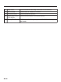
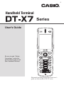
E Handheld Terminal Series User’s Guide Be sure to read “Safety Precautions” inside this guide before trying to use your Handheld Terminal. Illustrated operating instructions in this user’s guide use laser model of DT-X7 series. • This Product is equipped with the Brycen BL-RAPPORE Stack and My Wirefree Network Bluetooth User Interface Application, the use of which is governed by a license granted by Brycen Co., Ltd. • BLUETOOTH is a registered trademark owned by Bluetooth SIG, Inc. and licensed to CASIO COMPUTER CO., LTD. • Microsoft and Windows are either registered trademarks or trademarks of Microsoft Corporation in the United States and/or other countries. Information in this document is subject to change without advance notice. CASIO Computer Co., Ltd. makes no representations or warranties with respect to the contents or use of this manual and specifically disclaims any express or implied warranties of merchantability or fitness for any particular purpose. Contents Safety Precautions .........................................................................................E-3 Operating Precautions ...................................................................................E-8 Important ........................................................................................................E-9 Regulatory Information ...............................................................................E-10 Checking in the Box .....................................................................................E-14 Handheld Terminal System Configuration .................................................E-15 General Guide ...............................................................................................E-18 Loading and Removing the Battery Pack...................................................E-21 Loading .............................................................................................................. E-22 Removing ........................................................................................................... E-23 Attaching the Hand Strap ............................................................................E-25 Setting up ......................................................................................................E-26 Using the Mouse Emulator Function ................................................................. E-26 Adjusting Display Brightness ............................................................................ E-28 Display Auto Dimmer ........................................................................................ E-28 Using the Laser Scanner (DT-X7M10E/DT-X7M10R2) ...............................E-29 Attaching the Bumper ........................................................................................ E-29 Warning Label .................................................................................................... E-30 Bar Code Scanning Position .............................................................................. E-30 Adjusting the Laser Light Emission Width .................................................E-31 Using the C-MOS Imager (DT-X7M30E/DT-X7M30R) ................................E-33 Warning Label .................................................................................................... E-34 Using the Linear Imager (DT-X7M10U) .......................................................E-35 Warning Label .................................................................................................... E-35 Performing Communications .....................................................................E-36 IR Communication ............................................................................................. E-36 Bluetooth® Communication ............................................................................... E-37 Resetting the Handheld Terminal ................................................................E-38 Performing a Full Reset (Initialization) ............................................................ E-39 E-1 DT-X7 Specifications ...................................................................................E-40 Using the USB Cradle (HA-F60IO) ...............................................................E-44 General Guide .................................................................................................... E-44 Connecting the USB Cradle Power Supply .......................................................E-46 Specifications .....................................................................................................E-48 Using the Ethernet Cradle (HA-F62IO)........................................................E-49 General Guide .................................................................................................... E-49 Connecting the Ethernet Cradle Power Supply.................................................. E-51 Specifications .....................................................................................................E-53 Using the Cradle-type Battery Charger (HA-F30CHG) ..............................E-54 General Guide .................................................................................................... E-54 Connecting the AC Adaptor for Cradle-type Battery Charger ........................... E-55 Specifications .....................................................................................................E-57 Using the Cradle-type Dual Battery Charger (HA-F36DCHG) ..................E-58 General Guide .................................................................................................... E-58 Charging Battery Pack ....................................................................................... E-60 Connecting Multiple Cradle-type Dual Battery Chargers..................................E-61 Specifications .....................................................................................................E-62 Using the Dual Battery Charger (HA-F32DCHG)........................................E-64 General Guide .................................................................................................... E-64 Charging Battery Pack ....................................................................................... E-66 Connecting Multiple Dual Battery Chargers...................................................... E-67 Specifications .....................................................................................................E-68 Using Rechargeable Battery Pack ..............................................................E-69 Battery Pack Specifications................................................................................E-70 Large-capacity Battery Pack Specifications .......................................................E-70 Attaching the Hand Belt (HA-F95HB) ..........................................................E-71 Attaching the Hand Belt.....................................................................................E-71 E-2 Safety Precautions Congratulations upon your selection of this CASIO product. Be sure to read the following Safety Precautions before trying to use it for the first time. Your neglect or avoidance of the warning and caution statements in the subsequent pages causes the danger of fire, electric shock, malfunction and damage on the goods as well as personal injury. Markings and Symbols The following are the meanings of the markings and symbols used in these Safety Precautions. Danger This symbol indicates information that, if ignored or applied incorrectly, creates the danger of death or serious personal injury. Warning This symbol indicates information that, if ignored or applied incorrectly, creates the possibility of death or serious personal injury. Caution This symbol indicates information that, if ignored or applied incorrectly, creates the possibility of personal injury or property damage. • A diagonal line indicates something you should not do. The symbol shown here indicates you should not try to take the unit apart. • A black circle indicates something you should do. The symbol shown here indicates you should unplug the unit from the wall outlet. Warning Disassembly and Modification • Never try to disassemble or modify the Handheld Terminal and its options including battery pack and battery in any way. Abnormal Conditions • Should the Handheld Terminal and/or its options including battery pack and battery become hot or start to emit smoke or a strange odor, immediately turn off the power and contact your dealer or distributor whom you purchased the product from, or an authorized CASIO service provider. E-3 Warning Dust and Moisture • Though the Handheld Terminal is dust and water splash resistant, its options including the battery pack are not. Keep loose metal objects and containers filled with liquid away from your Handheld Terminal and the options. Also, never handle the Handheld Terminal and the options while your hands are wet. Laser Light • The products (Laser Scanner and C-MOS Imager models) scan bar codes using laser light. Never look directly into the laser light or shine the laser light into the eyes. LED Light • This product (DT-X7M10U) scans bar codes using LED light. Never look directly into the LED light or shine the LED light into the eyes. Warning Interference with the Operation of Other Equipment (Using Wireless Data Communication) 11 • Keep your Handheld Terminal at least 22 centimeters (8 /16") away from anyone wearing a pacemaker. Radio waves emitted by the Handheld Terminal can affect the operation of a pacemaker. • Before the use in aircraft, be sure to consult with cabin crew for interference the Handheld Terminal emits. • Before the use in medical facility, be sure to consult with the facility management or the manufacture of a specific medical equipment that the Handheld Terminal may interfere with. • Do not use the Handheld Terminal nearby gas pump or chemical tank or any other places flammable or explosive. E-4 Caution Foreign Objects • Take care to ensure that metals or combustible objects are not inserted into the openings of the Handheld Terminal or its options, and not to allow moisture to get inside of them. Location • Install the cradle properly on a flat and stable surface so that it cannot fall down onto floor. • Do not leave the Handheld Terminal and its options for a long period in a car parked in direct sunlight. LCD Screen • Never apply strong pressure to the screen or subject it to strong impact. Doing so can crack the LCD Screen. E-5 Optional Lithium-ion Battery Pack Danger • Never use the Handheld Terminal and its option including the battery pack and battery next to open flame, near a stove, or any other area exposed to high heat, or leave them for a long period of time in a vehicle parked in direct sunlight. • Never use the battery pack with any device other than the Handheld Terminal. • Never dispose of the battery pack by incinerating it or otherwise expose it to heat. • Never transport or store the battery pack together with metal objects that may result in shorting positive (+) and negative (–) terminals of the battery pack. Be sure to place the battery pack in its case whenever transporting or storing it. • Never throw the battery pack or otherwise subject it to strong impact. • Never pierce the battery pack with nails, hit it with a hammer, or step on it. • Use only the specified battery charger to charge the battery pack. Warning • Never place the battery pack in a microwave oven or any other high-voltage device. • If the amount of time period the battery pack can serve becomes considerably short even after it has been fully charged for the specified time period, stop using it. • Should the battery pack start to leak or emit a strange odor, immediately move it away from any flame nearby. Leaking battery fluid is combustible. • Should fluid from the battery pack accidentally get into your eyes or on the skin, do not rub it. Immediately rinse it off with clean tap water and then consult a physician. Caution • Replace only with the same type of battery pack recommended by CASIO. Dispose of used battery packs according to the local regulation. • Keep the battery pack out of the reach of small children. E-6 Power Supply / AC Adaptor Warning • Do not use the Handheld Terminal at a voltage other than the specified voltage. Also, do not connect the Handheld Terminal to a multi-plug power strip. • Never modify, sharply bend, twist, or pull on the power cord. • Never use a detergent to clean AC adaptor and its power cable, especially on the plug and the jack. • When using the battery chargers and the cradles, be sure to use the respective AC adaptors. Caution • Never pull on the power cord when unplugging it. Always hold the plug when unplugging it from the wall outlet. • Never touch the plug while your hands are wet. • Be sure to unplug the power cord from the wall outlet before cleaning the battery chargers and the cradles. • Unplug the power cord from the wall outlet whenever leaving the battery chargers and the cradles unattended for a long period. • The housing of the AC adaptor can become warm during normal use. • At least once a year, unplug the AC adaptor from the wall outlet and clean any dust that builds up between the prongs of the plug. Dust built up between the prongs can lead to the danger of fire. Backup Copies of All Important Data Caution • Note that CASIO Computer Co., Ltd. shall not be held liable to you or any third party for any damages or loss caused by deletion or corruption of data due to use of the Handheld Terminal, malfunction or repair of the Handheld Terminal or its peripherals, or due to the batteries going dead. • The Handheld Terminal employs electronic memory to store data, which means that memory contents can be corrupted or deleted if power is interrupted due to the batteries going dead or incorrect battery replacement procedures. Data cannot be recovered once it is lost or corrupted. Be sure to make backup copies of all important data. One way to do this is to use the separately sold cradles to transfer data to a computer. E-7 Operating Precautions Your Handheld Terminal and its options are precision. Improper operation or rough handling can cause problems with data storage and other problems. Note and observe the following precautions to ensure proper operation. • Do not continue operating the Handheld Terminal when battery power is low. Doing so can cause data to be lost. When the battery goes low, charge it as soon as possible. • Do not leave dead battery pack in the Handheld Terminal for a long period. Dead battery pack can leak, leading to malfunction and damage to the Handheld Terminal. • Use the Handheld Terminal and its options only within the specified temperature range. Use outside of the specified temperature range creates the risk of malfunction. • Avoid using the Handheld Terminal and its options in areas subject to the following conditions. — Large amounts of static electricity — Extreme heat or extreme cold — High humidity — Sudden temperature extremes — Large amounts of dust • Never use thinner, benzene, cosmetic cleaning fluids, or other volatile agents to clean the Handheld Terminal. To clean the Handheld Terminal, wipe it with a dry cloth, or a cloth moistened in a weak solution of water and a mild neutral detergent. Wring all excess moisture from the cloth before wiping. • Although the Handheld Terminal meets the IP54 level of the International Standard IEC60529, pay your attention to the following when using it in the rain. — After a large amount of rain or water falls on the Handheld Terminal, wipe off it immediately. — Do not use it in the rain for a long period of time. — Make sure the battery cover and connect cover are closed securely before using it. — Do not press on the screen or keys with excessive force when using it in the rain. • Dead Pixels The LCD panel employed in this product uses high precision and substantial number of components which commonly cause a small number of the pixels not to light or to remain lit all the time. This is due to the characteristics of LCD panel yield in accuracy over 99.99% and permissible. E-8 Important • This guide does not include any information about programming and download procedures. See the applicable separate documentation for information about the procedures. After Service • Should this product ever malfunction, contact your original retailer providing information about the product name, the date you purchased it, and details about the problem. This mark applies to EU countries and Turkey only. E-9 Regulatory Information The USA and Canada GUIDELINES LAID DOWN BY FCC RULES FOR USE OF THIS UNIT IN THE U.S.A. (not applicable to other areas). NOTICE This equipment has been tested and found to comply with the limits for a Class B digital device, pursuant to Part 15 of the FCC Rules. These limits are designed to provide reasonable protection against harmful interference in a residential installation. This equipment generates, uses and can radiate radio frequency energy and, if not installed and used in accordance with the instructions, may cause harmful interference to radio communications. However, there is no guarantee that interference will not occur in a particular installation. If this equipment does cause harmful interference to radio or television reception, which can be determined by turning the equipment off and on, the user is encouraged to try to correct the interference by one or more of the following measures: • Reorient or relocate the receiving antenna. • Increase the separation between the equipment and receiver. • Connect the equipment into an outlet on a circuit different from that to which the receiver is connected. • Consult the dealer or an experienced radio/TV technician for help. FCC WARNING Changes or modifications not expressly approved by the party responsible for compliance could void the user’s authority to operate the equipment. Proper connectors must be used for connection to host computer and/or peripherals in order to meet FCC emission limits. Caution Exposure to radio frequency radiation (below is for portable device) To comply with FCC RF exposure compliance requirements, this device must not be co-located or operating in conjunction with any other antenna or transmitter. Declaration of Conformity Model Number: HA-F60IO, HA-F62IO Trade Name: CASIO Responsible party: Casio America, Inc. Industrial Handheld Division Address: 10710 Baxter Avenue, Los Altos, California 94024 USA Telephone number: 585-624-2562 This device complies with Part 15 of the FCC Rules. Operation is subject to the following two conditions: (1) This device may not cause harmful interference, and (2) this device must accept any interference received, including interference that may cause undesired operation. For Customers in Canada These Class B digital apparatuses comply with Canadian ICES-003. Cet appareil numériqué de la classes B est conformé à la norme NMB-003 du Canada. These devices comply with RSS 210 of Industry Canada (IC). Operation is subject to the following two conditions: (1) These devices may not cause interference, and (2) These devices must accept any interference, including interference that may cause undesired operation of this device. E-10 L’utilisation de ce dispositif est autorisée seulement aux conditions suivantes : (1) il ne doit pas produire de brouillage et (2) l’utilisateur du dispositif doit être prêt à accepter tout brouillage radioélectrique reçu, même si ce brouillage est susceptible de compromettre le fonctionnement du dispositif. Exposure to radio frequency radiation The installer of this radio equipment must ensure that the antenna is located or pointed such that it does not emit RF field in excess of Health Canada limits for the general population; consult Safety Code 6, obtainable from Health Canada's website at www.hc-sc.gc.ca/rpb. Europe We, the undersigned. Company Address, City Country Phone number Fax number CASIO Europe GmbH Casio-Platz 1, 22848 Norderstedt Germany +49(0)40-528-65-0 +49(0)40-528-65-424 certify and declare under our sole responsibility that the following equipments: Product description/Intended use EU/EFTA member states intended for use Member states with restrictive use Manufacturer Brand Type EU: Austria, Belgium, Bulgaria, Cyprus, Czech Republic, Denmark, Estonia, Finland, France, Germany, Greece, Hungary, Ireland, Italy, Latvia, Lithuania, Luxembourg, Malta, Netherlands, Poland, Portugal, Romania, Slovakia, Slovenia, Spain, Sweden, United Kingdom EFTA: Switzerland, Iceland, Lichtenstein, Norway NONE CASIO COMPUTER CO., LTD. CASIO DT-X7M10E, DT-X7M10R2, DT-X7M30E, DTX7M30R are tested and found to conform with the essential requirements for protection of health and the safety of the user and any other persons and Electromagnetic Compatibility, as included in following standards: Standard EN 60950-1 EN 301 489-17 EN 50371 (for DT-X7M10R2, DTX7M30R) lssue date 2001 v1.2.1: 2002.08 2002 and are tested and found to conform with the essential radio test suites so that they effectively use the frequency spectrum allocated to terrestrial/space radio communication and orbital resources so to as to avoid harmful interference, as included in following standards: E-11 Standard EN 300 328 EN 50371 (for DT-X7M10R2, DTX7M30R) lssue date v1.7.1: 2006.10 2002 and therefore comply with the essential requirements and provisions of the Directive 1999/5/EC of the European Parliament and of the council of March 9, 1999 on Radio equipment and Telecommunications Terminal Equipment and the mutual recognition of their conformity and with the provisions of Annex III (Conformity Assessment procedure referred to in article 10). The technical documentation as required by the Conformity Assessment procedure is kept at the following address: Company Address, City Country Phone number Fax number CASIO Europe GmbH Casio-Platz 1, 22848 Norderstedt Germany +49(0)40-528-65-0 +49(0)40-528-65-424 0984 Products are for distribution within all member states of the EU. France limited to 2446.5-2483.5 Mhz Indoor use. Belgium limited to 2400-2483.5 Mhz Indoor, 2460-2483.5 Mhz Outdoor use. The information described above dates from January 2003 and may be subjected to future changes. Manufacturer: CASIO COMPUTER CO., LTD. 6-2, Hon-machi 1-chome, Shibuya-ku, Tokyo 151-8543, Japan Representative within the European Union: CASIO EUROPE GmbH Casio-Platz 1, 22848 Norderstedt, Germany E-12 The CASIO DT-X7M10E, DT-X7M10R2, DT-X7M30E, DT-X7M30R and DT-X7M10U models are designed, tested and found to meet the relevant regulatory standards described below. DT-X7M10E, DT-X7M10R2, DT-X7M30E, DT-X7M30R International standards: IEC 60825-1 IEC 60529, IP54 level Europe standards: EN 60950-1 EN 60825-1 EN 300 328 EN 301 489-17 China standards: GB 4943 GB 9254 GB 17625.1 GB 7247.1-2001 [2002] 353 Taiwan standards: CNS 14336 CNS 13438 LP 0002 Australia and New Zealand standards: AS/NZS CISPR22 DT-X7M10U International standards: IEC 60529, IP54 level IEC 60825-1 USA standards: FCC Part 15B FCC Part 15C UL 60950-1 Canada standards: RSS-GEN, RSS-210 ICES-003 cUL 60950-1 The DT-X7M10R2-CN and DT-X7M30R-CN for the destination of China only are designed and built to meet the Chinese radio related regulations. These models do not permanently integrate a microphone described in this guide which disables the capability of voice data transmission via Internet Protocol including the "VOIP". The description about the microphone is thus intended for other models which are not available in China. E-13 Checking in the Box Please check the contents of the box before using the Handheld Terminal for the first time. Open the box and make sure that all the items shown here are included. Handheld Terminal Large-capacity Battery Pack Cover Bumper* Hand Strap * This is attached to the main body of C-MOS Imager models. User's Guide (this manual) E-14 Handheld Terminal System Configuration Options USB Cradle HA-F60IO DT-X7 Series Ethernet Cradle HA-F62IO Cradle-type Battery Charger HA-F30CHG The illustration shows the USB Cradle (HA-F60IO). Cradle-type Dual Battery Charger HA-F36DCHG E-15 Options Battery Pack HA-F20BAT (Battery Pack) HA-F21LBAT (Large-capacity Battery Pack) Dual Battery Charger HA-F32DCHG AC Adaptor for USB Cradle/Ethernet Cradle/ Dual Battery Charger AD-S42120B AD-S42120B-N AC Adaptor for Cradle-type Battery Charger AD-S15050BE E-16 AD-S15050B-N Options AC Adaptor for Cradle-type Dual Battery Charger AD-S60160BE AD-S60160BU AD-S60160B-N Cable DT-380USB Power Cord for Europe Power Cord for North America Power Cord for Taiwan Power Cord for Korea Power Cord for Australia AC-CORD-EU AC-CORD-US AC-CORD-TW AC-CORD-KR AC-CORD-AU Hand Belt HA-F95HB E-17 General Guide TOP 17 17 DT-X7M10E DT-X7M10R2 DT-X7M30E DT-X7M30R Left 17 DT-X7M10U Front 12 3 Right Back 4 16 16 23 22 5 14 15 24 7 24 7 6 8 11 25 9 10 12 13 21 20 21 Bottom 18 19 19 1 Indicator 1 Orange: Charging the battery pack. Green: Charging the battery pack is complete. Red: Battery pack error or the surrounding temperature is out of the charging temperature range. 2 Indicator 2 Flashes in blue when operating via Bluetooth or in orange when operating via WLAN. Lights in green when reading a bar code successfully. 3 Speaker Buzzer and voice messages are output here. 4 Power Key Turns the power on and off. 5 Screen Displays text and operating instructions. 6 Trigger Center Key Used to perform bar code reading. Can be assigned an arbitrary function. E-18 7 Cursor Keys Perform the same functions as the up and down arrow keys on a PC keyboard. 8 Enter Key Press when finishing entering numerical values or when moving to the next step. 9 Numeric Keys Used to enter numeric values and decimal points. 10 Fn Key Used to make various settings in combination with the function keys or numeric keys or when starting a pre-registered application. 11 CLR Key Used to clear one letter to the left of the cursor. 12 Function Keys Various functions other than bar code reading can be assigned to these keys. The default key assignments are as follows. F1: Similar function as the Alt key on a PC keyboard. F2: Similar function as the Shift+Tab keys combination on a PC keyboard. Used to move the cursor among entry or selection items. F3: Similar function as the Tab key on a PC keyboard. Used to move the cursor among entry or selection items. F4: Not assigned. F5: Enter a space. F6: Similar function as the cursor left key on a PC keyboard. F7: Similar function as the cursor right key on a PC keyboard. F8: Select text entry mode. (The mode changes in order of Numeric ➝ Uppercase letter ➝ Lowercase letter) 13 Microphone Used to input a sound including voice. 14 Trigger R Key Used to perform bar code reading. 15 Trigger L Key Used to perform bar code reading. 16 Contact Scanning Guide Attachment Holes Used to mount the contact scanning guide. (DT-X7M10E/DT-X7M10R2) 17 Barcode Reader Port Laser light or LED light is emitted from this window that reads bar codes. 18 IR Port Used for communication with another Handheld Terminal. 19 Power Contacts Used to receive power provided by the USB Cradle or Ethernet Cradle. 20 Data Communication Used for data communications. Terminal E-19 21 Strap Holes Used to attach the hand strap. Also used for the hand belt. 22 Reset Switch Used to reset the Handheld Terminal. 23 Hand Belt Holes Used to attach the hand belt. 24 Battery Pack Cover Lock Switch Used to lock the battery cover and to release. 25 Battery Pack Cover Used to cover the battery compartment that holds the battery pack inside. E-20 Loading and Removing the Battery Pack Your Handheld Terminal uses two types of battery: a battery pack and a memory backup battery. The battery pack is used to power normal operations and to store data, while the memory backup battery provides the power required to maintain memory contents when the battery pack power is unable to supply power for some reason. The operating power is supplied by a battery pack. You can choose between a battery pack (HA-F20BAT) and a large-capacity battery pack (HA-F21LBAT). The backup battery is installed inside of the Handheld Terminal. This guide uses the following terms to refer to the batteries. Battery Pack: Rechargeable battery pack (HA-F20BAT or HA-F21LBAT) for normal operations and data storage Backup Battery: Built-in battery for memory backup When the battery pack power goes low, immediately charge it or replace it with a charged battery pack. You can use the Dual Battery Charger, the Cradle-type Battery Charger, the Cradle-type Dual Battery Charger, the USB Cradle, or Ethernet Cradle to charge a battery pack. See the sections of this guide that cover the Dual Battery Charger, the Cradle-type Battery Charger, the Cradle-type Dual Battery Charger, the USB Cradle, and the Ethernet Cradle for information about how to use them for charging. Important! Always keep backup copies of all important data! • The battery pack powers normal operation and also provides power required to maintain memory contents, while the backup battery provides backup power to maintain memory contents. Because of this, you should not remove the battery pack if the backup battery is dead. Removing the battery pack while the backup battery is dead causes data in the memory to be corrupted or lost. Note that once data is lost it cannot be recovered. Always keep separate backup copies of all important data. • The charge of a battery pack when you purchase it may be depleted due to testing at the factory or natural discharge during shipment and storage. Be sure to charge the battery pack before you use it. • The life of a battery pack is limited, and charging a battery pack causes it to gradually lose its ability to maintain the charge. If your battery pack seems to require charging very frequently, it probably means it is time to purchase a new one. • If a battery pack is used past the end of its service life, it may swell up in size. In such a case, replace the battery pack with a new one. • When the battery pack is attached, it takes 30 minutes for the backup battery to obtain enough charge for maintaining memory (RAM) contents for 10 minutes. It takes two days for the backup battery to achieve a full charge. E-21 Loading 1. Turn over the Handheld Terminal. 2. Remove the rechargeable battery pack cover as follows: Slide the left and right lock switches for the rechargeable battery pack cover simultaneously in the direction indicated by the arrows. While holding the switches back, hook your fingertips into the notches in the rechargeable battery pack cover and lift the cover up in the direction indicated by the arrow. Notch Notch 3. Load a battery pack (HA-F20BAT) or large-capacity battery pack (HA-F21LBAT). Take care that the battery pack is oriented correctly when you load it. In addition, load the battery back while making sure that the end of the battery pack removal tape is protruding above the battery pack. 4. Put back the battery pack cover in the compartment as instructed by the arrows, and in the illustration. E-22 After putting back the cover, firmly press the cover so that it is locked in the position by the two Battery Pack Cover Lock Switches. • Ensure that both the switches returned all the way down to the home positions as indicated by the two arrows. If the switches are lackadaisically positioned, it causes the switches not to activate. When loading a large-capacity battery pack, use the large-capacity battery cover instead of the standard battery cover. Battery Pack Cover Lock Switches Removing 1. Make sure that the Handheld Terminal is turned off. If the power is on, press the power key to turn it off. 2. Turn over the Handheld Terminal. 3. Remove the rechargeable battery pack cover as follows: Slide the left and right lock switches for the rechargeable battery pack cover simultaneously in the direction indicated by the arrows. While holding the switches back, hook your fingertips into the notches in the rechargeable battery pack cover and lift the cover up in the direction indicated by the arrow. E-23 4. Remove the battery pack by pulling up the removal tape as shown in the illustration. Loading the large-capacity battery pack into the Handheld Terminal After loading the large-capacity battery pack, you need to use the special large-capacity battery pack cover in place of the standard battery pack cover. “Loading and Removing” of the large-capacity battery pack cover is the same as those for the standard battery pack cover. Important! • When removing the battery pack, make sure you do not leave the Handheld Terminal without a battery pack for more than about 10 minutes. Doing so can cause data in the memory to be deleted. • Never try to use other type of battery than the ones that are specified for this product. • When removing the battery pack, pull the removal tape straight up and remove the battery pack. Removing with excessive force can damage the battery pack. • Before starting to use the DT-X7, ensure that the battery pack cover is properly closed. If not, the power cannot be turned on or is turned off abruptly while the DT-X7 is in use. E-24 Attaching the Hand Strap The hand strap can be used to prevent the Handheld Terminal from dropping when carrying it around. Since there are two strap holes where the hand strap can be attached, use the hole that affords the ease of use. Attach the hand strap according to the procedure described below. To attach the hand strap 1. Pass the thin cord of the hand strap through the hand strap hole on the back of the Handheld Terminal. 2. Pass the other end of the strap (the part you put around your hand) through the loop formed by the thin cord. Important! Do not swing the Handheld Terminal around holding the hand strap. E-25 Setting up Using the Mouse Emulator Function The mouse emulator function lets you make settings and adjustments by using a mouse cursor. To use the mouse cursor, first set up the mouse emulation mode by following the below procedure. In the emulation mode, the numeric keys and Trigger R key are used to manipulate the mouse cursor. (In the emulation mode, the numeric keys and Trigger R key cannot be used for entering numerics and scanning bar codes respectively.) ■ Activating the mouse emulator function • While no mouse cursor is shown on the screen, press the “Fn” key followed by the “4” key. The mouse cursor appears, and the mouse emulator function is now active. * To turn off the function, press the same key sequence again, i.e. “Fn” key ➝ “4” key. * Each push of this key toggles the function between on and off. ■ Using the mouse cursor Activate the mouse emulator function as described above. Mouse cursor movement • Press a numeric key for the direction in which you want to move the mouse cursor. Mouse cursor moves in the arrow direction. * Holding down a key moves the mouse cursor continuously. Left click This serves for selecting a file, making a menu selection, or a similar action. • Move the mouse cursor to the position where you want to click, and press the “5” key. E-26 Right click (calling up a menu) • Move the mouse cursor to the position where you want to click, and press the Trigger R key. Left double click Performing this action while the mouse cursor is on an icon starts an application, opens a file, etc. • Move the mouse cursor to the position where you want to double click, and press the “5” key twice. * The double click timing follows the double tap setting of Windows CE. The setting can be changed by accessing the “Mouse” icon in the Control Panel. Dragging This action allows you to move an application icon on the screen or a file or folder in File Explorer. • Move the mouse cursor to the position where you want to start dragging, and press the “5” key. Then move the mouse cursor by holding down the “5” key and pressing another numeric key for the direction in which you want to move. The selected item will be dragged along with the cursor. When you release the “5” key, the item is dropped at the current location. E-27 Adjusting Display Brightness You can use the following procedure to adjust display brightness to make it easier to read under different lighting conditions. • Press the “Fn” key and then press the “5” key or “6” key after confirming that “F” is displayed in the lower right corner of the screen. Pressing the “5” key adjusts brightness for a darker display, while pressing the “6” key adjusts brightness for a lighter display. * In order to continue to make adjustments, press the “5” key or “6” key after pressing the “Fn” key. Display Auto Dimmer The display auto dimmer automatically lowers display brightness if you do not perform any operation for a specific period of time. This helps the battery power to be conserved. You can use the following procedure to specify a period of time that should be allowed to elapse until when the auto dimming is initiated. 1. Use the “ ”/“ ” keys to move the focus to the [Start] icon and press the Enter key. Then navigate to Settings ➝ Control Panel with the Enter key to bring up the Control Panel. Focus 2. Move the focus to the “Brightness” icon and press the Enter key. Then use the “ ”/“ ” keys to move the focus to the tabs and use the “<”/ “>” keys to select the [Backlight] tab. Adjust the displayed items. * The mouse emulator function can also be used to make the adjustment. E-28 Using the Laser Scanner (DT-X7M10E/DT-X7M10R2) 1. After turning on the power, position the laser scanner close to a bar code and then press the trigger key. 2. The laser emits light and scans the bar code. If scanning is completed normally, Indicator 2 displays a green light and a buzzer sounds. Important! • If you are unable to scan a bar code, try changing the angle at which the scanner is held or distance from the scanner to the bar code, and then try scanning again. • This Handheld Terminal is capable of scanning bar codes at a distance of about 40-400 mm (19/16"-153/4"). Furthermore, the distance at which scanning is possible may vary according to the bar code symbology. Attaching the Bumper 1. Attach the Bumper on DT-X7. 2. Be sure that the Bumper and the new battery pack cover are attached on DT-X7 as shown in the illustrations. . E-29 Warning Label • This label is a warning and caution label for Class 2 laser products that comply with IEC60825-1:1993+A1:1997+A2:2001. • Although Class 2 laser light is only emitted momentarily, never look directly into the beam light. • The laser light emitted by this laser scanner has a maximum output of less than 1 mW and a wavelength of 650 nm. • Use of controls or adjustments or performance of procedures other than those specified herein may result in hazardous radiation exposure. Bar Code Scanning Position Position the laser scanner close to the bar code when scanning small bar codes. Position the laser scanner at a distance from the bar code so that the bars enter the light when scanning large bar codes. Margin Good Bad Margin Good Bad Good Bad Bad Warning! ■ Never look directly into the laser light. E-30 • The products with the integrated Laser Scanner module scan bar codes using laser light. Never look directly into the laser light or shine the laser light into the eyes. Adjusting the Laser Light Emission Width The emission width of the laser light emitted by the Handheld Terminal can be adjusted. Adjust the emission width when it has been changed. * The mouse emulator function can also be used to make the adjustment. 1. Use the “ ”/“ ” keys to move the focus to the [Start] icon and press the Enter key. Then navigate to Settings ➝ Control Panel with the Enter key to bring up the Control Panel. 2. Move the focus to the [Scanner Setting] icon and press the Enter key. The display appears as shown at right. 3. Use the “ ”/“ ” keys to move the focus to the tabs and use the “<”/“>” keys to select the [Others] tab. E-31 4. Use the “ ”/“ ” keys to move the focus to [Calibration] and press the Enter key. The message appears as shown at right. 5. Press the Trigger Key to emit laser light, and align the light with the barcode for adjusting emission width. • Align the laser light with the narrow bars on both sides. • The message appears as shown at right when adjustment is completed. • Repeat the setting if “Setting failed” message appears. Emission Width Adjustment Bar Code E-32 Using the C-MOS Imager (DT-X7M30E/DT-X7M30R) 1. Turn on the Handheld Terminal, position its C-MOS Imager reader port near the bar code or 2D code, and then press the Trigger Key. 2. The Handheld Terminal reads the code by emitting laser and red lights. Indicator 2 (read operation indicator lamp) lights in green when the reading is successful. Bar code and stacked 2D code Reading Guide When you press the Trigger key, LEDs in the Handheld Terminal emit laser and red lights. Align the laser frame with the center of the bar code or 2D code you are trying to read. Take particular care aligning the light when there are other bar codes nearby. When reading a bar code in large size, adjust the position of the Handheld Terminal so that the entire code is enclosed within the laser frame. For small size, move the Handheld Terminal closer to it. Important! • If you have problem not properly reading a code, change the angle and/or the distance between the code and the Handheld Terminal and try reading it again. • A bar code can be read from a distance of 40mm to 410mm (19/16" to 161/8"), and a stacked 2D code can be read from a distance of 50mm to 250mm (115/16" to 913/16") and matrix 2D code can be read from a distance of 60mm to 150mm (23/8" to 515/16"). The actual reading distance depends on the symbology and the resolution. • Note that a special reader application is required to read bar codes and 2D codes. • Fingerprints, dust, dirt, or stain on the C-MOS Imager reader port can cause abnormal reading. Should the reader port become dirty, wipe it clean with a soft and dry cloth. E-33 Warning Label DT-X7M30E DT-X7M30R DT-X7M30R-CN • This label is a warning and caution label for Class 2 laser products that comply with IEC60825-1:1993+A1:1997+A2:2001. • Although Class 2 laser light is only emitted momentarily, never look directly into the beam light. • The laser light emitted by this laser scanner has a maximum output of less than 1 mW and a wavelength of 650 nm. • Use of controls or adjustments or performance of procedures other than those specified herein may result in hazardous radiation exposure. Warning! Never look directly into the laser light. • The products with the integrated C-MOS Imager module scan bar codes using laser light. Never look directly into the laser light or shine the laser light into the eyes. E-34 Using the Linear Imager (DT-X7M10U) 1. After turning on the power, position the reader port close to a bar code and then press the Trigger key. 2. The LED emits light and scans the bar code. When scanning is completed normally, Indicator 2 displays a green light and a buzzer sounds. Important! • If you are unable to scan a bar code, try changing the angle at which the Handheld Terminal is held or distance between the reader port and the bar code, and then try scanning again. • This Handheld Terminal is capable of scanning bar codes at a distance of about 60-300 mm (26/16"-1113/16"). Furthermore, the distance at which scanning is possible may vary according to the bar code symbology. Warning Label Warning! ■ Never look directly into the LED light. • This product scans using LED light. Never look directly into the LED light or shine the LED light into the eyes. About the Class 1 LED Label • This label identifies the Handheld Terminal as a Class 1 LED product compliant with IEC60825-1 (ed.1.2). E-35 Performing Communications IR Communication IR communication can be used to transmit data between two Handheld Terminals. When performing IR communication, orient the IR ports of both Handheld Terminals so they are pointing directly at each other. The ports can be in direct contact with each other, or they can be separated by up to 30cm (1113⁄16") (up to 20cm (7 7⁄8") for communication between units). Important! • A high-sensitivity communication element is used during IR communication. • In order to ensure successful communication, avoid using cellular phones or other devices that emit radio wave in the area where you are performing IR communication. • If you need to use such a device, move away from the communicating Handheld Terminals. In case of a cellular phone, keep it at least 30cm (1113⁄16") away. E-36 Bluetooth® Communication Bluetooth® interface can also be used to transmit data between two Handheld Terminals. With Bluetooth® the two Handheld Terminals should be located within about three meters (9'103⁄8") (Laser Scanning and C-MOS Imager models) or 100 meters (328'1") (DTX7M10U) from each other, as long as there is nothing blocking the path between them. Important! Observe the following precautions to help ensure that Bluetooth communication is successful. • Make sure there is at least two meters (6'7") between the Handheld Terminal and other equipment (electrical appliances, audio-visual equipment, OA equipment, and digital cordless telephones, facsimile machines, etc.). (Take special care with microwave ovens. Allow at least three meters (9'103⁄8) between the Handheld Terminals in wireless operation and a microwave oven.) When approaching such a device when its power is turned on, proper communication may prove impossible while this may also cause interference with TV and radio reception (images produced by certain UHF and broadcast satellite channels may become blurry). • Normal communication may not be possible in an area near a broadcast transmitter or wireless transmitter. If this happens, move the Handheld Terminal to a different location. Normal communication may not be possible in areas exposed to strong radio waves. • RF Wireless LAN Interference Because Bluetooth® and RF wireless LAN use the same frequency band (2.4GHz), radio interference can occur if there is a wireless LAN device nearby. This can result in lower communication speeds, or even make it impossible to establish a connection. If this happens, try the following countermeasures. • Move at least 10 meters (32'103⁄4") away from the wireless LAN device. • If you cannot keep the distance at least 10 meters (32'103⁄4") or more between the Handheld Terminal and a wireless LAN device, turn off the power of either the Handheld Terminal or the wireless LAN device. ® • Although the Handheld Terminal enables wireless LAN and Bluetooth communication to be used simultaneously as a result of being equipped with Bluetooth® Ver.2.0, communication may not be possible depending on the surrounding radio wave environment. E-37 Resetting the Handheld Terminal Resetting the Handheld Terminal is the same as restarting a PC. Performing a reset causes all unsaved inputs and edits to be lost, but data that is already stored in the memory as well as all settings should be unaffected. Use reset to restore normal operation whenever the Handheld Terminal operates abnormally due to misoperation or some other reason. Use a stylus to press the reset switch on the back of the DT-X7. This starts the reset operation. * Do not use a toothpick or pencil or other object whose tip may break off when pressing the reset switch. Otherwise there is a risk of damage. If reset does not find a memory problem The Handheld Terminal restarts, and normal operation is restored. If reset finds a memory problem A message like the one shown below appears on the display when the reset operation discovers a memory problem. Trigger R Key When this message appears, press the Trigger key to continue with the reset operation. Note, however, that reset may not be successful depending on the condition of the memory. In this case, perform the full reset operation described on the next page. E-38 Performing a Full Reset (Initialization) Performing a full reset initializes memory. This means that all data stored in the memory (RAM) is deleted and all the settings are returned to their initial factory settings. Perform a full reset whenever any one of the following conditions exists. • When you want to delete all memory contents and return the settings to their initial factory settings. • When you are no longer able to use the Handheld Terminal because you forgot your password. • When the Handheld Terminal does not operate normally due to a memory problem. • When the message “A problem with memory contents has been found. ...” appears. To perform a full reset Important! Performing a full reset deletes all data currently stored in the memory (RAM). If possible, backup data of the Handheld Terminal to a PC, Flash Memory, a memory card, or some other medium before performing a full reset. 1. While holding down the Power key and CLR key simultaneously, press the reset swicth using stylus for approximately one second and then release the reset switch first. The message shown below appears. • To cancel the full reset operation, press the Trigger L key. Trigger R Key 2. Press the Trigger R key. This causes the message shown below to appear. • To cancel the full reset operation, press the Trigger L key. Trigger R Key 3. Press the Trigger R key again. • Full reset is performed, all data in the memory (RAM) are erased and the start-up screen is displayed. E-39 DT-X7 Specifications Model: DT-X7M10E, DT-X7M10R2, DT-X7M10U, DT-X7M30E, DT-X7M30R CPU: Marvell® PXA270 416MHz Memory: 64MB RAM, 64MB Flash ROM (user area: approx. 28MB) OS: Microsoft® Windows® CE5.0 operating system, English Version Display: 2.4-inch, 320 × 240-dot transflective TFT color LCD Laser Scanner (DT-X7M10E, DT-X7M10R2): Readable symbologies: UPC-A, UPC-E, EAN8 (JAN8), EAN13 (JAN13), Codabar (NW-7), Code39, Interleaved 2 of 5 (ITF), MSI, Industrial 2 of 5, Code93, Code128 (EAN128), IATA, RSS-14, RSS Limited, RSS Expanded, RSS-14 Stacked, RSS Expanded Stacked* * RSS was renamed as GS1 DataBar in February 2007. Scanning distance: Within approximately 40-400 mm (19/16"-153/4") Linear Imager (DT-X7M10U): Readable symbologies: UPC-A, UPC-E, EAN8 (JAN8), EAN13 (JAN13), Codabar (NW-7), Code39, Interleaved 2 of 5 (ITF), MSI, Industrial 2 of 5, Code93, Code128 (EAN128), IATA, RSS-14, RSS Limited, RSS Expanded, RSS-14 Stacked, RSS Expanded Stacked * RSS was renamed as GS1 DataBar in February 2007. Scanning distance: Within approximately 60-300 mm (26/16"-1113/16") C-MOS Imager (DT-X7M30E, DT-X7M30R): Readable symbologies: 1D: UPC-A/UPC-E/EAN8 (JAN8)/EAN13 (JAN13)/Codabar (NW-7)/Code39/Interleaved 2 of 5 (ITF)/MSI/Code93/ Code128 (EAN128 (GS1-128))/Code11/IATA/RSS-14 (GS1 DataBar Omnidirectional)/RSS Limited (GS1 DataBar Limited)/ RSS Expanded (GS1 DataBar Expanded) Stacked 2D: PDF417/Micro PDF/CODE49/Composite/ Codablock F/TLC39/RSS Expanded Stacked (GS1 DataBar Expanded Stacked)/RSS-14 Stacked (GS1 DataBar Stacked) Matrix 2D: Aztec/DataMatrix/Maxicode/QR Code Scanning distance: 1D: 40 – 410 mm (19/16"-161/8") Stacked 2D: 50 – 250 mm (1911/16"-913/16") Matrix 2D: 60 – 150 mm (23/8"-57/8") IR Port: Interface: IrDA Ver. 1.3 LowPower Synchronization: Asynchronous, frame synchronization Transmission rate: Up to 4Mbps (max.) Bluetooth® (Laser Scanner and C-MOS Imager models): Protocol: Bluetooth® Specification Ver.2.0 Range: Approximately 3 m (9'103/8") (depends on radio wave conditions and environment) Output: 4dBm max. (PowerClass2) Bluetooth® (DT-X7M10U): Protocol: Bluetooth® Specification Ver.2.0 Range: Approximately 100 m (328'1") (depends on radio wave conditions and environment) Output: 12dBm max. (PowerClass1) E-40 WLAN(DT-X7M10R2, DT-X7M30R): Standards: Complies with IEEE 802.11b/g Diffusion Modulation: DS: 802.11b DS/OFDM: 802.11g Frequency: 802.11b/g: 2.400-2.4835 GHz Transmission Rate: 802.11b: Max. 11 Mbps 802.11g: Max. 54 Mbps Communication Range: 50 m indoors, 150 m outdoors (varies according to usage environment and transmission rate) Power Requirements: Power Source: HA-F20BAT Battery Pack HA-F21LBAT Large-capacity Battery Pack Memory Backup: Rechargeable Lithium Battery (Built-in) Consumption Current: DC 1.3A (DT-X7M10E) DC 1.6A (DT-X7M10R2) DC 1.4A (DT-X7M10U, DT-X7M30E) DC 1.7A (DT-X7M30R) Battery Life: Battery pack: DT-X7M10E/DT-X7M10U/DT-X7M30E Approximately 15 hours (HA-F20BAT)* Approximately 26 hours (HA-F21LBAT)* DT-X7M10R2/DT-X7M30R Approximately 15 hours (HA-F20BAT)* Approximately 26 hours (HA-F21LBAT)* Approximately 10 hours (HA-F20BAT)** Approximately 17 hours (HA-F21LBAT)** * under the conditions that CPU speed is set to the auto power save mode, backlight is set to off, and the ratio of cyclic operation of “Standby, Key input, and Scanning” is set at 20:1:1. ** under the conditions that CPU speed is set to the auto power save mode, backlight is set to off, and the ratio of cyclic operation of “Standby, Key input, Scanning, and WLAN” is set at 20:1:1:1. Memory backup: 10 minutes for protection of data in memory 3 days for backup of built-in clock Operating Temperature: –10°C to 50°C (14°F to 122°F) Operating Humidity: 10% to 80% RH (non-condensation) Dust and Water Splash Proof: IEC60529 standard, IP54 level Dimensions: Refer to “Dimensional Drawing” on the next page. Weight: DT-X7M10E, DT-X7M10R2: Approximately 145g (5.1oz) (when standard battery pack is installed) DT-X7M10U: Approximotely 155g (5.5oz) (when standard battery pack is installed) DT-X7M30E, DT-X7M30R: Approximotely 160g (5.6oz) (when standard battery pack and bumper are installed) Vibrator Function: Available according to software setting. E-41 Dimensional Drawings Approx. 52.5mm (21/16") (Display) Approx. 51mm (2") (Grip) E-42 Approx. 23.5mm (15/16") (Display) Approx. 30.5mm (13/16") (Grip) Approx. 166mm (69/16") For Laser Scanner Models Linear Imager Model Approx. 52.5mm (21/16") (Display) Approx. 51mm (2") (Grip) Approx. 23.5mm (15/16") (Display) Approx. 30.5mm (13/16") (Grip) Approx. 169mm (65/8") For C-MOS Imager Models E-43 Using the USB Cradle (HA-F60IO) The optionally available USB Cradle (HA-F60IO) makes it possible to transmit data and files between the Handheld Terminal and a PC via a USB connection (download or upload). You can also use the USB Cradle to charge the battery pack installed in the Handheld Terminal. General Guide Top 7 5 6 Front 8 E-44 Back Left 3 4 2 1 1 USB Client Port This port is used to transmit data and files (download, upload) by connecting the Cradle to a PC using a USB cable (DT-380USB). A dedicated driver must be installed in the PC before connecting the Cradle to the PC. 2 USB Host Port This port is used to connect a corresponding USB peripheral device. 3 Selector Switch This switch is used to switch between the USB host port and USB client port. 4 AC Adaptor Jack Connect the AC adaptor here. 5 Terminal Detect Switch This switch detects when the DT-X7 is seated correctly on the Cradle. 6 Power Contacts Power is supplied to the DT-X7 via these contacts. 7 Data Communication Terminal Used for USB communications. 8 Power LED This LED indicates the power status and the mounting status of the DT-X7. Off: DT-X7 is not installed. Or, the AC adaptor is not connected. Green: Power on, DT-X7 mounted correctly. E-45 Connecting the USB Cradle Power Supply Use the separately sold AC adaptor (AD-S42120B) for the power supply of the USB Cradle. Always make sure to connect the AC adaptor to the USB Cradle before performing communication with the Handheld Terminal. Power to the Handheld Terminal is supplied from the USB Cradle. 1. Plug the AC adaptor into the AC adaptor jack on the back of the USB Cradle. 2. After connecting the power cable to the AC adaptor, plug the other end of it into an electrical outlet. 3. Use the selector switch on the left side of the USB Cradle to select the port to be used. Set the switch to the “B” position when using the unit as a USB client, or set it to the “A” position when using the unit as a USB host. E-46 4. Connect the USB cable (DT-380USB) to the USB client port on the back of the USB Cradle, and then connect it to the PC. The USB host port is used when connecting the cradle with other USB peripheral device. PC USB peripheral device 5. Align the contacts on the bottom of the DT-X7 with the power contacts of the USB Cradle when inserting the unit. The power LED on the front of the USB Cradle will light green if the Handheld Terminal has been properly mounted. Status of Indicator 1 on DT-X7: Orange: Charging the battery pack. Red: Standby due to battery pack error or the surrounding temperature is out of the charging temperature range. (charging begins when the temperature is within the charging temperature range) Green: Charging the battery pack is complete. Important! • Always make sure to first remove the Handheld Terminal from the USB Cradle when switching the selector switch. • Allowing the power contacts become wet can cause an electric shock or fire. In addition, if the contacts become soiled, contact may be impaired resulting in poor charging. For reasons of safety and maintaining charging battery pack(s) in optimum condition, clean the power contacts by wiping with a dry cloth or cotton swab after disconnecting the AC adaptor. • Never short out the power contacts of the USB Cradle. This can damage the USB Cradle. E-47 • Do not subject the Handheld Terminal and USB Cradle to vibration or impact during communication. This can cause communication to be interrupted. • When placing the DT-X7, make sure that it is seated properly and that the power LED at the front of the USB Cradle is lit in green. Charging and communication will not proceed properly if the Handheld Terminal is not seated properly. • Always cap ports that are not being used. Using the USB Cradle while the ports are uncapped can cause damage. Specifications 1. USB Protocol: Transfer Rate: 2. Charging Charging Method: Charge Period: 3. Power Supply Power Source: Consumption Current: Output to Handheld Terminal: USB Host Output: 4. AC Adaptor Model: Input: Output: 5. Dimensions and Weight Dimensions: Weight: 6. Operating Environment Temperature: Humidity: USB Ver1.1 Standard 12Mbps (max.) Constant current/voltage Approximately 3 hours (battery pack) Approximately 5.5 hours (large-capacity battery pack) AC adaptor (AD-S42120B) 12V DC approximately 1.3A 5V DC 1.6A (max.) 5V DC 0.5A (max.) AD-S42120B 100V to 240V AC 50/60Hz 1.2A 12V DC 3.5A Approximately 93(W) × 83(D) × 101(H) mm (311⁄16"W × 31⁄4"D × 4"H) Approximately 270g (9.5oz) 0°C to 40°C (32°F to 104°F) 30% to 80% RH (non-condensation) The AD-S42120 series comes available in the following models depending on area or region where you are in. E-48 Model no. of AC Adaptor AD-S42120B Area/Region All except China AD-S42120B-CN China only Compliance Compliant with CE, UL, FCC, and Energy Efficiency Standards. Compliant with Energy Efficiency Standards and CCC. Using the Ethernet Cradle (HA-F62IO) The optionally available Enthernet Cradle (HA-F62IO) makes it possible to transmit data and files between the Handheld Terminal and a PC via a USB or LAN connection (download or upload). You can also use the Ethernet Cradle to charge the battery pack installed in the Handheld Terminal. General Guide Top 10 8 9 Front Left Back 6 7 11 3 5 4 2 1 E-49 1 USB Client Port This port is used to transmit data and files (download, upload) by connecting the Ethernet Cradle to a PC using a USB cable (DT-380USB). The dedicated driver must be installed in the PC before connecting the Ethernet Cradle to the PC. 2 USB Host Port This port is used to connect a corresponding USB peripheral device. 3 Selector Switch This switch is used to switch between a USB connection and a LAN connection. 4 LAN Connection Status LED This LED shows the status of the LAN connection. Off: LAN cable not connected correctly. Lit green: LAN cable connected correctly. 5 LAN Communication Status LED This LED shows the LAN operation status. Off: No communication. Blinking green: Communication in progress. 6 LAN Port This port is used for connecting the cradle to a PC or hub via a LAN cable so that data and files can be transmitted (uploaded or downloaded). The special driver software must be installed in the DT-X7. 7 AC Adaptor Jack Connect the AC adaptor here. 8 Terminal Detect Switch This switch detects when the DT-X7 is seated correctly on the Ethernet Cradle. 9 Power Contacts Power is supplied to the DT-X7 via these contacts. 10 Communication Terminal Used for communications. 11 This LED indicates the power status and the mounting status of the DT-X7. Off: DT-X7 is not installed. Or, the AC adaptor is not connected. Green: Power on, DT-X7 mounted correctly. E-50 Power LED Connecting the Ethernet Cradle Power Supply Use the separately sold AC adaptor (AD-S42120B) for the power supply of the Ethernet Cradle. Always make sure to connect the AC adaptor to the Ethernet Cradle before performing communication with the Handheld Terminal. Power to the Handheld Terminal is supplied from the Ethernet Cradle. 1. Plug the AC adaptor into the AC adaptor jack on the back of the Ethernet Cradle. 2. After connecting the power cable to the AC adaptor, plug the other end of it into an electrical outlet. 3. Use the selector switch on the left side of the Ethernet Cradle to select the port to be used. Set the switch to the “LAN” position when using the LAN port on the cradle. Set the switch to the “B” position when using the unit as a USB client, or set it to the “A” position when using the unit as a USB host. E-51 4. Before using the cradle ports, remove the caps from the ports. When using a LAN, connect one end of the LAN cable to the LAN port and the other end to the PC or hub. When using a USB connection, connect one end of the USB cable (DT-380USB) to the USB port and the other end to the PC. The USB host port is used for connecting the cradle with other USB peripheral device. PC PC or hub 5. Align the contacts on the bottom of the DT-X7 with the power contacts of the Ethernet Cradle when inserting the unit. The power LED on the front of the Ethernet Cradle will light green if the Handheld Terminal has been properly mounted. Status of Indicator 1 on DT-X7: Orange: Charging the battery pack. Red: Standby due to battery pack error or the surrounding temperature is out of the charging temperature range. (charging begins when the temperature is within the charging temperature range) Green: Charging the battery pack is complete. Important! • Always make sure to first remove the Handheld Terminal from the Ethernet Cradle when switching the selector switch. • Allowing the power contacts become wet can cause an electric shock or fire. In addition, if the contacts become soiled, contact may be impaired resulting in poor charging. For reasons of safety and maintaining charging battery pack(s) in optimum condition, clean the power contacts by wiping with a dry cloth or cotton swab after disconnecting the AC adaptor. • Never short out the power contacts of the Ethernet Cradle. This can damage the Ethernet Cradle. • Do not subject the Handheld Terminal and Ethernet Cradle to vibration or impact during communication. This can cause communication to be interrupted. E-52 • When placing the DT-X7, make sure that it is seated properly and that the power LED at the front of the Ethernet Cradle is lit in green. Charging and communication will not proceed properly if the Handheld Terminal is not mounted properly. • Always cap ports that are not being used. Using the Ethernet Cradle while the ports are uncapped can cause damage. Specifications 1. LAN Specifications Communications protocol: Media type: 2. USB Protocol: Transmission rate: 3. Charging Charging Method: Charge Period: 4. Power Supply Power Source: Consumption Current: Output to Handheld Terminal: USB Host Output: 5. AC Adaptor Model: Input: Output: 6. Dimensions and Weight Dimensions: Weight: 7. Operating Environment Temperature: Humidity: IEEE 802.3 10base-T/100base-TX auto-switched USB Ver1.1 Standard 12Mbps (max.) Constant current/voltage Approximately 3 hours (battery pack) Approximately 5.5 hours (large-capacity battery pack) AC adaptor (AD-S42120B*) 12V DC approximately 1.5A 5V DC 1.6A (max.) 5V DC 0.5A (max.) AD-S42120B 100V to 240V AC 50/60Hz 1.2A 12V DC 3.5A Approximately 93(W) × 83(D) × 101(H) mm (311⁄16"W × 31⁄4"D × 4"H) Approximately 280g (9.9oz) 0°C to 40°C (32°F to 104°F) 30% to 80% RH (non-condensation) *See page 47. E-53 Using the Cradle-type Battery Charger (HA-F30CHG) The optionally available Cradle-type Battery Charger (HA-F30CHG) lets you charge the Handheld Terminal’s battery simply by placing the Handheld Terminal onto the charger. General Guide Top 2 3 Front Left 4 Back 1 1 AC Adaptor Jack Connect the AC adaptor here. 2 Terminal Detect Switch This switch detects when the DT-X7 is mounted correctly on the charger. 3 Power Contacts Power is supplied to the DT-X7 via these contacts. 4 Power LED This LED indicates the power status and the mounting status of the Handheld Terminal. Off: DT-X7 is not installed Green: Power on, DT-X7 mounted correctly E-54 Connecting the AC Adaptor for Cradle-type Battery Charger Use the separately sold AC adaptor (AD-S15050BE) for the power supply of the Cradle-type Battery Charger. 1. Plug the AC adaptor into the AC adaptor jack on the back of the charger. 2. Next, plug the AC adaptor into a wall outlet. 3. Align the contacts on the bottom of the DT-X7 with the power contacts of the Cradletype Battery Charger when inserting the unit. The power LED on the front of the charger will light green if the Handheld Terminal has been properly mounted. E-55 Status of Indicator 1 on DT-X7: Orange: Charging the battery pack. Red: Standby due to battery pack error or the surrounding temperature is out of the charging temperature range. (charging begins when the temperature is within the charging temperature range) Green: Charging the battery pack is complete. Important ! • Never short out the power contacts of the Cradle-type Battery Charger. This can damage the Cradle-type Battery Charger. • Allowing the power contacts become wet can cause an electric shock or fire. In addition, if the contacts become soiled, contact may be impaired resulting in poor charging. For reasons of safety and maintaining charging battery pack(s) in optimum condition, clean the power contacts by wiping with a dry cloth or cotton swab after disconnecting the AC adaptor. • When placing the DT-X7, make sure that it is seated properly and that the power LED at the front of the Cradle-type Battery Charger is lit in green. Charging and communication will not proceed properly if the Handheld Terminal is not seated properly. E-56 Specifications 1. Charging Specifications Charging Method: Charge Period: 2. Power Supply Power Source: Consumption Current: Output to Handheld Terminal: 3. AC Adaptor Model: Input: Output: 4. Dimensions and Weight Dimensions: Weight: 5. Operating Environment Temperature: Humidity: Constant current/voltage Approximately 3 hours (battery pack) Approximately 5.5 hours (large-capacity battery pack) AC adaptor (AD-S15050BE) 5V DC 1.6A 5V DC 1.6A (max.) AD-S15050B 100V to 240V AC 50/60Hz 0.4A 5V DC 3.0A Approximately 93(W) × 83(D) × 101(H) mm (311⁄16"W × 31⁄4"D × 4"H) Approximately 230g (8.1oz) 0°C to 40°C (32°F to 104°F) 30% to 80% RH (non-condensation) The AD-S15050 series comes available in the following models depending on area or region where you are in. Model no. of AC Adaptor AD-S15050BE Area/Region All except China AD-S15050BE-CN China only Compliance Compliant with CE, UL, FCC, and Energy Efficiency Standards. Compliant with Energy Efficiency Standards and CCC. E-57 Using the Cradle-type Dual Battery Charger (HA-F36DCHG) The optionally available Cradle-type Dual Battery Charger (HA-F36DCHG) can be used to simultaneously charge two battery packs. General Guide Left Top 1 2 4 Right 4 Bottom 2 Front 3 1 AC Adaptor Jack This is used to supply power by connecting the AC adaptor (sold separately). 2 Cradle-type Dual Battery Charger Connection Port Use this port to connect multiple Cradle-type Dual Battery Chargers to each other. 3 Connection Bracket Attachment Holes The connection bracket attaches here when you connect multiple Cradle-type Dual Battery Chargers to each other. 4 Power Contacts Power is supplied to the Handheld Terminal via these contacts. E-58 Bundled Items Used when linking two or more Cradle-type Dual Battery Chargers. x Connection bracket (for rear) x Connection bracket (for side) x Connection screws (for rear and side), 2 each E-59 Charging Battery Pack Use the separately sold AC adaptor (AD-S60160BE/AD-S60160BU) for the power supply of the Cradle-type Dual Battery Charger. 1. Plug the cord from the AC adaptor into the AC adaptor jack of the Cradle-type Dual Battery Charger. 2. Plug the AC cord into a wall outlet. AC Adaptor AC Adaptor Jack 3. Align the contacts on the bottom of the DT-X7 with the power contacts of the Cradletype Dual Battery Charger when inserting the unit. - Check the charging status with Indicator 1 on the DT-X7. Status of Indicator 1 on DT-X7 Orange: Charging the battery pack. Red: Battery pack problem, or standby due to the surrounding temperature being beyond the specified temperature range (charging resumes when the temperature reaches the range). Green: Charging the battery pack is complete. E-60 Connecting Multiple Cradle-type Dual Battery Chargers You can connect up to three Cradle-type Dual Battery Chargers. Doing so makes it possible to supply power to all the Cradle-type Dual Battery Chargers using one dedicated AC adaptor. 1. As shown in the illustrations below, remove the connector covers of the Cradle-type Dual Battery Chargers you want to connect to each other. Connector cover 2. Connect the two Cradle-type Dual Battery Chargers as shown below. Cradle-type Dual Battery Charger link connector 3. Attach the rear and side connection brackets with the connection screws. You can repeat the above steps to connect up to 3 Cradle-type Dual Battery Chargers. * Attach the connection brackets so that the front side faces outwards. (The front side has protruding ribs.) Connection brackets Rib Side Rear Rib E-61 Specifications 1. Charging Specification Charging Method: Charge Period: Constant current/voltage Approx. 3 hours (1 standard battery pack) Approx. 5.5 hours (1 large-capacity battery pack) 2. Power Supply Power Source: Consumption Current: AC adaptor (AD-S60160BE/AD-S60160BU) 1.25A, 16V DC (1 unit) 3.7A, 16V DC (3 units) Output to Handheld Terminal: 5V DC 1.6A (max.) 3. AC Adaptor Model: AD-S60160B Input: 100V to 240V AC 50/60 Hz 1.5A Output: 16V DC 3.0A 4. Dimensions and Weight Dimensions: Approximately 189(W) × 80(D) × 110(H) mm (77⁄16"W × 31⁄8"D × 45⁄16"H) Weight: Approximately 500g (17.6oz) 5. Operating Environment Temperature: Approximately 0°C to 40°C (32°F to 104°F) Humidity: 30% to 80% RH (non-condensation) The AD-S60160 series comes available in the following models depending on area or region where you are in. E-62 Model no. of AC Adaptor AD-S60160BE Area/Region All except China, USA, and Canada AD-S60160BE-CN China only AD-S60160BU USA and Canada Compliance Compliant with CE and Energy Efficiency Standards. Compliant with Energy Efficiency Standards and CCC. Compliant with UL, FCC, and Energy Efficiency Standards. Important ! • Never short out the power contacts of the Cradle-type Dual Battery Charger. This can damage the Cradle-type Dual Battery Charger. • Allowing the power contacts become wet can cause an electric shock or fire. In addition, if the contacts become soiled, contact may be impaired resulting in poor charging. For reasons of safety and maintaining charging battery pack(s) in optimum condition, clean the power contacts by wiping with a dry cloth or cotton swab after disconnecting the AC adaptor. • Place the Handheld Terminal in the Cradle-type Dual Battery Charger. Check the Indicator 1 on the terminal to ensure that it has been securely positioned in the charger. The indicator will light up in orange for correct positioning. • Each unit of the charger comes with one piece each of the side and bottom brackets. After you join two chargers together using these two brackets, one side bracket and one bottom bracket will be left over. Keep these as spare for use in future. • Before linking multiple Cradle-type Dual Battery Chargers, be sure to disconnect the AC adaptor. • Turn off the power on DT-X7 before placing it in the charger. E-63 Using the Dual Battery Charger (HA-F32DCHG) The optionally available Dual Battery Charger (HA-F32DCHG) can be used to simultaneously charge two battery packs. General Guide Left Top 1 3 Bottom Right 2 3 Front 4 Bundled Items Connection Bracket 2 screws 5 E-64 1 Charge Indicator LED This LED indicates the charge status of the battery pack(s). Off: Not charging the battery pack. Red: Charging the battery pack. Red Flashing: Battery pack problem Green Flashing: Standby Green: Charging the battery pack is complete. 2 AC Adaptor Jack This is used to supply power by connecting the AC adaptor (sold separately). 3 Dual Battery Charger Connection Port Use this port to connect multiple Dual Battery Chargers to each other. 4 Connection Bracket Attachment Holes The connection bracket attaches here when you connect multiple Dual Battery Chargers to each other. 5 Power Contacts Power is supplied to the Handheld Terminal via these contacts. Important! • Allowing the power contacts become wet can cause an electric shock or fire. In addition, if the contacts become soiled, contact may be impaired resulting in poor charging. For reasons of safety and maintaining charging battery pack(s) in optimum condition, clean the power contacts by wiping with a dry cloth or cotton swab after disconnecting the AC adaptor. • Although the battery may become warm during charging, this is normal and does not indicate a malfunction. • Do not remove the battery pack or disconnect the AC adaptor during charging. • Repeated “Mounting and Removing” of battery pack in excess of times may cause the quality deterioration of the battery pack. • Each Dual Battery Charger comes with one connection bracket. Since only one connection bracket is required when you connect two Dual Battery Chargers, you will always have one left over. Simply keep the other connection bracket on hand as an extra, in case you ever need it. E-65 Charging Battery Pack Use the separately sold AC adaptor (AD-S42120B) for the power supply of the Dual Battery Charger. 1. Plug the cord from the AC adaptor into the AC adaptor jack of the Dual Battery Charger. 2. Plug the AC cord into a wall outlet. 3.Taking care that the battery pack is oriented correctly, insert it into the Dual Battery Charger. This causes the Charge Indicator LED to light in red, indicating that charging has started. Status of Charge Indicator LED Off: Red: Red Flashing: Green: Green Flashing: E-66 Not charging the battery pack. Charging the battery pack. Battery pack problem Charging the battery pack is complete. Standby due to the surrounding temperature being beyond the specified temperature range (approximately 0°- 40°C). (charging resumes when the temperature reaches the range) Connecting Multiple Dual Battery Chargers You can connect up to three Dual Battery Chargers. Doing so makes it possible to supply power to all the Dual Battery Chargers using one dedicated AC adaptor. 1. As shown in the illustrations below, remove the connector covers of the Dual Battery Chargers you want to connect to each other. Connector cover 2. Connect the two Dual Battery Chargers as shown below. 3. Turn over the connected Dual Battery Chargers and attach a connection bracket, securing it in place with screws. You can repeat the above steps to connect up to 3 Dual Battery Chargers. E-67 Specifications 1. Charging Specification Charging Method: Charge Period: Constant current/voltage Approx. 3 hours (1 standard battery pack, normal temperature) Approx. 5.5 hours (1 large-capacity battery pack, normal temperature) When charging two battery packs: Approx. 5.5 hours (2 standard battery packs, normal temperature) Approx. 10 hours (2 large-capacity battery packs, normal temperature) 2. Power Supply Power Source: Consumption Current: Output: AC adaptor (AD-S42120B*) 12V DC 3.5A 4.2V DC 1.1A (max.) 3. AC Adaptor Model: Input: Output: AD-S42120B 100V to 240V AC 50/60Hz 1.2A 12V DC 3.5A 4. Dimensions and Weight Dimensions: Weight: 5. Operating Environment Temperature: Humidity: *See page 47 E-68 Approximately 108(W) × 104(D) × 45(H) mm (41⁄4"W × 41⁄8"D × 13⁄4"H) Approximately 152g (5.4oz) Approximately 0°C to 40°C (32°F to 104°F) 30% to 80% RH (non-condensation) Using Rechargeable Battery Pack HA-F20BAT HA-F21LBAT Your Handheld Terminal supports use of two battery pack types, one at a time, of different capacity. You can select the one that best suits your needs in terms of operating time, the type of options you need to use, etc. When using the large-capacity battery pack, you need to use the special large-capacity battery pack cover that comes with the battery pack (HA-F21LBAT). Important! • Store a battery pack in its special soft case whenever you are not using it. • If the battery pack has been left over unused for a long period of time, the capacity remained decreases due to spontaneous discharge or chemical decomposition by the battery pack itself. If the battery pack fails to hold its operating duration after it has been fully charged, replace it with a new one. The battery pack may reach the end of its service life. th • Follow the packing instruction promulgated in the IATA DGR 50 regulations to transport lithium-ion battery packs. E-69 Battery Pack Specifications Model: HA-F20BAT Rated Capacity: 4.07WH (1100mAh) Rated Voltage: 3.7V Dimensions: Approximately 36(W) × 55(D) × 9(H) mm (17⁄16"W × 23⁄16"D × 3⁄8"H) Weight: Approximately 28g (1oz) Bundled Item: Soft case Large-capacity Battery Pack Specifications Model: HA-F21LBAT Rated Capacity: 6.956WH (1880mAh) Rated Voltage: 3.7V Dimensions: Approximately 36(W) × 55(D) × 14(H) mm (17⁄16"W × 23⁄16"D × 9⁄16"H) Weight: Approximately 46g (1.6oz) Bundled Item: Soft case E-70 Warning Label (on top side of battery pack) Attaching the Hand Belt (HA-F95HB) To use the Hand Belt (HA-F95HB), attach it to the DT-X7 as follows. Items Included • Holdfast • Hand Belt • Screw (2pcs) Attaching the Hand Belt Attach the Hand Belt as described below. 1. Turn the DT-X7 over. 2. Attach the holdfast on the back of the DT-X7 and secure it using the screws supplied. E-71 3. Thread the looped cord on the end of the Hand Belt through one of the strap holes at the bottom of the DT-X7. (You can use either hole.) Strap holes 4. Feed the belt through the wire loop on the mount, fold it back and secure it with the hook-loop fastener. Wire loop Important! • When inserting the DT-X7 with the Hand Belt attached into the USB Cradle, etc., check the Power LED on the cradle and the indicator on the DT-X7 to ensure that the DT-X7 is inserted securely. The DT-X7 must be inserted correctly to charge and communicate successfully. E-72 CASIO COMPUTER CO., LTD. 6-2, Hon-machi 1-chome Shibuya-ku, Tokyo 151-8543, Japan