1
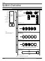
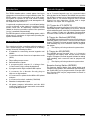
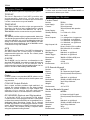
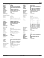
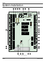
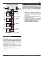
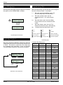
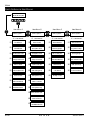
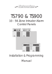
TS2500
Installation & User Guide
Compatible Equipment
NET LCD - Remote Keypad
NETSTAR - Remote Keypad
NETLED - Remote Keypad
NETARM - Remote Keypad
TS700 LEC - 2 Zone Expander
LEC 6 - 6 Zone Expander
LEC 8 - 8 Zone Expander
496513 Issue A
TS900 NODE - 8 Zone Expander
ID NODE - 30 Zone Expander
XNODE - 8 Zone Expander
CPA6 OM - Output Module
DC54/58/58M - Digital Communicators
9040 - Loudspeaker
NIB - Linedriver
1 of 26
TS2500
TS2500
System Overview
System Architecture
Printer
Data
Networks
Speaker
1
Wiring Option 1
XNode
2
2 Outputs
2 Outputs
2 Outputs
XNode
1
XNode
2
XNode
16
Remote
3
CPA6.OM
Aux 12V
Plug-on
Digicom / Modem
TS2500
CONTROL
PANEL
4
5
Bell Output
6
Strobe Output
7
Digi Outputs 1 - 8
8
8 Zones
Remote
Remote
8 Zones
8 Zones
The XNode is capable of driving
4 Remote Keypads and a
Loudspeaker
Outputs 1 - 4
Aux Tamps 1 & 2
Network Wiring = 4 Core
LEC8
LEC8
8 Zones
8 Zones
Wiring Option 2
Remote Keypads or LEC's
1 Output
1 Output
1 Output
1 Output
1 Output
2 Zones
2 Zones
2 Zones
2 Zones
2 Zones
Network Wiring = 6 Core (Remotes) or 4 Core (LECs)
NOTE:
Only one wiring method can be
used on any one Network
Wiring Option 3
Using TS900 Node
2 Outputs
2 Outputs
2 Outputs
2 Outputs
2 Outputs
TS900
Node
1
TS900
Node
2
TS900
Node
3
TS900
Node
4
TS900
Node
5
8 Zones
8 Zones
8 Zones
8 Zones
8 Zones
1 Output
1 Output
2 Outputs
2 Outputs
TS900
Node
4
TS900
Node
5
8 Zones
8 Zones
Network Wiring = 4 Core
Wiring Option 4
2 Outputs
TS900
Node
1
8 Zones
2 Zones
2 Zones
TS900 Nodes and Keypads can be connected on the same Network
BUT NO 2 DEVICES SHOULD HAVE THE SAME ADDRESS.
Network Wiring = 6 Core
Wiring Option 5
8 Outputs
ID Node
2 Outputs
TS900
Node
5
8 Zones
Network Wiring = 4 Core
30 ID Zones
Figure 1: TS2500 System Architecture
TS2500
2 of 26
496513 Issue A
TS2500
Introduction
Remote Keypads
The TS2500 intruder alarm control system has been
designed to suit medium to large installation sites. The
TS2500 system can be expanded up to 1040 zones.
The system is capable of “up” and “down” loading,
allowing remote programming and interrogation via
the telephone line and a P.C.
Up to 5 remote keypads can be connected when
directly wired to the network. The XNODE also provides
the facility to connect up to 4 remote keypads giving a
system total of 512 remote keypads. Each remote
keypad has two detection circuits and a single
switched -ve output. The four types are:
Complex site requirements such as multi-ward setting
can be achieved, as the system is capable of being
broken down into 16 separately controlled areas
(Wards) so that the premises or parts of the premises
can be controlled independently.
32 Character LCD (NETLCD)
The TS2500 system is a true multi-tasking system, which
allows up to a maximum of eight users operating the
system simultaneously.
Control Panel
The control panel is the controlling unit for the system, it
has a power supply and connections for a standby
battery. It has the following facilities:
l 8 networks for connecting remote keypads and
NODEs
The NETLCD remote keypad has a back-lit 32 character
super-twist Liquid Crystal Display (LCD) and a back-lit
tactile rubber keypad. It also has a Loudspeaker output
with a volume control pot. All system programming
must be carried out from a NETLCD remote keypad.
8 Character Starburst (NETSTAR)
The NETSTAR remote keypad has a back-lit 8 character
starburst display (LCD) and a back-lit tactile rubber
keypad. This type of remote keypad is limited to setting
and unsetting only, and cannot be used to program
the system.
The display will always show the system time.
☞
4 Character LED (NETLED)
The NETLED remote keypad has a 4 character
7-segment LED display and back-lit tactile rubber
keypad. This type of remote keypad is limited to setting
and unsetting, and cannot be used to program the
system.
The display will always show the system time.
l
Connections for two 8 zone local expansion cards
(LEC8)
l
Two auxiliary tamper zones
l
Bell and strobe outputs
☞
l
4 programmable outputs (1 x Voltage free
contacts and 3 high current transistorised)
Remote Arming Station (NETARM)
l
8 programmable digicom/RedCARE outputs
l
A connector for a Menvier Security plug-on
digicom or digi-modem
l
A connector for a printer via the MPA or DCI printer
adaptor
l
A connector for mimic modules (CPA6.OM)
l
Extension loudspeaker output
l
All system program information and the 4000
event log is stored in two removable non-volatile
memory (NVM) devices
496513 Issue A
The Remote Arming Station only allows setting and
unsetting of the system. The unit has two indicator LED’s,
the “Power LED” and a programmable “Function LED”
(the “Function LED” may be programmed as “Fault” or
“Area Set” etc.).
3 of 26
TS2500
TS2500
Expansion Devices
NIB Networker Interface Board
There are several options for expanding the system:
A driver and receiver board that allows NODEs or
remotes to be driven up to 1 Km.
TS700 LEC
The Local Expansion Card (LEC) provides two
p r ogr a mm ab le d e t ec t ion circuits and one
programmable switched -ve output. Up to 5 TS700 LECs
can be connected on any one network.
TS900 NODE
The TS900 NODE provides eight programmable
detection circuits and two programmable outputs
(one switched +ve and one switched -ve). Up to 5
TS900 NODEs can be connected on any one network.
XNODE
The XNODE provides eight programmable detection
circuits, two programmable outputs (one switched +ve
and one switched -ve) and a loudspeaker output for
driving a 16 Ohm loudspeaker. Each XNODE can also
drive up to 4 remote keypads. Up to 16 XNODEs can be
connected on any one network.
Technical Specifications
Control Panel
Part No:
Input Supply:
Current:
Power Supply:
Standby Battery:
Zones
Panel Outputs:
Digi Outputs 1-8:
LEC8
The TSLEC8 Local Expansion Card (LEC) is designed to
be fitted inside the control panel it provides 8
programmable detection circuits. The control panel
will accept two LEC8s.
ID NODE
The ID NODE can be used as an alternative to the
standard TS900 NODE. It provides a single ID Detector
Loop for connection to 30 ID devices and 8
programmable outputs. Several options allow it to be
used on its own or with existing TS900 NODEs.
Other Devices
Printer
A DATAC printer or any standard RS232 printer can be
connected to the control panel to obtain system and
log print-outs.
CPA6.OM Output Module
Each output module provides eight switched -ve
outputs, the output modules can be daisy-chained
together to provide multiples of eight outputs. The
outputs can be used to indicate ward status
information and/or circuit alarm/mimic indications.
DC54/58/58M Digicom and Digi-modem
A 4-channel DC54 or 8-channel DC58 digital
communicator can be plugged onto the control panel
to allow alarm status information to be transferred to a
dedicated Alarm Receiving Centre. The 8 channel
DC58M digi-modem can be plugged onto the control
panel, which functions as a digital communicator and
V21 modem. The modem facility is required when
using the up/down loading feature.
TS2500
Speaker Output:
Bell Trigger:
Strobe Trigger:
Dimensions:
Material:
Weight:
Environment:
TS2500
230V ± 10% 50Hz
220mA (normal)
300mA (alarm) with speaker
1.5A
2 x 7.0Ah or 1 x 17Ah
2 to 1040
1 = voltage free changeover
2 = Switched -ve @500mA
3 = Switched +ve @500mA
4 = Switched +ve @500mA
+ve removed
Source 5mA in 12V condition
Sink 100mA in 0V condition
16 Ohms
Switched -ve @500mA
Switched -ve @500mA
384(W) x 312(H) x 95(D) mm
1.2mm mild steel
4.9 Kg
-10° to 55°C
LCD Remote Keypad
Part No:
Display:
Current:
Zones:
Output:
Dimensions:
Material:
Weight:
Environment:
NETLCD
32 Character Liquid Crystal
50mA (normal) 60mA (alarm)
2
Switched -ve @100mA
150(W) x 104(H) x 30(D) mm
3mm Polycarbonate
282g
-10° to 55°C
Starburst Remote Keypad
Part No:
Display:
Current:
Zones:
Output:
Dimensions:
Material:
Weight:
Environment:
4 of 26
NETSTAR
8 Character Liquid Crystal
50mA (normal) 60mA (alarm)
2
Switched -ve @100mA
150(W) x 104(H) x 30(D) mm
3mm Polycarbonate
263g
-10° to 55°C
496513 Issue A
TS2500
LED Remote Keypad
TS900 NODE
Part No:
Display:
Current:
Zones:
Output:
Dimensions:
Material:
Weight:
Environment:
Part No:
Current:
Zones:
Outputs:
NETLED
4 character seven segment
60mA (normal) 70mA (alarm)
2
Switched -ve @100mA
150(W) x 104(H) x 30(D) mm
3mm Polycarbonate
254g
-10° to 55°C
ID NODE
Arming Station
Part No:
Display:
Current:
Zones:
Output:
Dimensions:
Material:
Weight:
Environment:
NETARM
Power LED
Programmable function LED
30mA (normal) 40mA (alarm)
2
Switched -ve @100mA
150(W) x 104(H) x 30(D) mm
3mm Polycarbonate
254g
-10° to 55°C
TS700 LEC
Part No:
Current:
Zones:
Output:
Dimensions:
Material:
Weight:
Environment:
TS700.LEC
30mA (normal) 40mA (alarm)
2
Switched -ve @100mA
142(W) x 82(H) x 36(D) mm
3mm Polycarbonate
213g
-10° to 55°C
XNODE
Part No:
Current:
Zones:
Outputs:
Speaker Output:
Dimensions:
Material:
Weight:
Environment:
496513 Issue A
Dimensions:
Material:
Weight:
Environment:
TS900.NODE
60mA (normal) 60mA (alarm)
8
A = Switched +ve @100mA
B = Switched -ve @100mA
128(W) x 182(H) x 34(D) mm
3mm Polycarbonate
370g
-10° to 55°C
XNODE
60mA (normal) 60mA (alarm)
8
A = Switched +ve @100mA
B = Switched -ve @100mA
16Ohms
128(W) x 182(H) x 34(D) mm
3mm Polycarbonate
370g
-10° to 55°C
Part No:
Current:
Zones:
Outputs:
Dimensions:
Material:
Weight:
Environment:
IDNODE
80mA (with 1 device)
160mA (with 30 devices)
30 (ID)
A = Switched +ve @100mA
B = Switched +ve @100mA
C = Switched +ve @100mA
D = Switched +ve @100mA
E = Switched -ve @100mA
F = Switched -ve @100mA
G = Switched -ve @100mA
H = Switched -ve @100mA
128(W) x 182(H) x 34(D) mm
3mm Polycarbonate
370g
-10° to 55°C
LEC8
Part No:
Current:
Zones:
Dimensions:
Weight:
Environment:
5 of 26
LEC8
20mA (normal) 20mA (alarm)
8
89(W) x 71(H) x 15(D) mm
69g
-10° to 55°C
TS2500
6
H/O H/O
+
-
NETWORK 7
B C/F E/G A
BATT
FAULT
NETWORK 8
B C/F E/G
NETWORK 7 (1 AMP)
KICK
START
TR-
BELL
A
-
SPEAKER
+
NETWORK 6 (1 AMP)
AUX
TAMP 2
B C/F E/G
NETWORK 6
STB
-
AUX
TAMP 1
REM
RESET
-
NETWORK 5 (1 AMP)
B C/F E/G A
TRG
-
8
EPROM LOWER
9
NETWORK 5
AUX
LINE
FLT
+
POWER
+DC
2
3
4 5
6
7 8
DIGITAL COMMUNICATOR
1
NVM LOWER
A
0V 12V
NVM UPPER
NETWORK 4 (1 AMP)
B C/F E/G
0V 12V
AUX
BATTERY
+ -
NETWORK 8 (1 AMP)
A. C.
11
NETWORK 4
EARTH
EPROM UPPER
NETWORK 3
B C/F E/G A
NETWORK 3 (1 AMP)
A
V
7
BELL 12V (1 AMP)
AUX
+4 +3
OUTPUT 1
-2 N/O N/C COM
0V 12V -- OUTPUTS -NETWORK 2
2
AUX 12V (1 AMP)
LEC 2
JP4 LEC 1
JP3
19
B C/F D E/G
NETWORK 2 (1 AMP)
A
JP7
JP9
ENGINEERS REMOTE
NETWORK 1
B C/F D E/G
NETWORK 1 (1 AMP)
A
27
12
26
32
31
22
25
28
496513 Issue A
6 of 26
TS2500
27
2
COMMS PORT
4
3
JP8
20
5
2
JP6
10
26
1
16
13
HEARTBEAT
LED 3
POWER
LED 1
SYSTEM
LEARN
JP5
FACTORY
RESTART
24
JP2
JP1
29
OUTPUT
MODULE
PRINTER
23
15
18
14
17
21
30
DIGI-MODEM
TS2500
System Installation
Figure 2 Main PCB Layout
TS2500
only be used if the device is fitted inside the
control panel housing.
Connection Terminals, Plugs & Indicators
The main PCB has the following connectors etc.
1
12
Networks 1-8
2
Auxiliary 12V
Three sets of auxiliary 12V terminals are provided
on the main PCB, each set provides dc power for
detectors etc. These outputs are protected by a
1A fuse (32).
3
13
Battery Terminals
Earth Terminal
Connection to mains earth.
5
AC Input Terminals
The output from the mains transformer is
connected into these two terminals.
6
7
14
15
9
Speaker Terminals
Auxiliary Tampers 1 & 2
These terminals provide tamper protection to
auxiliary devices such as remote power supplies,
extension loudspeakers etc. If they are not used
they must be linked out.
16
Remote Reset Input
17
Line Fault Input
When this input is applied with a +ve signal the
system will generate a “Line Fault” condition. In
the unset condition the system will generate a
“Chime” tone every minute. In the set condition
any programmed bell delay is cancelled.
11
LEC 1 (JP3) / LEC 2 (JP4)
Two LEC8 PCBs can be connected via an
interface lead to these connectors. The
interface lead is provided with the LEC8.
After a full alarm the system will require resetting,
normally this is done by the engineer or via
coded remote reset. By applying a -ve to this
input terminal it will cause the system to reset
after a full alarm. This input could be connected
to the “Control” output on a RedCARE STU so that
the central station can provide a “Remote Reset”
facility.
10
Output Module (JP2)
Output modules type CPA6.OM can be
connected to this 5-pin plug, and are used to
provide switched -ve outputs to LED's/relays etc.
The outputs can be programmed such that they
give ward status information and/or circuit
mimic/alarm indications.
Up to two 16 ohm extension loudspeakers can
be connected across these two terminals. The
volume is controlled via a programming option.
8
Printer Output Port (JP1)
This 6-pin plug is used for connecting to either a
CPA6 printer or a standard RS232 printer via the
DCI/MPA printer adaptor.
External Sounder Terminals
This group of terminals are used for connection
to an external sounder.
Panel Outputs 1 to 4
These are programmable outputs that can be
used to drive relays and auxiliary equipment.
Output [1] is a set of voltage free change over
contact rated at 1Amp. Output [-2] is a switched
negative output rated at 500mA. Outputs [+3]
and [+4] are switched positive outputs rated at
500mA.
Connection terminals for the red and black
battery leads supplied inside the spares pack.
4
Digicom Outputs 1 to 8
These are programmable outputs and are
normally connected to the input channels on a
stand-alone digital communicator or RedCARE
STU. The outputs are normally at +12V and switch
to 0V when active. The outputs can be inverted
so that they switch from 0V to +12V when active
Each output will source 5mA in the +12V
condition and sink 100mA in the 0V condition.
Data networks for connecting NODEs, remote
keypads and LECs. Each network is protected by
its respective fuse (30), the fuse is in-line with the
[A] connection of the network
+DC Power
Factory Restart (JP5)
If these pins are shorted during power-up all
system parameters are reset to their factory
default settings. If the engineer’s passcode is lost
or forgotten it can be reset to 1234 without losing
any other program data as follows:
(a) Ensure that the system is fully unset and a user
passcode is available.
(b) Remove the cover from the control panel, this
will cause a panel lid tamper alarm.
(c) Enter a user passcode to silence the alarm.
(d) Place the blade of a small screwdriver
between the “FACTORY RESTART” pins. A
multi-tone sound indicates that the engineer’s
passcode has been reset. This action will be
recorded in the system log.
This terminal provides the +12V power to the
stand-alone digital communicator or RedCARE
STU. This output is un-fused and therefore must
496513 Issue A
7 of 26
TS2500
TS2500
18
System Learn (JP6)
26
If these pins are shorted whilst the system is
powered, the control panel will re-learn all
devices on all eight networks. If after a system
learn the number of devices or device types
have changed the display will show "RELEARN
REQUIRED". In order to clear this message you
must confirm the number of network device
using the "Confirm Network Devices" option.
19
20
27
28
29
Engineer’s Remote Keypad Plug (JP9)
Normally all system programming will be carried
out from one of the installed remote keypads.
However, an engineers remote keypad can be
temporarily connected to this 6-pin plug to allow
programming and testing to be carried out at
the control panel. This feature can only be used if
Network 1 does not have any XNODEs
connected to it, or any keypads addressed as
'ENG' or LECs addressed as 'NULL'.
22
Tamper Switch
The lid tamper protection for the control panel.
Network Fuses 1 to 8
The supply voltage across [A] and [B] terminals
each network is protected by its own fuse
(1Amp).
High speed serial communications port COM1
(for future use).
21
System Current Measurement (V)
The system current consumption can be
calculated by measuring the voltage across this
test point on the main PCB. Using a Voltmeter set
to a low Voltage range measure the Voltage
across the test point and multiply the reading by
10 to give the Total system current consumption
i.e. a reading of 70mV = 700mA.
30
Comms Port (JP8)
EPROM Upper & Lower
Two removable memory devices that store the
operating software for the TS2500 system.
Digi-Modem Plug (JP7)
A plug-on digicom or digi-Modem may be
connected to this 7-pin plug to allow panel
alarm information to be transferred to an alarm
receiving centre. The digi-Modem is used for
remote communication and programming via
a PCI/DCI lead also available, which connects to
this plug when using a P.C. with Lineload
software for direct communication with the
control panel.
NVM Upper & Lower
Two removable non-volatile memory (NVM)
devices that store all system program
parameters and the 4000 log events.
31
Bell Fuse
The supply voltage across the [H/O+] and [H/O-]
terminals that supply the external sounder is
protected by this 1 Amp fuse.
32
Aux 12V Fuse
The supply voltage across the auxiliary 12V
terminals are protected by this 1 Amp fuse.
Kick Start (JP10)
If the system is to be powered only from the
battery (no mains supply available) then the
“Kick Start” pins must be momentarily shorted to
enable the battery.
23
Power LED
This LED indicates that the system power (mains
or battery) is healthy.
24
25
Heartbeat LED
When the system is functioning correctly this
LED will continually flash on and off. If a fault
occurs on the main PCB this LED will stop
flashing.
Battery Fault
If the system battery is incorrectly connected to
the control panel the “Battery Fault” LED will
illuminate. The fault LED will only extinguish when
the battery has been correctly connected or
replaced.
TS2500
8 of 26
496513 Issue A
TS2500
Output Modules
100m
PL2
Connect to plug
labelled OUTPUT
MODULE
+12V IN
Plug-on digicom / digi-modem
1 2 3 4
+12V OUT
PL1
+12V OUT
DC54/DC58 Plug-on Digicoms
A plug-on digital communicator DC54 or DC58 can be
fitted inside the control panel to allow alarm status
information to be transferred to a dedicated Alarm
Receiving Centre. The unit should be fitted in
accordance with the installation instructions supplied
with it and connected to the control panel plug
DIGI-MODEM (JP7) using the lead provided with the unit.
The NVM within the digicom can be programmed via
the control panel.
5 6 7 8
1k Resistors
LED's
A
B
BC
Connect to JP7
DIGI-MODEM
Figure 5 Output module Connections
The Output Module provides eight switched -ve outputs
each rated at 100mA. They can be used to drive LED's
or relays etc. Each module is supplied with an interface
lead which allows it to be connected to the control
panel or XNODE. Output modules are normally fitted
inside the equipment they are controlling and can be
positioned up to 100 metres away.
Telephone cable
(Type 1/0.5mm CW1308)
6
5
4
White / Blue ring
3
2
1
Blue / White ring
Orange / White ring
B.T. master jack ( Type NTE5
user accessible connections )
Control Panel Connections
Figure 3 DC54/DC58 Connections
When connected to the control panel the output
modules can be programmed to give ward status
indications and/or circuit mimic/alarm indications.
DC58M Plug-on Digi-Modem
A plug-on digi-modem DC58M can be fitted inside the
control panel to allow remote interrogation and
programming via a personal computer (PC). It will also
function as a standard digicom (if required). The unit
should be fitted in accordance with the installation
instructions supplied with it and connected to the
control panel plug DIGI-MODEM using the lead
provided with the DC58M. The NVM within the
digi-modem can be programmed via the control
panel . The modem data is also programmed via the
control panel.
XNODE Connections
When connected to the XNODE, the output module will
provide circuit mimic indications for the eight
detection circuits of the XNODE.
TS2500 Control
Panel
DC58M
Telephone
Network
Alarm Receiving
Centre
V21.
Modem
Figure 4 DC58M Digi-modem Schematic
496513 Issue A
9 of 26
TS2500
TS2500
Network Wiring
1 Km (Max.)
100 metres
Control Panel
Data
Network
4-Core
100 metres
100 metres
100 metres
XNode
XNode
XNode
XNode
I/D=1
I/D=2
I/D=3
I/D=4
Out
In
In
Out
In
Out
Out
In
XNode
I/D=16
XNodes
5 to 16
In
Out
Daisy-chained Connections
1 Km (Max.)
100 metres
Control Panel
Data
Network
4-Core
100 metres
100 metres
100 metres
100 metres
XNode
XNode
XNode
XNode
I/D=1
I/D=3
I/D=6
I/D=7
In
Out
In
Out
In
Out
Out
In
XNode
XNode
XNode
I/D=2
I/D=4
I/D=9
In
Out
In
Out
In
Out
XNode
I/D=8
In
Out
XNode
I/D=10
In
Out
NOTE:
The maximum number of devices
that can be "Star" connected from
the output of the Node or control
panel is 4.
XNode
XNode
I/D=11
I/D=5
In
Out
In
Out
Star and Daisy-chained Connections
Figure 6 XNODE Connection Methods
XNODE Wiring
The XNODE requires a 4 core cable for interconnection,
and up to 16 may be connected in a “daisy-chain” or
“star” configuration. The distance between each
XNODE must not exceed 100 metres. The total
distance to last XNODE must not exceed 1000 metres.
Power for detectors is provided by the Aux. +/terminals.
Wiring Remote Keypads to an XNODE
Up to four remote keypads can be connected to each
XNODE, they can be connected in either a “star” or
“daisy-chain” configuration. The distance to the
furthest remote keypad from the XNODE must not
exceed 100 metres. Power for detectors are provided
by the A(+) and B(-) terminals.
The detection circuits in the XNODE can either be
mapped to the XNODE or the the remote keypads by
setting the 4-way “Remote Zone Enable” switch as
shown in the table above:
TS2500
Switch
1
2
3
4
OFF
XNODE circuits A &
B enabled
XNODE circuits C &
D enabled
XNODE circuits E & F
enabled
XNODE circuits G &
H enabled
ON
Remote keypad 1
circuits A & B enabled
Remote keypad 2
circuits A & B enabled
Remote keypad 3
circuits A & B enabled
Remote keypad 4
circuits A & B enabled
☞
Remote keypads cannot be multi-tasked
between each other when connected to the
XNODE, i.e. If remote keypad 1 is in operation,
remote keypads 2, 3 and 4 are locked-out and
will show “SYSTEM IS BUSY PLEASE WAIT”.
☞
Th e remot e keypads fol l ow t he ward
assignment of the XNODE, i.e. If the XNODE is
assigned to ward A then remote keypads 1-4
connected to that XNODE are also assigned to
ward A.
☞
The loudspeaker and remote keypad sounders
will follow the ward assignment of the XNODE.
☞
The programmable output on the remote
keypads are mapped as follows: Remote
keypads 1 and 3 follow XNODE output A and
remote keypads 2 and 4 follow XNODE output
B.
10 of 26
496513 Issue A
TS2500
Wiring NODEs and Remote Keypads
XNode
In
Out
A
B
F
G
From
control
panel
Remote Keypad Network
ABCDE
G
F
B
A
To
next
XNode
6 Core
Alarm Cable
100 metres (Max.)
I/D=1
A
Remote B
Keypad C
D
E
+12V
0V
Power for
detectors
Spare core used to double
up "B" to reduce voltage drop.
I/D=2
A
Remote B
Keypad C
D
E
+12V
0V
Power for
detectors
+12V
0V
Power for
detectors
I/D=3
A
Remote B
Keypad C
D
E
+12V
0V
I/D=4
A
Remote B
Keypad C
D
E
Power for
detectors
The TS900 NODE and remote keypads can be
connected on the same network. The network must be
wired in 6-core cable to allow the remote keypad
internal sounders to operate.
No two devices should have the same address
(I/D).
☞
☞
This method of connection is designed for
networks 1 and 2. Although it can be used on
other networks, the “D” connection for the
remote keypads will have to be taken from
networks 1 or 2.
☞
The sounder on the remote keypads will follow
the control panel sounder.
☞
Remote keypads cannot be multi-tasked
between each other on the same network
when using this method of connection.
☞
The maximum number of devices is five.
Figure 7 Wiring Remote Keypad to an XNODE
TS900 NODE Wiring
T S 9 0 0 N ODE req uires a 4 core cable for
interconnection, and up to 5 may be connected in a
“daisy-chain” or “star” configuration to any one network.
The distance between each NODE must not exceed
100 metres and the total distance to last NODE must
not exceed 500 metres. Power for detectors is
provided by the Aux. +/- terminals.
The TS900 NODE has two programmable outputs, each
rated at 100mA, output[A+] is a switched +ve output
and output [B-] is a switched -ve. The outputs can be
used to drive sounders or relays etc.
No two devices should have the same address
(I/D).
☞
☞
The maximum number of devices is five.
496513 Issue A
11 of 26
TS2500
TS2500
500 meters (Max.)
100 metres
100 metres
Control Panel
TS900
Node
A
B
F
G
4 Core
I/D=2
I/D=3
I/D=4
TS900
Node
TS900
Node
TS900
Node
Out
In
Out
In
A
B
F
G
A
B
F
G
A
B
F
G
4 Core
100 metres
100 metres
100 metres
I/D=1
Out
In
A
B
F
G
A
B
F
G
4 Core
A
B
F
G
4 Core
TS900
Node
Out
In
A
B
F
G
I/D=5
A
B
F
G
Out
In
A
B
F
G
4 Core
A
B
F
G
Data
Network
TS900 Node Connections
100 metres
100 metres
Control Panel
I/D=5
TS900
Node
TS900
Node
TS900
Node
In
Out
A
B
F
G
Networks
1 or 2
100 metres
I/D=3
In
A
B
C/F
E/G
D
100 metres
I/D=1
In
Out
A
B
F
G
A
B
F
G
A
B
F
G
Out
A
B
F
G
A
B
F
G
Terminal strip
I/D=2
I/D=4
Remote Keypad
Remote Keypad
A
B
C
D
E
A
B
C
D
E
100 metres
100 metres
TS900 Nodes and Remotes Connected on the same Network
Figure 8 TS900 NODE Wiring Options
Remote Keypads and TS700.LECs
Up to 5 remote keypads or TS700.LECs can be
connected on any network. The devices may be wired
in a “daisy-chain” or “star” configuration. When using
remote keypads the network must be wired in 6-core
cable.
If all devices on the network are TS700.LECs the network
can be wired in 4-core as the “D” connection is not
required.
No two devices should have the same address
(I/D).
☞
100 Metres (Max.)
Spare Core
I/D=1
I/D=2
I/D=3
I/D=4
Remote
Keypad
or LEC
Remote
Keypad
or LEC
Remote
Keypad
or LEC
Remote
Keypad
or LEC
Remote
Keypad
or LEC
A B CD E
A B CD E
A B CD E
A B CD E
A B CD E
Control Panel
Data
Network
I/D=ENG
A
B
C/F
D
E/G
Power For
Detectors
Power For
Detectors
Power For
Detectors
Power For
Detectors
Power For
Detectors
Figure 9 Wiring Remote Keypads or TS700.LECs
TS2500
12 of 26
496513 Issue A
TS2500
Wiring Detection Circuits
Default Table
Section
All detection circuits may be wired as “End of Line” (EOL)
OR “Double Pole” (DP). Both methods can be used on
the same equipment. Please refer to Network Devices,
Wiring Section for more details.
Default NVM Data
[1-B]
The default NVM data option allows the engineer to
reset the NVM data back to the factory defaults. The
initialisation procedure has been broken down into
specific sections so that the engineer can reset all data
or specific areas.
Custom Text
Option
Default
Reset Message
CALL ENGINEER TO
RESET SYSTEM
Location Text
PANEL LOCATION
TEXT NOT SETUP
Printer Header
MENVIER SECURITY
TS2500 SYSTEM
Printer Prefix
Blank
Banner Message
Blank
Part Set Banner
Blank
Aux Tamper 1
Blank
Aux Tamper 2
Blank
Remote Reset Msg RING A.R.C FOR
REM. RESET CODE
Engineers menu 1
Default NVM data
[
Modem Data
[ENT] to DEFAULT
Custom text?
A / C to scroll through
User Codes
options.
[ to DEFAULT.
[ENT] to DEFAULT
Modem data?
]
Reset User Code Flowchart
Configuration
496513 Issue A
13 of 26
Modem String
Blank
Call Back No.1
Blank
Call Back No.2
Blank
Call Back No 3
Blank
Modem Password
Blank
Modem Site No.
Blank
User 000 Engineer
1234
User 001 Master
5678
User 002 - 199
Not used
00
Bell is an SAB
01
View alms P.Set
02
Duress Disabled
03
Engr Authorised
04
On-Line Enabled
05
Lo-sec Engineer
06
Normal answer
07
Unset ward first
08
Can set with L.F.
09
Can set - AC off
10
Quiet chimes
11
O/P 1 normal
12
Digi normal
13
4 digit codes
14
Modem on Com1
15
Chime Audible
16
Manual Omits
17
Omits Tampers No
18
O/M’s mimic cct
19
Log Time & Date
20
Global Setting
TS2500
TS2500
Section
Configuration
Outputs
Option
Default
Section
Option
Default
21
Global Unsetting
2nd Entry delay
015 Seconds
22
24hr Omit Global
Double Knock dly
010 Seconds
23
Ward bell time
Abort duration
010 Seconds
24
Latching Fire
Abort delay
180 Seconds
25
Online Printing
2nd alarm Time
060 Seconds
26
Timed code o/p
Courtesy time
120 Seconds
27
Activity flt ok
Access code time
005 Seconds
28
Latching 24hr
Menu time-out
180 Seconds
29
Access code only
Line fault delay
030 Seconds
30
Answer anytime
AC off delay
030 Seconds
31
NVM is Unlocked
Monitor cct time
060 Seconds
32
Unshunt & No exit
Beam pair time
010 Seconds
33
Ignore errors
Battery test dur
030 Seconds
34
Mimic. All times
Answer ring time
030 Seconds
Panel Output 1
Walk Test
Global bell dly
000 Minutes
Panel Output 2
Courtesty Light
Global dell dur
020 Minutes
Panel Output 3
Switch 12 Volts
Panel Output 4
System Timers
Activity delay
060 Minutes
Detector Reset
Defer setting by
010 Minutes
Digicom Output 1
Fire Alarm
Battery test
060 Minutes
Digicom Output 2
Panic Alarm (PA)
Hi Security time
000 Minutes
Digicom Output 3
Alarm
Cct test time
014 Days
Digicom Output 4
System Set
Service time
000 Days
Digicom Output 5
Engineer on site
Payment time
000 Days
Digicom Output 6
Bell (SAB)
Test call every
000 Days
Digicom Output 7
Tamper Alarm
Select menu time
010 Seconds
Digicom Output 8
2nd Alarm
Custom o/p 2 Tmr
000 Seconds
Digi Channel 1
Fire Alarm
Number of reams
003
Digi Channel 2
Panic Alarm (PA)
Modem rings
000
Digi Channel 3
Alarm
Keys unit tamp
017
Digi Channel 4
System Set
Remote resets
032
Digi Channel 5
Engineer on site
Reset algorithm
004
Digi Channel 6
Bell (SAB)
Double Knock
002
Digi Channel 7
Tamper Alarm
Digi Channel 8
2nd Alarm
All NODE Outputs
Circuit 0001 Alarm
All Remote Outputs Circuit 0001 Alarm
Custom Outputs 1-8 Circuit 0001 Alarm
Setting Modes
System Timers
TS2500
All Wards
Timed Exit
Exit time wards A-P
030 Seconds
Entry dly wards A-P
015 Seconds
Digi dly wards A-P
000 Seconds
Bell dly wards A-P
000 Minutes
Bell dur wards A-P
020 Minutes
Exit settle time
005 Seconds
14 of 26
496513 Issue A
TS2500
Section
Option
On times 1,2 & 3
Time Switches
Code Locks
Auto-set Times
Off times 1, 2 & 3
00:00
Timers operate on
No days
Time switch output
Off
On times 1, 2 & 3
00:00
Off times 1, 2 & 3
00:00
Timers operate on
No days
Time lock output
Off
User assigned
None
Set times 1, 2 & 3
00:00
Unset times 1, 2 & 3 00:00
Timers operate on
No days
Wards assigned
None
Custom Circuits Circuits 1-8
Circuits
Equipment
Wards
Default
00:00
Not defined
Circuits 0001 - 8128 Not Used
Panel tamper
Ward A
Bell box tamper
Ward A
Aux 1 tamper
Ward A
Aux 2 tamper
Ward A
Phone line fault
Ward A
Mains power off
Ward A
Payment timer
Not assigned
Alarms Eng Reset
Not assigned
Tamper Eng Reset
Ward A
Remote reset
Ward A
Panel speaker
Ward A
Relearn required
Not assigned
Re-arms apply to
Ward A
Hi Security ward
Not assigned
Relearn Required
Not assigned
Re-arms apply to
Ward A
Hi Security ward
Not assigned
Digi in Part Set
Wards A-P
System Bell/STB
Wards A-P
Ward A foyer Mode Not assigned
Unset fire sig.
Dble knock wards
Net Equipment All new devices
Part Set Group Part set groups 0-9
Log
496513 Issue A
All 4000 Events
Not assigned
Not assigned
Ward A
Not Defined
No Event
15 of 26
TS2500
TS2500
Log Event Codes
Event
—- NO EVENT —#### ACTIVATED
#,## LEC LOST
### LEC or REM’S
#,## NODE ADDED
#,## NODE LOST
### NODE’S
### XNODE’S
#### OFF TEST
#### OMITTED
#### REINSTATED
#,## REM ADDED
#,## REM LOST
#### SHUNTED
#,## XNODE ADDED
#,## XNODE LOST
24Hr ALARM ####
24Hr OMITTED:
24Hr REINSTATED:
24Hr WARDS:ABORT ON WARDS:ABORTED ERRORS
ACCESS ###
ACCESS FAILED
ALARM ####
ALARM WARDS:AUTOSET # OFF
AUTOSET # ON
AUXILIARY ####
AUXILIARY # TAMP
AUXILIARY FUSE
BATTERY FAULT
BATTERY RESTORE
BEAM PAIR ####
BELL BOX TAMPER
BELL TESTED:BELLS ACTIVE:CALL ABORTED
CALLED No. #
CALLING BACK No. #
CCT ON TEST ####
CCT TESTED ####
CCTS REINSTATED
CIRCUITS SHUNTED
CODE LOCK # OFF
CODE LOCK # ON
CODE LOCKED ###
TS2500
Description
No event
Monitored circuit activated
Network #, device No. ## is a LEC that has been removed
The number of LEC or REM’s logged on to system after a re-learn
Network #, device No. ## is a TS900 NODE that has been added to the system
Network #, device No. ## is a TS900 NODE that has been removed
The number of TS900 NODEs logged on to the system after a re-learn
The number of XNODEs logged on to the system after a re-learn
Circuit number #### taken off test
Circuit number #### omitted
Circuit number #### reinstated
Network #, device No. ## is a remote keypad that has been added to the system
Network #, device No. ## is a remote keypad that has been removed
Circuit number #### shunted
Network #, device No. ## is a XNODE that has been added to the system
Network #, device No. ## is a XNODE that has been removed
24hr alarm from circuit number ####
24Hr group omitted in wards:- A - P
24Hr group reinstated in wards:- A - P
24hr Alarm on wards:- A - P
Alarm aborted on wards:- A - P
Remote service errors
Access passcode ### entered.
Access failed due to code lock in operation
Alarm from circuit number ####
Alarm in wards:- A - P
Autoset timer 1-3 off
Autoset timer 1-3 on
Auxiliary alarm from circuit number ####
Auxiliary 1 or 2 tamper
Auxiliary Fuse failed
Battery disconnected or voltage level below 9.5V
Battery restored to healthy condition
First activation of a beam pair circuit number ####
External sounder/bell tamper
Bell tested for wards:- A - P
Bell active for wards:- A - P
Remote service call aborted
Remote service call initiated via panel to remote PC 1, 2 or 3
Remote service call requested via PC to “Call back No” 1, 2 or 3
Circuit number #### put on test
Circuit number #### tested during walk test routine
Circuits reinstated with a shunt code
Circuits shunted with a shunt code
Code lock number # is off
Code lock number # is on
User number ### attempted to use their passcode whilst locked-out
16 of 26
496513 Issue A
TS2500
Event
CODE TAMPER
COMMS FAILED
COMMS SUCCESSFUL
DATE CHANGED
DEFAULT USER ###
DEFERRED SET:DIGI-COM FITTED
DIGI/MODEM LOST
DIGI/MODEM RESET
DURESS CODE ###
ENGINEER ARRIVES
ENGINEER DEPARTS
ENTRY ####
ENTRY TIME-OUT:ENTRY WARDS:EXIT CANCELLED:EXIT STARTED:FACTORY RESTART
FIRE ALARM ####
FIRE WARDS:FIRST KNOCK ####
From Remote #,##
Hi Security SET:
LEC #,## TAMPER
LINE RESTORE
LINK ESTABLISHED
MAINS POWER OFF
MAINS POWER ON
MENU TIMEOUT ###
MODEM FITTED
MODEM LOCK-OUT
NODE ### R# ADD
NODE ### R# LOST
NODE ### R# TAMP
NODE #,## FUSE
NODE #,## TAMPER
NODE SHUNT ####
ON-LINE ENDED
ON-LINE TO No.#
ON-SITE RESTART
PA ALARM ####
P.A CODE ###
PA WARDS:PANEL LID TAMPER
PASSCODE ###
PAYMENT EXPIRED
PC CONNECTED
PC DISCONNECTED
496513 Issue A
Description
Keypad locked out for 5 minutes due to invalid entry of passcode
Plug-on digicom failed to communicate with ARC
Plug-on digicom communicated successfully with the ARC
System date changed
User 001 defaulted to 5678
Deferred set on wards:- A - P
Plug-on digicom fitted
Plug-on digicom or modem removed
Plug-on digi-modem reset
Duress alarm from user number ###
Engineer is logged on the system
Engineer is logged off the system
Entry mode started from circuit number ####
Entry mode timed out for wards:- A - P
Entry on wards:- A - P
Exit mode cancelled for wards:- A - P
Exit mode started for wards:- A - P
Factory defaults loaded
Fire alarm from circuit number ####
Fire alarm on wards:- A - P
First activation of circuit number #### (circuit with Double-Knock attribute)
Quick set performed from remote keypad (# = Network, ## =device No)
Wards A - P set using “High Security” feature
Network #, LEC number ## lid tamper alarm
Telephone line restored to healthy
Remote link via PC established
Mains power removed from control panel
Mains power applied to control panel
User number ### entered their passcode and did not selected any functions
Plug-on digi-modem fitted
Modem locked-out (4 failed attempts made via Lineload)
Remote keypad added to XNODE
Remote keypad removed from XNODE
Remote keypad lid tamper from remote on XNODE
TS900 NODE fuse failed
TS900 NODE lid tamper
Circuits shunted on a NODE
Remote service call ended (PC and Lineload)
On-line to remote PC
On-site restart
PA Alarm from circuit number ####
PA code from user number ###
PA alarm on wards:- A - P
Control panel lid tamper
User number ### entered their passcode
System payment timer has expired
PC connected to control panel (PCI/DCI)
PC disconnected from control panel (PCI/DCI)
17 of 26
TS2500
TS2500
Event
Description
PHONE LINE FAULT
Telephone line fault detected
QUICK SET KEY #
Quick set key A, B or C activated
Q.SET ABORTED
Quick set key aborted
REARM ON WARDS:-
Wards:- A - P re-armed
REINSTATED WARDS
Wards A - P reinstated
REM #,## TAMPER
Remote keypad lid tamper
REM RESET ACTIVE
Remote reset via the REM RESET input terminal (RedCARE)
REM RESET FAILED
Remote Reset failed
REM SERVICE CALL
Remote service call in progress
RESET WARDS:-
User or engineer has reset wards:- A - P
SEC. KEY ####
Security key operated on circuit number ####
SERVICE CALL END
Remote service finished
SERVICE REQUIRED
System requires a service visit (Service Timer expired)
SET FAIL WARDS:-
Set fail for wards:- A - P
SET FAIL ####
Set fail caused by circuit ####
SET NO ACTIVITY
System was set with inactive circuits (circuits with the activity attribute)
SET WARDS:-
Wards set:- A - P
SET WITH L.FLT:-
Wards A - P set with a line fault present
SETTING DEFERRED
Setting deferred
SHUNT CODE ###
Shunt code number ### entered their passcode
SHUNT KEY ####
Shunt key circuit #### operated
SYSTEM RELEARN
A system relearn has been performed
T.SWITCH # OFF
Time switch number # off
T.SWITCH # ON
Time switch number # on
TAMPER ####
Tamper alarm from circuit number ####
TAMPER WARDS:-
Tamper alarm on wards:- A - P
TEST FAIL ####
Circuit number #### failed whilst on test
TEST TOTAL ####
Total number of circuit tested during walk test
TIME CHANGED
System time changed
UNSET WARDS:-
Wards:- A - P unset
USER ### DELETED
User number ### deleted
WALK TESTED:-
Wards:- A -P walk tested
WARD KEY ####
Ward key circuit #### operated
WARDS LOCKED:-
Wards:- A - P locked via security key circuit
WARDS UNLOCKED:-
Wards:- A - P unlocked via security key circuit
XNODE #,## FUSE
XNODE fuse failed
XNODE #,## TAMP
XNODE lid tamper
TS2500
18 of 26
496513 Issue A
TS2500
Key Functions
Engineer’s Reset
1.
2.
Loading Defaults
Key in engineer code default 1234. Display
shows “Engineer’s Menu 1”.
Press ] display shows “Engineer Onsite”.
To return panel to factory defaults:
1. Power down panel
2. Short factory restart pins
This message will be cleared the next time a valid user
passcode is entered or by exiting the engineer's menu
3. Power up battery & mains
1 by pressing C and then [.
4. Remove short
5. Enter 1234 to silence sounders
Relearn Required Message
6. Replace the control panel cover. At the remote
keypad enter 1234. The display will show
“Engineer’s menu 1”.
When the system is powered up after a factory restart,
the remote keypads will display “RELEARN REQUIRED”.
On entering your engineer’s passcode the system will
automatically select the “Confirm Network Devices”
option. After confirming the correct number of devices
the “RELEARN REQUIRED” message will be cleared.
Once cleared, entering your engineer’s passcode will
select “Engineer’s Menu 1”.
Resetting the Engineer’s Passcode
If the installation engineer has inadvertently changed
the engineer’s passcode or the passcode has been
forgotten, the passcode can be reset back to 1234
without losing any other programmed data. This
procedure can only be used providing a user
passcode is available:
1.
Ensure that the system is unset and a user
passcode is available.
2.
Remove the cover from the control panel, this
will cause a “Panel Lid Tamper” alarm.
3.
Ask the user to enter their passcode to silence
the alarm.
4.
Place the blade of a small screwdriver between
the pins labelled “FACTORY RESTART”. A multi-tone
sound indicates the engineer’s passcode has
been reset.
5.
Initial Power-Up
To power up the system for the first time:
1. Place a small screwdriver blade between
the pins on the control panel PCB, marked
“FACTORY RESTART”. This will ensure the
factory default parameters are set.
2. Switch on the 230V mains supply and remove the
screwdriver blade after 5 seconds.
3. Check that the power LED on the control panel PCB
is illuminated.
4. Check that the remote keypads display “Panel Lid
tamper”. The remote keypad sounders and
extension loudspeakers will be operated.
5. Enter the engineer’s passcode (default 1234)
to silence the sounders.
6. Connect the standby battery.
Bell Test/Walk Test
Please refer to User Menu 1, No’s 1 & 2 respectively.
Replace the control panel cover. At the remote
keypad enter 1234. The display will show
“Engineer’s Menu 1”.
496513 Issue A
19 of 26
TS2500
TS2500
Log Off Engineer
Programming Text
Selecting this option will log off all engineers and return
the system to the “SYSTEM OPEN” condition.
When programming any text the keys on the keypad
function as shown below: Cursor Types
C
[^]
This is the normal text editing cursor. Use
the text editing keys as shown below.
[|]
Engineers menu 1
Log off engineer
This is the number cursor. Use the
numbered keys 0 - 9 to enter numeric
data.
[+]
[
This is the insert cursor. Use text editing
keys as shown above to insert text at the
cursor.
[-]
This is the delete cursor. Use key [7] to
delete from the left of the cursor and key
to delete from the right of the cursor.
SYSTEM OPEN
18:10 Sun 01 JAN
[9]
1 =A
2 =E
3 =I
4 =O
5 =U
6 = 0 (zero)
7 = Move cursor left
8 = Change case
ENT
Log Off Engineer flowchart
9 = Move cursor right
0 = Space
= Accept text
ESC
A = Up the alphabet B = Change cursor
Reset User Code 1
Text Editing Keys
This option allows the installation engineer to reset the
master user (user 01) back to the factory default code
of “5678”. This feature is useful when the master user
has forgotten their passcode or has accidentally
changed it without realising. This operation is logged.
B
Common Key Sequences
Character
Engineers menu 2
Reset user code1
[
[ENT] to DEFAULT
user code 1.
[ = Reset code
Reset User Code Flowchart
TS2500
= Abandon text editing
C = Down the alphabet
20 of 26
Key Sequence Character
Sequence
A
1
U
5
B
1A
V
5A
C
1AA
W
5AA
D
2C
X
5AAA
E
2
Y
5AAAA
F
2A
Z
5AAAAA
G
2AA
:
1CCCCCCC
H
3C
;
1CCCCCC
I
3
<
1CCCCC
J
3A
=
1CCCC
K
3AA
>
1CCC
L
3AAA
?
1CC
M
4CC
@
1C
N
4C
!
0A
O
4
"
0AA
P
4A
#
0AAA
Q
4AA
$
0AAAA
R
4AAA
%
0AAAAA
S
5CC
&
0AAAAAA
T
5C
496513 Issue A
TS2500
Engineer’s Quick Reference
Hotkey
Engineers Menu 1
Hotkey
1
2
3
4
7
Options
Program Panel Outputs
1 = Panel Output 1 (relay)
2 = Panel Output 2 (-ve)
3 = Panel Output 3 (+ve)
4 = Panel Output 4 (+ve)
8
Program Digicom Outputs
1 = Output 1
2 = Output 2
3 = Output 3
4 = Outrput 4
5 = Output 5
6 = Output 6
7 = Output 7
8 = Output 8
9
Program Digicom Channels
1 = Channel 1
2 = Channel 2
3 = Channel 3
4 = Channel 4
5 = Channel 5
6 = Channel 6
7 = Channel 7
8 = Channel 8
Program Circuits, Attributes & Wards
Circuit Types
0 = Not Used
1 = Night
2 = 24 Hour
3 = PA Silent
4 = PA Audiible
5 = Fire
6 = Auxiliary
7 = Final Exit
8 = Exit Terminator
9 = Ward Key
A/C = Shunt Key
A/C = Tamper
A/C = Security
A/C = 24hr Silent
A/C = Night Perimeter
A/C = Custom circuits
Circuit Attributes
1 = Access
2 = Double Knock
3 = On Test
4 = Omittable
5 = Reset
6 = Activity
7 = Entry
8 = Chime 1
9 = Chime 2
A/C = Chime 3
A/C = Inverted
A/C = Shuntable
A/C = Beam Pair
A/C = Eng. Test
A/C = Monitored
A/C = Non Latching
B = Toggle attribute between YES/NO
Wards
1 - 8 = Select/deselect wards displayed
A/C = Toggle wards A-H or I-P
B = Select/deselect all wards
5
6
Program System Timers
Exit time wards A-P
Entry dly wards A-P
Digi dly wards A-P
Bell dly wards A-P
Bell dur wards A-P
Exit settle time
2nd Entry delay
Double Knock dly
Abort duration
Abort delay
2nd alarm time
Courtesy time
Access code time
Menu time-out
Line fault delay
AC off delay
Monitor cct time
Beam pair time
Battery test dur
Answer ring time
Global bell dly
Global bell dur
Activity delay
Defer setting by
Battery test
Hi Security time
Cct test time
Service time
Payment time
Test call every
Select menu time
Custom o/p 2 Tmr
A
B
C
0
Program Setting Modes
A/C =Select ward
1 = Final Exit
2 = Exit Terminator
3 = Timed Exit
4 = Instant
5 = Deferred
496513 Issue A
21 of 26
Options
System Print-out
0 = Custom text
1 = Modem data
2 = User codes
3 = Configuration
4 = Outputs
5 = Setting modes
6 = System timers
7 = Time switches
8 = Code locks
9 = Auto-set times
A/C = Custom Circuits
A/C = Circuits
A/C = Equipment wards
A/C = Net equipment
A/C = Part set groups
Program System Options
Number of rearms
Modem rings
Keys until tamp
Remote resets
Reset algorithm
Double Knocks
Program Configuration
00 = Bell is an SAB / Bell is an SCB
01 = View alms P.Set / View alms unset
02 = Duress Disabled / Duress Enabled
03 = Engr Authorised / User Authorised
04 = On-Line Enabled / On-Line Disabled
05 = Lo-sec Engineer / Hi-sec Engineer
06 = Normal answer / Timed answer
07 = Unset ward first / Set ward first
08 = Can set with L.F / No set with L.F
09 = Can set - AC off / No set - AC off
10 = Quiet chimes / Loud chimes
11 = O/P 1 normal / O/P1 inverted
12 = Digi normal / digi inverted
13 = 4 digit codes / 6 digit codes
14 = Modem on Com1 / Printer on COM1
15 = Chime Audible / Chime Visible
16 = Manual Omits / Automatic Omits
17 = Omit Tampers No / Omit Tampers Yes
18 = O/M's mimic cct / O/M’s mimic alms
19 = Log Time & Date / Log Time & Day
20 = Global Setting / Local Setting
21 = Global Unsetting / Local Unsetting
22 = 24hr Omit Global / 24hr Omit Local
23 = Ward bell time / Global bell time
24 = Latching Fire / Nonlatching Fire
25 = Online Printing / Offline Printing
26 = Timed code o/p / Latched code o/p
27 = Activity flt ok/ Activity flt Bar
28 = Latching 24hr / Nonlatching 24hr
29 = Access code only / Access all codes
30 = Answer anytime / Answer o/p 1 on
31 = NVM is Unlocked / NVM is Locked
32 = Unshunt & No exit / Unshunt & exit
33 = Ignore errors / View exit errors
34 = Mimic, All times / Mimic, set only
B = Toggle between two options
View Location Text
1 = Panel Location
2 = Remote Location
Default NVM data
0 = Custom text
1 = Modem data
2 = User codes
3 = Configuration
4 = Outputs
5 = Setting modes
6 = System timers
7 = Time switches
8 = Code locks
9 = Auto-set times
A/C = Custom Circuits
A/C = Circuits
A/C = Equipment wards
A/C = Net equipment
A/C = Part set groups
A/C = Log
Log Off Engineer
Goto User Menu 1
1 = Bell Test
2 = Walk Test
3 = Remote Reset
4 = Change code
5 = Select Chime
6 = 24hr Omit
7 = Omit Circuits
8 = Silent Set Wards
0 = Set/Unset Menu
TS2500
TS2500
Engineers Menu 2
Hotkey
1
2
Option
View Circuits
A/C = Scroll up and down
ENT = Toggle text / location
4
Change Passcode (Engineers)
7
8
9
A
B
C
0
1
Set System Time
Set System Date
6
Hotkey
B = Toggle BST / GMT
3
5
Engineers Menu 3
Alter Chime Circuits
A/C = Scroll up and down
ENT = To edit
1 = Chime tone 1
2 = Chime tone 2
3 = Chime tone 3
0 = Disabled
Alter 24hr Group
1 - 8 = Select/deselect wards displayed
A/C = Toggle wards A-H or I-P
B = Select/deselect all wards
Print System Log
Alter Circuit Wards
A/C = Scroll up and down
ENT = To edit
1 - 8 = Select/deselect wards displayed
A/C = Toggle wards A-H or I-P
B = Select/deselect all wards
View System Log
A/C = Scroll up and down
B = Toggle user name / No
B = Toggle event / ward
B = Toggle circuit No / circuit text
Start Call Back Sequence
2
3
4
5
6
7
8
9
1 = Call Back No 1
2 = Call Back No 2
3 = Call Back No 3
B = Enter number required
ENT = Start call back sequence
Reset User Code 1
ENT = Reset user 1 to 5678
Set BST/GMT Dates
Remote Service Options
B = Toggle Enabled / Disabled
A = Time switch 1
1 = On Time 1
B = Time switch 2
2 = On Time 2
C = Time switch 3
3 = On Time 3
4 = Off Time 1
7 = 1st operates on
5 = Off Time 2
8 = 2nd operates on
6 = Off Time 3
9 = 3rd operates on
0 = Manually switch output
Part Set Groups
1 - 9/0 = Select part set group
ENT = Edit
Use On-Line Keypad
Edit User Names
A/C = Scroll up and down
ENT = Edit text
Part Set Text
1 - 9/0 = Select part set group
ENT = Edit text
Circuit Text
A/C = Scroll up and down
ENT = Edit text
Custom Text Menu
0 = Reset message
1 = Location text
2 = Printer header
3 = Rem reset msg
4 = Printer prefix
C
0
22 of 26
5 = Banner message
6 = Part set banner
7 = Aux. Tamper 1
8 = Aux. Tamper 2
9 = Modem string
Equipment Outputs
A/C = Scroll up and down
B = Toggle output A / B
Built In Tests
Software Version
1 = Voltage
2 = Current
3 = Circuit Resistance
4 = Digicom Outputs (Panel)
5 = Test panel outputs
6 = Test NODE outputs
7 = Confirm Network devices
8 = Test Keypad display
9 = View Network devices
A/C = Network errors
A/C = False setting routine
A/C = Test digicom channels (Plug-on)
A
B
TS2500
Option
Program Time Switches
Custom Outputs
Custom Circuits
1 - 8 = Select custom output 1 - 8
ENT = Edit
1 = Toggle unset
A/C = Bell required
2 = Toggle part set
A/C = Digi required
3 = Toggle set
A/C = Sounder required
A/C = Warning required
A/C = Trig Custom o/p
Digi-modem Options
1 = Call back No 1
2 = Call back No 2
3 = Call back No 3
4 = Modem password
5 = Modem site No
6 = Program digicom
7 = Digi Baud rate
8 = COM1 Baud rate
9 = Internal digicom
0 = Reset digicom
Activity Count
A/C = Scroll wards
B = Reset counter
496513 Issue A
TS2500
Engineers Menu 4
Hotkey
1
2
3
4
Option
Auto-set Timers
A = Timer 1
1 = Set Time 1
B = Timer 2
2 = Set Time 2
C = Timer 3
3 = Set Time 3
4 = Unset Time 1
7 = 1st operates on
5 = Unset Time 2
8 = 2nd operates on
6 = Unset Time 3
9 = 3rd operates on
ENT = Select wards
0 = Manually switch output
Network Equipment Wards
A/C = Scroll up and down
ENT = Edit wards
1 - 8 = Select/deselect wards displayed
A/C = Toggle wards A-H or I-P
B = Select/deselect all wards
Equipment Wards
1 = Panel tamper
2 = Bell box tamper
3 = Aux 1 tamper
4 = Aux 2 tamper
5 = Phone line fault
6 = Mains power off
7 = Payment timer
8 = Alarms Eng Reset
9 =Tamper Eng Reset
A/C = Remote reset
A/C = Panel speaker
A/C = Relearn required
A/C = Re-arms apply to
A/C = Hi Security ward
A/C = Digi in Part Set
A/C = System Bell/STB
A/C = Ward A foyer Mode
A/C = Unset fire sig.
A/C = Dble Knock wards
Unset Circuit Types
Circuit Types
0 = Not Used
1 = Night
2 = 24 Hour
3 = PA Silent
4 = PA Audiible
5 = Fire
6 = Auxiliary
7 = Final Exit
5
8 = Exit Terminator
9 = Ward Key
A/C = Shunt Key
A/C = Tamper
A/C = Security
A/C = 24hr Silent
A/C = Night Perimeter
A/C = Custom circuits
Log Search Keys
6
Shunt Groups
7
OM Configuration
8
9
0
1 = Mimic options
2 = CCT options
Set Volume Level
A/C = Increase / Decrease
Edit Quick Set Keys
A/B/C = Quick set key A/B/C
1 - 9 = Select part set group
0 = Disabled
Code Lock Timers
A = Codelock 1
1 = On Time 1
B = Codelock 2
2 = On Time 2
C = Codelock 3
3 = On Time 3
4 = Off Time 1
7 = 1st operates on
5 = Off Time 2
8 = 2nd operates on
6 = Off Time 3
9 = 3rd operates on
ENT = Select users
0 = Manually switch output
A
496513 Issue A
Engineers Wards
23 of 26
TS2500
TS2500
Quick Reference User Menus
SYSTEM OPEN
18:10 Sun 01 JAN
Enter Passcode
User Menu 1
User Menu 2
User Menu 3
User Menu 4
User Menu 1
Select option:-
User Menu 2
Select option:-
User Menu 3
Select option:-
User Menu 4
Select option:-
A = Forwards
C = Backwards
A = Forwards
C = Backwards
A = Forwards
C = Backwards
A = Forwards
C = Backwards
1
User Menu 1
Do Bell test
1
User Menu 2
View Circuits
1
User Menu 3
Time switches
1
2
User Menu 1
Do Walk Test
2
User Menu 2
Set system time
2
User Menu 3
Part set groups
5 Log search keys
3
User Menu 3
Use on-line pad
6
User Menu 1
3 Use Remote reset
User Menu 4
Shunt groups
4
User Menu 2
Setup new users
User Menu 1
Select chime
5
User Menu 2
Chime Circuits
5
User Menu 3
Part set text
9
6
User Menu 2
Alter 24hr group
6
User Menu 3
Circuit text
0 Code lock times
0
User Menu 3
Activity count
User Menu 1
6 24hr omit/unomit
7
User Menu 1
Omit Circuits
7
User Menu 2
Print System log
8
User Menu 1
Silent Set Wards
8
User Menu 2
Alter cct wards
0
User menu 1
Set/Unset Menu
9
User Menu 2
view system Log
User Menu 3
User Menu 4
User Menu 1
4 Change Passcode
5
User Menu 2
3 Set System date
User Menu 4
Auto-set timers
4 Edit Users Names
User Menu 4
8 Set volume level
User Menu 4
Edit quick keys
User Menu 4
User Menu 2
0 Rem service Opt.
A
User Menu 2
Start call back
User Menu 2
C Set BST/GMT date
TS2500
24 of 26
496513 Issue A
TS2500
Fault Finding
The TS2500 has various diagnostic functions to help you
in fault finding on the system. To access these functions
go to Engineer’s Menu 3 option 9. The most useful of
these functions are:- Confirm Network devices, View
Network Devices and Network Errors. Please refer to
page 22 for more details.
One of the most difficult of faults to find is when the
control panel loses communication with an item of
remote equipment, for example an XNODE. This may
be caused by one of the following problems: network
equipment faulty, power supply faults, earthing faults,
or cabling faults.
1.
Use Network Errors to check if you have any
data problems. The keypad displays the
location of the last device problem, for
example:
Please note that some power supplies have a
grounded printed circuit board. If one of these is
connected to your network then you will have earthing
problems. We recommend using our PS1 and 519.XB
power supplies.
If none of the problems above exist then check the
continuity of the cable.
If all else fails then power down the panel and connect
a single XNODE to the panel on a short length of cable.
Power up the panel, the keypads display the “Relearn
Required” message. Confirm that only one device is
connected, as described in the TS2500 Installation
Manual. Check again for network errors. If the keypad
still displays network errors then power down again and
connect the XNODE to another network. Power up,
confirm that only one XNODE is connected and check
again for network errors. If the errors have gone then the
control panel has got a faulty network.
NETWORK 1 0010
LAST ERROR 2,07
2.
Press 0 to reset the error counter.
3.
Power down and disconnect the NODE
indicated in the display (2,07 in the example
shown above). Replace the device that has
gone missing and power up.
4.
Repeat steps 1 and 2 to check whether there
are any data errors. If there are no errors then
the NODE you have replaced was faulty.
5.
If there are still errors then the problem may be
with the previous NODE or cabling faults.
If you cannot isolate the fault to one item of equipment
it is possible that the dc power supply to the remote
equipment is low. Starting at the end of the network
farthest from the panel put your meter to low DC and
connect the red lead to A and the black lead to B. The
meter should read at least 12V all along the network
line.
If the meter reads less than 12V then you may need to
decrease the resistance of the cables by doubling up,
or adding a remote power supply.
If the power supply voltage is adequate check for
earthing faults. Set your meter to low ac and connect
the black lead to earth and the red lead first to A and
then to B.
The meter should read no higher than 1V. If the reading
is higher then you have ac hum on the dc line. Fit an
appropriate filter.
While the black lead is still connected to earth set the
meter to low dc. Connect the red lead to A and then to
B.
If the meter shows a stable reading greater than about
0.5V then you may have a short to earth. Disconnect A
and B from panel and retest for earth faults on cables if
no earth faults the pcb is earthed elsewhere.
496513 Issue A
25 of 26
TS2500
TS2500
This page intentionally left blank
TS2500
26 of 26
496513 Issue A