1
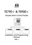
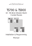
TS700
Intruder Alarm Control Panel
OPEN
_
_
~
OPEN ~
A
1
2
B
4
5
C
7
8
9
D
ENT
0
ESC
_
~
3
6
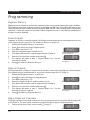
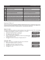
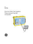
Sett ing the Syst em
Ent er your pa ss code XXXX
th en lea v e th e pro tec t ed a re a.
Unsetting the System
Go dir e ct ly to t he ke yp ad and
en ter you r p as scod e XXXX .
Resetting
Ent er your pa ss code XXXX f ollow ed
by EN T the n 3. Te leph on e you r a lar m
com pan y and follow th eir instr uct io ns.
!
See U ser Manual
A
Part Set
B
1
2
BELL TEST
WALK TEST
4
3
RESET
5
6
CHIME
24 Hr OMIT
C
7
8
9
Part Set
ZONE OMIT
SILENT
D
ENT
Part Set
NEW CODE
0
ESC
FULL SET
Installation & Programming
Instructions
Contents
Overview
Introduction . . . . . . . . . . . . . . . . . . . . . . . . . 3
Control Panel . . . . . . . . . . . . . . . . . . . . . . . . 3
Remote Keypads and LECs . . . . . . . . . . . . . 3
Options . . . . . . . . . . . . . . . . . . . . . . . . . . . . 3
Specifications . . . . . . . . . . . . . . . . . . . . . . . 4
System Configuration. . . . . . . . . . . . . . . . . . 4
Change Engineer's Passcode . . . . . . . . . . 23
Configure Chime Circuits. . . . . . . . . . . . . . 23
Configure 24 Hour Omit Group . . . . . . . . . 23
Print System Log . . . . . . . . . . . . . . . . . . . . . 24
Configure Part-Set Groups . . . . . . . . . . . . . 24
View System Log . . . . . . . . . . . . . . . . . . . . 24
Reset Master User 1 . . . . . . . . . . . . . . . . . . 24
System Installation
Appendices
Cable Routing . . . . . . . . . . . . . . . . . . . . . . . 5
Installing The Control Panel . . . . . . . . . . . . . 5
Mains Connections . . . . . . . . . . . . . . . . . . . 5
..................................5
PCB Layout. . . . . . . . . . . . . . . . . . . . . . . . . . 6
Wiring Detection Circuits . . . . . . . . . . . . . . . 7
Installing Remote Keypads and LECs. . . . . . 8
Engineer's Keypad . . . . . . . . . . . . . . . . . . . . 8
Installing a Plug-on Digicom . . . . . . . . . . . 10
Installing a stand-alone Digicom or RedCARE
. . . . . . . . . . . . . . . . . . . . . . . . . . . . . . . . . 10
Sounder Connections . . . . . . . . . . . . . . . . 11
Installing Output Modules. . . . . . . . . . . . . . 12
Connecting a Printer . . . . . . . . . . . . . . . . . 12
Programmable Outputs . . . . . . . . . . . . . . . 13
Pre Power-Up Checks . . . . . . . . . . . . . . . . . 14
Initial Power-Up. . . . . . . . . . . . . . . . . . . . . . 14
Power-Up Checks. . . . . . . . . . . . . . . . . . . . 14
Factory Default Parameters . . . . . . . . . . . . 15
Programming
Engineer Menu 1 . . . . . . . . . . . . . . . . . . . . 16
Panel Outputs . . . . . . . . . . . . . . . . . . . . . . 16
Digicom Outputs . . . . . . . . . . . . . . . . . . . . 16
Plug-on Digicom Channels . . . . . . . . . . . . 16
Detection Circuits and Attributes . . . . . . . . 18
System Timers. . . . . . . . . . . . . . . . . . . . . . . 19
Setting Modes . . . . . . . . . . . . . . . . . . . . . . 20
System Print . . . . . . . . . . . . . . . . . . . . . . . . 21
Remote Reset Algorithm . . . . . . . . . . . . . . 21
System Configuration. . . . . . . . . . . . . . . . . 21
Engineer's Menu 2 . . . . . . . . . . . . . . . . . . . 22
View Circuits. . . . . . . . . . . . . . . . . . . . . . . . 22
Change Time. . . . . . . . . . . . . . . . . . . . . . . 22
Change Date . . . . . . . . . . . . . . . . . . . . . . 23
2
Domestic Part-Set Application Example. . . 26
Programming procedure . . . . . . . . . . . . . . 27
Commercial Part-Set Application Example 27
Programming procedure . . . . . . . . . . . . . . 29
Installation Record
TS700 Installation Manual
Overview
Overview
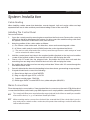
Introduction
The TS700 intruder alarm control system is provided for domestic and commercial intruder alarm
systems conforming to BS4737: part 1: 1986. The system consists of a control panel and at least
one remote keypad.
Control Panel
The control panel is the controlling unit for the alarm system with its own power supply and an
internal battery (supplied separately) for use during a mains failure.
It has the following facilities:
●
Eight programmable detection circuits
●
Bell and strobe output
●
Four programmable high current outputs
●
Eight programmable digicom output
●
Connection for a plug-on digicom
●
Extension loudspeaker output (16 Ohms)
●
1.5 Amp power supply
●
All system data stored in a Non-Volatile Memory (NVM)
Remote Keypads and LECs
The TS700 system will accept three types of remote keypads: The NETLED remote keypad has a 4 x
7 segment LED display and a power indicator. The NETSTAR remote keypad has a 8 character LCD
display and a power indicator. The NETARM remote arming keypad has a power indicator and a
programmable function LED. The Local Expansion Card (TS700.LEC) provides the means of
adding two detection circuits without the need of using a remote keypad. All device types can be
used on the same system, providing the total does not exceed four. Each device provides the
following facilities:
●
Two programmable detection circuits
●
A programmable output
Options
Additional equipment may be connected to the TS700:
●
A plug-on digital communicator type DC54 or DC58 can be fitted inside the control panel to
transfer panel status information to a dedicated alarm receiving centre via the BT network.
●
Other types of digital communicators, RedCARE STU or Paknet interface card can be
connected to the control panel to transfer panel status information to a dedicated alarm
receiving centre via the BT network.
3
Overview
TS700 Installation Manual
●
A printer type CPA6.P (obsolete) or a standard RS232 serial printer via a Menvier Printer
Adaptor (MPA/DCI) can be connected to provide a printout of the 200 log events and system
parameters.
●
An output module type CPA6.OM can be connected to provide an output to a set of
LEDs/relays to indicate circuit activation. Each module will provide up to eight circuit
indications and two modules can be "daisy chained" to provide up to sixteen outputs.
Specifications
Input Voltage:
240V +/-10% 50Hz
Control Panel:
110mA (normal) 190mA (alarm with extension speaker)
Power Supply Rating:
1.5 Amp
NETSTAR Remote Keypad:
50mA (normal) 60mA (alarm)
NETLED Remote Keypad:
60mA (normal) 70mA (alarm)
NETARM Arming Keypad:
30mA (normal) 40mA (alarm)
Battery:
12V 7Ah Sealed Lead Acid type
Zones with tamper loops:
10 - 16
Panel dimensions:
383w x 312h x 95d mm
Panel weight (w/o battery):
4.4kg
Remote Keypad dimensions:
150w x 100h x 30d mm
Remote Keypad weight:
280g
Environment:
0 - 55 °C
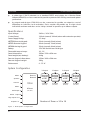
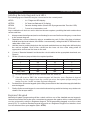
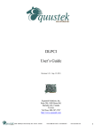
System Configuration
Printer
Speaker
Aux 12V
Remote
Network
TS700
1 Output
1 Output
1 Output
1 Output
Remote
Keypad
or LEC
Remote
Keypad
or LEC
Remote
Keypad
or LEC
Remote
Keypad
or LEC
2 Zones
2 Zones
2 Zones
2 Zones
(DP / EOL)
(DP / EOL)
(DP / EOL)
Printer
Bell output
8 Zones
(DP / EOL)
Strobe output
Digi outputs 1- 8
Outputs 1- 4
Figure 1. TS700 System Configuration
4
Number of Zones =10 to 16
(DP / EOL)
TS700 Installation Manual
System Installation
System Installation
Cable Routing
When installing cables ensure that detection, remote keypad, bell and mains cables are kept
separated from each other and that panel internal wiring is clear of the main PCB.
Installing The Control Panel
Proceed as follows:
1.
2.
Open the control panel by removing two screws from the front cover. Remove the cover by
sliding it up slightly to disengage the bottom clip, disconnect the earth bonding cable from
the spade connection on the front cover, then lift clear.
Note the position of the cable entries as follows:
(a) Ten 20mm cable entries and for detection, alarm and remote keypad cables.
(b) A 20mm cable entry for mains (240V) below the mains input terminal block.
☞ The mains cable must enter the control panel through its own cable entry and must
not be mixed with other cables.
3.
Hold the control panel back box in the required position (keyhole to the top) and mark the
centre of the keyhole position. Remove the back box, drill and plug the hole.
4.
Screw a No 10 screw into the plugged hole. Re-position the back box and mark the
remaining four securing holes. Remove the back box, drill and plug the holes.
5.
Re-position the back box and secure using not less than 30mm x No 10 screws through the
four dished 5mm holes.
6.
Pass all cables into the base via the trunking holes or knockouts, grommeting as appropriate.
7.
If required install and connect the following:(a) Stand alone digicom or RedCARE STU.
(b) Plug-on digicom type DC54, or DC58.
(c) Output modules type CPA6.OM.
(d) Printer type DATAC or serial RS232 via a printer adapter (MPA/DCI).
Mains Connections
The mains supply is connected to a 3 way terminal block connector on the main PCB. All electrical
connections must be carried out by a qualified person and comply with the current IEE regulations.
+
+
To comply with European regulations the supply should be fed from a readily accessible
disconnect device, e. g. un-switched fused spur fitted.
When making mains connections it should be ensured that if the cable slips in such a
way as to place a strain on the conductors, the protective earthing conductor will be the
last to take the strain.
5
System Installation
TS700 Installation Manual
AUX +4 +3 -2 -1
PRINTER
4 5 6 7
3
2
1
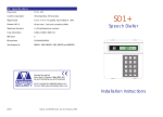
Digicom Outputs
Programmable @ 100mA
LINE DC
FLT PWR
+
T5
Z5
CIRCUIT 5
AUX BELL
T4
Z4
CIRCUIT 4
Z6
T6
CIRCUIT 5
Z7
T7
CIRCUIT 5
Z8
T8
CIRCUIT 5
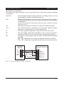
Figure 2. TS700 Main PCB Layout
TRG STB TR- H/O H/O SPK AUX
TAMP
+
+
-
T3
Z3
CIRCUIT 3
BATTERY
FAULT
LED
V
POWER
ON
1 AMP 1 AMP
T2
Z2
CIRCUIT 2
SPKR
VOL
NVM
6
Auxiliary 12V
Auxiliary Tamper
Extension loudspeaker
External sounder
connections
Bell fuse (1A)
Aux. fuse (1A)
N
T1
Z1
CIRCUIT 1
RR
DIGITAL COMMUNICATOR
DIGI-MODEM
JP5
Programmable
Detection
Circuits 1 - 8
Panel Outputs
O/P -1 = Switched -ve @ 500mA
O/P -2 = Switched -ve @ 500mA
O/P +3 = Switched +ve @ 500mA
O/P +4 = Switched +ve @ 500mA
8
JP3
E L
A B C D E
FACTORY
RESET
REMOTE
KEYPAD
1 AMP
JP4
JP2
AUX
0V 12V REMOTE NETWORK
Remote
keypad
Network
connections
ENGINEERS
REMOTE
JP4
0V 12V
OUTPUT MODULE
OUTPUTS
PCB Layout
Mains connection
Mains fuse (200mA)
TS700 Installation Manual
System Installation
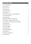
Wiring Detection Circuits
All detection circuits may be wired as "End of line" (EOL) or "Double Pole" (DP). Both methods can be
used on the same system.
Double Pole (DP)
The DP method requires the following:
●
The detector alarm and tamper contacts are connected to the zone and tamper terminals
respectively.
●
The combined alarm and tamper loop resistance must be less than 100 Ohms.
●
The maximum number of detection devices allowed in a circuit is ten.
●
Normally open devices such as pressure pads and exit terminator buttons are connected
between the zone and tamper terminals.
●
If the detection circuit is not used links can be fitted across the zone and tamper loops or
programmed as Not Used.
End Of Line (EOL)
The EOL method requires the following:
●
The detector alarm contacts must have a 4K7 shunt resistor fitted.
●
A 2K2 End of Line (EOL) resistor must be fitted at the point in the circuit furthest from the control
panel.
●
Loop resistance with the EOL resistor shorted must be less than 100 Ohms.
●
The maximum number of detection devices allowed in a circuit is ten.
●
Normally open devices such as pressure pads and exit terminator buttons are connected
across outer terminals
●
If the detection circuit is not used links can be fitted across the zone and tamper loops or
programmed as Not Used.
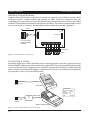
500 meters or 100 Ohms
4K7 = Yellow, Violet, Red
2K2 = Red, Red, Red
ZB
TB
Tamper
Tamper
4K7
ZB
Alarm
TB
Alarm
2K2
Alarm
Alarm
Tamper
Tamper
2K2
CIRCUIT B
ZB
Wiring N.O. devices (Exit Terminators)
4K7
Max. 10 devices per circuit
TB
CIRCUIT A
ZA
Max. 10 devices per circuit
TA
Tamper
Tamper
CIRCUIT B
ZA
CIRCUIT A
TA
ZA
CIRCUIT A
TA
Alarm
4K7
Alarm
CIRCUIT B
500 meters or 100 Ohms
2K2
Wiring N.O. devices (Exit Terminators)
Figure 3. DP and EOL Circuit Connections
7
System Installation
TS700 Installation Manual
Installing Remote Keypads and LECs
The following types of devices may be connected to the control panel:
NETLED
-
4 x 7 Segment LED display.
NETSTAR
-
8 Character Starburst LCD display.
NETARM
-
Remote Arming station (Power LED & programmable "Function" LED).
TS700.LEC
-
2 zone local expansion card.
Any combination of devices can be used on the same system, providing the total number does
not exceed four.
1.
Always ensure that all power (mains and battery) is removed before making any connections
to the remote keypad.
2.
Separate the cover and base by using a screwdriver to push 2 of the clips (top or bottom)
inward from the base indents, then lift the cover assembly, noting that the PCB is fixed to the
under side of the cover.
3.
Hold the base in position (keyhole to the top) and mark the three securing holes, drill and plug
the wall as required. Pass all the cables into the base via the cable entry points as
appropriate and secure the base to the wall.
4.
Connect “Remote Network” and detection circuit cables to the appropriate terminals, see
Figure 4.
5.
Set the I/D selector jumper link to the required position:
I/D Selector
1
2
3
4
ENG / NULL
Circuit A
09
11
13
15
N/A
Circuit B
10
12
14
16
N/A
Panel Output
5
6
7
8
N/A
☞ No two remote keypads or LECs should have the same I/D.
☞ If the I/D is set to “ENG” the remote keypad will function as an Engineer’s keypad
allowing it to be plugged onto the control panel so that system programming and
testing may be carried out (see Engineer’s Keypad).
6.
For details on all remote keypad option links, please refer to the instructions supplied with the
remote keypad.
7.
Finally clip the remote keypad cover onto the base being careful not to trap any cables or to
obstruct the tamper switch.
Engineer's Keypad
Normally all system programming will be carried out from one of the installed remote keypads.
However sometimes it may be more convenient to program the system at the control panel, this
can be achieved by using an Engineers Keypad. This is temporarily plugged on to the control
panel (JP2). To convert a standard remote keypad to an "Engineers Keypad" an interface lead
can be obtained from your supplier (P/No. NETEKI).
8
TS700 Installation Manual
System Installation
100m (Max.)
Spare Core
I/D=1
I/D=2
I/D=3
I/D=4
Remote
Keypad
or LEC
Remote
Keypad
or LEC
Remote
Keypad
or LEC
Remote
Keypad
or LEC
A B CD E
Control Panel
A B CD E
A B CD E
A B CD E
A
Remote B
Network C
D
E
+
Power for
detectors
+
Power for
detectors
+
Power for
detectors
+
Power for
detectors
Figure 4. Remote Keypad & LEC connections
NETARM / NETLED Remote Keypad
NETSTAR Remote Keypad
LED MIMIC
Display Module
Display Module
TB
WARD SOUNDER
CONTROL
CCT A
2 Detection
Circuits
REMOTE
I/D
A B C D E O/P
-
A B C D E O/P
ENT KEY
DISABLED
1
2
3
4
ENG
I/D
Selector
TA
ZB
CCT B
CCT B
ZB
2 Detection
Circuits
1
2
3
4
ENG
REMOTE
I/D
WARD SOUNDER
CONTROL
TA
I/D
Selector
TB
CCT A
ZA
ZA
LED MIMIC
ENT KEY
DISABLED
Remote network
connections
Programmable output
switched -ve
@100mA
Remote network
connections
Programmable output
switched -ve
@100mA
Figure 5 NETARM, NETLED & NETSTAR Remote Keypads
9
System Installation
TS700 Installation Manual
Installing a Plug-on Digicom
1.
A digicom type DC54 or DC58 can be fitted in the base of the TS700 main panel. The unit
should be fitted in accordance with the installation instructions supplied with it and
connected to JP3.
2.
The alarm channels for the plug-on digicom are programmed as required (page 16). It will
be necessary to fit a programmed NVM in the digicom or to program it in accordance with
the instructions supplied with the unit.
Installing a stand-alone Digicom or RedCARE
A stand-alone digital communicator, Red CARE STU or Paknet interface card can be connected
to the system to transfer panel alarm status information to a dedicated alarm receiving centre. The
control panel has the following connections (Figure 6) for a digicom etc.
1 to 8
-
These are the programmable digicom outputs. They are normally at +12V
and switch to 0V when active.
+DC POWER
-
This provides a permanent +12V power to the digicom. The output is
un-fused and therefore should only be used if the digicom is fitted inside
the control panel.
LINE FLT
-
When this input is switched to +12V a telephone line fault condition will be
generated.
REM RESET
-
If the system is programmed for “Engineer Reset”, then after a full alarm the
system will require resetting, normally this is done by the engineer or coded
remote reset. Applying a -ve to this input terminal will cause the system to
reset after a full alarm. This input could be connected to the “Control”
output on a RedCARE STU so that the Alarm Receiving Centre can poll the
STU and thus reset the panel.
Control
TB4
Line
Fault
RPS
10
TB3
Figure 6. 3GSTU RedCARE Connections
Channel Inputs are
Programmed as
Positive Removed
TB2
AUX 0V
3GSTU
TB1
8
7
6
Program
As:5
Open (08) 4
Alarm (05) 3
PA (06)
2
Fire (07)
1
+DC POWER
LINE FLT
1 2 3 4 5 6 7 8 A+ A+ A+ A+ V+ 0V NO C NC NO C NC NO C NC
Control
Panel
TS700 Installation Manual
System Installation
Sounder Connections
The external and internal sounder can be connected to the control panel using the following
connections:
AUX TAMP
-
These terminals provide tamper protection to auxiliary devices such as
power supplies, extension loudspeaker units etc.
SPK+
-
Extension loudspeakers may be connected between [SPK+] and [H/O-].
The minimum impedance is 16 Ohms. Up to two may be connected to the
control panel.
Do NOT run extension loudspeakers within the same cabling as remote
keypads or LECs.
H/O -
-
This is used to provide a permanent -ve hold off to external sounders.
H/O +
-
This is used to provide a permanent +ve hold off to external sounders,
strobes etc. It is protected by a 1 Amp fuse (Bell 12V).
TR -
-
This is the negative tamper return connection from the siren or bell.
STB -
-
This is the strobe output which will switch to 0V on alarm and draws a
maximum of 500mA. Connect the other side of the strobe to the [H/O+].
TRG -
-
This output can be programmed to be either an SAB or SCB and operates
as follows:
SAB: TRG - will switch to 0V on alarm and will sink a maximum of 500mA.
SCB: TRG - will provide a negative hold off, which is removed on alarm.
Control
Panel
H/O H/O +
TR STB TRG -
Typical
External Sounder
0V
+12V
Tamper In
Tamper Out
Strobe +ve
Strobe -ve
Trigger -ve
Figure 7. External and Internal Sounder Connections
11
System Installation
TS700 Installation Manual
Installing Output Modules
Output modules (CPA6.OM) can be used to provide an output to a set of LEDs to indicate circuit
activations (mimic). Output modules will normally be fitted inside the equipment they are
controlling and can be positioned up to 500 metres away from the main panel. They may be fitted
inside the TS700 by fitting posts and securing them to the base. The output module should be used
and connected in accordance with the output module instructions provided (Figure 8).
100m
PL2
PL1
1 2 3 4
+12V OUT
+12V IN
Connect to plug
labelled OUTPUT
MODULE
+12V OUT
To next OM
5 6 7 8
1k Resistors
LED's
Figure 8. Output Module Connections
Connecting a Printer
The printer model type CPA6.P (obsolete) may be directly plugged on to the control panel plug
labelled PRINTER. Alternatively other models such as the DATAC or any standard RS232 serial printer
can be connected to the control panel via a MPA/DCI. Menvier Security supply a DATAC printer kit
which consists of a portable RS323 printer, charger and DCI. The DCI can be purchased separately
if you require to source your own RS232 printer.
POW
ER
PAPER
FEED
IN
DATA
Connect to JP1
PRINTER
P
CPA6
CPA6 Printer
MPA
or DCI
RS232 Data
1
Connect to JP1
PRINTER
DATAC or RS232 printer
Figure 9. Datac Printer Set-up and Connections
12
PRINTER SETUP
Baud Rate = 4800
Parity
= None
Stop Bits = 2
Data Bits = 8
DTR
= Normal
TS700 Installation Manual
System Installation
Programmable Outputs
The TS700 has many programmable outputs which can be used to drive relays, LED’s etc. Each
output can be programmed for a different function, see "Programmable Output Types" on page
17.
Control Panel Outputs
The control panel has four high current programmable outputs:
[-1]
-
Set of voltage free changeover contacts rated at 1 Amp.
[-2]
-
Switched -ve output rated at 500mA.
[+3]
-
Switched +ve output rated at 500mA.
[+4]
-
Switched +ve output rated at 500mA.
Remote keypads & LEC Outputs
Each remote keypad and TS700 LEC has one programmable output:
[O/P]
-
Switched -ve output rated at 100mA.
+ve O/P
(Programmed as Alarm / Bell / etc)
Diode (IN418)
Relay
Aux 0V
+ 12 V
Relay available from
RS components
P/No. 346-946.
Capable of switching
mains voltages
Aux 12 V
Diode (IN418)
Relay
-ve O/P
(Programmed as Alarm / Bell / etc)
+ 12 V
0V
+ve O/P
Relay available from
RS components
P/No. 346-946.
Capable of switching
mains voltages
0V
Aux 12V
(Programmed as Detector Reset)
Aux 0V
Smoke
Detector
Smoke
Detector
-Ve O/P
(Programmed as Detector Reset)
+ve O/P
Aux 12V
1K0 Ohm Resistor
1K0 Ohm Resistor
LED (Light Emiting Diode)
Aux 0V
LED (Light Emiting Diode)
-Ve O/P
+ve O/P
Aux 12V
12V Buzzer
RS Part No. 245-051
Aux 0V
12V Buzzer
RS Part No. 245-051
-Ve O/P
+ve Outputs
-ve Outputs
Figure 10. Programmable Outputs Wiring Examples
13
System Installation
TS700 Installation Manual
Pre Power-Up Checks
Once the system is installed, but prior to powering-up give the system one final check to ensure
that:
1.
The wiring conforms to the requirements detailed in this manual and that all interconnections
are correct (A to A, B to B etc.).
2.
All system cables are kept clear of mains supply cables, telephone cables and R.F. cables. It
is recommended that cable ties be used to keep cables separated.
3.
Verify that maximum cable lengths and resistances are not exceeded.
4.
Mains power supply cables to the system are connected to an un-switched fused spur.
5.
Grommets are used where cables enter metal housings to ensure that insulation is not
compromised.
Initial Power-Up
To power the system for the first time:
1.
Place a small screwdriver blade between the pins on the control panel PCB, marked
"FACTORY RESET". This will ensure the factory default parameters are set (see Table 1).
2.
Switch on the 240V mains supply and remove screwdriver blade.
3.
Check that power LED on the control panel PCB is illuminated.
4.
Check that the remote keypads display "LT" (Panel Lid tamper). The remote keypad
sounders and extension loudspeakers will operate.
5.
Enter the engineers passcode (default 1234) to silence the sounders.
6.
Connect the standby battery.
Power-Up Checks
When the initial power-up checks have been completed, check the following:
1.
Using a voltmeter measure the DC voltage at each remote keypad and ensure the voltage is
greater than 11V whilst running on the system standby battery.
2.
Using a voltmeter measure the DC voltage between mains earth and +12V, and the voltage
between mains earth and 0V. In both cases the measurement should be 1V or less. If the
Voltage is greater than 1V, the system has an "Earth Fault" and all cables should be checked
for isolation to earth.
3.
Using a voltmeter set to a low DC voltage range, measure the voltage across the control
panel PCB test point (V). To calculate the system current consumption multiply the reading by
ten, e.g., a reading of 70mV = 700mA. Ensure that the reading is not greater than 1.0A.
4.
Repeat test (3) with the system in an alarm condition and ensure that the reading is not
greater than 1.0A.
5.
The system is now ready to be programmed see "Programming".
14
TS700 Installation Manual
System Installation
Factory Default Parameters
Engineer's code
1234
Master User
code
5678
1
2
3
4
5
6
7
8
Panel and
Walk Test Courtesy Switched Detector
Code
Code
Code
Code
Remote Outputs
Light
12V
Reset
Accepte Accepte Accepte Accepte
d
d
d
d
Digicom Outputs
& Channels
Detection
Circuits
System Timers
Setting Modes
1
2
3
4
5
6
7
8
Fire
PA
Alarm
Set
Eng on
Site
Bell On
Tamper
Second
Alarm
01: Final Exit
02: Night (access)
03-06: Night
07: Exit Terminator
08: PA Audible
09: Final Exit
10: PA Audible
11-16:Not Used
0
1
2
3
ACPO Delay
0 seconds
No Re-arms
0
Settling Time
07 seconds
Digicom Delay
0 Seconds
4
5
6
7
Exit Time
30 Seconds
Entry Time
30 Seconds
Bell Duration
20 Minutes
Bell Delay
0 Minutes
Part Set B
Timed Exit
Part Set C
Timed Exit
8
9
Double Knock
0 Seconds
Test Time
14 Days
Full Set
Final Exit
Part Set A
Timed Exit
0
1
2
3
Bell output is SAB
User 1 has access
to all user menus
Fire signalled at all
times
24 Hour circuits are
audible
6
7
Reset Algorithm
System
Configuration
004
4
5
bell is delayed for
30 seconds in part
set
Alarm output is
cleared on reset
8
9
Continuous entry
and exit tones
Engineer code only
for access to
engineer menus
Setting with line fault System reset by user
or mains failure is
allowed
Table 1. Factory Default Parameters
15
Programming
TS700 Installation Manual
Programming
Engineer Menu 1
Engineers menu 1 is selected when the engineer's passcode is entered during the unset condition.
The engineer may leave engineer menu 1 by pressing the [ESC] key. The system will return to the
unset condition but the remote keypads will show: "ENG ON SITE". This message will be cleared the
next time a valid user passcode is entered. When engineers mode is selected the monitoring of
tamper circuits is disabled.
Panel Outputs
Outputs 1 to 4 for the control panel and 5 to 8 for the remote keypads can be programmed to any
of the output function types 0 to 55 as listed in Table 2 on page 15.
1. Ensure that "Engineer Menu 1" is selected.
2. Press 1 to select the Panel Outputs option.
3. The display will show: PAN.4. Enter the required output number 1 to 8.
Enter panel output 1 - 4 or
remote output 5 - 6.
5. The display will show the current output function (Table 2).
PAN.-
6.
7.
8.
Enter the new function number and press [.
The display will return to step 3. Repeat steps 4 to 7 for the
remaining outputs.
Press ] to return to "Engineer Menu 1".
04
Enter new output type 00 - 55
(see Table 2.)
Digicom Outputs
The eight switched -ve Digicom outputs 1 to 8 may be connected to the Digicom channel inputs.
The outputs may be programmed to any of the function types 0 to 55 (Table 2).
1. Ensure that "Engineer Menu 1" is selected.
2. Press 2 to select the Digicom Outputs option.
3. The display will show: DIG.4. Enter the required digicom output number 1 to 8.
Enter digicom output 1 - 8.
5. The display will show the current output function (Table 2).
6. Enter the new function number and press [.
7. The display will return to step 3. Repeat steps 4 to 7 for the Enter new output type 00 - 55
remaining digicom outputs.
(see Table 2.)
8. Press ] to return to "Engineer Menu 1".
DIG.04
Plug-on Digicom Channels
The eight channels for the plug-on digicom may be programmed to any of the function types 00
to 55 (Table 2). The procedure is similar to programming the digicom outputs (above).
1.
Follow above procedure, except press 3 at step 2.
Dc3.Enter digicom output 1 - 8.
16
TS700 Installation Manual
No
Programming
Type
Function
00
Bell On
Active when the external Bell trigger is activated.
01
Strobe
Active when the Strobe trigger is activated.
02
SW12
Used to latch devices in an alarm. Active when the system is set.
03
Detector Reset
Used to power devices which require power to be removed to reset them.
04
Walk Test
Active when a Walk Test is in progress.
05
Alarm
Active when intruder alarm is present.
06
PA
Active when a PA alarm is present.
07
Fire
Active when a Fire alarm is present.
08
Set
Active when the system is Set.
09
Code Accepted Active for 10 seconds when any valid passcode is entered.
10
24 Hour
Active when a 24 hour circuit is in alarm.
11
Second Alarm
Active when a second circuit causes an alarm, use for ALARM CONFIRMATION.
12
Courtesy Light
Active when any keypad is in use.
13
Engr on Site
Active when the engineer's passcode is entered until a User passcode is entered.
14
Ccts Omitted
Active when circuits are omitted.
15
Auxiliary
Active when an Auxiliary circuit is in alarm.
16
Sndr Control
Can be used as the 0V connection to an extension loudspeaker so that the
sounder is muted during keypad entries. Only suitable for panel outputs 1 & 2.
17
Area Set A
Active when area A is Set.
18
Area Set B
Active when area B is Set.
19
Area Set C
Active when area C is Set.
20
Tamper
Active when a Aux, or circuit tamper is triggered.
21
Line Fault
Active when a digicom telephone line fault occurs.
22
Mains Off
Active when mains power is removed.
23
Exit/Entry
Active during exit and entry.
24
Test Fail
Active when a circuit on Test is activated.
25
First Knock
Active when a double knock is activated for the first time.
26
DC Failed
Active if the digicom fails to communicate.(plug-on)
27
DC Successful
Active when the digicom sends a message and it is acknowledged. (plug_on)
28
DC Active
Active while the digicom is triggered.(plug-on)
29
Second Entry
Active when the second entry timer is started.
30
Entry
Active when the system is set or part set and the entry route is in use.
31
Exit
Active when the system exit procedure is started.
32
Part Set C fail
Active when Part Set area C fails to set.
33
Part Set B fail
Active when Part Set area B fails to set.
34
Part Set A fail
Active when Part Set area A fails to set.
35
Part Set
Active when ever the system is Part Set.
36
Area C Alarm
Active when Area C Alarms.
37
Area B Alarm
Active when Area B Alarms.
38
Area A Alarm
Active when Area A Alarms.
39
Duress Alarm
Active when a duress code is entered at a keypad.
40- 55 Circuit mimic
Will mimic (active when circuit is active) circuits 1 to 16 respectively .
Table 2. Programmable Output Functions
17
Programming
TS700 Installation Manual
Detection Circuits and Attributes
Detection circuits 1 to 8 for the panel and 9 to 16 for the remote keypads/ LECs are programmed
as follows:
1.
2.
3.
4.
5.
6.
7.
Key
Ensure that "Engineer Menu 1" is selected.
Press 4 to select the Circuits and Attributes option.
Select circuit number (01 - 16) and press [. The current circuit
type will be displayed.
Enter the new circuit type, using keys 0 to 9, or A, B or C (Table 3).
Press [ to accept.
The circuit number, type and attributes are displayed in turn.
Select new attributes by using keys 1 to 5 (Table 4) these will
"toggle" the attributes on & off. Press [ to accept.
Continue for remaining circuits with steps 3 to 5.
Display
CT.-Enter circuit number 01 - 16.
NITE
Enter new circuit type 0 - 9 or A,
B or C (see Table 3.)
Acc
Press 0 - 5 to `toggle' circuit
attributes on & off (see Table 4.)
Circuit Type
0
NoTU
Not Used - A circuits that is not monitored.
1
NITE
Night - A circuit that will generate a full alarm when the system is set.
2
24HR
24 Hour - A circuit which is monitored at all times. When activated in the unset condition a
local alarm is generated and when activated in the set condition a full alarm is generated.
3
PA S
PA Silent - A circuit which is monitored at all times. When activated it will signal a P.A. on the
Digicom outputs and activate any other outputs that have been programmed as P.A.
4
PA A
PA Audible - A circuit which is monitored at all times. When activated it will signal a P.A. on
the digicom outputs, activate any other outputs that have been programmed as P.A. and
generate a full alarm condition.
5
FIRE
Fire - A circuit that is normally connected to a smoke or heat detector. When activated it
will generate a fire tone on internal sounders and the external sounders are pulsed.
6
Au
Auxiliary - A circuit which is monitored at all times. When activated it will cause any of the
outputs that have been programmed as `Auxiliary' to go active.
7
FE
Final Exit - This must be the last detector or door contact that is activated when leaving or
entering the protected area. When the setting mode for the area is programmed for "Final
Exit" setting, opening and closing of this circuit during the exit procedure will cause the
system or area to set. Once set, activation of this circuit will start the entry timer.
8
ET
Exit Terminator - A circuit that is normally connected to a push button outside the
protected area, which operates as follows:
a) When the setting mode is programmed as "Timed Exit", activation of this circuit will cause
any remaining exit time to be truncated to zero.
b) When the setting mode is programmed as "Exit Terminator", the area will set when the
Final Exit circuit has been operated and the exit terminator button is pressed.
9
FULL
Full Set Keyswitch - A circuit which can be connected to a keyswitch to allow the system to
be full-set (active) and unset (healthy).
A
PSA
Part-Set A Keyswitch - A circuit which can be connected to a keyswitch to allow part-set
group A to be set (active) and unset (healthy).
B
PSB
Part-Set B Keyswitch - A circuit which can be connected to a keyswitch to allow part-set
group B to be set (active) and unset (healthy).
C
PSC
Part-Set C Keyswitch - A circuit which can be connected to a keyswitch to allow part-set
group C to be set (active) and unset (healthy).
Table 3. Circuit Types
18
TS700 Installation Manual
Key
Programming
1
Display
Acc
Attribute Type
2
2AcT
Double Knock - Circuits programmed with this attribute will only cause an alarm if:
a) The circuit is activated twice within the Double Knock window (this time may be set in the
System Timers menu).
b) The circuit remains active for the whole duration of the Double Knock window.
The Double Knock attribute may only be assigned to Night, 24hr and Auxiliary circuit types.
3
TEST
Test - Circuits with this attribute will be disabled from the system for the period set by the
"Test Time" (see System Timers). If the circuit is activated during this period the activation will
be logged and the user is informed of the circuit failure when trying to set the system. The
test fail message may only be cleared with the engineer's passcode. If at the end of the test
period no activations have occurred the circuit is automatically removed from test and
behaves as normal. The test period is initiated by entering the engineer's passcode. The test
attribute may only be assigned to Night, 24hr, PA Silent, PA Audible, Fire and Auxiliary circuit
types.
4
ISOL
Isolate - Circuits with this attribute are allowed to be omitted by the user when setting the
system. The isolate attribute may only be assigned to Night, 24hr and Auxiliary circuit types.
5
RST
Reset - This attribute is normally assigned to a circuit that is connected to a Vibration or
Smoke detector, so that during the "Detector Reset" period the circuit is not monitored. The
Reset attribute may only be assigned to Night, 24hr, Fire and Auxiliary circuit types.
Access - Circuits programmed with this attribute are automatically isolated during the
entry procedure to allow a "walk through" route for the user to access the remote keypad.
When the system is part set activation of a circuit with the "Access" attribute will start the entry
timer. The Access attribute may only be assigned to Night circuit types.
Table 4. Circuit Attributes
System Timers
There are ten separate system timers which are shown in Table 5a and 5b.
1. Ensure that "Engineer Menu 1" is selected.
2. Press 5 to select the System Timers option.
3. The display will show: Tir.Enter timer number 0 - 9. (see
4. Enter the required timer number 0 to 9.
Table 5a & 5b)
5. The display will show the current timer setting.
6. Enter the new timer value and press [.
7. The display will return to step 3. Repeat steps 4 to 7 for the Enter timer value 000 -199. (see
Table 5a & 5b)
remaining outputs.
8. Press ] to return to "Engineer Menu 1".
Tir.-
030
Key
Timer
Range
Function
0
ACPO Delay
0-199 sec For ACPO requirements this timer is normally set to 90 seconds. If during the
entry procedure the user deviates from the entry route and causes an
alarm, the communication of the alarm signal to the central station is
delayed by this timer.
1
Re-Arms
0-199
At the end of the bell duration time the system re-arms all circuits that are
healthy. Circuits that are still in an alarm are isolated until they change to a
healthy condition. This timer controls the number of times that a circuit will
re-arm before it is locked out of the system.
Table 5a. System Timers
19
Programming
TS700 Installation Manual
2
Settling Time
3
Digicom Delay 0-199 sec When the system is part-set the communication of an alarm signal to the
central station may be delayed by the value set in this timer.
4
Exit Time
0-199 sec This timer sets the delay between the user initiating the exit procedure and
the system (or area) actually Setting. If during the exit time an Exit Terminator
circuit is activated the exit time is cancelled and the system sets
immediately.
5
Entry Time
0-199 sec The time allowed for entering the protected premises via the entry route
when the system is (Part) Set . The time is allocated to two entry periods. A
warning is given if the first is exceeded and a full alarm occurs if the second
is exceeded.
6
Bell Duration
0-199 min The duration time of the bell and sounders when an alarm occurs.
7
Bell Delay
0-199 min This timer delays the activation of the bell output and internal sounders.
8
Double Knock
0-199 sec This is the Double Knock time window in which either:
Two circuit activation must occur within this time to generate an alarm
condition. Or the circuit must remain active for the whole duration of this
time to generate an alarm condition. This will only apply to circuits with the
Double Knock attribute
9
Test Time
0-30 days
0-199 sec When setting the system by "Final Exit" or "Exit Terminator", detectors that are
on the exit route sometimes take 3-4 seconds to settle after activation. The
delay programmed in this timer is used to allow these detectors to settle
before the system or area is set.
This timer varies the number of days that Test attribute may be applied to a
circuit. If the time is set to 000 then circuits will remain on test until the "Test"
attribute is removed.
Table 5b. System Timers
Setting Modes
The system may be set by one of the following modes:
Final Exit
-
The system or area will set when the "Final Exit" circuit is activated and after
the "Settle Time" has expired.
Exit Terminator
-
The system or area will set when the "Final Exit" circuit is activated, the "Exit
Terminator" button is pressed and after the "Settle Time" has expired.
Timed Exit
-
The system or area will set when the "Exit Time" has expired or if the "Exit
Terminator" button is pressed.
The
1.
2.
3.
4.
5.
setting mode for full-set, part-set groups A, B and C are programmed as follows:
Ensure that "Engineer Menu 1" is selected.
Press 6 to select the Setting Modes option.
The display will show: S.BYEnter setting group 0,A,B or C.
Select setting group by pressing:
S.BY-
0
for full-set
A
for part-set group A
B
for part-set group B
C for part-set group C
The display will show the current setting mode.
F-FE
Enter setting mode 1,2,3 or 0.
20
TS700 Installation Manual
6.
Programming
Select new setting mode by pressing:
1
for Final Exit
2 for Exit Terminator
3
7.
8.
+
for Timed Exit
0 to `toggle' between all three options
When the display shows the required setting press [ to accept.
The display will return to step 3. Repeat steps 4 to 7 for the
remaining setting groups.
Press ] to return to "Engineer Menu 1".
When using part set codes to set areas, the first area that is set will follow the setting mode
defined by that area. Any subsequent areas will always use the timed exit method.
System Print
A print-out of all system parameters may be obtained so that a permanent record of the system
program details may be kept.
1. Ensure that "Engineer Menu 1" is selected.
2. Press 7 to select the System Print option.
Press ESC to cancel printing.
3. The display will show the line that is being printed (Ln01).
4. Press ] to stop printing and return to "Engineer Menu 1".
Ln01
Remote Reset Algorithm
When the system requires an Engineer Reset this may be over ridden by using the Remote Reset
facility. To provide additional security the way in which the "Reset Code" is generated can be
selected to be one of 199 algorithms (default=004).
1. Ensure that "Engineer Menu 1" is selected.
2. Press 8 to select the Reset Algorithm option.
004
3.
4.
The display will show the current setting.
Enter the new number and press [ to accept.
Enter new number 000 - 199.
System Configuration
There are ten system configuration options which are shown in Table 6.
1. Ensure that "Engineer Menu 1" is selected.
2. Press 9 to select the System Configuration option.
3. The display will show: con.Enter configuration number 0- 9
(see Table 6).
4. Enter the required configuration number 0 to 9.
5. The display will show the current setting. Press 0 to "toggle"
between YES and NO. Press [ to accept.
Press 0 to `toggle' the option
6. The display will return to step 3. Repeat steps 4 to 6 for the between YES or NO.
(see Table 6).
remaining system configuration options.
7. Press ] to return to "Engineer Menu 1".
con.-
YES
21
Programming
Key
TS700 Installation Manual
YES
NO
0
Bell output is set for SAB
1
Disable Master User from menu 2 options 4-9
Master user has access to all options in menu 2
2
Fire Signalled when Unset/Part Set/Full Set
Fire signalled only when full Set
3
24hour circuits silent when Unset
24hour circuits audible when Unset
4
Bell is instant when Part Set
Bell is delayed when Part Set (30 secs)
5
Alarm output (05) cleared when system is unset
Alarm output cleared when system is reset
6
Setting inhibited with line fault/no mains power
Setting allowed with line fault/no mains power
7
System reset by User or Engineer
System reset by Engineer or Remote Reset
8
Continuous Entry and Exit tones
Rising Entry and Exit tones
9
Engr & Remote Reset code to gain access to E1/E2 Engr code gains access to E1 and E2 menus
Bell output is set for SCB
Table 6. System Configuration options
Engineer's Menu 2
This menu is selected by pressing the [ENT] key whilst "Engineers menu 1" is selected. There are ten
programming options within this menu, which can be selected in any order. The engineer can
leave this menu and return to "Engineers Menu 1" by pressing the [ESC] key.
View Circuits
This option allows the engineer to view the status of each detection circuit. The circuit status
conditions are H=Healthy, A=Active, S=Shorted or T=Tamper.
1. Ensure that "Engineer Menu 2" is selected.
2. Press 1 to select the View Circuits option.
Circuit 03 is Healthy.
3. The circuit status will be displayed.
4. Select circuits either by entering the number or by pressing [ to
scroll through the circuits.
Circuit 03 is Active.
5. Press ] to abandon and return to "Engineer Menu 2".
03-H
03-A
Change Time
The system clock may be changed using 24 hour clock format.
1. Ensure that "Engineer Menu 2" is selected.
2.
3.
4.
22
Press 2 to select the Change Time option.
Enter the time in 24 hour notation (e.g., 1805).
Press [ to accept.
---Enter time in 24 hour format.
1805
Time entered 1805 (6:05 pm.)
TS700 Installation Manual
Programming
Change Date
The system calendar may be changed by entering the date as four digits representing the day
and month e.g., 0207 is the 2nd July.
1.
2.
3.
4.
Ensure that "Engineer Menu 2" is selected.
Press 3 to select the Change Date option.
Enter the date as four digits.
Press [ to accept.
----
Enter date (day & month).
0207
Date entered 0207 (02 July).
Change Engineer's Passcode
The factory default engineer's passcode is set to 1234, but the installation engineer should change
this to their own personal four-digit passcode, as follows:
1. Ensure that "Engineer Menu 2" is selected.
2. Press 4 to select the Change Engineer's Passcode option.
Enter new engineer passcode.
3. Enter the new passcode then press [ to accept.
4. A high tone will indicate acceptance. A low tone sound will
indicate that the passcode is not available.
---2804
New passcode 2804 entered.
Press ENT to accept.
Configure Chime Circuits
This option is used to select the circuits that will chime.
1.
2.
3.
4.
Ensure that "Engineer Menu 2" is selected.
Press 5 to select the Chime Circuits option.
Circuits will be displayed as Y(Yes) to chime or N(No) not to
chime. Change status by pressing 0 ("toggle" action).
Press [ to accept (high tone) and go to next circuit. Circuits may
be selected by number. Press ] to quit.
01-N
Circuit 01 will not chime.
Press 0 to change.
01-Y
Circuit 01 will chime.
Press ENT to accept.
Configure 24 Hour Omit Group
This option allows the engineer to select the 24 hour circuits that will be omitted when the 24 hour
omit option is selected in "User Menu 1" option 6.
1. Ensure that "Engineer Menu 2" is selected.
2. Press 6 to select the 24hour Omit Group option.
02-A
3.
4.
5.
Circuits will be displayed as O(Omitted) or A(Armed). Press 0 to
change ("toggle" action).
Press [ to accept (high note) and go to next circuit. A low tone
indicates that the circuit cannot be omitted.
Circuits may be selected by number. Press ] to quit.
Circuit 02 will remain Armed.
Press 0 to change.
02-O
Circuit 02 will be Omitted.
Press ENT to accept.
23
Programming
TS700 Installation Manual
Print System Log
A printer may be connected to produce a print-out of the last 200 system events.
1. Ensure that "Engineer Menu 2" is selected.
2.
3.
4.
Press 7 to select the Print Log option.
Enter the number of events to be printed.
Press [ to start printing. To stop printing select the menu again
and enter 000 as the number of events to be printed.
---
Enter the number of events to
be printed. Press ENT to start.
Configure Part-Set Groups
When the system is part-set certain circuits are omitted. This option allows the engineer to select
those circuits to be omitted when part-set A or B or C is selected.
1. Ensure that "Engineer Menu 2" is selected.
2. Press 8 to select the Part-Set Groups option.
Enter part-set group A, B or C.
3. Select the part-set group A or B or C.
4. Circuits will be displayed as O(Omitted) or A(Armed). Press 0 to
change ("toggle" action).
Circuit 01 will remain Armed.
5. Press [ to accept displayed status (high tone) and go to next Press 0 to change.
circuit. Circuits may be selected by number.
6. Press ] to return to step 3 and ] again to return to "Engineer
Circuit 01 will be Omitted.
Menu 2".
PS -
01-A
01-O
Press ENT to accept.
View System Log
The time, date and nature of the last 200 events on the system may be viewed starting with the
most recent event.
1. Ensure that "Engineer Menu 2" is selected.
2. Press 9 to select the View Log option.
3. The most recent event will be displayed (see Table 7)
4.
5.
Press A to scroll back and C to scroll forward. Press B to show the
time of the event (first press), the date (second press) the time in
minutes and seconds (third press).
Press ] to abandon.
CA.01
Log event showing `Circuit
Alarm 01'. Press A to scroll back
or C to scroll forward. Press B to
view time and date.
Reset Master User 1
This option allows the engineer to reset the master user passcode back to the factory default code
`5678'. This feature is useful when the master user has forgotten their passcode or has inadvertently
changed it.
1. Ensure that "Engineer Menu 2" is selected.
2. Press 0 to Reset User 1.
24
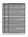
TS700 Installation Manual
Programming
AA
Action Alarm (Alarm output activated)
Ac**
Access Passcode (User code **entered OP
with the last two digits reversed)
System Open (unset)
AD.**
Alarm Delayed (the system is part set and Or
circuit ** was activated)
Omits Removed
Au.**
Auxiliary Alarm
**activated)
(circuit
LT
n u m b e r PA.**
Lid Tamper or SAB tamper
PA Alarm (from circuit number **)
BF
Battery Fault (battery voltage below 10.5V) PF
BT
Bell Test
Pr
Power Restored
CA.**
Circuit Alarm (from circuit number **)
PS.*
Part Set (area *)
Power Failure (remote power LED flashes)
cc
Communication Complete (Plug-on only)
PT.**
Code Tamper (from remote keypad **)
cF
Communication Failed (plug-on only)
rA
System re-armed
CI
Circuits Isolated (24 hour circuits)
rc
System reset by REMOTE CODE RESET
CO.**
C i r c u i t s O m i t t e d ( c i r c u i t n u m b e r rr.**
**omitted)
Remote Keypad ** removed
Dc
Date Changed
rT.**
Remote Keypad ** case tamper
DF
Default User code 1 to 5678
SF
System Failed to Set
Du.**
Duress Alarm (from User code **)
Sr
System on-site reset (LK1 open on power
up)
EA.**
Entry Alarm (from circuit number **)
ST.*
Area * Set (using area setting codes)
En.**
Entry (from circuit number **)
So.**
Part set keyswitch ** operated
FA.**
Fire Alarm (from circuit number **)
TA.**
Tamper Alarm (from circuit number **)
FB.**
Fuse Blown (fuse number **)
Tc
Time Changed
Fn.**
First Knock (from circuit number **)
TF.**
Circuit ** failed test
Fr
Factory Reset (LK1 closed on power up)
To
All Test circuits removed from test
FS
Full Set
Un.*
Area * unset (using area setting codes)
LB
Low Battery
Ur.**
User Code ** entered
LF
Telephone line fault
--
No event
Lr
Telephone line restored
Table 7. Event Log Codes
25
Appendices
TS700 Installation Manual
Appendices
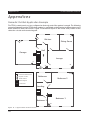
Domestic Part-Set Application Example
The TS700 control panel can be configured so that only part of the system is armed. The following
example illustrates how the TS700 alarm system is configured so that it protects different areas of a
three bedroom detached house. Figure 11 shows the layout of the house and position of the
detection circuits and remote keypad.
P
7
C
Kitchen
6
C
5
Dining Room
Hall
Garage
CP
S
3
Lounge
4
C
RK
2
C
8
P
P
1
Key:
P
Passive Infra-Red Detector
C
Magnetic Contact
S
Smoke detector
9
Bathroom
Bedroom 2
RK Remote Keypad
CP Control Panel
Landing
RK
Bedroom 1
Bedroom 3
P
Figure 11. A typical three bedroom house.
26
10
P
TS700 Installation Manual
Appendices
Using the plan of the typical three bedroom house, the following part-set arrangements are
required by the occupants of the house:
Full Set
-
All circuits to be armed.
Part-set Group A
-
Circuits 9 and 10 to be omitted. This is required for normal night setting
when everyone is in the house and have retired to bed.
Part-set Group B
-
Circuit 10 to be omitted. This is required when the occupant of bedroom 2
is away for the weekend.
Part-set Group C -
Circuits 2, 7, 8, 9 and 10 to be omitted. This is required when only perimeter
protection is required.
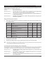
Programming procedure
1.
First create a table listing the circuits that are required to be Armed (A) and Omitted (O) for
each part-set group:
Circuit No.
Location
Group A
Group B
Group C
01
Front Door
A
A
A
02
Hallway Detector
A
A
O
03
Smoke Detector
A
A
A
04
Garage up and over door
A
A
A
05
Garage door (back)
A
A
A
06
Kitchen Door
A
A
A
07
Dining Room PIR
A
A
O
08
Lounge PIR
A
A
O
09
Bedroom 2 PIR
O
A
O
10
Bedroom 1 PIR
O
O
O
2.
From the above table assign circuits 01 - 10 as "Armed" or "Omitted" for each part-set group,
see page 24 for full details.
3.
Program the setting mode for each part-set group, see page 20 for full details..
+
The PIR in the hallway (circuit 02) will need the "Access" attribute so that first person that
comes down the stairs will start the entry timer.
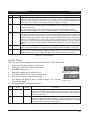
Commercial Part-Set Application Example
This application example demonstrates how to use the "Part-set Codes" to set and unset different
areas within a commercial premises. Using the plan of the building the following is required:
Part-set code A
-
The sales manager will be assigned this passcode to access the sales and
canteen area.
Part-set code B
-
The workshop manager will be assigned this passcode to access the
workshop and canteen area.
Part-set code C
-
The stores manager will be assigned this passcode to access the stores
and canteen area.
27
Appendices
P
TS700 Installation Manual
1
14
CP
Stores
P
RK
13
C 7
C
P
6
Workshop
Canteen
2 C
C 5
3
4
P
C
Sales
Office
11
C
12
RK
P
P
8
10
RK
P
9
C
KEY:
P
C
RK
CP
Passive Infra-Red detector
Magnetic Contact
Remote Keypad
Control Panel
Figure 12. Commercial Premises
The "Part-set Codes" A, B and C only affect the circuits assigned in their respective "Part-set Group'"
i.e., "Part-set Code A" will set and unset the circuits assigned as "Omitted" in "Part-set Group A".
When configuring the TS700 system to use "Part-set Codes", it is important to think of the system
from the full-set state. When a part-set code is entered the circuits that have been assigned as
"Omitted" for that "Part-set Group" will be unset. On re-entry of the "Part-set Code" the exit
procedure is started and at the end of the exit procedure the circuits that were "Omitted" are
armed again.
28
TS700 Installation Manual
Appendices
Programming procedure
1.
First, imagine the system is fully set. When "Part-set Code A" is entered certain circuits are
required to be "Omitted" whilst others remain "Armed". Create a table listing the circuits that
are to be "Omitted" (O) when "Part-set Code A" is entered. The circuits that will not be omitted
must therefore remain "Armed" (A). Then imagine the system is fully set again and repeat for
"Part-set Codes" B and C.
Circuit No.
Location
Group A
Group B
Group C
01
Workshop PIR (1)
A
O
A
02
Workshop Internal Door
A
O
A
03
Workshop PIR (2)
A
O
A
04
Sales Internal Door
O
A
A
05
Canteen Door
O
O
O
06
Canteen PIR
O
O
O
07
Stores Internal Door
A
A
O
08
Sales PIR
O
A
A
09
Sales Office PIR
O
A
A
10
Sales Entrance Door
O
A
A
11
Workshop Entrance Door
A
O
A
12
Workshop PIR (3)
A
O
A
13
Stores Entrance Door
A
A
O
14
Stores PIR
A
A
O
2.
From the above table assign circuits 01 - 14 as "Armed" or "Omitted" for each "Part-set
Group", see page 24 for full details.
3.
Program the setting mode for each "Part-set Group", see page 20 for full details.
4.
Program each "Part-set Code" with a four digit passcode, refer to the "User Operating
Instructions".
+
If a circuit is "Omitted" in more than one "Part-set Group" (circuits 05 and 06 in our example) it
will only be armed when all "Part-set Groups" are set. Using our example, if the system is
unset and "Part-set Code A" is entered, the exit procedure is started and at the end of the
exit procedure circuits 04, 08, 09 and 10 will be armed. The canteen detection circuits 05
and 06 will remain unarmed until "Part-set Group" B and C are set (system full-set).
29
Installation Record
TS700 Installation Manual
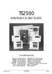
Installation Record
Circuit Programming
No
Location
Type
Access D-Knock Test Omit Reset PS A PS B PSC 24hr
01
02
03
04
05
06
07
08
09
10
11
12
13
14
15
16
Output
1
2
3
Outputs
4
5
6
7
Panel & remotes
Digicom outputs
Digicom Channel
System Timers
Re-arms:
Settling:
Digi Delay:
Exit Time:
Entry Time:
Bell Dur:
Bell Delay:
D-Knock:
Test Time:
ACPO:
Setting Modes
Part-set A
Part-set B
Full-set
Part-set C
System Configuration
1: Yes / No
2: Yes / No
3: Yes / No
4: Yes / No
5: Yes / No
6: Yes / No
7: Yes / No
8: Yes / No
9: Yes / No
0: Yes / No
Other
Algorithm No
Installation Company:
Remote Reset Tel No:
Engineer:
Date:
Tel No:
30
8
SET CLOCK
----
]
ENGINEER MENU 1
E1 -
VIEW CIRCUITS
01-H
0
RESET MASTER
USER
E2 -
.
2
----
ENGINEER
PASSCODE
4
Full Set
Part Set A
Part Set B
Part Set C
01-A
01-N
POWER
CONFIGURE 24 HR
OMIT GROUP
6
7
Press ESC to stop
Ln01.
SYSTEM PRINT
7
PS. -
CONFIGURATION
con.-..
CONFIGURATION
9
Ur.0. 0
VIEW SYSTEM LOG
9
1 Y=User 1 limited in menu 2
N=User 1 not limited in menu 2
2 Y=Fire signalled in unset/partset
N=Fire not signalled in unset/partset
3 Y=24hr ccts silent in unset
N=24hr ccts audible in unset
4 Y=Bell instant in partset
N=Bell delayed in partset
5 Y=Alarm output cleared when unset
N=Alarm output not cleared
6 Y=Setting inhibited with LF/no AC
N=Setting OK with LF/no AC
7 Y=User Reset
N=Engineer Reset
8 Y=Constant Exit tone
N=Rising Exit tone
9 Y=Eng Code + Reset code for access
N=Eng Code for access
0 Y=Bell is an SAB type
N= Bell is an SCB type
CONFIGURE
PART-SET GROUPS
8
Enter number
004 .
ALGORITHM NO
8
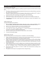
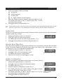
SELECTING USER MENU 1
1. From E1 - press 0.
2. The display will show `1 -'.
3. Refer to `User Operating Instructions' for full details.
---
PRINT SYSTEM LOG
Engineer Menu 2
.
ATTRIBUTES
1 Final Exit
2 Exit Terminator
3 Timed Exit
0 "Toggle"
0
A
B
C
SETTING MODES
S.B. Y-.
SETTING MODES
6
Engineer Menu 1
CONFIGURE CHIME
5
Press key to select option
E2 -.
From E1 - press [
No of Re-Arms
Settling Time
Digicom Delay
Exit Time
Entry Time
Bell Duration
Bell Delay Time
Double Knock Time
Test Time
Acpo Delay Time
TIMER OPTIONS
1
2
3
4
5
6
7
8
9
0
CIRCUIT TYPES
Night
24 hr
P.A. Silent
P.A. Audible
Fire
Aux
Final Exit
Exit Terminator
Full Set Key
Not used
Part Set Key A
Part Set Key B
Part Set Key C
ATTRIBUTES
1 Access
2 Double Knock
3 Test
4 Isolatable
5 Reset
1
2
3
4
5
6
7
8
9
0
A
B
C
Tir.-.
POWER
SYSTEM TIMERS
5
CT.-. -.
PROGRAM
CIRCUITS
4
Press key to select option
E1 -
Enter engineer passcode
(Default 1234)
RETURNING TO UNSET
1. From E1 - press ].
2. The display will show `ENG. ON SITE'.
3. This message is cleared by entering a valid user passcode.
----
SET DATE
3
21 Line Fault
22 AC Off
23 Exit / Entry
24 Test Fail
25 First Knock
26 DC Failed
27 DC Successful
28 DC Active
29 2nd Entry
30 Entry
31 Exit
32 Part Set C fail
33 Part Set B fail
34 Part Set A fail
35 Part set
36 Area C Alarm
37 Area B Alarm
38 Area A Alarm
39 Duress Alarm
40 - 55 Circuit Mimics 1-16
1
Bell On
Strobe
SW12V
Viper Reset
Walk Test
Alarm
P.A.
Fire
Set
Code Valid
24hr
2nd Alarm
Courtesy Light
Eng on Site
Circuits Omitted
Auxiliary
Sounder control
Part Set A
Part Set B
Part Set C
Circuit Tamper
OUPUT TYPES
DIG.-..
PAN.-..
00
01
02
03
04
05
06
07
08
09
10
11
12
13
14
15
16
17
18
19
20
DIGI CHANNELS
DIGI OUTPUTS
PANEL OUPUTS
Dc3.-..
3
2
1
Quick Reference Guide
Menvier Security Ltd.
Kenn Road, Clevedon,
Bristol BS21 6LH, England
Tel: +44 (0)1275 870078
Fax: +44 (0)1275 343453
Email: [email protected]
Internet: http//:www.menviersecurity.co.uk
18606
Drg No. 33:2159:00 Issue 01 Doc. 01 August 98