1
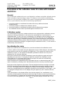
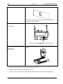
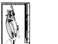
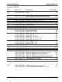
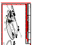
Service Manual
Variants:
for seca 374 / 375 / 376 CN
3741321009
3741321369
3757021009
3767021004
3767021009
3767021094
3767021099
3767021159
3767021249
Service Manual Number:
17-05-01-329-b
Valid as of:
01.03.2008
Description:
electronic babyscale multi load cell design, DMS low end module, LCD, for battery
use, prepared for mains operation.
Content:
Operation mod. 374
17-10-06-301 a
Operation mod. 375/376
17-10-07-496 c
Operation mod. 376 Japan
17-10-07-513 c
Description DMS module
30-34-00-645 b
Description of faults
30-34-00-588 c
Function diagram
25-01-02-560 a
Calibration (lin.)
30-34-00-603
PC configuration program
30-34-00-672 b
Replacement
30-34-00-726
Spare parts
30-34-00-727 b
Manual number:
17-05-01-329-b
Service manual
Description of the electronics
Brief description of the DMS module
Introduction
The DMS modules are used to determine weights using a load cell with strain gauges. The DMS low
end module also accommodates the display and the operating unit. To allow the modules to be
adapted to different scales, an EEPROM is integrated which is used to configure the module. A
connection to the SeSAM bus (Seca’s Serial Autoconfiguring Multicontroller bus) is provided via which
the scale can be calibrated and additional modules can be connected.
Display
Load cell
I 0 0.0 0
A/D Converter
Operation
EEPROM
Voltage
control
Quartz
Temperature
measurement
µC
SeSAM Bus
Power On
Reset
Voltage
measurement
Voltage
control
Mains connection
Battery/rechargeable
batteries
Weight measurement
The DMS modules use load cells with strain gauges in a double bridge circuit as sensors.
The entire analog part runs on its own supply voltage. This voltage can be switched by the µC to 3V,
5V or 10V. This voltage is also supplied to the load cells. At full load, they deliver a bridge output
voltage of 2mV/V.
This voltage is measured by a dual slope a/d converter. The DMS ext module can evaluate up to four
load cells which are multiplexed accordingly. Only one load cell can be connected to the other types of
DMS modules.
The conversion time is selected so that a new measured value is available every 0.1 s.
The resolution of the a/d converter is 0.05 µV/V. If several load cells are connected, keep in mind that
the resolution relates to the mean output signal of all the load cells connected.
When these measured values are within the expected range, they are converted into a weight value
using a third order polynomial. In order to increase accuracy, eight measured values are used to
calculate the weight to be displayed.
The first value obtained after switch-on is used as the zero point. If the values obtained later on do not
deviate strongly from this value, the zero point is corrected in order to compensate for possible drifts.
(Please also refer to temperature measurement.)
05.08.03 /Jensen / Rei
1
34-34-00-645 b
Service manual
Description of the electronics
Display (only DMS low-end module and SLC highend)
Whenever eight new measured values are available, i.e. approx. every 0.8 s, the weight is displayed.
The display is an LCD which is controlled by duplex operation. A maximum of five digits as well as a
few special characters can be displayed.
Explanation of the special characters:
• The battery symbol is used to alert of the fact that the battery is going flat.
• Hold indicates that the weight display has frozen.
• Tare or Net indicate that a weight on the scale has been tared off.
• The left arrow indicates if additional explanations are given next to the display.
• The weight units on the right show the unit in which the measured weight is displayed.
Temperature measurement
In order to compensate for the load cell’s temperature drift, the temperature is measured regularly and
the measured value is adjusted accordingly.
To perform this measurement, a capacitor is charged every 2 seconds alternately via a reference
resistor and an NTC with a linearization resistor connected in parallel. The time until the capacitor has
reached a specific voltage is measured. The temperature is calculated from the ratio of the two times.
To reduce measured value fluctuations, a mean value of 16 temperature values is always formed. The
fluctuation then amounts to approx ±0.2°C.
The difference between the current temperature and the temperature measured when the last zero
point was obtained is used to determine a projected zero point. To do so, one assumes that the weight
change per °C is constant. The weight value is then corrected in accordance with the zero point
calculated and in accordance with the difference to the temperature measured when the scale was
calibrated. A linear and a square term are used for this purpose.
Power supply
Power supply is provided by AA size batteries (batteries or rechargeable batteries) and a plug-in power
supply unit. The batteries pass the voltage via reverse voltage protection diodes to a 3V in-phase
regulator. A coil which suppresses interference and a buffer capacitor come next. This 3 V supply
voltage is supplied to the digital part of the circuit.
Another in-phase regulator generates the voltage for the analog part. The µC can set this regulator to
3V, 5V or 10V.
In order to operate the module on rechargeable batteries a recharging circuit can be connected. This
circuit charges the rechargeable batteries at a constant current when a power supply unit is connected.
When the supply voltage is applied, a power-on reset is initiated at the µC via an RC element.
To monitor the condition of the batteries, their voltage is measured every 2s. For this purpose, a 2.2 V
reference voltage is integrated upwards and the time until the voltage has reached approx. 9% of the
supply voltage is measured. Afterwards, a downwards integration is made from 2.2V to the threshold.
From these two results, a measured value for the voltage is calculated. If the voltage drops below a
certain limit, the user is alerted by the battery symbol in the LCD. If the next threshold is undershot,
„bAtt“ is displayed and weighing is no longer possible.
Operation (only DMS low-end module and SLC highend, with the exception of
vibration-sensitive switch and platform switch)
Four buttons are provided; one is used to switch the module on and off, the others can be programmed
as required. These three buttons can be pressed just lightly or longer (longer than 1.5s), so that six
events are available. The actions tare, hold and unit switch-over can be assigned to them.
If you press another button when switching on the scale, the scale will switch to the calibration counter
and recalibration mode.
Instead of the normal start button a piezo diaphragm can be soldered to the PI connection. If the piezo
diaphragm registers a vibration, a transistor switches and generates an interrupt signal which causes
the µC to start.
05.08.03 /Jensen / Rei
2
34-34-00-645 b
Service manual
Description of the electronics
If the start button is directly connected to this interrupt input, a button is obtained which is only active
when the scale is switched off. It can be fitted under the platform, for instance, so that the scale is
started by briefly stepping on it.
Programming
The DMS modules are equipped with an EEPROM which is controlled via the I²C bus protocol. On this
EEPROM all parameters are stored that can be used to influence the program sequence. For example
the way the weight is displayed or the allocation of buttons. It also stores the coefficients for
determining the weight and data for temperature compensation, e.g. the factors for the polynomial.
Furthermore, the scale can store values to be retrieved when the scale is switched on the next time,
e.g. the weight unit used last.
In order to avoid errors, the EEPROM contents are divided into blocks which are monitored by cyclic
redundancy checks. The hamming distance is 4 so that single errors can be corrected and double
errors are certainly detected. In addition, values which are recalculated when the scale is in operation
can be replaced by default values if an error is detected that cannot be remedied.
Serial bus
To allow the scale to be calibrated and additional modules, such as additional displays, to be
connected, the DMS modules are equipped with an interface to the SeSAM bus.
On this bus the stabilized and non-stabilized supply voltages are available. Via a data and a clock
pulse line all relevant data is transmitted to other modules. A special start line is provided via which the
scale can be switched on or other modules can signal that they want to send data.
Both data and start line are open collectors so that they can be switched to low by all modules.
For further details on the bus, please refer to the relevant documentation.
Fault handling
If faults occur, the SeSAM bus initiates a fault message with the relevant fault code. Furthermore, each
fault message includes the number of the module type on which the fault has occurred and a code
which indicates how long the message is to stay on display and which displays are to be suppressed.
The DMS low end module displays its own fault messages on its LCD. Module type (0 for the low-end
module) and fault number are displayed. The other DMS modules only transfer fault messages to the
bus (module type = 1).
The following fault messages are implemented:
10
11
12
13
14
15
bAtt
21
22
tEMP
30
32
33
40
41
50
51
CArd
OFF
6x
20 bit counter overflow
Counts out off range
Switch-on zero setting out off range
Zero tracking out off range
Error in the kg value calculation
Recalibration error
Battery voltage too low
Error in battery voltage measurement
Error in temperature measurement
Temperature range exceeded ( < 0°C or > 50°C)
General bus error
Command buffer full
More than 8 slaves detected
EEPROM error
Incorrect EEPROM access
Rom checksum error
Menu error
Invalid Chipcard
Chipcard has scale not released
Error in measurement of lenght
Notice : Chipcard is saving now
05.08.03 /Jensen / Rei
3
34-34-00-645 b
Service manual
Description of the electronics
Time base
From the quartz’s 4.19MHz a time base is derived which controls all timed processes in the scale.
These are, for instance, various timeouts and the on-time.
After expiry of the on-time, the supply voltage for the analog part, for voltage measurement and for the
EEPROM is switched off. The LCD is switched off, all ports are set to zero-signal level and the quartz
is stopped.
Recalibration
In order to compensate for linear measuring errors of the scale, which can, for instance, occur as a
result of the different forces of gravity at different geographical points, the module has a recalibration
function. To initiate the function, another button must be pressed when the scale is started. The
calibration counter is now displayed which is incremented whenever the scale is recalibrated. It
enables the user to check whether the scale was manipulated. If, within five seconds, the button is
pressed longer than 1.5 s, the scale switches to recalibration mode. The scale now measures the zero
point and waits to be loaded with at least ¼ of the maximum load. By briefly pressing the button the
weight displayed can be decremented or incremented in steps of 10g until the weight of the load placed
on the scale is reached. The direction can be changed by pressing the button longer. To stop
recalibration the button must be pressed longer than 5s. The scale can be switched off any time using
the on/off button or by not activating it for a while, thus aborting recalibration.
Optional functions (only DMS low-end module and SLC highend)
The functions “Tare“, “Hold“, “Autohold“ and “Replace weight in repeat measurements” can be
implemented via a program on the EEPROM. The functions are explained below:
Tare:
The tare function can be assigned to a button by the EEPROM program. If the button is pressed, the
weight is tared off as soon as the display has settled, if it is within the permissible range. Pressing the
button again alternatively switches the tare function off or causes the weight to be tared off again.
Hold and Autohold:
If the hold function is assigned to a button by means of the EEPROM, the weight reading is held on
display when the button is pressed as soon as the value has stabilized. Alternatively, the hold function
can be automated so that the weight will always be frozen when it has exceeded a certain threshold
and is stable.
The hold function is switched off after expiry of a predetermined time or by pressing the button again.
In addition the scale can be configured so that the hold function will be deactivated when the scale is
relieved, when the scale is relieved and then loaded again and / or when the load on the scale changes
significantly.
Replace weight in repeat measurements:
The scale can be configured so that the weight last displayed is displayed again in a measurement
when the scale detects that it has been loaded with almost the same weight.
Calibration
To ensure that the module functions properly, data must be written to the EEPROM before the module
is calibrated. Values that are only determined during the calibration process can be set to 0. The
correct figures will then be set after calibration.
If the weight is to be calculated using a third order polynomial, the scale must be calibrated using at
least four test loads. In order to increase accuracy, it is recommended to use even more weights.
If you wish to configure individual temperature compensation, the scale must be measured with a load
and without a load at temperatures on different ends of the range. In order to determine the square
term for slope compensation, the scale must also be measured at an average temperature.
To determine the required calibration values, please refer to the relevant documentation for EEPROM
programming.
05.08.03 /Jensen / Rei
4
34-34-00-645 b
Service manual
Description of the electronics
Technical data
Supply voltage:
Supply current:
Zero-signal current:
Operating temperature:
Storage temperature:
05.08.03 /Jensen / Rei
Load cell voltage + 0.5 V to 15 V
approximate load cell current
typ. 2µA
approx. 0°C to 50°C
-10°C to 60°C
5
34-34-00-645 b
Service manual
Description of faults
Please refer to the operating instructions to ensure that the scales were operated in the proper
manner. In case of a malfunction, the following table will help you to locate the fault.
Description of the
fault
Scales cannot be
started
Possible
cause
• Battery is not
Remedy
• Check the batteries
installed or
discharged
• Voltage supply • Check the voltage at the appropriate connections of the
is defective
• Bus
connection
cable is
defective
• Keypad is
defective or
not connected
• Bus fault
electronics; eliminate the interruption
• Check the plug-in connections; check the cables for interruption
and replace them if necessary.
• Check the cable connections; check the cables and the keypad
for interruption and replace them if necessary
• Disconnect power supply unit and battery from the scale, wait for
60 seconds, then reconnect.
Scales show no
weight or an
incorrect weight
(repeatedly)
• Packaging /
• Check the scales
transport
safeguard has
not been fully
removed
• Scales are
• Recalibrate the scales
maladjusted
• Sensor is
• Replace the sensor and recalibrate the scales
damaged
• Load lever
system is
damaged or
transfer of
force to the
sensor is
interrupted
Scale shows only
the segment test or
the readings are
varying to much.
• Shortcircuit
Incomplete digits
• Display is
between
sensor cable
and housing
• Check the base frame (if present, the tie rod) for damage or
incorrect assembly
• Search for damaged isolation of the cabel and repair it. ( If
appropriated use multimeter.)
• Replace the electronics
defective
Malfunction during
the weighing
procedure
• Display:
Er:x:no
• Er:x:10 • Sensor is
defective or
not properly
connected
20.02.01/Winterberg
• The electronics have detected an error.
! X:
! No:
module number
error number
• Check and, if necessary, replace the sensor (if the sensor is
replaced, a recalibration is required)
1 (2)
30-34-00-588 index c
Service manual
Description of the
fault
Description of faults
Possible
cause
• Er:x:11 • Sensor is
defective or
supply lines
are damaged
• Er:x:12 • Initial load is
too high
Remedy
• Check connection cables, check sensor and replace as required
(if parts a replaced, a recalibration is necessary)
•
If several load cell are used, check the allocation (colour codes)
• Check the initial load
• Check the load lever (stuck or bent; check the sensor, replace it if
necessary and carry out a recalibration
• Er:X:14 • Error during
calculation of
the kg value
• Er:x:15 • Error during
recalibration
• Er:x:21 • Error while
measuring the
battery voltage
• Er:x:22 • Error while
• Incorrect coefficient in the read-only memory of the module;
recalibrate the scales
• Reference weight is outside the permissible range or operator
error
• Battery voltage is far too low (< 2.5 V) or electronics are defective
-> Replace the electronics
• Replace the electronics
measuring the
temperature
• Er:x:32 • Error:
command
buffer overflow
• Er:x:40 • No EEProm
data
• Er:x:41 • Incorrect
• Check the cabling of the bus, eliminate any EMC malfunction,
briefly (60 sec.) de-energize the electronics
• Recalibrate the scale or write the correct EEProm data by service
program
• Check the slave; disconnect or replace the slave
EEProm
access by the
slave
• Er:x:50 • Other errors
• Error occurs directly after switching on -> wrong checksum in the
ROM
-> Replace the electronics
• Er:x:51 • Menu error
20.02.01/Winterberg
• Incorrect use of a menu function (wrong data e.g.), try it again
1 (2)
30-34-00-588 index c
Vogel & Halke
Created on: 30.06.1998
Holger Panier / SE
File: 00603_e1.doc
Printed on: 07.07.1999
seca
Description of the calibration mode for scales with modular
electronics
General:
Seca scales with modular electronics are fitted with a software-controlled calibration device
that is operated using the existing controls. This device can be used to recalibrate the
scales or to set the scales to different GAL values. During development of the calibration
device, special attention was paid to the following requirements:
• It must be possible to recalibrate the scales without any additional external
equipment/tools.
• It must be possible to calibrate the calibration device.
• It must be possible to recalibrate the scales without calibrated test weights.
• The calibration device shall be protected against inadvertent use.
Calibration counter
The scales fitted with the new, modular electronics are equipped with a calibration counter
allowing a software recalibration to be carried out according to the requirements for
calibrated scales. To carry out such a recalibration, the calibration counter setting can be
called up on the display of the scales and compared to the data given on the calibration
label mark (applies only for calibrated products). If the values are identical, the scales are
calibrated; whereas differing values match the situation of a broken calibration seal. Each
completed recalibration procedure is registered by the calibration counter, i.e. the number is
automatically incremented by 1.
Recalibrating the scales
Before the scales can be recalibrated, they must be switched to the calibration mode:
To do so, switch on the scales using the appropriate control. While doing so, simultaneously
press another control key (for example, the kg/lbs key). This causes the contents of the
calibration counter (i.e. the number of calibration procedures carried out so far) to be
displayed for five seconds (flashing).
During the 5 seconds the contents is displayed, press the kg/lbs key again and keep it
depressed (for more than 1.5 seconds) to switch the scales to the calibration mode.
If the kg/lbs key is not pressed within these 5 seconds, the scales are automatically
switched back to normal weighing operation.
When switched to the calibration mode, the scales first are in a decrementing state. This
state is indicated by a flashing "dec" that alternates with the currently measured weight.
Now place a test weight onto the scales. This test weight should have a weight of at least
25% of the maximum permissible load for the weight (we recommend a weight of approx.
66-75%). The weight shown on the display must match the test weight; otherwise, the
scales are maladjusted and the recalibration procedure must carried out in full length. To do
so, change the weight shown on the display using the kg/lbs key until it matches the test
weight.
If the value shown on the display differs from the test weight (if not, recalibration is not
required), estimate whether the required nominal weight is easier to reach by decrementing
or by incrementing. To toggle from the decrementing mode to the incrementing mode or
vice versa, press the kg/lbs key for more than 1.5 seconds (display indicates dec or inc).
Page -100603_e1.doc
Vogel & Halke
Created on: 30.06.1998
Holger Panier / SE
File: 00603_e1.doc
Printed on: 07.07.1999
seca
Pressing the kg/lbs key for less than 1.5 seconds causes the weight shown on the display
to be increased or decreased by 10 g (depending on the mode currently selected). As the
resolution of the display is lower, the displayed value will not necessarily be increased or
decreased each time the kg/lbs key is pressed. Repeat the above procedure until the
displayed weight and the test weight match. Set the scales to the middle between two
division values by additionally incrementing or decrementing the value by n=d/(2*10). The
calibration process can now be completed by pressing the kg/lbs key for at least five
seconds. The scales compute and store a new linearity coefficient and will then be switched
off automatically. The scales are now calibrated. Remove the test weight.
Note:
To prevent improper calibration by improper use, a timeout control has been implemented
in the calibration mode, i.e. the time that passes until the next key is pressed must never
exceed five seconds.
However, this timeout control is only active for the phase when switching to the calibration
mode.
If, during this phase, 5 seconds have passed and no key has been pressed, the scales are
automatically restored to the weighing mode so that the procedure must be repeated.
To reduce calibration errors to a minimum, recalibration is only possible using a test weight
of more than 25% and less than 100% of the max. load; otherwise, “Er:0:15” will appear
on the display.
If the scales need to be set to a different GAL value, the displayed value must be matched
to the test weight value adapted to the GAL value correction.
Example of a recalibration procedure:
The selected test weight is 100 kg.
The current weight shown on the display is 99.7 kg (max. difference of 300 g).
In this example, you must switch the scales to the incrementing mode to carry out the
recalibration procedure. After the kg/lbs key has been pressed (for more than 1.5 seconds),
a flashing "inc" is shown.
Now increase the value by the first 10 g (by briefly pressing the kg/lbs key). After this has
been done thirty times, the value 100.0 (rounded!) appears on the display although the
internal measured value still is 99.95 kg (not rounded!).
To correct this rounding error, increase the value by another 10 g to get exactly 100.00 as
the calculated value.
Terminate the recalibration procedure as described above.
Page -200603_e1.doc
Vogel & Halke
Created on: 30.06.1998
Holger Panier / SE
File: 00603_e1.doc
Printed on: 07.07.1999
seca
Summary of a typical recalibration sequence:
Action carried out by the user
The scales are switched off.
Press the kg/lbs key and keep it depressed
while simultaneously pressing the start key.
Release both keys.
Press the kg/lbs key for more than
1.5 seconds within the next 5 seconds.
5 seconds have passed and no key has
been pressed.
Place the test weight onto the scales.
Decide whether to decrement or to
increment:
Incrementing:
Press the kg/lbs key for more than 1.5
seconds.
Result
No values or characters on the display.
The contents of the calibration counter is
shown on the display for 5 seconds
(flashing).
The contents of the calibration counter is
shown on the display for 5 seconds
(flashing).
The system switches to the calibration mode:
first "dec" appears on the display (flashing)
and then the current weight (0.0 - also
flashing).
The scales are switched back to normal
weighing operation.
The measured weight of the test weight
appears on the display (flashing).
The incrementing mode is activated; "inc"
appears on the display.
Decrementing:
No action required as the scales are already
in the dec mode.
Decrementing or incrementing:
Again briefly press the kg/lbs key (for less
than 1.5 seconds).
Repeat this step until the measured weight
matches the test weight (format: xx.0 kg).
To correct this rounding error, decrement or
increment the value five times by another
10 g.
After the fifth time the value has been
decremented or incremented, the measured
weight appears; it now matches the test
weight.
Press the kg/lbs key for at least 5 seconds
until the system is switched off.
No output on the display.
The measured weight is decreased or
increased by 10 g. Please remember that
pressing the key does not always change the
value on the display due to the low display
resolution. Only the rounded value is given.
The display indicates the test weight (format:
xx.0 kg).
The display output does not change the first
four times.
The display indicates the exact test weight
(format: xx.00 kg).
The display does not show any characters or
values any more.
Page -300603_e1.doc
seca
page 1 (2)
PC configuration program
Instructions for PC-based configuration
PC-based configuration is used for diagnosis or recalibration of all seca scales with modular electronics.
The following equipment is required:
•
•
•
•
PC with serial interface (RS -232)
seca software 'SERVA”
10-02-01-004
RS232 service set
68-60-00-002,
consisting of:
• RS-232-service module
68-60-00-003
• Connecting cable PC/service module
08-06-16-121
• Modular cable
08-06-16-115
• Bus cable for DETF-LEM
08-06-16-125
Loading weights
• For scales with DETF sensor at least 5 weight stages up to the MAX
• For scales with DMS load cell at least 1 weight stage (=MAX)
Software Installation
If your 'SERVA'-software is in a ZIP-file, it has to be unpacked at first.
Execute the program's SETUP.EXE and follow the instructions displayed by the setup program.
Connecting and calibrating a scale
•
If the service module has not been connected to the PC yet, shut the PC down, connect the service
module to the serial interface and reboot the PC.
Vorderseite / Frontside
Rückseite / Backside
Waage \ Scale
Drucker
Printer
Anzeige / Display
PC
•
Switch off the scale!
•
For calibration, a connection between the service module and the measured-value
acquisition module of the scale to be calibrated must be established. For this purpose, a
modular cable must be connected to the scale’s SeSAM bus.
17.06.03- Wint/Rei
30-34-00-672 b
seca
Standard case
page 2 (2)
PC configuration program
Connection to the existing display unit port.
The display can instead be connected to the second modular
socket of the service module.
DMS module with integrated display
08-06-18-082
If there is no modular socket on the back of the PCB,
retrofit one.
DETF module with integrated display
Pick off the signal directly from the PCB via the DETF LEM bus
cable.
08-06-18-051
08-06-18-073
•
Once the cables have been correctly connected, start the scale.
•
Start the software 'SERVA' from the programs menu.
•
The 'Help'-menu of the 'SERVA'-program contains detailed instructions for available operations
17.06.03- Wint/Rei
30-34-00-672 b
Service Manual
Replacement instructions
Mod. 374/375/376
Removing the power supply
Before starting any work, unplug the mains plug and remove the batteries!
ESD protection measures must be taken whenever work is performed on electronic components.
1. Opening the scale (page 2)
1.2 Open the battery compartment cover (B) and unscrew the screw (C). Then push the
electronics compartment cover (D) slightly to the right and remove it.
1.3 When replacing load cells (WZ) or the mains connection (NB) also:
turn the scale round and place it on a soft mat. Remove the 4 screws (G) and take off the frame
(H).
1.4 The adjusting feet (NF) can be unscrewed and replaced by new ones without disassembling
the scale.
2.1 Electronic module (EM) (page 2)
After slackening the 7 screws (I), you can take out the PCB. The switching mats (J) and the
viewing glass (K) are now accessible. To remove the viewing glass, carefully release the 4
catches along the circumference.
To replace the electronic module (EM), unsolder the cable connections before slackening the
screws.
2.2 Load cells (WZ) (Pages 2, 3)
When replacing a load cell (WZ), unsolder the 4 associated litz wires (L) from the electronic
module and detach the load cell from the scale by removing the 3 screws (F). It is easier to fit the
new load cell if you use the connecting cable of the old load cell to pull in the connecting cable of
the new load cell or an auxiliary cable.
2.3 Mains connection (pages 2, 3).
Unsolder the 2 associated litz wires (M) (page 3) from the electronic module (EM) and detach the
mains socket (NB) (page 2) from the frame by unscrewing the screws (P).
2.4 Bubble level (page 3)
Warning: Only remove the bubble level if it is defective, as destruction of the bubble level cannot
be avoided. A new bubble level can only be fitted by a skilled person working with great care!
Lever the bubble level (O) out. Scrape the holder free and clean it.
3. Closing the scale
3.1 Reassemble the scale in reverse order, following steps 2.3 to 1.1.
Important note !
When the electronic module, the load cell or the bubble level are replaced, the scale must be readjusted.
Follow instructions no. 30-34-00-603.
3.2
Apply for official calibration of the scale.
16.02.06/Reinhold
30-34-00-726
A
B
C
D
E
F
D
8
8
EM
K
C
I
P
O
B
7
7
J
NB
6
6
5
H
5
HAMBURG
01
08.11.2004 Wint.
H
G
1:10
Maßstab / SCALE : Werkstoff / MATERIAL :
Änd.Mitteil. / CHANGE:
Index / REVISION:
Datum/Name:
WZ
F
4
2
30.01.2006
reinhold
Erstellt / DRAWN Geprüft / APPROVED Ver. _ PROJECTION
Austauschanw. 374/375/376 CN
Replacement
Benennung / TITLE :
NF
3
B
C
D
E
F
Blatt/SHEET 2
30-34-00-726
F:\ARCHIV_DBWORKS\Firma\30-\30-34-\30-34-00-726
Nr. / NO. :
ALL RIGHTS CONCERNING THIS DOCUMENT AND ITS
CONTENTS RESERVED. Alle Rechte an und aus diesen
Unterlagen verbleiben seca gmbh. & co. kg.
1
Dienstag, 21. Februar 2006 12:47:54
Service Manual
Spare parts list
seca 374 / 375 / 376
Item.
Articel no.
Designation
Price stage
01
02-01-01-267-009 Frame
30
02
02-03-01-070-509 Mould compl. top, bottom, viewing glas, Push-buttons
40
when order, please clearly indicate the print of puh buttons
03
04
05
06
07
08
09
10
11
12
13
14
15
16
17
18
19
(20)
05.02.08/Rei
01-22-13-319-009
01-03-01-224-009
08-06-12-236-009
08-06-12-240-009
01-13-01-221-009
01-10-04-222-816
01-17-01-204-009
01-18-01-265-201
01-18-01-265-202
01-18-01-265-203
01-18-01-266-201
01-18-01-266-202
01-18-01-266-203
01-18-01-266-204
01-18-01-266-205
01-18-01-267-201
01-18-01-267-202
01-18-01-267-203
02-03-01-264-009
02-03-01-263-009
65-22-10-215-009
08-06-18-119-009
14-05-01-971-009
14-05-01-971-601
14-05-01-971-602
14-05-01-971-603
14-05-01-971-604
08-06-16-081-119
08-06-16-116-119
66-30-60-025-009
Viewing glas
Support for load cell, mod. 375, 376
Load cell, Mod. 375, 376
Load cell, Mod. 374
Rubber element
Levelling screw
Bubble level 14 mm, mod. 375, 376
Button HOLD
Button HOLD Japan
Button HOLD China
Button NET kg/lbs Mod. 374
Button NET mod. 375
Button NET, MB. Mod. 376
Button NET, MB. Mod. 376, Japan
Button NET, MB. Mod. 376, China
Button START
Button START, Japan
Button START, China
Top cover electronic
Top cover batt. compartment
Keypad
DMS-small-low end module
Sticker for Display technical data Mod.374
Sticker for Display technical data Mod.374 Russia
Sticker for Display technical data Mod.375
Sticker for Display technical data Mod.376 Max. 15kg
Sticker for Display technical data Mod.376 Max. 20kg
Harness Battery connection
Harness mains connection
Battery holder
14-05-01-868-009 calibration count sticker mod. 375/376
14-05-01-870-009 Foil for calibration count sticker Mod. 375/376
15
15
32
25
05
10
15
05
05
05
05
05
05
05
05
05
05
05
15
15
10
42
01
01
01
01
01
15
20
10
01
01
30-34-00-727b
A
B
C
D
E
F
8
12
8
03
16
14
08
13
11
7
7
18
01
6
19
10
09
6
5
5
1:10
Maßstab / SCALE : Werkstoff / MATERIAL :
HAMBURG
3
05
06
2
14.02.2006
Reinhold
Erstellt / DRAWN Geprüft / APPROVED Ver. b PROJECTION
04
Ersatzteilliste 374, 375, 376
Spare parts list 374, 375, 376
Benennung / TITLE :
12.03.2007 Rein. 05.02.2008 Rein.
Sticker ad
b
07
Änd.Mitteil. / CHANGE: Batt_halter hinzu
Index / REVISION:
a
Datum/Name:
02
4
15
B
C
D
E
F
Blatt/SHEET 2
30-34-00-727
R:\ARCHIV_DBWORKS\Firma\30-\30-34-\30-34-00-727
Nr. / NO. :
ALL RIGHTS CONCERNING THIS DOCUMENT AND ITS
CONTENTS RESERVED. Alle Rechte an und aus diesen
Unterlagen verbleiben seca gmbh. & co. kg.
1
Dienstag, 5. Februar 2008 11:54:22