1
BW2450.qxd
6/11/2009
4:12 PM
Page 1
1 RELAY / 4 BUTTON SERIES
VEHICLE SECURITY SYSTEM
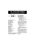
Button 1
Button 3
Button 2
System Operation
Button 4
ARMING OPERATION
To arm the system press transmitter button 1:
• The siren will chirp once.
• The parking lights will flash once.*
• The doors will lock.*
• The LED will start flashing within 5
seconds and the system will be armed.
After Arming, if a bad sensor or an open
zone is detected, the siren will chirp and the
parking lights will flash 4 times to indicate a
zone is open. The system will ignore that
input, keeping all other areas protected.
While Armed, the system will trigger if:
• The doors are opened.
• The shock sensor detects an impact.
• The hood or trunk is opened.
When triggered, the siren will soundand the
parking lights will flash* for 50 seconds.
If the same input triggers the system 3 times
during a single arming cycle, the system will
bypass that input, keeping other zones
protected, until the next arming cycle.
If the shock sensor detects a light impact to
the vehicle, the siren will chirp and the
parking lights will flash 3 times to warn away
the potential intruder.
*Optional Feature
Transmitter styles may vary
Standard Features:
Two 4-Button Remote Transmitters
Status indicator (LED)
Valet / override switch
Multi-tone siren (115dB)
Dual stage impact detector
Flashing parking lights
Remote panic
Remote sensor bypass
Passive or active arming
Anti-carjacking mode
Optional Features:
Starter disable
Keyless entry
Auxiliary Function
2nd Auxiliary Function
Remote trunk or hatch release
Illuminated entry
Hood and trunk protection
Remote auto start
Power window roll up
Back-up battery w/charging circuit
Perimeter sensor
PASSIVE ARMING
The passive arming feature allows the system
to arm itself automatically without user
intervention. The Passive Arming feature may be
enabled during installation.
Note: Some features may require additional
parts and labor, and may not be appropriate for
certain vehicles. Consult your authorized dealer.
1
BW2450.qxd
6/11/2009
4:12 PM
Page 2
To arm the system passively:
1. Turn the ignition key off.
2. Exit the vehicle and close all doors.
• The LED flashes rapidly indicating
that the system is preparing to arm.
• The siren will chirp 30 seconds after
the last door is closed to indicate the
system is now armed.
• The doors will lock.†*
†
REMOTE PANIC
In the event of an emergency, the system’s
siren can be triggered for 60 seconds to
attract attention.To activate the Panic Feature,
press transmitter Button 1 for 3 seconds:
• The siren will sound.
• The parking lights will flash*.
Press button 1 again to exit panic mode. For
4-button systems press button 1 or 2 to exit
panic mode (pressing button 2 will unlock
the doors and disarm the system).The Panic
Feature will not operate when ignition is on.
*Optional feature
If Passive Locking was enabled during installation.
DISARMING OPERATION
To disarm the system press button 1 again (or
button 2 on 4-button systems).
• The siren will chirp twice.
• The parking lights will flash twice then
remain on for 10 seconds.*
• The doors will unlock.* If using the
Driver Priority unlock feature only the
driver door will unlock. Press button 2
again to unlock all doors.
• The dome light will turn on for 30
seconds.*
EMERGENCY OVERRIDE
If the transmitter becomes lost or fails to
operate, the system can be disarmed by
using the emergency override feature.
To override the system:
1. Enter the vehicle.
• Because the system is armed, the
siren will sound.
2. Turn on the ignition key.
3. Press the Valet switch for 5 seconds.
• The siren will stop sounding.
• The starter defeat will be bypassed.
• The system will enter valet mode.
TAMPER ALERT
If the alarm was triggered while away, the
siren will chirp and the parking lights flash 3
times on disarm for tamper indication.
SILENT ARMING/DISARMING
Press buttons 1&2 then button 1 or 2 to Arm
or Disarm for one-time silent operation.
The system can also be programmed for fulltime silent operation during installation.
VALET MODE
When the system is placed into the Valet
Mode the security system will be disabled.
However, the optional keyless entry and
trunk release features will still function.
To enter or exit valet mode:
1. Be sure the system is disarmed.
2. Turn the ignition key on.
3. Press and hold the valet switch for 5
seconds.
• The siren will chirp 5 times to enter
valet or twice for exit.
• The LED will turn on solid indicating
IGNITION CONTROLLED LOCKS*
The ignition locks feature automatically locks
and unlocks the doors when the ignition is
cycled on or off. To avoid locking keys in the
vehicle, the ignition locking feature will be
cancelled if a door is open when the ignition
is turned on. This feature may be disabled
during installation.
2
BW2450.qxd
6/11/2009
4:12 PM
Page 3
the system is in valet mode, or turn
off indicating valet mode exit.
If the anti-carjack feature is triggered:
• The system will provide no indications
for 60 seconds.
• After 60 seconds, the siren will chirp for
10 seconds providing time to press the
valet switch and deactivate the system.
• If not deactivated with 10 seconds, the
system will enter full trigger mode.
• The parking lights will flash and the
siren will sound in full alarm.
• The starter defeat will turn on and until
the anti-carjack mode is deactivated.
To deactivate the anti-carjack when triggered:
1. Turn the ignition key off then back on.
2. Press the valet switch once.
• The siren will pause briefly.
3. Turn the ignition key off.
4. Press the transmitter button 2.
• The system will disarm.
OPTIONAL TRUNK RELEASE
Press button 3 for approximately 3 seconds
to open the trunk.
OPTIONAL 2ND AUX/CAR FINDER
Press button 4 for approximately 3 seconds
to activate the second auxiliary output/car
finder feature. When second auxiliary
function is activated, the parking lights will
flash 5 times and the siren will chirp as
confirmation. This output can be connected
to a relay to control additional functions like
power window roll-up, or an optional device
such as a remote car starter. If the output is
not connected, it still serves as a car finder
feature to identify the vehicle in a large
parking area.
OPTIONAL ANTI-CARJACK MODE
For added security while driving the vehicle,
the optional anti-carjacking feature will
activate whenever a door is opened after the
ignition has been turned on. This feature must
be enabled during installation.
LED INDICATIONS
On Solid = Valet Mode
On Solid when not in valet = Open Zone
Slow Flash = System Armed
Rapid Flash when disarmed = Passive
Arming
Rapid Flash when armed = Tamper Alert
PARKING LIGHT INDICATIONS
1 Flash = System Armed
2 Flashes then on solid for 10 seconds =
System Disarmed
3 Flashes = Tamper Alert
4 Flashes = Open Zone Indication (after
arming)
3
BW2450.qxd
6/11/2009
4:12 PM
Page 4
Installation Instructions
Before you begin the installation
• Read the INSTRUCTIONS!
• Always use a multi-meter verify wiring.
• Before mounting the product, verify
with the customer the desired location for
the valet switch and LED.
• Protect the vehicle using fender covers.
• Always look before drilling. Make sure
you will not cause damage to vehicle
hoses, electrical looms or physical
damage to vehicle.
internal jumper next to the relay as shown
on the back page diagram. NOTE: Do not
connect to the headlight circuit.
• BLACK WIRE - Ground input (-).
Connect to a solid chassis ground that is
clean and free of paint or dirt.
• RED WIRE - +12V Battery input.
Connect the red fused wire on the main
harness to a constant +12V source. This
wire should be at least a 15 amp supply.
• BROWN WIRE - Siren wire output (+)
2A. Connect to the siren’s red wire.
Connect the siren’s black wire to ground.
• GRAY WIRE - Auxiliary 1 output (-)
500mA. Connect to a relay for an optional
feature such as trunk release, etc.
• WHITE/BLUE WIRE - Auxiliary 2 output
(-) 500mA. Connect to a relay or module
for an optional feature such as power
window roll-up, etc.
• ORANGE WIRE - Armed Output (-)
500mA. Connect to a relay for optional
starter defeat (See wiring diagram). The
ORANGE wire provides a ground when
armed to activate a starter disable relay or
other device (i.e. window module, etc.).
• BLACK/WHITE WIRE - Dome Light
output (-) 500mA. Connect to an optional
relay to activate the vehicle’s dome light.
• WHITE/GREEN WIRE - Passenger
Unlock output (-) 500mA. Connect to a
relay to unlock the passenger doors when
wired for Driver Priority Unlocking.
• BLUE WIRE - Trunk/Hood trigger (-).
Connect the Blue wire to the trunk
and/or optional hood pin switches. The
switch must provide ground when opened.
• GREEN WIRE - Negative door trigger (-).
Connect to the door switch circuit wire that
Mounting System Module
Mount the system module under the
dash where it will be difficult for a thief
to locate, and away from moving parts.
Mounting Siren
Mount the siren in a suitable place under
the hood, away from hot and moving
engine parts such as manifolds, fan belts,
etc. Make sure the siren cannot be
accessed from underneath the vehicle or
through the grill. Face the siren down so
that water cannot accumulate inside the
siren bell. Protect wires running through
the engine compartment using split loom
tubing. If a new hole is needed, protect the
wire from chaffing by installing a grommet.
14-Pin Main Harness:
• WHITE WIRE - Parking Light output
(+/-) 10A relay. Connect to the vehicle’s
parking light wire. If the circuit exceeds 10
amps a relay is required. For vehicle’s with
independent left and right parking light
circuits, the wires must be connected
using diodes to keep the circuits separate.
For negative (-) trigger vehicles, move the
4
BW2450.qxd
6/11/2009
4:12 PM
Page 5
optional door lock relay module.
• BLUE WIRE - unlock output (-) 500mA.
• RED WIRE - not used.
• GREEN WIRE - lock output (-) 500mA.
3-Pin Small White Connector: Plug-in
port for dual stage shock sensor.
shows ground when the door is open.
• VIOLET WIRE - Positive door trigger (+).
Connect to the door switch circuit wire that
shows +12V when the door is open. This
type of circuit is common on Ford vehicles.
• YELLOW WIRE - +12V Ignition input.
Connect to a main ignition wire at the
ignition switch harness. This wire shows
+12V when the ignition is on and while
cranking. The voltage must not drop when
the car is starting.
Automatic Output Circuit Breaker
When any (-) output is connected to (+)
constant in error, the system detects the
short circuit automatically and shuts down
that output until the error is corrected
and ignition reset (on-off) is performed.
While the short circuit is detected, the
siren will chirp 4 times and the park lights
will flash 4 times during arm and disarm.
LED will continue to flash 2-9 times
depending on the output shorted until
ignition reset is performed (In both arm
and disarm mode).
NOTE: Do not connect the alarm module
until the installation is complete. Turn on the
ignition first, then plug in the 9-pin harness
followed by the 3-pin large harness so the
alarm will power up in the disarm state. If
the alarm is plugged in without the ignition
on, it will automatically power up in the
alarming state.
Plug in Connectors
2-Pin Red Connector: Plug-in port for
LED. Mount LED where it may be easily
seen from either side of the vehicle.
2-Pin Blue Connector: Plug-in port for
valet switch. Mount switch in an area
accessible from the driver’s seat.
3-Pin Large White Door Lock Connector:
Plug-in connector for door lock harness or
Programmable Features
Function
Buttons
Shock Sensor
3-3-1
Arming Chirps
2-1-1
Ignition Locking
1-3-2
Door Lock Pulse Length
1-3-1
Door Unlock Pulse
2-2-1
Passive Locking
3-3-2
Arming Mode
1-2-3
Anti-Carjack Activation
2-1-3
SHORT CIRCUIT LED INDICATIONS
2 Flashes = Lock Output
3 Flashes = Unlock Output
4 Flashes = Auxiliary Output
6 Flashes = Starter Defeat Output
7 Flashes = Dome Light Output
8 Flashes = Auxiliary 2 Output
9 Flashes = Passenger Unlock Output
1 Chirp
Off
Silent
Off
3 Seconds
Double
Off
Active
Disabled
*default settings in bold
5
2 Chirps
On
Normal
On
.75 Second
Single
On
Passive
Enabled
BW2450.qxd
6/11/2009
4:12 PM
Page 6
automatically lock with Passive Arming.
Arming Mode. Select either manual arming
(Active) or automatic arming (Passive).
Anti-Carjacking Activation. Enables or
disables the anti-carjacking feature.
Entering Programming
To enter System Programming:
1. Turn on ignition.
2. Within 5 seconds, press valet switch 5
times.
• The siren will chirp, to indicate
entering program mode.
3. Press the transmitter buttons shown
to change the desired feature.
• The siren will chirp once or twice to
indicate the setting.
4. Repeat the programming sequence to
change other selections.
5. Turn off ignition to save changes.
Test System
Arm and disarm system, checking that the
siren chirps and parking lights are
functioning normally, as well as Passive
Arming and Emergency Override. Make
sure that the programmed features are
performing correctly.
Test the doors and hood/trunk inputs
making sure all doors trigger the system.
Test the starter defeat feature (if installed).
Adjust the shock sensor.
Tie up wires, and replace any dash panels.
Make sure the customer knows the
location of the valet/override switch.
Complete Default Reset
Following this procedure will set all
programmable features to default settings.
1. Enter System Programming.
2. Press Transmitter Button 3 three
times.
• The siren will chirp 3 times
indicating all programmable features
are reset to factory default settings.
5. Turn off ignition.
Adding Transmitters
To add a new transmitter to the system
have the desired transmitters ready and
follow the Code Learning sequence.
To enter Code Learning Mode:
1. Turn the ignition on, off, on, off and
leave on.
• The siren will chirp once.
2. Press the Valet switch for 5 seconds.
• The siren will chirp 3 times.
3. Press the transmitter’s Lock Button.
• The siren will chirp once.
4. Repeat step 3 for each additional
transmitter (max 3).
5. Turn off the ignition.
• The siren will chirp once.
NOTE: If a transmitter is lost or stolen, make
sure to code all 3 transmitter memory
Programmable Features
Shock Sensor. Selects whether or not the
shock sensor will trigger the alarm.
Arming Chirps. Select Normal or Silent.
Ignition Locking. Automatically locks and
unlocks the doors with the ignition. The
system will not lock the doors if any door
is open when the ignition is turned on.
Door Lock Pulse Length. Sets the lock
pulse length for normal (.75 second) or
vacuum locking systems (3 seconds).
Door Unlock Pulse. Selects between a
single and double unlock pulse.
Passive Locking. Allows the doors to
6
BW2450.qxd
6/11/2009
4:12 PM
Page 7
locations. (Example: If only one transmitter is
used, repeat step 3 two times to remove any
previously programmed transmitters.)
Two Car Operation
Two cars with the same system can be
operated using a single transmitter. To
program Two Car operation, get both of
Car 2’s transmitters and a transmitter for
Car 1 and follow the steps below.
1. Follow steps 1 and 2 for Adding
Transmitters
2. Press the Lock Button on Car 2’s first
transmitter.
• The siren will chirp once.
3. Press the Lock Button on Car 2’s
second transmitter.
• The siren will chirp once.
4. Press Button 4 on Car 1’s transmitter.
• The siren will chirp once.
5. Turn off the ignition.
• The siren will chirp once.
Car 2 will operate normally with both it’s
transmitters and can now be operated
using Car 1’s transmitter as follows:
Car 2 arm- Press buttons 1&4 together on
Car 1 transmitter.
Car 2 disarm- Press buttons 2&4 together
on Car 1 transmitter.
Car 2 auxiliary 1 feature- Press buttons
3&4 together on Car 1 transmitter.
DOOR LOCK WIRING DIAGRAMS
NEGATIVE TRIGGER
(-) LOCK
L
(-) UNLOCK
UL
POSITIVE TRIGGER
DOOR
LOCK
RELAYS
(+) LOCK
L
LOCK/UNLOCK
SWITCH
LOCK/UNLOCK
SWITCH
86 87 85
87a
GREEN
GREEN
DOOR
LOCK
RELAYS
(+) UNLOCK
UL
30
BLUE
+12V
86 87 85
87a
BLUE
30
ADDING ACTUATORS
REVERSE POLARITY
+12V
GREEN
86 87 85
87a
UL
87
BLUE
30
BLUE
L
+12V
AFTER-MARKET
ACTUATORS
86 87 85
87a
86
87a
30
X
85
87
GREEN
30
7
86
87a
30
CUT
85
X
CUT
LOCK/UNLOCK
SWITCH
FACTORY DOOR
MOTOR
BW2450.qxd
6/11/2009
4:12 PM
Page 8
WIRING DIAGRAM
RELAY WIRING DIAGRAMS
POSITIVE TRIGGER
NEGATIVE TRIGGER
TO WIRE IN VEHICLE
TO WIRE IN VEHICLE
(-) OUTPUT
FROM ALARM
86 87 85
87a
(-) OUTPUT
FROM ALARM
86 87 85
87a
30
30
+12V
+12V
© 2009
64-2450 6/09 Rev. 2
8