1
USER GUIDE
Publication AP9967_1
Allen & Heath
1
XONE:43C User Guide
Limited One Year Manufacturer’s Warranty
Allen & Heath warrants the Allen & Heath - branded hardware product and accessories
contained in the original packaging ("Allen & Heath Product”) against defects in materials
and workmanship when used in accordance with Allen & Heath's user manuals, technical
specifications and other Allen & Heath product published guidelines for a period of ONE (1)
YEAR from the date of original purchase by the end-user purchaser ("Warranty Period").
This warranty does not apply to any non-Allen & Heath branded hardware products or any
software, even if packaged or sold with Allen & Heath hardware.
Please refer to the licensing agreement accompanying the software for details of your rights
with respect to the use of software (“EULA”).
Details of the EULA, warranty policy and other useful information can be found on the Allen &
Heath website: www.allen-heath.com/legal.
Repair or replacement under the terms of the warranty does not provide right to extension or
renewal of the warranty period. Repair or direct replacement of the product under the terms
of this warranty may be fulfilled with functionally equivalent service exchange units.
This warranty is not transferable. This warranty will be the purchaser’s sole and exclusive
remedy and neither Allen & Heath nor its approved service centres shall be liable for any
incidental or consequential damages or breach of any express or implied warranty of this
product.
Conditions of Warranty
The equipment has not been subject to misuse either intended or accidental, neglect, or
alteration other than as described in the User Guide or Service Manual, or approved by Allen
& Heath.
Any necessary adjustment, alteration or repair has been carried out by an authorised Allen &
Heath distributor or agent.
The defective unit is to be returned carriage prepaid to the place of purchase, an authorised
Allen & Heath distributor or agent with proof of purchase. Please discuss this with the
distributor or the agent before shipping. If the unit is to be repaired in a different country to
that of its purchase the repair may take longer than normal, whilst the warranty is confirmed
and parts are sourced. Units returned should be packed in the original carton to avoid transit
damage.
DISCLAIMER: Allen & Heath shall not be liable for the loss of any saved/stored data in
products that are either repaired or replaced.
Check with your Allen & Heath distributor or agent for any additional warranty information
which may apply. If further assistance is required please contact Allen & Heath Ltd.
Xone:43C complies with the European Electromagnetic Compatibility
directives 2004/108/EC and the European Low Voltage directives 2006/95/EC.
Any changes or modifications to the equipment not approved by Allen & Heath could
void the compliance of the product and therefore the users authority to operate it.
XONE:43C User Guide AP9967 Issue 1
Copyright © 2015 Allen & Heath Limited. All rights reserved
Allen & Heath Limited
Kernick Industrial Estate, Penryn, Cornwall, TR10 9LU, UK
http://www.allen-heath.com
Allen & Heath
2
XONE:43C User Guide
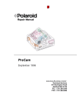
PACKED ITEMS
Check that you have received the following:
Mains Lead
Check that the correct
mains plug is fitted.
Xone:43C mixer
Spare knobs
and buttons
Type A-B USB Lead
To connect the Xone:43C to
your computer.
Safety Sheet
Important ! Read this sheet
before starting.
Retain for future reference.
Allen & Heath
3
XONE:43C User Guide
CONTENTS
Congratulations on purchasing the Allen & Heath Xone:43C DJ mixer.
The Xone:43C is a DJ mixer featuring four stereo dual input channels, a Mic/Aux input channel, 45mm
linear VCA channel faders, Xone VCF filter, X:FX external effects loop for send/return functionality
with wet/dry control, a 16 Channel 96kHz 24bit USB Soundcard and X:LINK connectivity.
To ensure that you get the maximum benefit from the unit please spare a few minutes
familiarizing yourself with the controls and setup procedures outlined in this user guide. For
further information please refer to the additional information available on our website, or
contact our product support team.
http://www.allen-heath.com
Warranty ........................................................
Packed Items ..................................................
Contents.........................................................
Setup Examples .............................................
Mic / Aux Channel Input .............................
Phono / USB / Line Input Channels . ........
Filter Section .................................................
Headphone Section ......................................
Master Section ..............................................
Crossfader .....................................................
Rear Connectors ..........................................
Driver Installation (Mac) .............................
Driver Installation (PC) ...............................
USB Soundcard (Default) ............................
USB Soundcard (User Options) ................
Serato DJ Setup ............................................
MIDI ................................................................
Panel Drawings ..............................................
Specifications .................................................
Block Diagram ...............................................
Filter Reference ............................................
Operating Levels ...........................................
Earthing...........................................................
Replacing the Crossfader ...........................
Allen & Heath
4
2
3
4
5
6
7
9
10
11
12
13
15
16
17
18
19
21
25
26
27
28
29
30
31
XONE:43C User Guide
SETUP EXAMPLES
Allen & Heath
5
XONE:43C User Guide
MIC / AUX INPUT CHANNEL
1
Standard 3-Pin XLR socket wired as Pin 1 = Ground, Pin
2 = hot (+), Pin 3 = cold (-).
1
2
2
3
Mic / Aux Select Switch
Selects either the XLR microphone input or the alternative Aux input.
5
4
Channel Gain Control
Adjusts the input sensitivity of the Mic / Aux channel to
compensate for different source signal levels.
6
7
Aux Input
Dual RCA sockets for connecting an external line level
source.
3
4
Mic Input
5
Channel Equaliser
The Mic / Aux input channel is equipped with a 2 band
EQ stage providing +15dB of boost when fully clockwise
and –15dB attenuation when fully anti-clockwise.
6
Cue Switch
Press the Cue switch to listen to the pre-channel on signal in the headphones and view its level on the main meters. Press the switch again to deselect cue.
7
Channel On Switch
Press the Channel On switch to send the channel audio
to the main mix.
Allen & Heath
6
XONE:43C User Guide
PHONO / USB / LINE INPUT CHANNELS 1 - 4
1
Channel Level Control
This control has a range from - 10dB to +10dB. Use it to
adjust the signal level of an audio source to give a nominal 0dB reading on the channel meter, with the peak level at or below 6dB.
1
2
2
Phono / USB / Line Select Switch
Selects either the RCA phono input, USB Soundcard input or the alternative RCA stereo line input.
3
3
Channel Equalizer / Isolator
The Xone:43C is equipped with a very powerful 3 band
EQ providing a controlled +6dB of boost when fully
clockwise, but dramatic cut of each band when fully anticlockwise. Centre frequencies are set at:
4
HF = 3.8kHz (high frequency, treble)
MF = 1kHz (mid frequency)
LF = 310Hz (low frequency, bass)
5
6
4
X:FX Dry / Wet Send
Use this control to vary the amount of channel signal
that is sent to an external effects device connected to
the X:FX send / return on the rear panel. With this
control set to ‘dry’, none of the signal is routed to the
external effects loop. With the control in the central
position, half of the signal is sent to external effects,
while the other half is unaffected or, if filter is selected,
only the dry part of signal is filtered. With the control
set to fully ‘wet’, all of the signal is sent to external effects and the VCF filter is bypassed.
5
XFade Assign Switch
Used to assign the channel to either the X (left), off
(middle) or Y (right) side of the cross-fader.
6
Filter Select
Press to route the channel signal through the VCF filter.
The switch will illuminate to indicate that the channel is
being sent to the filter.
Allen & Heath
7
XONE:43C User Guide
PHONO / USB / LINE INPUT CHANNELS 1 - 4
7
7
Press the Cue switch to listen to the channel pre-fade
signal in the headphones and see its level on the main
meters. Press the switch to deselect cue.
8
9
Cue Switch
8
Channel Meter
Displays the channel signal level. It is pre-EQ and prefader, allowing the input level to be displayed even if the
EQ is set to off on all bands.
The channel level control should be set so that the meter averages around ‘0’ with loudest peaks no higher
than ‘+6’. Turn down the level control if the +10 indicator lights.
9
Channel Fader
A high quality, smooth travel fader adjusts the channel
signal level from fully off to fully on.
Allen & Heath
8
XONE:43C User Guide
FILTER SECTION
1
This produces the classic Xone VCF sound by feeding
some of the filter output back to its input. The control
ranges from ‘mild’ producing a very subtle effect, to
‘wild’ producing a dramatic phase effect with feedback
just short of oscillation.
1
2
2
X:FX Return to Filter
Pressing this button routes the X:FX return to the VCF
filter, instead of directly into the main mix buss. The
effected channel signal can then be filtered as well, allowing extra versatility and creativity to be brought into the
mix.
3
4
5
Resonance Control
3
HPF
Turns on the high pass (bass cut) filter slope.
4
6
BPF
Turns on the band pass (bell shaped) filter slope.
5
LPF
Turns on the low pass (treble cut) filter slope.
6
Frequency Sweep Control
This control sets the –3dB cut-off frequency of the filter.
It ranges from very low frequency (20Hz) to very high
frequency (20kHz).
Allen & Heath
9
XONE:43C User Guide
HEADPHONE SECTION
1
1
Selects the way Cue operates. Normally, pressing a
channel Cue switch overrides both left and right monitor program signals with the stereo Cue signal. With
Split set to On, Cue overrides just the left channel leaving the program in the right channel. The left monitor
meter displays the Cue signal, right displays program.
This is very useful when beat mixing using headphones.
2
3
Split Cue Switch
2
Cue / Mix Control
Allows the main mix output to be added to the Cue signal. Turned fully anticlockwise, only the active Cue is
heard through the headphones when Cue is active.
Gradually turning clockwise introduces the main mix
output to the headphones, together with the active Cue.
Selecting Split Cue will automatically override this control.
4
3
Headphones Level Control
Adjusts the level of the signal in the stereo headphones.
This does not affect the level of the local booth monitor.
4
Headphone Outputs
Stereo 1/4” TRS jack and 3.5mm mini-jack sockets. Plug
in good quality stereo headphones intended for DJ monitoring. Use closed-ear headphones that provide maximum acoustic isolation when cueing your sources.
Allen & Heath
10
XONE:43C User Guide
MASTER SECTION
1
Mix / Monitor Meters
The main meters follow the selected monitor source.
The default display is the mix level, pre-master level,
which is overridden with an input channel level if the
channel cue switch is selected.
1
In split cue mode, the left (L) mix meter will display the
cued channel signal level and the right (R) mix meter will
display the mix level. The cued mix audio is pre level to
prevent mismatch due to the position of the master level control.
The mixer should be operated with these meters averaging around ‘0’ with loudest peaks no higher than ‘+6’.
2
2
Master Level Control
A rotary master control adjusts the level of the master
mix XLR outputs feeding the house sound system. This
does not affect the booth output or the meter reading.
3
3
Booth Level Control
Adjusts the level of the signal to the stereo booth RCA
output. This does not affect the headphones. The
booth output could be used for a booth monitor, recording or an additional zone feed.
Allen & Heath
11
XONE:43C User Guide
CROSSFADER
2
1
1
Crossfader
This lets you fade between signals routed to either side, typically to fade
smoothly into a new music track or to creatively layer sounds when scratch or
cut mixing.
The crossfader is a VCA controller which affects the level of signals routed via
the filters. Make sure the switches on the channels you wish to fade are set to
X or Y as appropriate.
2
Crossfader Curve Control
This control adjusts the crossfader curve between dipped, dipless and fast-cut,
better suited for scratch or cut mixing.
Allen & Heath
12
XONE:43C User Guide
REAR CONNECTORS
2
1
4
1
3
AC Mains Input
IEC cable with moulded mains plug suitable for your local supply.
Important: Read the SAFETY INSTRUCTIONS sheet included with the
Xone:43C and printed on the rear panel.
Check that the correct mains lead with moulded plug has been supplied with your console.
The power supply accepts mains voltages within the range 100-240V without changing any
fuses or settings. Ensure that the IEC mains plug is pressed fully into the rear panel socket
before switching on.
Note: It is standard practice to turn connected power amplifiers down or off before
switching the console on or off. This prevents any potential damage to speaker systems due
to switch-on transients.
2
CH 1, 2, 3 and 4 Phono Input
Plug in turntables with magnetic cartridges requiring RIAA equalisation. For non-RIAA turntables plug into the LINE input instead. Do not plug in line level sources to the phono inputs
as these will overload the preamp and cause severe high level distortion.
3
CH 1, 2, 3 and 4 Line Input
RCA phono. Connect stereo line level music sources such as CD players. Do not connect
turntables which require RIAA equalisation. Alternatively, you can connect to jack sources
using a cable with RCA to jack adapters. Avoid using low grade cables such as those often
supplied with domestic equipment as these can quickly prove unreliable in use.
4
X:LINK
Connect XONE:K Series Controllers to the XONE:43C Mixer to save using USB ports on
your computer.
Allen & Heath
13
XONE:43C User Guide
REAR CONNECTORS
4
6
5
4
7
8 9
10
USB Line / Phono select switches
Switches for selection between Control vinyl (Phono) or CD (Line) per input channel if using
Serato DJ Club Pack. See Page 19 for more information.
5
USB Soundcard
16 Channel 96kHz 24bit USB Soundcard. See Page 17 for more information.
6
Master Output
Balanced XLR. This is the main output that feeds the house PA system. Plug into the house
processor/amplifier system using balanced cables. Use balanced cables and equipment. When
the main meter LEDs are at “0dB” the output will nominally be at +4dBu. Do not unbalance
this output by shorting one phase to ground—for unbalanced operation use pin 2 only.
7
X:FX Send/Return
RCA phono. Connect your external effects device and use the X:FX dry / wet control to send
channel signals to the effects unit. The signal returns to the mix bus but can be routed to the
VCF filter by pressing the ‘X:FX’ button on the front panel filter section. This allows the filter
to be ‘stacked’ with an external effects device.
8
Record Output
RCA Phono, nominal 0dBu. Pre-level mix output for connection to external recording devices.
9
Booth Output
RCA phono nominal 0dBu. Provides a line level stereo feed to the DJ local monitor amplifier
system. It is not affected by the master fader or cue system.
10
Chassis Earth Terminal
A screw terminal is provided for connecting the earth straps from turntables. This connection
earths the metal parts of the turntable to reduce hum, buzz or similar audible noise getting into
the system.
Allen & Heath
14
XONE:43C User Guide
DRIVER INSTALLATION (MAC)
Drivers
Although the Xone:43C is class compliant and will work on a Mac without drivers, for best performance we
recommend you download the dedicated drivers from our website:
www.allen-heath.com/xone43cdrivers
When the drivers have downloaded, extract them to a folder and click on the .dmg file to start installation:
1. Click to load the Driver
2. Click Continue
4. Enter your user name and password then click
install software
3.
5.
Click Install
6.
Click Continue Installation
When the installation finishes, restart your
computer when prompted
Installation is complete and your computer will connect and recognise your Xone:43C as an audio and MIDI device.
Allen & Heath
15
XONE:43C User Guide
DRIVER INSTALLATION (PC)
Drivers
In order to access all the soundcard channels on your Xone:43C you will need to install the dedicated ASIO
driver, which can be downloaded from our website:
www.allen-heath.com/xone43cdrivers
When the drivers have downloaded, extract them to a folder and click on the setup file to start installation:
1.
Choose your language and
click OK to continue
2.
3.
4.
Click Install the driver
During the installation you will twice be asked to unplug
and re-plug the USB audio cable to your Xone:43C
Restart your computer when prompted
After restart, installation is complete and your computer will now connect and recognise your Xone:43C as an
audio and MIDI device.
Allen & Heath
16
XONE:43C User Guide
USB SOUNDCARD — DEFAULT
The Xone:43C includes a 16 Channel (8 in / 8 out) 96kHz 24bit USB Soundcard.
By default, the mixer ships with the soundcard configured to offer the best workflow to suit Serato DJ.
DEFAULT USB AUDIO ROUTING
Mixer -> Computer
Input Channel
Xone 43C
USB_1
(RIAA or LINE)SND_L_1
USB_2
(RIAA or LINE)SND_R_1
USB_3
(RIAA or LINE)SND_L_2
USB_4
(RIAA or LINE)SND_R_2
USB_5
(RIAA or LINE)SND_L_3
USB_6
(RIAA or LINE)SND_R_3
USB_7
(RIAA or LINE)SND_L_4
USB_8
(RIAA or LINE)SND_R_4
Computer -> Mixer
Output Channel
Xone 43C
USB_1
USB_RTN_L_1
USB_2
USB_RTN_R_1
USB_3
USB_ RTN _L_2
USB_4
USB_ RTN _R_2
USB_5
USB_ RTN _L_3
USB_6
USB_ RTN _R_3
USB_7
USB_ RTN _L_4
USB_8
USB_ RTN _R_4
See the next page (18) for Soundcard user options.
Allen & Heath
17
XONE:43C User Guide
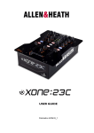
USB SOUNDCARD — USER OPTIONS
The Xone:43C Soundcard can be reconfigured beyond the default shipping configuration. To make any
changes via the jumpers you will need to open the mixer, see Page 31 for information on how to do this.
USB AUDIO ROUTING WITH JUMPER SETTINGS
Mixer -> Computer
Input Channel
Xone 43C DEFAULT
Xone 43C Jumper OPTION
USB_1
(RIAA or LINE)SND_L_1 (CN14 1+2)
REC_LEFT (CN14 2+3)
USB_2
(RIAA or LINE)SND_R_1 (CN15 1+2)
REC_RIGHT (CN15 2+3)
USB_3
(RIAA or LINE)SND_L_2 (CN16 1+2)
X_FX_L_SND (CN16 2+3)
USB_4
(RIAA or LINE)SND_R_2 (CN17 1+2)
X_FX_R_SND (CN17 2+3)
USB_5
(RIAA or LINE)SND_L_3 (CN18 1+2)
REC_LEFT (CN18 2+3)
USB_6
(RIAA or LINE)SND_R_3 (CN19 1+2)
REC_RIGHT (CN19 2+3)
USB_7
(RIAA or LINE)SND_L_4 (CN20 1+2)
X_FX_L_SND (CN20 2+3)
USB_8
(RIAA or LINE)SND_R_4 (CN21 1+2)
X_FX_R_SND (CN21 2+3)
Computer -> Mixer
Output Channel
Xone 43C
No Option Set To
USB_1
USB_2
USB_3
USB_4
USB_5
USB_6
USB_7
USB_8
USB_RTN_L_1
USB_RTN_R_1
USB_ RTN _L_2
USB_ RTN _R_2
USB_ RTN _L_3
USB_ RTN _R_3
USB_ RTN _L_4
USB_ RTN _R_4
USB_RTN_L_1
USB_RTN_R_1
USB_ RTN _L_2
USB_ RTN _R_2
USB_ RTN _L_3
USB_ RTN _R_3
USB_ RTN _L_4
USB_ RTN _R_4
The above table details the default USB Audio routing with Jumper Settings. To make any changes, lift (in
a pair) the jumpers from pins 1+2 to pins 2+3, this then enables the option setting.
CH1 CH2
RL RL
CH3 CH4
RL RL
PIN
3
2
1
Allen & Heath
DEFAULT E.G.
CH3 DEFAULT CH4 DEFAULT
MODIFIED E.G.
CH3 DEFAULT CH4 OPTION
18
XONE:43C User Guide
SERATO
The XONE:43C DJ Mixer features Serato DJ support. Users wanting to take advantage of this
are required to purchase Serato DJ Club Kit available in-app and at: http://store.serato.com/
Please note: Mixer does not support full control of Serato Video.
Serato NoiseMap™ Control Vinyl & CD
Vinyl is available from most DJ retailers and the Serato Store in a variety of colours
and collectors pressings: http://store.serato.com/
You can burn your own Serato Control CDs or use the Control Signal .wav file directly from a removable storage device. Download: http://serato.com/controlcd/
SERATO DJ SETUP
To connect the XONE:43C to a computer, download and install the latest drivers for your computers
operating system from our website:
http://www.allen-heath.com/xone43cdrivers
Connect the XONE:43C to your computer using the supplied type A-B USB Lead.
OS X
The XONE:43C is class compliant on a Mac, however we strongly recommend using the dedicated
driver for improved performance. See Page 15 for driver installation instructions.
Windows
The XONE:43C with Windows computers requires a dedicated driver.
See Page 16 for driver installation instructions.
Choosing DVS or Control CD with Serato DJ
With your computer connected via USB to the XONE:43C, connect your turntables / CD Media
players to the Phono / Line inputs.
On the channel input that has the turntable or CD Media player connected, select the appropriate USB select
switch for Phono or Line.
Allen & Heath
19
XONE:43C User Guide
SERATO DJ SETUP
On the top panel, find the corresponding music channel and select the input selector switch to USB
(middle position).
Serato DJ
Navigate to the 'Setup' screen in Serato
DJ.
1.
Click 'Expansion Packs'
2.
Click ‘Vinyl/CDJ Control’ to check
this is enabled
3.
*You are now ready to use CD
players or turntables with the
XONE:43C Mixer.
*Users wanting to take advantage of this are required to purchase Serato DJ Club Kit in-app or
available at: http://store.serato.com/
Connecting a XONE:K Series Controller
The XONE:43C includes X:LINK allowing you to expand your setup by connecting directly to the
XONE:K Series MIDI Controllers. X:LINK uses a standard RJ45 connector and distributes power
and MIDI data, without using additional USB ports.
The XONE:K Series Controllers are pre-mapped for use with Serato DJ via X:LINK only.
Using the RJ45 patch lead supplied with the XONE:K Series controller, connect the
RJ45 cable to the X:LINK OUT socket of the controller.
Connect the RJ45 cable to the X:LINK socket of the XONE:43C mixer.
Allen & Heath
20
XONE:43C User Guide
MIDI
MIDI stands for Musical Instrument Digital Interface, and is an interface protocol from the
nineteen eighties to enable different keyboards, sequencers, drum machines, etc. to communicate
with each other.
MIDI is still a common interface used by most DAW software to allow remote control of various
functions within the program.
The Xone:43C has the ability to send and receive MIDI. Including 18 MIDI enabled controls, 14
Buttons and 4 Faders that can be assigned to enable control of various parameters in a DAW such
as Ableton Live or Traktor:
The Default MIDI Channel is 16 (Hex = 0F)
You can change MIDI channel by holding down the Mic/Aux channel CUE button when powering
on the mixer. The CUE button will then flash to show you are in MIDI setup mode.
Channel 1-4 CUE buttons will display the current MIDI channel number in Binary.
Use the HPF & LPF buttons to cycle through MIDI channels.
Once you have selected the MIDI channel to use, press the flashing Mic/Aux channel CUE button
to exit the MIDI setup mode.
The MIDI channel is saved in memory and will be remembered when you power off the mixer.
See the next page for a table on converting binary to decimal.
Allen & Heath
21
XONE:43C User Guide
MIDI
MIDI Channel Setup
1
9
2
10
3
11
4
12
5
13
6
14
7
15
8
16
MIDI Parameters
All MIDI in Hex
n = MIDI Channel number
xx = Parameter number
Control Change messages (CC):
Bn xx 00 - 7F
Note On Messages:
9n xx 7F
Note Off Messages
9n xx 00
Allen & Heath
22
43C
CHANNEL
FADER
1
CC = Bn 00 00-7F
2
CC = Bn 01 00-7F
3
CC = Bn 02 00-7F
4
CC = Bn 03 00-7F
XONE:43C User Guide
MIDI
MIC/Aux Channel
Mic Cue
On = 9n 5C 7F
Off = 8n 5C 00
Mic ON
On = 9n 5D 7F
Off = 8n 5D 00
Channel CUE
Channel 1
On = 9n 4D 7F
Off = 8n 4D 00
Channel 2
On = 9n 39 7F
Off = 8n 39 00
Channel 3
On = 9n 25 7F
Off = 8n 25 00
Channel 4
On = 9n 11 7F
Off = 8n 11 00
Channel Filter
Channel 1
On = 9n 49 7F
Off = 8n 49 00
Channel 2
On = 9n 35 7F
Off = 8n 35 00
Channel 3
On = 9n 21 7F
Off = 8n 21 00
Channel 4
On = 9n 0D 7F
Off = 8n 0D 00
XFX / Filter
Allen & Heath
X:FX
On = 9n 04 7F
Off = 8n 04 00
HPF
On = 9n 01 7F
Off = 8n 01 00
BPF
On = 9n 02 7F
Off = 8n 02 00
LPF
On = 9n 03 7F
Off = 8n 03 00
23
XONE:43C User Guide
MIDI NOTE IMPLEMENTATION TABLE
Note Numbers
Octave
C
C# /Db
D
D# / Eb
-1
0
0
1
1
2
0
12
0C
13
0D
1
24
18
25
19
2
36
24
37
3
48
30
4
60
3C
5
72
6
7
8
108 6C 109 6D 110 6E 111
9
2
3
14
0E
26
1A
25
38
49
31
61
3D
48
73
84
54
96
60
E
3
4
15
0F
27
1B
26
39
50
32
62
3E
49
74
85
55
97
61
F
4
5
16
10
28
1C
27
40
51
33
63
3F
4A
75
86
56
98
62
F# / Gb
G
G# / Ab
A
A# / Bb
B
5
6
6
7
7
8
8
9
9
10
0A
11
0B
17
11
18
12
19
13
20
14
21
15
22
16
23
17
29
1D
30
1E
31
1F
32
20
33
21
34
22
35
23
28
41
29
42
2A
43
2B
44
2C
45
2D
46
2E
47
2F
52
34
53
35
54
36
55
37
56
38
57
39
58
3A
59
3B
64
40
65
41
66
42
67
43
68
44
69
45
70
46
71
47
4B
76
4C
77
4D
78
4E
79
4F
80
50
81
51
82
52
83
53
87
57
88
58
89
59
90
5A
91
5B
92
5C
93
5D
94
5E
95
5F
99
63 100 64 101 65 102 66 103 67 104 68 105 69 106 6A 107
6B
6F
77
112 70 113 71 114 72 115 73 116 74 117 75 118 76 119
120 78 121 79 122 7A 123 7B 124 7C 125 7D 126 7E 127
7F
DEC HEX DEC HEX DEC HEX DEC HEX DEC HEX DEC HEX DEC HEX DEC HEX DEC HEX DEC HEX DEC HEX DEC HEX
Allen & Heath
CC
Hex
Note
0
0x00
C-1
1
0x01
C#-1
2
0x02
D-1
3
0x03
D#-1
4
0x04
E-1
5
0x05
F-1
6
0x06
F#-1
7
0x07
G-1
8
0x08
G#-1
9
0x09
A-1
10
0x0A
A#-1
11
0x0B
B-1
12
0x0C
C0
13
0x0C
C#0
14
0x0D
D0
15
0x0E
D#0
16
0x10
E0
17
0x11
F0
18
0x12
F#0
19
0x13
G0
20
0x14
G#0
21
0x15
A0
24
XONE:43C User Guide
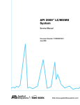
PANEL DRAWINGS
Rear Panel
Front Panel
Allen & Heath
25
XONE:43C User Guide
SPECIFICATIONS
Nom / max output levels
Main Mix
+4dBu
+27dBu
Booth
0dBu
+22dBu
X:FX Send
0dBu
+20dBu
Record Out
0dBu
+20dBu
Internal headroom
Channels +20dB
Frequency response
+/-0.5dB 20Hz - 20kHz
Distortion
< 0.05% THD+noise @1kHz
Crosstalk
< -83dB inter-channel
Residual noise
Mix 1
-89dBu
Booth
-93dBu
X:FX
-77dBu
Rec
-92dBu
Mix 1
-82dBu
Booth
-84dBu
X:FX
-77dBu
Rec
-87dBu
Mix noise
Channel meters
Peak reading 9 LED -20dB to +10dB
Main meters
Peak reading 9 LED -20dB to +10dB
Mic EQ
2-Band +/-12dB
Channel EQ
3-Band +6dB / total kill
Channel fader
45mm stereo VCA, < -85dB shutoff
Crossfader
45mm stereo VCA - replaceable
Filters
Stereo VCF, analogue
Digital Architecture Specification
Analogue/Digital conversion
Analogue/Digital Line-up
USB soundcard sampling frequency range
Consumption
24 bit
+14dBu = 0dBFS
44.1kHz to 96kHz
30W max
Dimensions and Weights
The console is fitted with rubber feet for desktop operation.
Mixer
Allen & Heath
Width
Height
Depth
Weight
320 mm
110mm
370mm
5.2 kg
26
XONE:43C User Guide
BLOCK DIAGRAM
Allen & Heath
27
XONE:43C User Guide
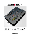
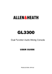
FILTER REFERENCE
The VCF Filters
A voltage controlled filter is an audio filter where the cut-off frequency is altered by a DC
control voltage rather than a variable resistor. This produces a much wider operating
range and more control over the filter response to create unlimited combinations of
tonal effect.
Filter Type Select
The filters are ‘state variable’. This means that they provide three simultaneous filter
HI-PASSband-pass
FILTER and low-pass. Three large illuminated switches select which
types: high-pass,
type is active. You can press any combination together to create different response types
+15
such as ‘notch’ and an interesting ‘all-pass’ effect. The switches are ‘soft switched’ for live
performance, meaning that the audio signal is ramped between filter states to prevent
+10
audible
LOclicks.
HI
+5
Note that the last selected type is lost when power is removed from the console. The
0dB
LPF is always selected when power is applied.
-5 The graphs below show the effect on the audio frequency response for the three filter
HI-PASS FILTER
+20
types. The range of sweep from low to high frequency
is shown together with the effect
-10
of adjusting RESONANCE (one frequency with several
resonance settings shown).
+15
-15
The vertical scale shows the amount of cut or boost
around the normal 0dB operating
+10
level.
The
horizontal
scale
shows
the
change
in
frequency
from low (bass) to high
-20
LO
HI
20
100
1kHz
10k
20k
(treble).
+5
+20
0dB
BAND-PASS
FILTER
HI-PASS FILTER
+20
+20
-5
+15
+15
+10
+10
+5
+5
-10
-15
LO
LO
HI
HI
-20
20
100
1kHz
10k
20k
10k
20k
0dB
0dB
-5
-5
-10
-10
+15
-15
-15
-20
-20
BAND-PASS FILTER
+20
+10
20
20
100
100
1kHz
1kHz
10k
10k
20k
20k
LO
+5
HI
0dB
+20
+20
LO-PASS
FILTER
BAND-PASS
FILTER
-5
+15
+15
-10
+10
+10
-15
+5
+5
LOLO
HI
HI
-20
20
100
1kHz
0dB
0dB
-5
-5
+20
-10
-10
+15
-15
-15
-20
-20
LO-PASS FILTER
+10
20
20
Allen & Heath
+20
+15
100
100
1kHz
1kHz
LO-PASS FILTER
10k
10k
20k
20k
28
+5
0dB
-5
-10
LO
HI
XONE:43C User Guide
OPERATING LEVELS
It is most important that the system level settings are correctly set. It is well known that
many DJs push the level to maximum with meters peaking hard in the belief that they are
getting the best from the system. THIS IS NOT THE CASE ! The best can only be
achieved if the system levels are set within the normal operating range and not allowed to
peak. Peaking simply results in signal distortion, not more volume. It is the specification of
the amplifier / speaker system that sets the maximum volume that can be achieved, not the
console. The human ear too can fool the operator into believing that more volume is
needed. Be careful as this is in fact a warning that hearing damage will result if high listening levels are maintained. Remember that it is the QUALITY of the sound that pleases the
ear, not the VOLUME.
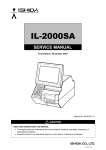
The diagram below illustrates the operating range of the audio signal.
NORMAL OPERATING RANGE. For normal music the signal should range between
–6 and +6 on the meters with average around 0dB. This allows enough HEADROOM for
unexpected peaks before the signal hits its maximum CLIPPING voltage and distorts.
It also achieves the best SIGNAL-TO-NOISE-RATIO by keeping the signal well above
the residual NOISE FLOOR (system hiss).
The DYNAMIC RANGE is the maximum signal swing available between the residual
noise floor and clipping.
!
Allen & Heath
An important note …
The human ear is a remarkable organ with the ability to compress or ‘shut down’ when sound levels become too high. Do
not interpret this natural response as a reason to turn the system volume up further ! As the session wears on ear fatigue
may set in, and the speaker cones may become hot so reducing
the effectiveness of the system and listeners to gain any benefit
from increased volume.
29
XONE:43C User Guide
EARTHING
The connection to earth (ground) in an audio system is important for
two reasons:
SAFETY - To protect the operator from high voltage electric shock,
and
AUDIO PERFORMANCE - To minimise the effect of earth (ground)
loops which result in audible hum and buzz, and to shield the audio
signals from interference.
For safety it is important that all equipment earths are connected to
mains earth so that exposed metal parts are prevented from carrying
high voltage which can injure or even kill the operator. It is
recommended that a qualified system engineer check the continuity of
the safety earth from all points in the system including microphone
bodies, turntable chassis, equipment cases, and so on.
The same earth is also used to shield audio cables from external
interference such as the hum fields associated with power transformers,
lighting dimmer buzz, and computer radiation. Problems arise when the
signal sees more than one path to mains earth. An ‘earth loop’ (ground
loop) results causing current to flow between the different earth paths.
This condition is usually detected as a mains frequency audible hum or
buzz.
To ensure safe and trouble-free operation we recommend the following:
Have your mains system checked by a qualified electrician. If
the supply earthing is solid to start with you are less likely to experience
problems.
Do not remove the earth connection from the console mains
plug. The console chassis is connected to mains earth through the
power cable to ensure your safety. Audio 0V is connected to the
console chassis internally. If problems are encountered with earth loops
operate the audio ‘ground lift’ switches on connected equipment
accordingly, or disconnect the cable screens at one end, usually at the
destination.
Make sure that turntables are correctly earthed. A chassis earth
terminal is provided on the console rear panel to connect to turntable
earth straps.
Use low impedance sources such as microphones and line level
equipment rated at 200 ohms or less to reduce susceptibility to
interference. The console outputs are designed to operate at very low
impedance to minimise interference problems.
Use balanced connections for microphones and mix output as
these provide further immunity by cancelling out interference that may
be picked up on long cable runs. To connect an unbalanced source to a
balanced console input, link the cold input (XLR pin 3 or jack ring) to 0V
earth (XLR pin 1 or jack sleeve) at the console. To connect a balanced
XLR output to unbalanced equipment, link the cold output to 0V earth
at the console.
Use good quality cables and connectors and check for correct
wiring and reliable solder joints. Allow sufficient cable loop to prevent
damage through stretching.
If you are not sure ... Contact your service agent or local Allen &
Heath dealer for advice.
Allen & Heath
30
XONE:43C User Guide
REPLACING THE CROSSFADER
If the crossfader is subject to a lot of use it will, in time wear out and need replacing. Intermittent or
noisy operation is an indication that it is becoming worn. Using a propriety fader cleaner such as
CaigLube might temporarily restore use, but DO NOT use on a new fader as it will wash away the factory applied grease.
The standard fader can be ordered under A&H part number 004-632JIT
The Innofader can be ordered under part number 004-504JIT
Warning! Dismantling your mixer could invalidate the warranty; if you are unsure of your ability to safely
carry out this work then it is advised that you leave it to a qualified service technician.
Tools you will need:
T8 Torx screwdriver
A small container to keep screws in.
Have a clean flat work surface ready before starting work.
Ensure that the power to the unit has been turned off and disconnected completely from the mains.
Step 1:
Remove and retain 2 screws from front panel.
Remove and retain 4 screws from rear panel
upper phono sockets.
Step 2:
Remove and retain 4 screws from side panel
of the mixer (2 each side).
Turn console over onto its front panel –
take care not to scratch the unit.
Step 3:
Remove and retain 6 screws from base panel.
Note that the 2 nearest the rear connector
remain in place.
Turn console over to be the correct way up.
Allen & Heath
31
XONE:43C User Guide
REPLACING THE CROSSFADER
Step 4:
Gently slide the two halves of the console
apart until the rear connector PCB is wholly
visible.
Step 5:
With care unplug the two grey flat wireforms
from the connector PCB.
The console base and front panel can now be
separated.
Step 6:
Remove the crossfader cap.
Remove and retain 2 screws from crossfader
front panel.
Step 7:
With care unplug the white harness from the
connector PCB.
The cross fader and plate can now be separated.
Step 8:
Remove and retain 2 screws from crossfader
plate.
Note that these 2 screws from the cross fader plate are a different size length, do not mix
them up with the other screws.
Allen & Heath
32
XONE:43C User Guide
REPLACING THE CROSSFADER
Step 9:
Fit the new replacement crossfader to the
bracket as shown (slot 1).
The longer (slot 2) beneath is for mounting
the optional Innofader (not supplied).
The standard crossfader must be fitted to slot
1 and not slot 2.
1
2
Step 10:
Screw the crossfader plate back to the console.
Replace the crossfader cap.
Connect the white harness from the connector PCB.
Step 11:
Re-assembly of the console is the reverse of
steps 1-5. When re-assembling the console
take great care to refit the wireforms fully
into the socket.
Allen & Heath
33
XONE:43C User Guide