1
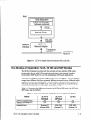
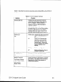
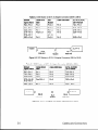
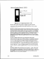
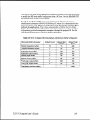
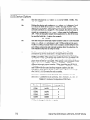
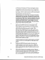
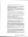
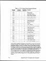
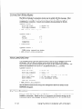
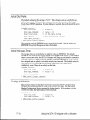
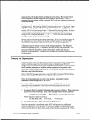
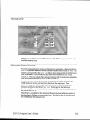
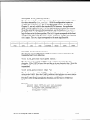
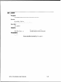
Table 3.1 PC DB-9 to DB-9 Connection
PC Connector
DB-9 Male
Cable DB-9
Female
Cable DB-9
Male
RxD
Pin 2
Pin 2
Pin 2
TxD
Pin 3
Pin 3
Pin 3
1 Pin 5
Pin 5
Pin 5
Signal Name
Signal Ground
I
I
I
I
DB9 Female
SLTA-10
WE)
PC (DTE)
DB-9
female end
DB-9
male end
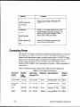
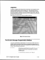
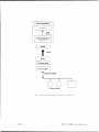
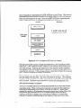
Figure 3.1 DB-9 to DB-9 Connection
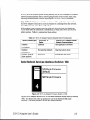
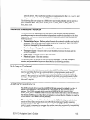
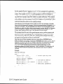
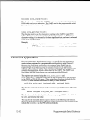
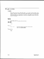
If using a PC or modem equipped with a DB-25 connector, then use a cable equipped
on one end with a DB-25 female connector and a DB-9 male connector on the other
end. Plug the male DB-9 connector into the SLTA-10 Adapter and the female DB-25
connector into the PC.
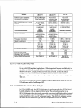
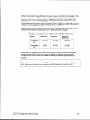
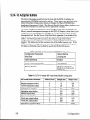
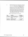
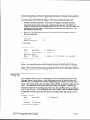
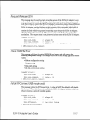
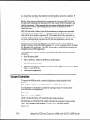
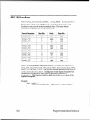
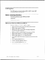
Table 3.2 PC 25Pin to DB-9 Connection
Signal Name
PC Connector
DB-25 Male
Cable DB-25
Female
Cable DB-9
Male
SLTA (DCE)
DB-9 Female
RxD
Pin 3
Pin 3
Pin 2
Pin 2
TxD
Pin 2
Pin 2
Pin 3
Pin 3
Signal Ground
Pin 7
Pin 7
Pin 5
Pin 5
T
PC (DTE)
DB-25
female end
DB-9
male end
SLTA-10
WE)
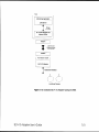
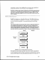
Figure 3.2 PC 25-Pin to DB-9 Connection
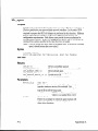
Attaching
the SLTA-10 Adapter
to a Modem
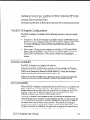
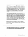
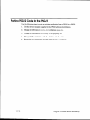
You must use a specific null modem cable to attach the SLTA-10 Adapter to a
modem. See the following tables and figures for the correct cable.
SLTA-10 Adapter
User’s Guide
3-3