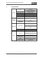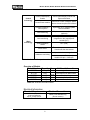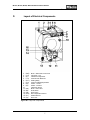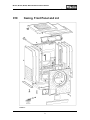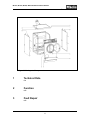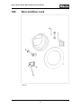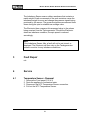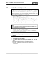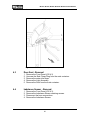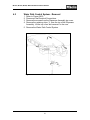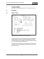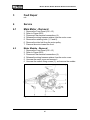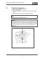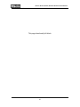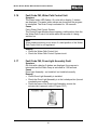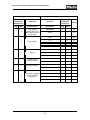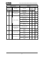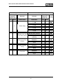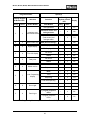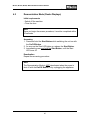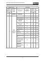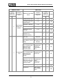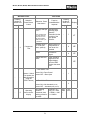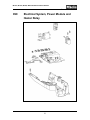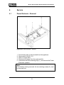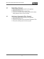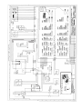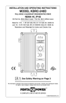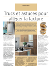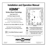
1
TECHNICAL INFORMATION
Touchtronic Clothes Washers
Includes: W1113, W1119, W1203, W1213, W1215
© 2004 Miele
This page intentionally left blank.
Touchtronic Washers – Table of Contents
A
WARNING and SAFETY INSTRUCTIONS
B
MODIFICATION HISTORY
C
TECHNICAL DATA
D
LAYOUT OF ELECTRICAL COMPONENTS
010 CASING, FRONT PANEL and LID
1
Technical Data
11
2
Function
11
3
Fault Repair
4
Service
11
12
4.1
Lid Removal
12
4.2
Plinth Removal
12
4.3
Front Panel Removal
12
4.4
Side Panel Removal
13
020 DOOR AND DOOR LOCK
1
Technical Data
17
2
Function
17
2.1
Electro-Mechanical Door Lock
17
3
Fault Repair
17
4
Service
17
030 SUDS CONTAINER, DRUM, BEARING and HEATER ELEMENT
1
Technical Data
2
Function
21
22
2.1
Heating Overheating Protection
22
2.2
Temperature Sensor NTC
22
2.3
Foam Sensing
23
2.3.1
Excess Foam When Heating During Main Wash
23
2.3.2
During Rinsing Excess Foam in the Drum Vent or Order Trap
23
2.3.3
During Spinning Excess Foam in the Drum
23
030 SUDS CONTAINER, DRUM, BEARING and HEATER ELEMENT (continued)
2.4
Imbalance Sensor
23
3
Fault Repair
24
4
Service
24
4.1
Temperature Sensor Removal
24
4.2
Heater Element Replacement
25
4.3
Door Seal Removal
26
4.4
Imbalance Sensor Removal
26
040 WATER INTAKE
1
Technical Data
2
Function
2.1
3
4
29
29
Water Path Control System
29
Fault Repair
30
3.1
30
Spin Before First Water Intake Not Possible
Service
30
4.1
Detergent Dispenser Removal
30
4.2
Water Path Control System Removal
31
050 DRAINAGE
1
Technical Data
2
Function
2.1
34
34
Increasing Drain Pump Head Height to 1.8 M
34
3
Fault Repair
34
4
Service
35
4.1
Drain Pump Removal
35
4.2
Non-Return Valve Removal
36
060 DRIVES
1
Technical Data
39
2
Function
39
2.1
Motor Control
39
3
Fault Repair
40
4
Service
40
4.1
Main Motor Removal
40
4.2
Motor Module Removal
40
4.3
Motor Brush Exchange
41
070 FASCIA PANEL and CONTROLS
1
Technical Data
2
Function
2.1
3
4
45
45
Fault Dialogue
45
Fault Repair
45
3.1
Fault Indication Quick Reference
45
3.2
Check Inlet and Drain LED’s Flash Together
47
3.3
Digital Display Shows - - -
47
3.4
Fault Code F1 NTC Sensor Short Circuited
48
3.5
Fault Code F2 NTC Sensor Open Circuited
48
3.6
Fault Code F10 Water Intake
49
3.7
Fault code F11 Water Drainage
50
3.8
Fault Code F15 Hot Water Intake
51
3.9
Fault Code F16 Excess Foam
52
3.10 Fault Code F20 Heating
52
3.11 Fault Code F41 Faulty EEPROM / Data Fault
53
3.12 Fault Code F43 Control / Power Electronic incompatible
53
3.13 Fault Code F47 Control / Power Module Interface Fault
53
3.14 Fault Code F51 Pressure Sensor
54
3.15 Fault Code F53 Tachogenerator
54
3.16 Fault Code F63 Water Path Control Unit
55
3.17 Locked LED Lights Up
55
3.18 Locked LED Flashes
56
Service
57
4.1 Programming Mode
57
4.2 Demonstration Mode Activation/Deactivation
65
4.3 Service Mode
67
090 ELECTRICAL SYSTEM, POWER MODULE AND HEATER RELAY
1
Technical Data
77
2
Function
77
2.1
Heater Relay Switching
77
3
Fault Repair
77
4
Service
78
4.1
Power Electronic – Removal l
78
4.2
Heater Relay - Removal
79
4.3
Interference Suppression Filter – Removal
79
Touchtronic Clothes Washers - List of Figures
D-1
Layout of Electrical Components
7
010-1
Layout of Components
11
030-1
Imbalance Sensor
23
030-2
Heater Element Replacement
26
040-1
Water Path Control System (Close-Up)
29
040-2
Water Path Control System
31
050-1
Drain Pump Removal
35
060-1
Pulse Width Modulation Motor Speed Control
39
060-2
Main Motor Assembly
40
060-3
Motor Brush Replacement
41
070-1
Drum Lamp Assembly
55
090-1
Power Electronic Removal
78
Touchtronic Clothes Washers - List of Tables
C-1
Technical Data (1 of 2)
5
C-2
Technical Data (2 of 2)
6
C-3
Overview of Model Numbers
6
C-4
Electrical Information
6
030-1
Technical Data
21
030-2
Temperature Sensor Values
22
040-1
Water Path Control System
29
050-1
Drain Pump Specifications
34
070-1
Fault Indication Quick Reference
45
070-2
Fault Indication Quick Reference Continued
46
070-3
Programmable Functions
58
070-4
Programmable Functions Continued
59
070-5
Programmable Functions Continued
60
070-6
Programmable Functions Continued
61
070-7
Programmable Functions Continued
62
070-8
Programmable Functions Continued
63
070-9
Service Mode
71
070-11
Service Mode
72
070-12
Service Mode
73
W1113, W1119, W1203, W1213 & W1215 Clothes Washers
Technical Information
A
Warning and Safety Instructions
1
General Information
Service of this appliance should only be performed by qualified
personnel; in accordance with local and national codes.
Power should be disconnected from the appliance during service
procedures. Unplug the appliance or shut off the appropriate circuit
breaker.
1
W1113, W1119, W1203, W1213 & W1215 Clothes Washers
Technical Information
This page intentionally left blank.
2
W1113, W1119, W1203, W1213 & W1215 Clothes Washers
Technical Information
B
Modification History
04/2004
Miele USA
3
Preliminary Information
W1113, W1119, W1203, W1213 & W1215 Clothes Washers
Technical Information
This page intentionally left blank.
4
W1113, W1119, W1203, W1213 & W1215 Clothes Washers
Technical Information
C
Technical Data
Frontloader
Version
Spaceframe construction
Casing
Suds
container
Fascia panel version
Light-touch buttons
Door lock
Electromagnetic release
Drum
Honeycomb drum
Drum diameter
480 mm (18.9 in.)
Maximum load, dry
laundry
5 Kg (11.02 lbs) – W1113 and W1119
6 Kg (13.23 lbs)– W1203, W1213 and
W1215
Drum opening
dimensions
300 mm (11.81 in)
Cold water connection: Water Path
Control Unit and single solenoid valve
Water path
Water intake
Hot water connection: Single solenoid
valve
Drainage
240VAC Drain Pump
Belt drive
Ribbed drive belt, motor spindle
diameter: 27.5 mm (1.08 in.), axiscenter difference: 366 mm (14.41 in.),
gearing (no. of motor rotations for one
drum rotation): 10.6
Drive
Electric motor
DC series-wound motor
Control
Pulse-width modulated (PWM) DC
Speed monitoring
Tachogenerator
Table C-1: Technical Data (continued on Table C-2)
5
W1113, W1119, W1203, W1213 & W1215 Clothes Washers
Technical Information
Control
technology
Wash
technology
Control panel/display
module
Control panel/display module with
light-touch buttons
Control/Power module
Novotronic IV Midi. Software update
feature via serial optical PC interface
Process technology /
Drum rhythm
Hydromatic IV D, program update
feature available
Load monitoring
Displacement sensor (inductive)
(optional)
Level monitoring
Analog Pressure Sensor (ADS)
integrated on the control/power
module (SLT)
Suds temperature
sensor
NTC (R30)
Rinse sensor
The suds temperature sensor also
functions as the rinse sensor
Speed-imbalance recognition
Imbalance monitoring
Imbalance sensor. Present only on
models with spin > 1400 rpm.
Table C-2: Technical Data (continued from Table C-1)
Overview of Models
Model Number Capacity Lbs.
Additional Information
11.02
5 Kg
Angled Controls
W1113
11.02
5 Kg
Flat Controls Full Décor Panel
W1119
13.23
6 Kg
Flat (No delay)
W1203
13.23
6 Kg
Angled Controls
W1213
13.23
6
Kg
Angled
Controls,
Stainless Steel
W1215
Table C-3: Overview of model numbers
Electrical Information
Electrical Requirements
Electrical Connection
120/240 (208) VAC
(4 wire connection)
60 Hz, 15amp Circuit
Table C-4: Electrical information
6
NEMA 14-30 Molded Plug
(Do not remove)
W1113, W1119, W1203, W1213 & W1215 Clothes Washers
Technical Information
D
Layout of Electrical Components
1.
2.
3.
4.
5.
6.
7.
8.
9.
(Y14)
(M24)
(Y12)
(Z1)
(1n1)
(K1/1)
(2n1)
(S2)
(S4)
11.
12.
13.
14.
15.
16.
(M5)
(B8)
(M8)
(R30)
(R1)
(A2)
10.
Inlet Valve - Cold
Motor - Water Path Control Unit
Inlet Valve – Hot
Interference Suppressor
Control/Power Electronic
Heating Relay
Control Panel/Display Module
Switch – On/Off
Switch – Door/Lid
Imbalance Sensor
Motor - Drum Drive
Float Switch
Drain Pump
NTC Temperature Sensor
Heater Element
Door Lock
Figure D-1: Layout of Components
7
W1113, W1119, W1203, W1213 & W1215 Clothes Washers
Technical Information
This page intentionally left blank.
8
W1113, W1119, W1203, W1213 & W1215 Clothes Washers
Technical Information
010
Casing, Front Panel and Lid
9
W1113, W1119, W1203, W1213 & W1215 Clothes Washers
Technical Information
This page intentionally left blank.
10
W1113, W1119, W1203, W1213 & W1215 Clothes Washers
Technical Information
Figure 010-1: Layout of Components
1
Technical Data
n/a
2
Function
n/a
3
Fault Repair
n/a
11
W1113, W1119, W1203, W1213 & W1215 Clothes Washers
Technical Information
4
Service
4.1
Lid - Removal
1. Remove the screw caps from the lid side edges.
2. Loosen the lid screws about 4 to 5 turns – max. Do not
completely remove the screws.
3. Press the screws in to release the retaining tabs. Lift the lid at
the front, slide it to the rear and lift from appliance to remove.
4.2
Plinth (Toekick) - Removal
1. From the bottom of the toekick, apply pressure upward
2. Pull the toekick away from the appliance.
4.3
Front Panel - Removal
1. Remove the Plinth (010 4.2)
2. Open the door.
3. Remove the clamping ring, that secures the sealing to the front
cover.
4. Unfasten the sealing ring and fold it back towards the drum.
5. Remove the Door Lock screws.
6. Remove the 10mm Bolt.
7. Close the door.
8. Remove the two screws from the bottom corners of the front
panel.
9. Hold the sides of the front panel, tilt the bottom edge forwards
and pull gently to release it from the plastic lugs on the Control
Panel Frame.
10. Lift the panel away from the front of the appliance.
12
W1113, W1119, W1203, W1213 & W1215 Clothes Washers
Technical Information
4.4
Side Panel - Removal
1. Remove the Lid (010 4.1).
2. Remove the Front Panel (010 4.3).
3. Remove the three screws from the rear edges of each panel,
Figure 010-1.
Warning!
The 2 middle screws / washers provide the grounding for the
side panels – ensure the screws are secured during reassembly.
4.
5.
6.
7.
Remove the three screws from the top edge of each panel.
Remove the three screws from the front edge of each panel.
Pull out the top of the side panel slightly.
Push down the panel to unclip it from the bottom of the frame.
Note
To refit the side panel, support the panel while holding against
the underside of the bottom frame at an angle. Lift the panel into
position and align the top edge of the panel to the frame.
13
W1113, W1119, W1203, W1213 & W1215 Clothes Washers
Technical Information
This page intentionally left blank.
14
W1113, W1119, W1203, W1213 & W1215 Clothes Washers
Technical Information
020
Door and Door Lock
15
W1113, W1119, W1203, W1213 & W1215 Clothes Washers
Technical Information
This page intentionally left blank.
16
W1113, W1119, W1203, W1213 & W1215 Clothes Washers
Technical Information
1
Technical Data
n/a
2
Function
2.1
Electro-Mechanical Door Lock
The door lock cannot be opened if any of the following exist:
Drum speed is above 7 rpm (measured by the Tachogenerator)
Water is present (measured by the Level Switch / Electronic)
The drum temperature is above 131°F (55°C) (as measured by
the Temperature Sensor and Electronic).
3
Fault Repair
n/a
4
Service
n/a
17
W1113, W1119, W1203, W1213 & W1215 Clothes Washers
Technical Information
This page intentionally left blank.
18
W1113, W1119, W1203, W1213 & W1215 Clothes Washers
Technical Information
030
Suds Container, Drum, Bearing and
Heater Element
19
W1113, W1119, W1203, W1213 & W1215 Clothes Washers
Technical Information
This page intentionally left blank.
20
W1113, W1119, W1203, W1213 & W1215 Clothes Washers
Technical Information
1
Technical Data
Sub-assembly
Version
Material
Electrical
Data
Drum
Micro-perforated
drum with
aluminium flange
Stainless
steel 1.4520
-
Suds Container
Suspended
stainless steel
suds container
Stainless
steel 1.4520
-
Bearing Cross
Cast iron
-
Drum
Counterweight
Cast iron
-
Drum Shaft Bearing
Deep-groove ball
bearing TMB 306
ZZ 30x72x19, TMB
305 ZZ 25x62x17
Heater Element
Tubular Heater
element with
integrated safety
temperature limiter
Table 030-1: Technical Data
21
-
Surface
nickel-plated
240 (208) VAC
2100 watts
W1113, W1119, W1203, W1213 & W1215 Clothes Washers
Technical Information
2
Function
2.1
Overheating Protection
In the event the Heater Element remained powered (i.e. Heating
Relay contacts stuck closed), the Heater element is equipped with
an overheating protection device. Should the overheat device trip,
the Heater Element (as an assembly) must be replaced.
2.2
Temperature Sensor (NTC)
The NTC Temperature Sensor is fitted within Heater Element Seal
and is responsible for measuring the water temperature inside the
appliance. The Sensor is a Negative Thermal Coefficient design
(NTC), as the temperature increases the resistance decreases.
Temperature (°C)
Resistance (kΩ)
0
38.0
5
29.7
10
23.4
15
18.6
20
14.9
25
12.0
30
9.73
35
7.96
40
6.55
45
5.42
50
4.52
55
3.78
60
3.19
65
2.70
70
2.29
75
1.96
80
1.68
85
1.45
90
1.25
93
1.15
95
1.09
100
1.06
Table 030-2: Temperature Sensor Values
22
W1113, W1119, W1203, W1213 & W1215 Clothes Washers
Technical Information
2.3
Foam Sensing Operation
2.3.1
Excess foam detected when heating during the main wash
During heating, the Level Switch monitors for an increase in
pressure. Should this occur, the heating is switched off – regardless
of the temperature reached. The Thermostop step is skipped and no
indication of the fault occurs.
2.3.2
Excess foam detected during rinsing
During water intake steps, the Level Switch monitors for higher than
expected increases in pressure. Should the pressure become
excessive; the Water Intake Solenoid Valve(s) are switched off for a
periods of time.
2.3.3
Excess foam detected during spin
During a spin, the Level Switch monitors for a higher than expected
pressure (based on the spin speed setting). Should a higher than
expected pressure be detected, the spin speed is reduced or
interrupted. An additional rinse cycle is then automatically added to
the program.
2.4
Imbalance Sensing
The Electronic monitors for in imbalance condition by:
Monitoring the pulses being sent from the Tachogenerator.
Monitoring changes in pressure from the Imbalance Sensor.
1 Hose to pressure sensor on control module
2 Housing
3 Rubber membrane
4 Metal weight with capillary hole
5 Hose to air trap
Figure 030-1: Imbalance sensor
23
W1113, W1119, W1203, W1213 & W1215 Clothes Washers
Technical Information
The Imbalance Sensor uses a rubber membrane that contains a
metal weight. Erratic movements of the suds container cause the
imbalance weight to move and change the pressure signals being
produced by the sensor. The pressure signals are measured three
times during the spin to establish an average value.
The Electronic then compares this averaged value to the pulses
being received from the Tachogenerator. Should the Electronic
detect an imbalance condition, the spin speed is reduced
accordingly.
Note
If the Imbalance Sensor fails, a fault will not be not stored, or
displayed. The Electronic will then rely on the Tachogenerator
pulses to monitor for any imbalance conditions.
3
Fault Repair
n/a
4
Service
4.1
Temperature Sensor - Removal
1.
2.
3.
4.
Remove the Front panel (010 4.3)
Drain the appliance of excessive water.
Disconnect the NTC Temperature Sensor connection.
Pull out the NTC Temperature Sensor.
24
W1113, W1119, W1203, W1213 & W1215 Clothes Washers
Technical Information
4.2
Heater Element - Replacement
Danger
The appliance must be unplugged from the wall outlet or the circuit
breaker must be shut off before during replacement of any Heater
circuit component(s). 240VAC is still present within this circuit, even
with the appliance switched to the Off position.
1.
2.
3.
4.
Refer to Figure 030-2.
Remove the Temperature Sensor (030 4.1)
Disconnect the Heater Element electrical connections.
Using suitable pliers, grasp the Heater Element Seal (where the
Temperature Sensor was). Pull the Heater element straight out
with the seal (1).
5. Remove the remaining hardware (two washers and drip
protection device).
Note
Should the Heater Element require replacement; a new seal with
retaining washers must be installed.
6. Slide the seal onto the Heater Element.
7. Slide the Heater Element into position; ensure it engages the
retainer clip in the suds container.
Note
A small amount of liquid soap can be used to help seat the seal into
its opening.
8. Ensure the seal is fully seated.
9. The Heater Element body should protrude about 3/4 “ from the
seal.
10. Refit the drip protection device (3), and new washers.
11. Refit the Temperature Sensor and make the electrical
connections.
25
W1113, W1119, W1203, W1213 & W1215 Clothes Washers
Technical Information
Figure 030-2: Heater Element Replacement
4.3
Door Seal - Removal
1.
2.
3.
4.
5.
4.4
Remove the Front Panel (010 4.3)
Unscrew the Seal Clamp Ring from the suds container.
Remove the water inlet hose.
Remove the Light Assembly.
Remove the Seal from the suds container.
Imbalance Sensor - Removal
1.
2.
3.
4.
Remove the Front Panel (010 4.3).
Remove the Imbalance Sensor retaining screws.
Disconnect the hose connections.
Remove the Imbalance Sensor.
26
W1113, W1119, W1203, W1213 & W1215 Clothes Washers
Technical Information
040
Water Intake
27
W1113, W1119, W1203, W1213 & W1215 Clothes Washers
Technical Information
This page intentionally left blank.
28
W1113, W1119, W1203, W1213 & W1215 Clothes Washers
Technical Information
1
Technical Data
n/a
2
Function
2.1
Water Path Control System
The Water Path Control System uses a single Cold Water Valve
that opens during all needs for cold-water. The incoming cold water
supply is routed to the Dispenser Assembly where a distributor tube
(driven by a geared synchronous motor) sends the water to the
appropriate dispenser. The position of the distributor tube is
monitored by the Electronic via several contacts within the Water
Path Control System Unit.
Figure 040-1: Overview of Water Path Control System
Water Path Control System
POSITION
WATER PATH FLOW
1
Door glass
2
Pre-wash compartment
3
Main wash compartment
4
Starch / Fabric Softener
Table 040-1: Water path control system -
29
W1113, W1119, W1203, W1213 & W1215 Clothes Washers
Technical Information
3
Fault Repair
3.1
Spin before first water intake not possible
Reason
Water intake to at least level 1 has not occurred.
Warning!
Spinning is only possible after the first water intake to at least level
1 has taken place. Blocking the spin function prevents a spin from
being carried out with the transport struts in place. Usually the first
water intake occurs only after the entire appliance has been
installed including the removal of the transport struts.
Refer to the Miele Installation Manual for further details on
installation procedures.
4
Service
4.1
Detergent Dispenser - Removal
1. Remove the Dispenser Drawer.
2. Disconnect the electrical connections from the Water Path
Control System.
3. Disconnect the Non-Return Valve and Suds Container Vent
Hoses from the Dispenser Assembly.
4. Disconnect the Concertina Hose from the Dispenser Assembly.
5. Remove the two retaining screws.
6. Pull the Dispenser Assembly toward the rear of the appliance,
lift it upward to remove it from the appliance.
30
W1113, W1119, W1203, W1213 & W1215 Clothes Washers
Technical Information
4.2
Water Path Control System - Removal
1.
2.
3.
4.
Refer to Figure 040-2.
Disconnect the Electrical Connections.
Remove the screws from the Dispenser Assembly top cover.
Remove the retaining clips (1), from the top of the Dispenser
Assembly. Lift the top cover and remove it to the rear.
5. Remove the Water Path Control System.
Figure 040-2: Water Path Control System
31
W1113, W1119, W1203, W1213 & W1215 Clothes Washers
Technical Information
This page intentionally left blank.
32
W1113, W1119, W1203, W1213 & W1215 Clothes Washers
Technical Information
050
Drainage
33
W1113, W1119, W1203, W1213 & W1215 Clothes Washers
Technical Information
1
Technical Data
Synchronous Drain Pump
Voltage
240 (208) VAC (60 Hz)
Power rating
35 W
Max. drain hose length
5 m (about 16 ft.)
Max. head height
1 m (about 3 ft.)
Table 050-1: Drain Pump specifications
2
Function
2.1
Increasing drain pump head height to 6 ft
To increase the Drain Pump head height to 6 ft., a second Drain
Pump can be fitted. See the spare parts list for details of the
conversion kit.
3
Fault Repair
n/a
34
W1113, W1119, W1203, W1213 & W1215 Clothes Washers
Technical Information
4
Service
4.1
Drain Pump - Removal
1. Place a suitable pan under the area of the filter to catch water.
2. Slowly turn the filter counterclockwise, allow water to drain from
the appliance. Do NOT completely remove the filter.
Note
To stop the water from flowing during manual draining, tighten the
filter clockwise.
3. When no more water drains from the appliance via the filter;
remove the filter by unscrewing it counterclockwise from the
appliance.
4. Remove the front panel (010 4.3).
5. Disconnect the electrical connection on the Drain Pump.
6. Refer to Figure 050-1.
7. Release the retaining clip (small arrow).
8. Turn the Drain Pump about 30° in the direction of the large
arrow and remove it from the filter housing.
Note
After refitting the drip protector, route the wiring into the holder.
Warning!
When activating the Drain Pump the first time after replacement, it
may not start automatically without water in system. Should this
occur, the Drain Pump impeller can be turned slightly with a
screwdriver. Do not attempt to spin the impeller with your finger.
Figure 050-1: Drain Pump removal
35
W1113, W1119, W1203, W1213 & W1215 Clothes Washers
Technical Information
4.2
Non-return Valve - Removal
1.
2.
3.
4.
5.
6.
Remove the Left Side Panel (010 4.4)
Remove the Drain Hose from the Non-Return Valve.
Remove the retaining screw from the Rear Panel.
Remove the Vent Hose to the filter (from the Non-Return Valve).
Pull out the Non-Return Valve retainer from the rear panel.
Push the entire Non-Return Valve Assembly downwards and
remove it to the side.
36
W1113, W1119, W1203, W1213 & W1215 Clothes Washers
Technical Information
060
Drives
37
W1113, W1119, W1203, W1213 & W1215 Clothes Washers
Technical Information
This page intentionally left blank.
38
W1113, W1119, W1203, W1213 & W1215 Clothes Washers
Technical Information
1
Technical Data
Main Motor: DC variable speed (see 2.1 for details on control)
2
Function
2.1
Motor Control
UB
UM
T
ti
tp
t
Operating voltage
Motor voltage
1 period, frequency approx. 20 kHz
Power on
Power off
Time
Figure 060-1: Pulse width modulation motor speed control
A bridge rectifier circuit on the power electronic provides the DC
voltage supply for the motor. Pulse Width Modulation (PWM)
circuitry controls the DC voltage by varying the duration of power
(on / off in pulses) provided to the motor.
The proportion of ti (DC pulse on) and tp (DC pulse off) controls
the motor speed. A tachogenerator (on the motor) monitors the
speed of the motor.
39
W1113, W1119, W1203, W1213 & W1215 Clothes Washers
Technical Information
3
Fault Repair
n/a
4
Service
4.1
Main Motor - Removal
1.
2.
3.
4.
5.
6.
7.
4.2
Remove the Front Panel (010 4.3).
Refer to Figure 060-2.
Disconnect the electrical connections (4).
Release the wiring harness retainer from the motor cover.
Remove the retaining bolts (1, 2 and 6).
Remove the drive belt from the motor pulley.
Remove the motor toward the front.
Motor Module - Removal
1.
2.
3.
4.
5.
6.
Remove the Front Panel (010 4.3)
Refer to Figure 060-2.
Disconnect the electrical connections (4).
Release the wiring harness retainer from the motor cover.
Unscrew the motor cover and remove it.
Unscrew the module fixing screws (5), and remove the module.
Figure 060-2: Main motor assembly
40
W1113, W1119, W1203, W1213 & W1215 Clothes Washers
Technical Information
4.3
Motor Brush - Replacement
1. Remove the Motor Module (060 4.2)
2. Refer to Figure 060-3.
3. Press the retainers (1), together and remove the brush holder
cover.
4. Disconnect the wires (2), and exchange the brushes.
Note
Always exchange the brushes in pairs.
Warning!
Refer to Figure 060-3. The brushes (4), must be pressed back into
their guides (3). A retaining clip will hold them until the module is
completely installed. The brushes can then be released by lightly
pressing the back of the brushes using a small screwdriver or
similar tool.
Figure 060-3: Motor Brush - Replacement
41
W1113, W1119, W1203, W1213 & W1215 Clothes Washers
Technical Information
This page intentionally left blank.
42
W1113, W1119, W1203, W1213 & W1215 Clothes Washers
Technical Information
070
Fascia Panel and Controls
43
W1113, W1119, W1203, W1213 & W1215 Clothes Washers
Technical Information
This page intentionally left blank.
44
W1113, W1119, W1203, W1213 & W1215 Clothes Washers
Technical Information
1
Technical Data
n/a
2
Function
2.1
Fault Display
The Electronics continuously monitor the status of a program. In
the event of a fault; the electronic stores the information in the form
of a code. Refer to 4.3 Service Mode for details on retrieving and
clearing the fault codes.
In addition to the fault code being stored, certain conditions
immediately alert the user via LEDs on the Fascia Panel.
Refer to Tables 070-1 and 070-2 for detailed information on these
fault indicators.
3
Fault Repair
3.1
Fault Indication - Quick Reference
Condition Noted By User
Fault
Code
Cause
LED
Digital
Display
-
-
F0
No fault registered
No indicator(s)
to the user –
stored fault only
-
F1
Temperature sensor (NTC) shortcircuited
No indicator(s)
to the user –
stored fault only
-
F2
Temperature sensor (NTC) opencircuited
Water inlet
check LED
flashes
-
F 10
Insufficient water intake
Drain check
LED flashes
-
F 11
Insufficient drainage
Table 070-1: Fault Indication Quick Reference (continued on Table 070-2)
45
W1113, W1119, W1203, W1213 & W1215 Clothes Washers
Technical Information
Condition Noted By User
Fault
Code
Cause
LED
Digital
Display
-
-
F 15
Excess detergent LED
lights up
-
F 16
-
-
F 20
Heating
-
–––
F 41
Electronic fault
-
–––
F 43
Control & Power Electronic are
incompatible
-
–––
F 47
Control Electronic / Power
Electronic interface fault.
-
-
F 51
Pressure sensor fault
-
-
F 53
Tachogenerator fault
Water inlet check LED
flashes
–––
F 63
-
–––
F 65
Locked LED lights up
-
-
Electronic program lock
Locked LED flashes
-
-
Electronic lock function
Water inlet check and
drain check LEDs flash
---
-
Float Switch in bottom of
appliance has been activated.
Insufficient hot water intake
Excess foam
Water intake fault
Drum Light Assembly Fault
Table 070-2: Fault Indication Quick Reference (continued from Table 070-1)
46
W1113, W1119, W1203, W1213 & W1215 Clothes Washers
Technical Information
3.2
Check Inlet And Check Drain LEDs Flash Together
Symptom
In normal operation mode on models with a digital display 3 dashes
are displayed. The water intake valves are closed and the program
is interrupted. The Drain Pump is activated for 120 seconds.
Cause
The Float Switch in the bottom of the appliance has switched; a
leak has been registered by the Electronic unit.
Remedy
Shut off the water supply.
Remove water from drip tray
Perform necessary service.
3.3
Digital Display Shows: – – –
Symptom
During operation the digital display shows 3 dashes. The Water
Intake Valves are closed and the program shuts down. The Drain
Pump is activated for 120 seconds.
Cause
The Electronics contain a registered a fault.
Remedy
Access the Service Mode and check for stored fault(s).
If either Electronic was recently replaced, ensure the correct
part number is installed and the appliance is programmed
correctly.
Check the electrical connection between the control/power
module panel/Display Electronic.
47
W1113, W1119, W1203, W1213 & W1215 Clothes Washers
Technical Information
3.4
Fault Code F1, NTC Sensor Short-Circuited
Symptom
Should the NTC Sensor Circuit contain a short circuit, the heating is
switched off after about 10 seconds, however the program
continues. If the fault occurs with hot water operation, the machine
changes over to cold water operation.
Cause
NTC Temperature Sensor or its connections short-circuited.
Remedy
Check the NTC Temperature Sensor in the service mode.
Check the NTC Temperature Sensor for an open or short circuit.
Check the NTC Temperature Sensor resistance.
3.5
Fault Code F2, NTC Sensor Open-Circuited
Symptom
The heating switches off after approximately 10 seconds; however
the program continues.
Cause
NTC Temperature Sensor or its connections contain an opencircuited.
Remedy
Check the NTC Temperature Sensor and circuit for an open
circuit.
Check the NTC Temperature Sensor resistance, for proper
operation at various temperatures. (Refer to Table 030-2)
48
W1113, W1119, W1203, W1213 & W1215 Clothes Washers
Technical Information
3.6
Fault Code F10, Water Intake
Symptom
The Check inlet LED flashes.
The Inlet Valve is closed and the program automatically ends. The
Drain Pump is activated for 120 seconds.
Cause
The water supply is shut off.
Remedy
Turn the water supply on.
Cause
Water intake filters are clogged.
Remedy
Check / Clean the water intake filters.
Cause
Low on-site water pressure.
Remedy
Check water pressure and reprogram machine if necessary
Check on-site water pressure: The flow pressure must be at
least 1 bar. With the water supply fully open, at least 5 liters
(approximately 1.25 gallons) of water should flow from the tap
within 15 seconds.
If the on-site flow pressure is less than 1 bar, then it should be
increased.
If the on-site flow pressure cannot be increased, then low water
pressure can be programmed as an option. Refer to the
Programming Mode information (070 4.1)
Cause
Defective Water Intake Valve.
Remedy
Check / replace the Water Intake Valve.
49
W1113, W1119, W1203, W1213 & W1215 Clothes Washers
Technical Information
3.7
Fault Code F11, Water Drainage
Symptom
During operation the Drain LED flashes.
The program automatically ends and the Drain Pump is activated
for 120 seconds.
Cause
Insufficient drainage. When the Drain Pump is activated, a check is
made as to whether the water level drops to 30 mm wc after 150
seconds.
Remedy
Check the Filter for blockages caused by foreign bodies.
Check Drain Pump for proper operation.
Check the Drain Hose.
Check Non-return Valve.
Check the on-site drain system.
50
W1113, W1119, W1203, W1213 & W1215 Clothes Washers
Technical Information
3.8
Fault Code F15, Hot Water Intake
Symptom
During operation, this fault is not indicated via any LEDs on the
Control Panel. The program continues, however it will only use the
cold water supply.
Cause
The water supply is shut off.
Remedy
Turn the water supply on.
Cause
Water Intake Filters clogged.
Remedy
Clean the water intake filters.
Cause
Low on-site water pressure.
Remedy
Check water pressure and reprogram machine if necessary
Check on-site water pressure: The flow pressure must be at
least 1 bar. With the water supply fully open, at least 5 liters of
water should flow from the tap within 15 seconds.
If the on-site flow pressure is less than 1 bar, then it should be
increased.
If the on-site flow pressure cannot be increased, then low water
pressure can be programmed as an option.
Cause
Hot Water Inlet Solenoid Valve defective.
Remedy
Check the Hot Water Inlet Solenoid Valve.
51
W1113, W1119, W1203, W1213 & W1215 Clothes Washers
Technical Information
3.9
Fault Code F16, Excess Foam
Symptom
During operation the Oversudsing LED lights up. The Water Intake
Solenoid Valve is switched off for certain periods of time. The
heating is switched off and the thermostop is skipped. The spin
speed is reduced (or stopped). An additional rinse cycle is
performed.
Cause
Excess foam due to too much detergent and/or improper detergent
Remedy
Ensure the correct type and amount of detergent is being used.
Cause
Not draining.
Remedy
Check the Drain Pump system for proper operation .
3.10
Fault Code F20, Heating
Symptom
During operation, this fault is not indicated via any LEDs on the
Control Panel. The program continues, however poor wash results,
and longer than usual operating times may be noticed.
Cause
The water is not being heated.
Remedy
Check the Heater Relay and Relay circuit.
Check the Heater Circuit for an open or short circuit.
52
W1113, W1119, W1203, W1213 & W1215 Clothes Washers
Technical Information
3.11
Fault Code F41 – Electronic Fault
Symptom
During operation, units with a digital display show 3 dashes. The
Water Intake Valve(s) closes and the program automatically ends
The Drain Pump is activated for 120 seconds.
Cause
Electronic and/or data fault(s).
Remedy
Check / replace the Control and/or Power Electronic – as
necessary.
3.12
Fault Code F43, Control/Power Electronic and the
Control Panel/Display Electronic are Incompatible
Symptom
During operation, units with a digital display show 3 dashes
Cause
The Electronics are incompatible.
Remedy
Verify the correct Control/Power Electronic and the Display
Electronics are installed.
Ensure the appliance is programmed correctly.
3.13
Fault Code F47, Control/Power Module – Control
Panel/Display Module Interface Fault
Cause
Control/Power Electronic to Panel Electronic - communication fault.
Remedy
Check the electrical connection between the two Electronics.
53
W1113, W1119, W1203, W1213 & W1215 Clothes Washers
Technical Information
3.14
Fault Code F51, Pressure Sensor
Symptom
During operation, units with a digital display show 3 dashes. The
Water Intake Valve(s) close and the program automatically ends.
The Drain Pump is activated for 120 seconds.
Cause
Analog Pressure Sensor (ADS) fault.
Remedy
Check the pressure sensor in the service mode, see 070 4.3.
Note
The pressure sensor is integrated into the control/power module
(SLT). Should replacement be necessary the entire electronic is
replaced as one assembly. Do not attempt to service the sensor.
3.15
Fault Code F53, Tachogenerator
Symptom
During operation, units with a digital display show 3 dashes. The
motor does not start or is switches off after about 1.5 seconds. In
the spin cycle, the program automatically ends immediately. The
Water Intake Valves close, the Drain Pump is activated for 120
seconds.
Cause
No signal from Tachgenerator and / or motor – drives not
functioning.
Remedy
Check Tachogenerator and Main Motor circuits.
Check for faulty mechanical components.
54
W1113, W1119, W1203, W1213 & W1215 Clothes Washers
Technical Information
3.16
Fault Code F63, Water Path Control Unit
Symptom
The Water Intake LED flashes. On units with a display, 3 dashes
are displayed. The water intake valves are closed and the program
is interrupted. The Drain Pump is activated for 120 seconds.
Cause
Faulty Water Path Control System.
The Control/Power Module cannot register a valid position from the
the Water Path Control Unit within about 80 seconds of it being
switched on.
Note
Water intake monitoring is not active if a valid position of the Water
Path Control Unit is not registered.
Remedy
Check the Water Path Control Unit
Check the Water Path Control System circuit.
3.17
Fault Code F65, Drum Light Assembly Fault
Symptom
On units with a display 3 dashes are displayed; the program is
interrupted and the Drain Pump is activated for 120 seconds.
Cause
Drum Light Assembly - not installed / not installed correctly
Remedy
Check Drum Light Assembly is installed.
Check the Drum Light Assembly is in the locked position (turned
completely and seated).
Check the base of the Drum Light Assembly; ensure the
actuator tab is present (refer to Figure 070-1).
Figure 070-1: Drum Lamp Assembly
55
W1113, W1119, W1203, W1213 & W1215 Clothes Washers
Technical Information
3.18
Locked LED On Steady
Cause
The electronic program lock (child-safety feature) is active.
Remedy
Deactivate the electronic program lock (child-safety feature)
By pressing the Start button for 6 seconds.
3.19
Locked LED Flashing
Cause
The Electronic lock function is active.
Remedy
Deactivate the Electronic lock function as follows
1. Switch off the machine.
2. Close the door.
3. Press and hold the Sensitive and the Temperature buttons
while performing the following:
Switch on the machine.
Press and release the Option button 3 times.
4. Release the Sensitive and Temperature buttons.
56
W1113, W1119, W1203, W1213 & W1215 Clothes Washers
Technical Information
4
Service
4.1
Programming Mode
Initial Requirements
1. Finish or cancel any program in operation.
2. Switch off the machine.
3. Close the door.
Note
Once you begin the access procedure, it must be completed within
10 seconds.
Accessing
1. Press and hold the Start button while switching the unit on with
the On/Off button.
2. Release the Start button 2 seconds after switching the
appliance on.
3. Immediately press and release the Start button 4 times.
4. Press and hold down the Start button a 5th time, until the Start
LED flashes.
Acknowledgement indicator
Rapid flashing Start LED.
Options / Navigation
1. Refer to Tables 070-3 through 070-9.
2. The Program Position is displayed by the flashing rhythm of the
Buzzer LED.
Press the Buzzer button to advance through the Program
Positions.
The current programmed option is displayed by the flashing
rhythm of the Drying LED.
Press Start button to toggle between the available options.
Save and quit
With the desired option displayed. Press the On / Off Button to
shut off the appliance and store the desired setting.
57
W1113, W1119, W1203, W1213 & W1215 Clothes Washers
Technical Information
Note
The Highlighted options are the standard settings. Programmed settings vary
slightly depending on the appliance model number.
Program Position
Flashing
Rhythm Of
Buzzer LED
Long
–
–
–
Short
1
2
3
Option
Selection
Selection
Buzzer button
Start Button
Reset all
programmable
functions to standard
settings: Press the
Start button until the
reset has occurred.
Flashing
Rhythm Of
Soak LED
Display
Long
Short
All modified settings are
reset to standard settings
-
-
P0
At least one standard
setting has been modified
-
1
P1
Raised water level in Soak,
pre- and main wash, and
rinse cycles via Water plus
button in Cottons, Minimum
iron, Quick wash, Automatic
and Silks
-
1
P1
-
2
P2
Raised water level in Soak,
pre- and main wash, and
rinse cycles via Water plus
button in Cottons, Minimum
iron, Quick wash, Automatic
and Silks and additional
rinse in Cottons and
Minimum iron
-
3
P3
Not active
-
-
P0
Active
-
1
P1
Additional rinse cycle via
Water plus button in
Water plus Water level Cottons and Minimum
/ Additional rinse
iron
Always gentle action
Table 070-3: Programming Functions (continued on Table 070-4)
58
W1113, W1119, W1203, W1213 & W1215 Clothes Washers
Technical Information
Program Position
Flashing
Rhythm Of
Buzzer LED
Long
–
–
–
–
–
–
Option(s)
Flashing
Rhythm of
Soak LED
Selection
Selection
Short
Buzzer Button
Start Button
Long
Short
Not active
-
-
P0
4
Suds cooling
(reactivation) cold
water added at end of
main wash
Active
-
1
P1
2h
-
1
P1
1.5 h
-
2
P2
1h
-
3
P3
0.5 h
-
4
P4
Off
-
1
P1
Normal
-
2
P2
Loud
-
3
P3
On
-
-
P0
Off
-
1
P1
Not active
-
-
P0
Active
-
1
P1
Cold mains water
-
1
P1
Hot water
-
2
P2
Soft water
-
3
P3
Rain water
-
4
P4
5
6
7
8
9
Soak duration
Buzzer
Audible button
operation signal
Memory function
Water type (AllWater
model, hot water
connection)
Display
Table 070-4: Programming Functions (continued from Table 070-3) (Continued on Table 070-5)
59
W1113, W1119, W1203, W1213 & W1215 Clothes Washers
Technical Information
Program Position
Flashing
Rhythm Of
Buzzer LED
Selection
Start Button
Long
Short
Not active
-
-
P0
Active
-
1
P1
European version (EU)
-
1
P1
Sweden (S)
-
2
P2
Australia (AUS)
-
3
P3
USA/Canadian version
-
4
P4
Japan (J)
-
5
P5
-
-
P0
-
1
P1
Table 1
-
0
P0
Table 2
-
1
P1
Old suds container unit
(ASA)
-
-
P0
New suds container unit
(NSA)
-
1
P1
Short
Buzzer Button
1
0
Rinsing with level III
for soft water
1
1
1
1
2
3
4
Flashing
Rhythm of
Soak LED
Selection
Long
1
Option(s)
Country variations
Automatic load control off
Automatic load control
(for detergent test
(Intelligent Water
institutes/laboratories only)
Intake, IWI)
Active
Imbalance ranges
Suds container unit
Display
Table 070-5: Programming Functions (continued from Table 070-4) (Continued on Table 070-6)
60
W1113, W1119, W1203, W1213 & W1215 Clothes Washers
Technical Information
Program Position
Flashing
Rhythm Of
Buzzer LED
Long
1
1
1
1
1
Short
5
6
7
8
9
Option(s)
Flashing
Rhythm of
Soak LED
Selection
Selection
Buzzer Button
Start Button
Long
Short
2.1 kW
-
1
P1
4.2 kW
-
2
P2
2.6 kW
-
3
P3
3.0 kW
-
4
P4
-
-
P0
-
1
P1
Not active
-
-
P0
Active
-
1
P1
Not active
-
-
P0
Active
-
1
P1
Not active
-
-
P0
Active
-
1
P1
Heater rating
Normal water pressure
Matching water intake
to low water pressure Low water pressure < 1 bar
(100 kPa)
Program for allergy
sufferers
Sensor-controlled
rinsing
Flow meter
Display
Table 070-6: Programming Functions (continued from Table 070-5) (Continued on Table 070-7)
61
W1113, W1119, W1203, W1213 & W1215 Clothes Washers
Technical Information
Program Position
Flashing
Rhythm Of
Buzzer LED
Long
Short
Option(s)
Selection
Selection
Buzzer Button
Start Button
Not used
2
0
Spin speed settings
(country variation)
All US Models Numbers
Do NOT Change
Not used
Flashing
Rhythm of
Soak LED
Display
Long
Short
-
1
P1
-
2
P2
-
3
P3
-
4
P4
-
5
P5
-
6
P6
-
7
P7
-
8
P8
-
9
P9
1
-
P10
1
1
P11
1
2
P12
1
3
P13
1
4
P14
1
5
P15
1
6
P16
1
7
P17
1
8
P18
1
9
P19
Table 070-7: Programming Functions (continued from Table 070-6) (Continued on Table 070-8)
62
W1113, W1119, W1203, W1213 & W1215 Clothes Washers
Technical Information
Program Position
Flashing Rhythm
Of Buzzer LED
Long
2
Short
1
Selection
Buzzer Button
Start Button
Long
Short
Tachogenerator
-
1
P1
Imbalance sensor and
tachogenerator
-
2
P2
Displacement sensor
(load sensor) and
tachogenerator
-
3
P3
USA (Do Not Change)
-
-
P0
LED Display – OFF
-
-
P0
LED Display – ON
-
1
P1
Not active
-
-
P0
Active
-
1
P1
Not active
-
-
P0
Active
-
1
P1
Frontloader
-
-
P0
Toploader
-
1
P1
None
-
1
P1
Load
-
2
P2
Dispensing
-
3
P3
Load and dispensing
-
4
P4
OFF
-
-
P0
ON
-
1
P1
7 program sequence
LEDs
-
1
P1
6 program sequence
LEDs
-
2
P2
Imbalance and
load measurement
2
Water Intake Sys.
2
3
Digital display
2
2
2
2
2
4
5
6
7
8
9
Flashing
Rhythm of Soak
LED
Selection
2
2
Option(s)
Time left display
Delay start
Model version
Load / Dispensing
display
Drum Light
Fascia type
Table 070-8: Programming Functions (continued from Table 070-7)
63
Display
W1113, W1119, W1203, W1213 & W1215 Clothes Washers
Technical Information
This page intentionally left blank.
64
W1113, W1119, W1203, W1213 & W1215 Clothes Washers
Technical Information
4.2
Demonstration Mode (Dealer Displays)
Initial requirements
- Switch off the machine.
- Close the door.
Note
Once you begin the access procedure, it must be completed within
10 seconds.
Accessing
1. Press and hold the Start Button while switching the unit on with
the On/Off Button.
2. As soon as the Start LED lights up, release the Start Button.
3. Immediately press and hold the Start Button, until the Start
LED turns off.
Deactivation
Repeat the accessing procedure.
Note
The Demonstration Mode is NOT deactivated when the power is
shut off with the On/Off Button, or by unplugging the appliance.
65
W1113, W1119, W1203, W1213 & W1215 Clothes Washers
Technical Information
This page intentionally left blank.
66
W1113, W1119, W1203, W1213 & W1215 Clothes Washers
Technical Information
4.3
Service Mode
Initial Requirements
1. Finish or cancel any program in operation.
2. Switch off the appliance.
3. Close the door.
Note
Once you begin the access procedure, it must be completed within
10 seconds.
Accessing
1. Press and hold the Start Button while switching the appliance
on with the On/Off Button.
2. Release the Start Button 2 seconds after switching the
appliance on.
3. Immediately press and release the Start Button 2 times.
4. Press and hold down the Start Button a 3rd time, until the Start
LED flashes.
Acknowledgement indicator
Slow flashing Start LED.
Note
Upon entering the Service Mode, The Buzzer LED displays a
flashing rhythm of 2 flashes while the ROM ID is shown in the
display.
Press the Buzzer Button to advance to the FAULT REGISTER
level.
Refer to the Service Mode Tables 070-0 through 070-11.
67
W1113, W1119, W1203, W1213 & W1215 Clothes Washers
Technical Information
Service Level - Navigation
The Service Level is indicated by the flashing rhythm of the
Buzzer LED. (Example: flash…flash…flash=Level 3)
To advance to the next Service Level, press the Buzzer Button.
Important
Refer to Tables 070-0 to 070-11 for detailed information
Fault Codes (Service Level 1)
Retrieval
If several faults are registered, their codes are shown one after the
other in ascending order.
Note
In addition to the flashing rhythm of the Soak LED, stored faults
are also shown in the LED Display. (Example F1 = NTC Sensor
short circuited.
Deletion
With the fault displayed; press and hold the Start Button for about
5 seconds.
68
W1113, W1119, W1203, W1213 & W1215 Clothes Washers
Technical Information
Component Test (Service Level 2)
The Test Step is indicated by the flashing rhythm of the Soak LED
using long and short flashes. (example: long flash…short
flash…short flash…short flash…short flash…short flash = 15).
Note
In addition to the flashing rhythm of the Soak LED, the active Test
Step appears in the LED Display. (Example U5 = Test Step 5 /
Drain Pump activation.
Navigation / Component Activation
Press the Start Button to advance to the desired Test Step.
After a 1 second pause, the component is energized
Cancel the Test Step
Press the Start Button to cancel the activated component; and
advance to the next Test Step (next component test).
The next component test automatically starts after another 1
second delay (see Navigation / Component Activation above).
Quitting the Service Mode (without saving)
Switch off the machine.
Note
The service mode automatically shuts off after 30 minutes.
69
W1113, W1119, W1203, W1213 & W1215 Clothes Washers
Technical Information
This page intentionally left blank.
70
W1113, W1119, W1203, W1213 & W1215 Clothes Washers
Technical Information
SERVICE LEVEL
Flashing
rhythm of
Buzzer LED
Long
Short
-
2
-
2
TEST STEP
Flashing
rhythm of
Soak LED
Selection:
Press
Buzzer
button
Selection: Press
Start button
Software
version (ID)
Control/Power
module (SLT)
-
Cause
Fault code
No fault registered
F0
-
-
F0
NTC temperature
sensor shortcircuited
F1
-
1
F1
NTC temperature
sensor opencircuited
F2
-
2
F2
Water intake fault
F 10
1
-
F10
Drainage fault
F 11
1
1
F11
Water intake fault –
Hot water
F 15
1
5
F15
Excess foam
F 16
1
6
F16
Heating fault
F 20
2
-
F20
EEPROM fault, data
fault
F 41
4
1
F41
Control/power
module (SLT) and
control panel/display
module (BAE)
incompatible
F 43
4
3
F43
Control/power
module (SLT) –
Control panel/display
module (BAE)
interface fault
F 47
4
7
F47
Fault
register
display and
deletion
Function
tested/Machine
response
Table 070-9: Service Mode (Continued on Table 070-10)
71
Long
Short
-
-
Display
-
W1113, W1119, W1203, W1213 & W1215 Clothes Washers
Technical Information
SERVICE LEVEL
Flashing
rhythm of
Buzzer LED
Long
-
Selection:
Press Buzzer
button
TEST STEP
Selection: Press Start
button
Short
2
Fault register
display and
deletion
3
**Component
Test
Flashing
rhythm of
Soak LED
Display
Long
Short
5
1
F51
5
3
F53
Pressure sensor fault
F 51
Tachogenerator fault
(speed sensor)
F 53
Final spin < 400 rpm
F 56
5
6
F56
Undefined fault
F 62
6
2
F62
Water path control
unit fault
F 63
6
3
F63
Drum Lamp not
installed / not
installed correctly.
F 65
6
5
F65
Not active
-
-
U0
Water path control
unit position 1 (only if
fitted)
Water intake via
door glass for 10
seconds
-
1
U1
Solenoid valve Y1 or
Y14 / Y40 with water
path control unit,
heating, analog
pressure sensor
Water intake via
compartment I,
until level 1.
Then heats to
35°C.
-
2
U2
Solenoid valve Y 2 or Water intake via
Y14 / Y40 with water compartment II,
path control unit,
until level 2.
analog pressure
sensor
-
3
U3
Solenoid valves Y1
and Y3 or Y14 / Y40
WPS with water path
control unit, analog
pressure sensor
Water intake via
compartment III
(fabric
conditioner),
until level 3.
-
4
U4
Drain Pump
Drainage
-
5
U5
Wash drive
Drum rotation
with reversing
action
-
6
U6
Not used
-
Function
tested/Machine
response
Table 070-10: Service Mode (Continued from 070-9) (Continued 070-11)
72
W1113, W1119, W1203, W1213 & W1215 Clothes Washers
Technical Information
SERVICE LEVEL
Flashing
rhythm of
Buzzer LED
Long
Selection:
Press Buzzer
button
TEST STEP
Selection: Press
Start button
Component
Test
Display
Short
Drainage and
spinning. Spin
speed is
controlled via the
position of the
spin speed
selector.
-
7
U7
Solenoid valve Y
12 / 2Y40 (hot
water, optional)
Water intake via
compartment II
until level III is
reached
-
8
U8
Buzzer
Continuous
signal
-
9
U9
Display and LED
check
Each individual
segment of the
digital display
and the LEDs
flash at the same
time
NOTE: Drainage and
spin drive cannot be
performed on a new
unit until one water
intake and drain cycle
is performed
3
Flashing
rhythm of
Soak LED
Long
Short
Drainage and spin
drive
-
Function
tested/Machine
response
U0
1 - Door Switch Test
-
-
Buzzer ON = Door Closed
Sensor / Switch Buzzer OFF = Door Open
Test (select the
desired position
using the
START button) 2 – Float Switch Test
Buzzer ON = Not Actuated (normal)
Buzzer OFF – Actuated (water present)
-
5
Operating
hours counter
display
Long flashing
pulses for
thousands, short
flashing pulses for
hundreds
Table 070-11: Service Mode (Continued from 070-10)
73
Example: 12 x
long + 6 x short
= 12000 h + 600
h = 12600 h
-
1
-
-
2
-
X for
X000
h
Y for
Y00 h
-
W1113, W1119, W1203, W1213 & W1215 Clothes Washers
Technical Information
This page intentionally left blank.
74
W1113, W1119, W1203, W1213 & W1215 Clothes Washers
Technical Information
090
Electrical System, Power Module and
Heater Relay
75
W1113, W1119, W1203, W1213 & W1215 Clothes Washers
Technical Information
This page intentionally left blank.
76
W1113, W1119, W1203, W1213 & W1215 Clothes Washers
Technical Information
1
Technical Data
n/a
2
Function
2.1
Heater Relay - Switching
If a selected program requires higher temperature, than the
temperature of the water supply; the water will be heated.
For the heater to operate the Water Level Sensor must have
detected at least a Level 1 position. The signal is then provided to
the Power Electronic which energizes the Heater Relay (coil).
When the Heater Relay is energized, it’s contacts close and supply
the Heater Element with power.
3
Fault Repair
n/a
77
W1113, W1119, W1203, W1213 & W1215 Clothes Washers
Technical Information
4
Service
4.1
Power Electronic - Removal
Figure 09-1: Power Electronic - removal
1.
2.
3.
4.
5.
Ensure the power is disconnected from the appliance.
Remove the Lid (010 4.1)
Refer to Figure 090-1.
Disconnect all plugs from the power module.
Press back the three retaining clips (1), and remove the Power
Electronic upwards.
Note
If the bracket is being removed, the two retaining screws (2), must
be removed first.
78
W1113, W1119, W1203, W1213 & W1215 Clothes Washers
Technical Information
4.2
Heater Relay - Removal
1.
2.
3.
4.
4.3
Ensure the power is disconnected from the appliance.
Remove the Lid (010 4.1)
Disconnect the plugs from the Heater Relay.
Press down the Heater Relay retaining clips, slide the Heater
Relay upwards to remove it from its holder.
Interference Suppression Filter - Removal
1.
2.
3.
4.
Ensure the power is disconnected from the appliance.
Remove the Lid (010 4.1)
Disconnect the plugs from the Interference Suppression Filter.
Remove the retaining screw from the rear panel.
79
W1113, W1119, W1203, W1213 & W1215 Clothes Washers
Technical Information
This page intentionally left blank.
80
front
(As Mounted)
Top View
Water Path Control Unit
T6.3
250V
FUSE
240VAC
REVISED BY Miele USA 05/07/2004
12V
(NC)
12V
This page intentionally left blank.