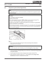
1
Descriptive Technical
Documentation
- Model-dependent -
DTD no. 511-6055
Model(s): PW 6055, PW 6065, PW 5065
15.06.2005, DE_en
This information should not be duplicated or passed on without Miele approval. All rights reserved.
This information should not be duplicated or passed on without Miele approval. All rights reserved.
15.06.2005, DE_en
Descriptive Technical Documentation
1
DTD no. 511-6055
Contents
General Information
A
Warning and Safety Instructions
B
Modification History
C
Technical Data
D
Layout of Electrical Components
Function Groups
030
Suds container, drum, bearings, heater element
1
2
Technical Data . . . . . . . . . . . . . . . . . . . . . . . . . . . . . . . . . . . . .
Function . . . . . . . . . . . . . . . . . . . . . . . . . . . . . . . . . . . . . . . . . . .
030-2
030-3
2.1
2.2
2.2.1
2.2.2
Heating . . . . . . . . . . . . . . . . . . . . . . . . . . . . . . . . . . . . . . . . . . . . . .
Foam sensing . . . . . . . . . . . . . . . . . . . . . . . . . . . . . . . . . . . . . . . . .
Excess foam when heating during the main wash . . . . . . . . . . . .
During rinse water intake excess foam is in the drum vent or
odour trap . . . . . . . . . . . . . . . . . . . . . . . . . . . . . . . . . . . . . . . . . . . .
During spinning excess foam is in the drum (water around drum
circumference registered) . . . . . . . . . . . . . . . . . . . . . . . . . . . . . . .
030-3
030-3
030-3
4
Service . . . . . . . . . . . . . . . . . . . . . . . . . . . . . . . . . . . . . . . . . . . . .
030-5
4.1
4.2
NTC temperature sensor, R30. . . . . . . . . . . . . . . . . . . . . . . . . . . .
Drum neck/suds container spacing gap setting . . . . . . . . . . . . . .
030-5
030-5
2.2.3
040
050
15.06.2005, DE_en
030-3
030-3
Water intake
2
Function . . . . . . . . . . . . . . . . . . . . . . . . . . . . . . . . . . . . . . . . . . .
040-2
2.1
2.2
2.3
2.4
2.5
2.6
Water path control unit and motor, M24 . . . . . . . . . . . . . . . . . . . .
Water intake monitoring . . . . . . . . . . . . . . . . . . . . . . . . . . . . . . . . .
Water overflow monitoring . . . . . . . . . . . . . . . . . . . . . . . . . . . . . . .
Alternative water. . . . . . . . . . . . . . . . . . . . . . . . . . . . . . . . . . . . . . .
External dispensing . . . . . . . . . . . . . . . . . . . . . . . . . . . . . . . . . . . .
External dispensing . . . . . . . . . . . . . . . . . . . . . . . . . . . . . . . . . . . .
040-2
040-2
040-2
040-2
040-3
040-4
4
Service . . . . . . . . . . . . . . . . . . . . . . . . . . . . . . . . . . . . . . . . . . . . .
040-5
4.1
4.2
Alternative water valve fitting . . . . . . . . . . . . . . . . . . . . . . . . . . . . .
Dispenser unit connection . . . . . . . . . . . . . . . . . . . . . . . . . . . . . . .
040-5
040-7
Drainage via drain valve
2
Function . . . . . . . . . . . . . . . . . . . . . . . . . . . . . . . . . . . . . . . . . . .
050-2
2.1
Drainage monitoring. . . . . . . . . . . . . . . . . . . . . . . . . . . . . . . . . . . .
050-2
This information should not be duplicated or passed on without Miele approval. All rights reserved.
Descriptive Technical Documentation
DTD no. 511-6055
2
060
070
080
Drainage via drain pump
2
Function . . . . . . . . . . . . . . . . . . . . . . . . . . . . . . . . . . . . . . . . . . .
060-2
2.1
Drainage monitoring. . . . . . . . . . . . . . . . . . . . . . . . . . . . . . . . . . . .
060-2
3-phase motor
1
3
Technical Data . . . . . . . . . . . . . . . . . . . . . . . . . . . . . . . . . . . . .
Fault Repair . . . . . . . . . . . . . . . . . . . . . . . . . . . . . . . . . . . . . . . .
070-2
070-3
3.1
Drive failure. . . . . . . . . . . . . . . . . . . . . . . . . . . . . . . . . . . . . . . . . . .
070-3
Fascia panel, control module
2
Function . . . . . . . . . . . . . . . . . . . . . . . . . . . . . . . . . . . . . . . . . . .
080-2
2.1
2.2
2.3
2.4
2.5
2.6
2.7
2.8
2.9
2.10
2.11
2.12
2.13
2.14
Reset signal for payment system . . . . . . . . . . . . . . . . . . . . . . . . .
Time of day programmable function . . . . . . . . . . . . . . . . . . . . . . .
Free spin programmable function . . . . . . . . . . . . . . . . . . . . . . . . .
Language programmable function . . . . . . . . . . . . . . . . . . . . . . . .
Payment system programmable function . . . . . . . . . . . . . . . . . . .
Operator code programmable function . . . . . . . . . . . . . . . . . . . . .
Max. speed programmable function . . . . . . . . . . . . . . . . . . . . . . .
Imbalance level programmable function. . . . . . . . . . . . . . . . . . . .
Heater rating programmable function . . . . . . . . . . . . . . . . . . . . . .
Heating programmable function . . . . . . . . . . . . . . . . . . . . . . . . . .
Temperature reduction programmable function . . . . . . . . . . . . . .
Control programmable function. . . . . . . . . . . . . . . . . . . . . . . . . . .
Drum lighting programmable function. . . . . . . . . . . . . . . . . . . . . .
Standard settings programmable function . . . . . . . . . . . . . . . . . .
Fault Repair . . . . . . . . . . . . . . . . . . . . . . . . . . . . . . . . . . . . . . . .
Demonstration mode . . . . . . . . . . . . . . . . . . . . . . . . . . . . . . . . . . .
Fault indication: Lamp defective . . . . . . . . . . . . . . . . . . . . . . . . .
Fault indication: Technical fault . . . . . . . . . . . . . . . . . . . . . . . . . .
F 0, no fault . . . . . . . . . . . . . . . . . . . . . . . . . . . . . . . . . . . . . . . . . . .
Fault code F 1, water/heating NTC sensor short-circuited. . . . . .
Fault code F 2, water/heating NTC sensor . . . . . . . . . . . . . . . . . .
Fault code F10, cold water intake . . . . . . . . . . . . . . . . . . . . . . . . .
Fault code F11, water drainage . . . . . . . . . . . . . . . . . . . . . . . . . . .
Fault code F15, hot water intake . . . . . . . . . . . . . . . . . . . . . . . . . .
Fault code F16, excess foam. . . . . . . . . . . . . . . . . . . . . . . . . . . . .
Fault code F20, heating . . . . . . . . . . . . . . . . . . . . . . . . . . . . . . . . .
Fault code F41, faulty EEPROM / data fault . . . . . . . . . . . . . . . . .
Fault code F43, model type not programmed. . . . . . . . . . . . . . . .
Fault code F44, I2C bus connection faulty . . . . . . . . . . . . . . . . . .
Fault code F45, faulty flash RAM / incorrect data . . . . . . . . . . . .
Fault code F46, display fault . . . . . . . . . . . . . . . . . . . . . . . . . . . . .
Fault code F47, selection module (EW) – Power-programme
module (ELP) interface fault . . . . . . . . . . . . . . . . . . . . . . . . . . . . .
Fault code F50, drive fault . . . . . . . . . . . . . . . . . . . . . . . . . . . . . . .
Fault code F51, pressure sensor . . . . . . . . . . . . . . . . . . . . . . . . . .
Fault code F53, tachogenerator . . . . . . . . . . . . . . . . . . . . . . . . . .
Fault code F56, no spin . . . . . . . . . . . . . . . . . . . . . . . . . . . . . . . . .
Fault code F63, water path control unit. . . . . . . . . . . . . . . . . . . . .
Fault code F65, drum lighting cap missing . . . . . . . . . . . . . . . . . .
080-2
080-2
080-2
080-3
080-3
080-3
080-4
080-4
080-4
080-4
080-4
080-5
080-5
080-5
3
3.1
3.2
3.3
3.4
3.5
3.6
3.7
3.8
3.9
3.10
3.11
3.12
3.13
3.14
3.15
3.16
3.17
3.18
3.19
3.20
3.21
3.22
3.23
This information should not be duplicated or passed on without Miele approval. All rights reserved.
080-6
080-6
080-6
080-7
080-8
080-8
080-9
080-9
080-11
080-12
080-13
080-14
080-14
080-15
080-15
080-16
080-16
080-16
080-17
080-17
080-18
080-19
080-19
080-20
15.06.2005, DE_en
Descriptive Technical Documentation
3
DTD no. 511-6055
090
15.06.2005, DE_en
4
Service . . . . . . . . . . . . . . . . . . . . . . . . . . . . . . . . . . . . . . . . . . . . . 080-21
4.1
4.2
4.3
4.4
4.5
4.6
Programming mode summary. . . . . . . . . . . . . . . . . . . . . . . . . . . .
Programming mode summary. . . . . . . . . . . . . . . . . . . . . . . . . . . .
Demonstration mode activation / deactivation . . . . . . . . . . . . . . .
Demonstration mode activation / deactivation . . . . . . . . . . . . . . .
Service mode summary. . . . . . . . . . . . . . . . . . . . . . . . . . . . . . . . .
Service mode summary. . . . . . . . . . . . . . . . . . . . . . . . . . . . . . . . .
080-21
080-25
080-29
080-30
080-31
080-35
Electrical components
2
Function . . . . . . . . . . . . . . . . . . . . . . . . . . . . . . . . . . . . . . . . . . .
090-2
2.1
2.2
2.3
Payment system socket (X1/1) . . . . . . . . . . . . . . . . . . . . . . . . . . .
Payment system . . . . . . . . . . . . . . . . . . . . . . . . . . . . . . . . . . . . . . .
Central control via RS 232 interface with 9-pole plug . . . . . . . . .
090-2
090-2
090-3
4
Service . . . . . . . . . . . . . . . . . . . . . . . . . . . . . . . . . . . . . . . . . . . . .
090-4
4.1
4.2
4.3
4.4
4.5
Working on frequency converter electronic unit (EFU) . . . . . . . .
Fitting payment system on machine lid. . . . . . . . . . . . . . . . . . . . .
Payment system (programme operation) . . . . . . . . . . . . . . . . . . .
Payment system (timed operation) . . . . . . . . . . . . . . . . . . . . . . . .
Central control via RS 232 interface . . . . . . . . . . . . . . . . . . . . . . .
090-4
090-4
090-6
090-7
090-8
This information should not be duplicated or passed on without Miele approval. All rights reserved.
4
This information should not be duplicated or passed on without Miele approval. All rights reserved.
Descriptive Technical Documentation
DTD no. 511-6055
15.06.2005, DE_en
DTD no. 511-6055
Descriptive Technical Documentation
A-1
A
Warning and Safety Instructions
1
General information
Service and repair work should only be carried out by suitably qualified persons in
accordance with all appropriate local and national safety regulations.
Servicing, modification, testing and maintenance of electrical appliances should
only be carried out in accordance with all appropriate legal requirements, accident
prevention regulations and valid standards.
All regulations of the appropriate utility supply companies and standards relating
to safety (not limited to electrical safety) are to be complied with.
Before any service work is commenced, the machine must be disconnected from
the mains.
Even with the machine switched off, mains power may be applied to some
components.
A general visual check should always be carried out.
15.06.2005, DE_en
This information should not be duplicated or passed on without Miele approval. All rights reserved.
Descriptive Technical Documentation
DTD no. 511-6055
A-2
2
Risk of injury due to sharp edges
There may be a risk of injury due to sharp edges.
Protective gloves should be worn and the edge protection, Mat. no. 05057680,
should be used.
This information should not be duplicated or passed on without Miele approval. All rights reserved.
15.06.2005, DE_en
DTD no. 511-6055
3
Descriptive Technical Documentation
A-3
Risk of electric shock when working on frequency
converter electronic unit (EFU)
PW 6055, PW 6065
x
Danger!
A capacitor on the frequency converter electronic unit holds an electrical charge
with a potential difference of up to approx. 400 V, even after disconnection from
the mains.
After disconnection from the mains a discharge resistor connected in parallel
with the capacitor should discharge it within approx. 2 min.
For safety reasons before working on any of the frequency converter (EFU)
components it is essential to ensure that this discharge has in fact taken place.
15.06.2005, DE_en
This information should not be duplicated or passed on without Miele approval. All rights reserved.
Descriptive Technical Documentation
DTD no. 511-6055
A-4
4
Risk of electric shock when working on powerprogramme module (ELP) (control-power module)
PW 5065
x
Danger!
A capacitor on the power-programme module (ELP) holds an electrical charge
with a potential difference of up to approx. 400 V, even after disconnection from
the mains.
After disconnection from the mains a discharge resistor connected in parallel
with the capacitor should discharge it within approx. 2 min.
For safety reasons before working on any of the power-programme module
(ELP) components it is essential to ensure that this discharge has in fact taken
place.
This information should not be duplicated or passed on without Miele approval. All rights reserved.
15.06.2005, DE_en
DTD no. 511-6055
5
Descriptive Technical Documentation
A-5
Electrical connection via plug connector
It is always recommended to make electrical connection via a plug and socket so
that electrical safety checks, e.g. during repair or service work, can be carried out
easily.
The socket must be accessible after machine installation. This also applies even
if an on-site mains switch is also already provided.
Models with a total connected load greater than 9 kW an additional on-site mains
switch must also be provided.
Electrical connection must be carried out in accordance with all appropriate legal
requirements, accident prevention regulations and valid standards.
15.06.2005, DE_en
This information should not be duplicated or passed on without Miele approval. All rights reserved.
Descriptive Technical Documentation
DTD no. 511-6055
A-6
6
Touch current measurement
x
Note
Touch current measurement should be carried out on all accessible conductive
parts that are not connected to earth.
Warning!
Touch current measurement should only be carried out after the earth
connection of the unit under test has been checked and found to be satisfactory!
Dangerous voltages may exist on defective machines as well as on accessible
conductive parts that are not connected to earth!
Note
Touch current measurement should be carried out on the following accessible
conductive parts:
•
Door ring
This information should not be duplicated or passed on without Miele approval. All rights reserved.
15.06.2005, DE_en
Descriptive Technical Documentation
B-1
DTD no. 511-6055
B
15.06.2005, DE_en
Modification History
When?
Who?
What?
11.05.2005
Olaf Meyer zu Drer
Initial compilation
This information should not be duplicated or passed on without Miele approval. All rights reserved.
B-2
This information should not be duplicated or passed on without Miele approval. All rights reserved.
Descriptive Technical Documentation
DTD no. 511-6055
15.06.2005, DE_en
Descriptive Technical Documentation
C-1
DTD no. 511-6055
C
Technical Data
Semi-commercial machines
PW 6055 and PW 6065
Casing, front
panel
Version
Generation 2000, spaceframe construction
Door lock
Electromagnetic release
Suds container
Suds container unit
Old suds container unit (ASA/OSU)
Water path
PW 5065
Drum
Honeycomb drum
Drum diameter
480 mm
Maximum load, dry laundry
5.5 kg / 6.5 kg
6.5 kg
Drum volume
5.5 kg: 54 l, 6.5 kg: 59 l
6.5 kg: 59 l
Drum opening dimensions
Large door opening 300 mm
Heating
2 x 2.65 kW, (5.3 kW, 2 N 16 A)
Water intake
Cold and hot water connection: Water path control unit
Alternative water supply valve
(can be retrofitted by Service
Dept.)
2 x 2.65 kW, (5.3 kW, 2 N 16 A)
-
Intake via door glass
Drainage
Drain valve (AV)
Synchronous drain pump (LP), head height 1 m
Drive
Belt drive
Ribbed drive belt, motor spindle diameter: 27.5 mm, axis-centre
difference: 345 mm, gearing (no. of motor rotations for one drum
rotation): 10.6
Electric motor
Commutator-free 3–phase asynchronous motor MXT 30
Speed monitoring
Tachogenerator -16-pole
Control
Electronic frequency converter
EFU 003-A
Power-programme module (ELP)
(control-power module) with
integrated frequency converter
(FU light)
Graphic display, multifunction
selector
Graphic display, rotary selector
Distance between axes: 345 mm
Control technol- Control panel
ogy
Selection module
221 ID 922
191 ID 902
Power-programme module
ELP 220 ID 973
ELP 250-G ID 903
Control technology: Novotronic IV. Update feature via serial optical
PC interface on module
Wash technology
Process technology
Hydromatic IV E, stored in ELP,
programme update feature
available
Level monitoring
Analog pressure sensor (ADS) integrated on the power-programme
module (ELP)
Suds temperature sensor
NTC (R30)
Imbalance monitoring
Speed-imbalance recognition
Hydromatic IV E, stored in ELP,
programme update feature
available
Imbalance sensor
Payment system
Machine pre-fitted with connections for operation with payment
system
Dispensing system
Machine supplied with 4
dispenser relays for activating
external dispenser pumps
Machine supplied with 1
dispenser relay for activating 1
external dispenser pump
Table 1: Semi-commercial washing machine (KG-WA), Generation 2000
15.06.2005, DE_en
This information should not be duplicated or passed on without Miele approval. All rights reserved.
C-2
This information should not be duplicated or passed on without Miele approval. All rights reserved.
Descriptive Technical Documentation
DTD no. 511-6055
15.06.2005, DE_en
DTD no. 511-6055
D
Descriptive Technical Documentation
D-1
Layout of Electrical Components
PW 6055, PW 6065
x
Layout 1
15.06.2005, DE_en
This information should not be duplicated or passed on without Miele approval. All rights reserved.
Descriptive Technical Documentation
DTD no. 511-6055
D-2
1 (Y12)
2 (Y14)
- (Y6)
3 (M24)
4 (X3/1)
5 (1Z1)
6 (2Z1)
7 (1X3/4)
8 (2X3/4)
9 (1K1/1)
10 (2K1/1)
11 (X1/1)
P6
P8
12 (1N1)
13 (2N1)
14 (S4)
15 (H3/6)
16 (R2)
17 (R1)
18 (R30)
19 (3N1)
20 (M5)
21 (M8)
22 (Y26)
23 (A2)
Solenoid valve - Hot water
Solenoid valve - Cold water
Solenoid valve - Alternative water supply (can be retrofitted by
Service Dept.)
Motor - Water path control unit
Mains terminal strip
Interference suppressor
Interference suppressor
Terminal strip - Dispenser system
Terminal strip - Dispenser system
Heating relay
Heating relay
Payment system socket
Payment system – Programme unit
Payment system – Time unit
Power-programme module (ELP) (control-power module)
Selection module (EW)
Switch - Door
Light - Drum
Heater element
Heater element
NTC temperature sensor
Frequency converter (EFU)
Motor - Drum drive
Drain pump (optional)
Drain valve (optional)
Door lock
This information should not be duplicated or passed on without Miele approval. All rights reserved.
15.06.2005, DE_en
DTD no. 511-6055
Descriptive Technical Documentation
D-3
PW 5065
x
Layout 2
15.06.2005, DE_en
This information should not be duplicated or passed on without Miele approval. All rights reserved.
Descriptive Technical Documentation
DTD no. 511-6055
D-4
1 (Y12)
2 (Y14)
3 (M24)
4 (X3/1)
5 (1Z1)
6 (2Z1)
7 (X3/4)
8 (1K1/1)
9 (2K1/1)
10 (X1/1)
P6
P8
11 (1N1)
12 (2N1)
13 (S4)
14 (H3/6)
15 (R2)
16 (R1)
17 (R30)
18 (M5)
19 (M8)
20 (Y26)
21 (A2)
Solenoid valve - Hot water
Solenoid valve - Cold water
Motor - Water path control unit
Mains terminal strip
Interference suppressor
Interference suppressor
Terminal strip - Dispenser system
Heating relay
Heating relay
Payment system socket
Payment system – Programme unit
Payment system – Time unit
Power-programme module (ELP) (control-power module)
Selection module (EW)
Switch - Door
Light - Drum
Heater element
Heater element
NTC temperature sensor
Motor - Drum drive
Drain pump (optional)
Drain valve (optional)
Door lock
This information should not be duplicated or passed on without Miele approval. All rights reserved.
15.06.2005, DE_en
DTD no. 511-6055
030
Descriptive Technical Documentation
030-1
Suds container, drum, bearings, heater element
x
15.06.2005, DE_en
This information should not be duplicated or passed on without Miele approval. All rights reserved.
Descriptive Technical Documentation
DTD no. 511-6055
030-2
1
Technical Data
Temperature (°C)
Resistance (kΩ)
0
38.0
5
29.7
10
23.4
15
18.6
20
14.9
25
12.0
30
9.73
35
7.96
40
6.55
45
5.42
50
4.52
55
3.78
60
3.19
65
2.70
70
2.29
75
1.96
80
1.68
85
1.45
90
1.25
93
1.15
95
1.09
100
1.06
Table 1: Temperature sensor (NTC, R30) - Resistance values
This information should not be duplicated or passed on without Miele approval. All rights reserved.
15.06.2005, DE_en
DTD no. 511-6055
2
Function
2.1
Heating
Descriptive Technical Documentation
030-3
Overheating protection:
To protect the machine against overheating in case of a technical fault, e.g. if the
heating relay contacts fuse together, the heater element has an overheating
protection device.
If the overheating device trips, the heater element is destroyed and must be
replaced.
2.2
Foam sensing
2.2.1
Excess foam when heating during the main wash
Foam is produced when the suds are heated. When the foam enters the
ventilation system, the pressure in the suds container increases.
If, during heating, the analog pressure sensor registers an increase in pressure of
60 mm wc (mm water column) above washing level, the following occurs:
– The heating is switched off for 2 min. After this time, it is only switched on
again when the pressure increase has dropped to 15 mm wc above washing
level. The fact that the desired temperature may not have been reached is not
indicated as a fault.
– If excess foam is registered 3 times, the Thermostop step is skipped.
– At the end of the programme, the display shows Check dispensing.
– The fault indication F16 Excess foam is saved, see Fault code F16, excess
foam, 080 3.10.
2.2.2
During rinse water intake excess foam is in the drum vent or odour trap
If excess foam exists during rinsing, then during water intake the pressure in the
suds container rises more rapidly than it would due merely to the incoming water.
If, during rinse water intake, the analog pressure sensor registers an increase in
pressure of 40 mm wc within 4 s, the following occurs:
– The water intake is switched off for at least 15 s.
– After this time, it is only switched on again when the pressure increase has
dropped to 15 mm wc.
– At the end of the programme, the display shows Check dispensing.
– The fault indication F16 Excess foam is saved, see Fault code F16, excess
foam, 080 3.10.
15.06.2005, DE_en
This information should not be duplicated or passed on without Miele approval. All rights reserved.
Descriptive Technical Documentation
DTD no. 511-6055
030-4
2.2.3
During spinning excess foam is in the drum (water around drum
circumference registered)
During spinning foam is produced and, due to centrifugal force, collects as water
around the drum circumference. The pressure increases and the water acts as a
brake on the drum.
If, during spinning, the analog pressure sensor registers a higher than expected
pressure for the spin speed in operation or the desired/actual speed variation is
greater than expected, the following occurs:
– The spin speed is reduced or the spin cycle is interrupted.
– If a spin above 700 rpm has not been carried out for a period of at least 60 s,
an additional rinse is activated.
– At the end of the programme, the display shows Check dispensing.
– The fault indication F16 Excess foam is saved, see Fault code F16, excess
foam, 080 3.10.
This information should not be duplicated or passed on without Miele approval. All rights reserved.
15.06.2005, DE_en
Descriptive Technical Documentation
030-5
DTD no. 511-6055
4
Service
4.1
NTC temperature sensor, R30
x
Danger!
Risk of electric shock when working on low-voltage components.
There is no circuit isolation between the power-programme module (ELP) and
mains voltage.
When working on a machine connected to the mains, the possible application of
mains potential to low-voltage components (e.g. NTC) must be taken into
consideration.
4.2
Drum neck/suds container spacing gap setting
x
Note
The drum neck/suds container spacing gap must be set precisely to prevent the
drum neck rubbing against the door seal during operation.
Note
Initial requirements:
– Drum, suds container, suds container cap and weights all pre-assembled.
– Pulley wheel secured on drive shaft.
– Motor bracket not secured.
15.06.2005, DE_en
This information should not be duplicated or passed on without Miele approval. All rights reserved.
Descriptive Technical Documentation
DTD no. 511-6055
030-6
Fig. 1
1
2
3
4
5
Pulley wheel
Drum bearing cross
Drum
Suds container
Centring tool, Mat. no. 05754630
A Loosen the bearing cross fixing screws by 2 turns.
A Fit the centring tool for drum and suds container with large door opening
(300 mm) on the suds container opening.
A Tip the complete suds container unit downwards and rest it on the centring
tool.
A Press down the suds container so its cap fully rests on the centring tool all
around the circumference.
A Press down the bearing cross so the drum opening fully rests on the centring
tool all around the circumference.
A Tighten the bearing cross fixing screws.
A Remove the centring tool.
This information should not be duplicated or passed on without Miele approval. All rights reserved.
15.06.2005, DE_en
Descriptive Technical Documentation
030-7
DTD no. 511-6055
x
Fig. 2
1
2
Suds container cap
Drum
A Check the desired gap dimension: 2 +1 mm.
15.06.2005, DE_en
This information should not be duplicated or passed on without Miele approval. All rights reserved.
030-8
This information should not be duplicated or passed on without Miele approval. All rights reserved.
Descriptive Technical Documentation
DTD no. 511-6055
15.06.2005, DE_en
DTD no. 511-6055
040
Descriptive Technical Documentation
040-1
Water intake
x
15.06.2005, DE_en
This information should not be duplicated or passed on without Miele approval. All rights reserved.
Descriptive Technical Documentation
DTD no. 511-6055
040-2
2
Function
2.1
Water path control unit and motor, M24
Driven via 230 V motor. Water path control unit position established via slip
contacts and time measurement.
2.2
Water intake monitoring
Water Control System (WCS):
With water intake monitoring, a closed on-site tap, water pressure that is too low
or a major leak, e.g. due to a missing fluff filter, can be detected.
During water intake the pressure increase is monitored to ensure that a pressure
increase of 8 mm wc occurs within 75 s. If this is not registered, the programme is
cancelled and a Water intake fault is indicated.
Hot water/Alternative water only: With the programmable water intake option
Hot water/Alternative water activated, the fault is registered but the programme
is continued with cold water intake only.
2.3
Water overflow monitoring
If a water level of 220 mm wc is reached, the drain pump/valve is activated until
the level drops to 180 mm wc.
2.4
Alternative water
PW 6055, PW 6065
The alternative water intake is via the main wash compartment.
For retrofitting of alternative water supply valve, see Alternative water valve fitting,
040 4.1.
This information should not be duplicated or passed on without Miele approval. All rights reserved.
15.06.2005, DE_en
Descriptive Technical Documentation
040-3
DTD no. 511-6055
2.5
External dispensing
PW 6055, PW 6065
These machines are supplied pre-fitted with 4 dispenser relays for activating
external dispenser pumps.
x
Warning!
The total current drawn by all connected dispenser pumps must not exceed 4 A.
Each dispensing relay can be used to dispense one liquid agent.
The dispensing relays are activated in accordance with the Service Dept.
programmable functions set for external dispensing.
x
Dispensing relay
Relay 1
Relay 2
Relay 3
Relay 4
Normal
detergent
Chlorine
bleach with
programmes
> 60°C
Mild detergent
Fabric
conditioner
Pre-wash
Cottons, Minimum iron, Table
linen, Kitchen linen, Disinfection
120 s
120 s
Main wash
Cottons, Sluice, Disinfection,
120 s
120 s
Cottons, Minimum iron, Quick
120 s
wash, Outerwear, Shirts, Denim,
Pillows, Table linen, Kitchen
linen, Towels, Hygiene
Pre- and main wash Delicates, Silks, Woollens,
Curtains
Fabric conditioner
120 s
All programmes except Table
linen
120 s
Table 1
The first and second dispensing stages are followed by a 5 s flush of water.
The hoses for liquid agents are connected to the rear of the detergent dispenser
drawer.
For dispenser connection, see Dispenser unit connection, 040 4.2.
15.06.2005, DE_en
This information should not be duplicated or passed on without Miele approval. All rights reserved.
Descriptive Technical Documentation
DTD no. 511-6055
040-4
2.6
External dispensing
PW 5065
This machine is supplied with 1 dispenser relay for activating 1 external dispenser
pump.
x
Warning!
The total current drawn by the connected dispenser pump must not exceed 4 A.
The dispensing relay is activated in accordance with the Service Dept.
programmable function set for external dispensing at the start of the pre-wash/
main wash.
The first and second dispensing stages are followed by a 5 s flush of water.
The hose for liquid agent is connected to the rear of the detergent dispenser
drawer.
For dispenser connection, see Dispenser unit connection, 040 4.2.
This information should not be duplicated or passed on without Miele approval. All rights reserved.
15.06.2005, DE_en
Descriptive Technical Documentation
040-5
DTD no. 511-6055
4
Service
4.1
Alternative water valve fitting
PW 6055, PW 6065
A Remove the machine lid.
x
Warning!
Lay the electrical connections above the transverse strut so that they cannot be
damaged by the sharp edge underneath the strut.
Warning!
The components for hot water connection are specially designed to withstand
high temperatures. Therefore only these parts should be used for the hot water
connection.
Fig. 1
Note
“Left” and “right” in the following assume the machine is being viewed from the
front.
15.06.2005, DE_en
This information should not be duplicated or passed on without Miele approval. All rights reserved.
Descriptive Technical Documentation
DTD no. 511-6055
040-6
A Release the casing cover and remove it.
A Disconnect the hot water intake hose.
A Disconnect the plug connection from the hot water inlet valve (Y12).
A Unscrew the fixing screw from the hot water inlet valve (Y12).
A Transfer the hot water inlet valve (Y12) from the left to the right.
A Turn the Y-hose and refit it on the hot water inlet valve (Y12).
A Secure the hot water inlet valve (Y12) with its fixing screw.
A Reconnect the plug connection to the hot water inlet valve (Y12).
A Fit and secure the hot water intake hose on the hot water inlet valve (Y12).
x
Fig. 2
A Fit the alternative water valve (Y6). Secure it with its fixing screw.
A Connect the hose between the detergent dispenser and the alternative water
valve (Y6).
A Lay the electrical connection in the small top channel from the power–
programme module (ELP 1N1) to the alternative water valve (Y6). Secure it to
the wiring harness with cable ties and connect both plugs.
A Refit the machine lid.
This information should not be duplicated or passed on without Miele approval. All rights reserved.
15.06.2005, DE_en
Descriptive Technical Documentation
040-7
DTD no. 511-6055
A Set the programmable function main wash water and/or rinse water to the
option Alternative water supply.
A Fit and secure the alternative water supply hose to the alternative water valve
(Y6).
4.2
Dispenser unit connection
x
Note
With the PW 5065 one dispenser pump with a connection hose with inner
diameter, Di = 6 mm and outer diameter, Da = 9 mm can be connected.
With the PW 6055 and PW 6065 up to 4 dispenser pumps with hoses with
Di = 4 mm / Da = 6 mm can be connected. For particularly viscous agents, one
of the 4 pumps can be connected with a hose with Di = 6 mm / Da = 9 mm.
Warning!
Only the holes required for a specific application should be made in the machine
casing and detergent dispenser.
A Remove the detergent dispenser.
A Remove the detergent dispenser top part.
x
Fig. 3
A With the PW 5065 and with viscous liquid agent, remove the stub on the
detergent dispenser and drill a 19 mm dia. hole in the position.
A With the PW 6055 and PW 6065, if the single connection for viscous liquid
agent is not sufficient, drill out the large marked opening, diameter
28.5 - 30 mm, on the detergent dispenser.
A Secure the hose through-feed/s on the detergent dispenser.
x
Warning!
The hoses must not contact or otherwise interfere with the concertina hose
which could otherwise be damaged.
A Lay the hose/s to the detergent dispenser and close any unused holes on the
hose through-feed with stoppers. Tighten the hose through-feed nut/s.
15.06.2005, DE_en
This information should not be duplicated or passed on without Miele approval. All rights reserved.
Descriptive Technical Documentation
DTD no. 511-6055
040-8
x
Fig. 4
A Refit the detergent dispenser top part.
A Refit the detergent dispenser.
A Open the pre-punched opening/s in the rear casing for the hoses and
electrical connections as necessary.
x
Note
When opening the holes, ensure that the waste metal pieces do not fall into the
machine.
Fig. 5: Hose positioning
This information should not be duplicated or passed on without Miele approval. All rights reserved.
15.06.2005, DE_en
Descriptive Technical Documentation
040-9
DTD no. 511-6055
Fig. 6: Wiring positioning
A Fit the appropriate hose and wire through-feed parts on the rear casing.
x
Warning!
Take care to lay hoses and wires such that they cannot be damaged by sharp
edges.
Lay the electrical connections above the transverse strut so that they cannot be
damaged by the sharp edge underneath the strut.
A Secure the hose/s in the machine.
A Optional: Activate the detergent drawer opening lock.
A Lay the electrical connection between the dispenser terminal strip (1X3/4,
2X3/4) and the dispenser. Secure the wires in the machine with cable ties.
A Make the electrical connections to the dispenser unit in accordance with its
documentation and the washing machine wiring diagram.
x
Note
PW 6055 and PW 6065 only:
The voltage supply to the dispenser via the washing machine dispensing relay
can be either from the washing machine power supply (230 V) or the dispensing
relay can be used as a potential-free contact.
When connecting an external dispenser to an external voltage supply:
Disconnect the L-DOS (live, phase) plug from the dispenser terminal strip
(1X3/4), insulate it and tie it to the wiring harness.
Connect the plug from the common external power source to the socket on the
dispenser terminal strip (1X3/4). Take care with the phase order.
The outputs from the dispenser terminal strip (2X3/4) can be used as potentialfree contacts.
15.06.2005, DE_en
This information should not be duplicated or passed on without Miele approval. All rights reserved.
Descriptive Technical Documentation
DTD no. 511-6055
040-10
A PW 6055 and PW 6065: Set the external dispensing programmable option on
the washing machine, see Programming mode summary, 080 4.1 and 040 2.5
External dispensing.
A PW 5065: Set the external dispensing programmable option on the washing
machine, see Programming mode summary, 080 4.2 und 040 2.6 External
dispensing.
This information should not be duplicated or passed on without Miele approval. All rights reserved.
15.06.2005, DE_en
Descriptive Technical Documentation
050-1
DTD no. 511-6055
050
Drainage via drain valve
x
15.06.2005, DE_en
This information should not be duplicated or passed on without Miele approval. All rights reserved.
Descriptive Technical Documentation
DTD no. 511-6055
050-2
2
Function
2.1
Drainage monitoring
Drainage monitoring is as with drainage via a drain pump, see 060 2.1 Drainage
monitoring.
This information should not be duplicated or passed on without Miele approval. All rights reserved.
15.06.2005, DE_en
Descriptive Technical Documentation
060-1
DTD no. 511-6055
060
Drainage via drain pump
x
15.06.2005, DE_en
This information should not be duplicated or passed on without Miele approval. All rights reserved.
Descriptive Technical Documentation
DTD no. 511-6055
060-2
2
Function
2.1
Drainage monitoring
When the drain pump is activated, a check is made to ensure that after 150 s the
water level has dropped to 7 mm wc. If the level has not dropped sufficiently, the
programme is interrupted and the fault message Drainage fault is indicated.
This information should not be duplicated or passed on without Miele approval. All rights reserved.
15.06.2005, DE_en
DTD no. 511-6055
070
Descriptive Technical Documentation
070-1
3-phase motor
x
15.06.2005, DE_en
This information should not be duplicated or passed on without Miele approval. All rights reserved.
Descriptive Technical Documentation
DTD no. 511-6055
070-2
1
Technical Data
Special tool
Setting gauge for drive belt tensioning
Mat. no. 05997590
Drive belt fitting lever
Mat. no. 05057690
Table 1: Drive - Special tool
This information should not be duplicated or passed on without Miele approval. All rights reserved.
15.06.2005, DE_en
Descriptive Technical Documentation
070-3
DTD no. 511-6055
3
Fault Repair
3.1
Drive failure
Cause
Drive blocked.
Check drum and drive for free movement
A Turn the drum by hand.
A If the drum can be turned freely with the drive belt fitted, the drum and drive
are not blocked.
A If this is not the case, carry out the following checks:
A Remove the drive belt.
A Check the drum for free movement.
A Check the drive motor for free movement.
Cause
Tachogenerator defective.
Check the tachogenerator
x
Danger!
Risk of electric shock when working on low-voltage components.
There is no circuit isolation between the power-programme module (ELP) and
mains voltage.
When working on a machine connected to the mains, the possible application of
mains potential to low-voltage components must be taken into consideration.
Note
The motor plug pin allocation is shown on the wiring diagram.
The given values apply to measurements taken at room temperature (20°C).
A Turn the motor (turn the drum rapidly by hand) and measure the voltage at the
tachogenerator.
A Desired value for AC voltage at tachogenerator: Approx. 1 - 3 V.
15.06.2005, DE_en
This information should not be duplicated or passed on without Miele approval. All rights reserved.
Descriptive Technical Documentation
DTD no. 511-6055
070-4
A Check the tachogenerator for short circuit with the motor earth.
A Check that the magnets are secured properly on the motor shaft.
Cause
Motor winding temperature limiter defective.
Check the motor winding temperature limiter
A Disconnect the motor connection plug.
A Check the motor winding temperature limiter for continuity.
A Check the motor winding temperature limiter insulation for short-circuit with
the motor.
Cause
Motor winding defective.
Check the motor winding
A Measure the resistance of the motor windings.
A Desired resistance value for each motor winding measured at the motor plug
at room temperature (20°C): 7 Ω ± 1 Ω (with higher temperatures the
resistance may be up to 1.5-times higher).
A Permitted difference between individual measurements: < 0.5 Ω.
A Desired resistance between motor winding and motor earth: ∞ Ω (isolation).
Cause
Motor earth open-circuited.
Check the motor earth
A Measure the resistance between the motor plug earth pin and the motor
housing.
A Desired resistance figure: Zero.
Cause
Motor wiring harness defective.
This information should not be duplicated or passed on without Miele approval. All rights reserved.
15.06.2005, DE_en
Descriptive Technical Documentation
070-5
DTD no. 511-6055
Check the motor wiring harness
A Check the motor wiring harness and plug for visible signs of damage.
A To check intermittent faults, flex the wiring harness while checking between
different wires for short circuits.
A To check intermittent faults, flex the wiring harness while checking individual
wires for continuity.
15.06.2005, DE_en
This information should not be duplicated or passed on without Miele approval. All rights reserved.
070-6
This information should not be duplicated or passed on without Miele approval. All rights reserved.
Descriptive Technical Documentation
DTD no. 511-6055
15.06.2005, DE_en
DTD no. 511-6055
080
Descriptive Technical Documentation
080-1
Fascia panel, control module
x
15.06.2005, DE_en
This information should not be duplicated or passed on without Miele approval. All rights reserved.
Descriptive Technical Documentation
DTD no. 511-6055
080-2
2
Function
2.1
Reset signal for payment system
At the end of a programme in order to reset an external payment system the
machine provides a mains voltage signal for 5 s applied to the payment system
connection socket (X1/1), pin 7 (payment system contact).
During this time, it is not possible to open the door via the door switch (S4).
The reset signal is also provided under the following circumstances:
– Free programmes
– Programme interruption
– Technical fault
2.2
Time of day programmable function
This function is for the display.
2.3
Free spin programmable function
This programmable function is used to set whether the Spin programme is
provided free or at a charge.
The Drain programme is always free.
PW 6055 and PW 6065: Programming mode, see Programming mode summary,
080 4.1.
PW 5065: Programming mode, see Programming mode summary, 080 4.2.
This information should not be duplicated or passed on without Miele approval. All rights reserved.
15.06.2005, DE_en
Descriptive Technical Documentation
080-3
DTD no. 511-6055
2.4
Language programmable function
PW 6055, PW 6065
International:
Multilingual start screen, e.g. for multilingual countries and camp sites.
The desired language is selected before the basic programme menu and is
applicable for only one programme.
The Sort language programmable function is available to select and sort four
favourite languages for international installations.
2.5
Payment system programmable function
This is used to set the type of payment system. The appropriate operating
procedure is shown in the display.
For payment system details see 090 2.2 Payment system.
PW 6055 and PW 6065 only: For central control via RS 232 interface see 090 2.3
Central control via RS 232 interface with 9-pole plug.
2.6
Operator code programmable function
Option code not required (domestic use):
Domestic programmable functions are freely available.
Supervisor programmable functions are not accessible.
Option code required (supervisor):
Access to domestic and supervisor programmable functions via code entry.
The code is freely selectable. If the code is no longer known to the supervisor,
then it can be reset to 000 by resetting all programmable functions to the standard
settings.
15.06.2005, DE_en
This information should not be duplicated or passed on without Miele approval. All rights reserved.
Descriptive Technical Documentation
DTD no. 511-6055
080-4
2.7
Max. speed programmable function
PW 6055, PW 6065
This is used to set the maximum spin speed (1400 - 1600 rpm) for the Cottons
and Spin programmes.
2.8
Imbalance level programmable function
PW 6055, PW 6065
This is used to set the imbalance levels.
2.9
Heater rating programmable function
The heater rating PHz is required for the calculation of controlled energy
consumption.
2.10
Heating programmable function
With this programmable function the heating can be switched off if the machine is
being used as a hot water model.
Thermostop stages are then skipped
Heating will still take place in programmes which do not use the hot water intake
such as Woollens, Silks, Curtains and Proofing.
2.11
Temperature reduction programmable function
PW 6055, PW 6065
This is used to reduce the maximum suds temperature to 80°C with high-altitude
locations > 4000 m above sea level to prevent the suds boiling.
This information should not be duplicated or passed on without Miele approval. All rights reserved.
15.06.2005, DE_en
Descriptive Technical Documentation
080-5
DTD no. 511-6055
2.12
Control programmable function
PW 6055, PW 6065
For setting the type of control with or without direct selection buttons and countryspecific additional programmes.
2.13
Drum lighting programmable function
On models without drum lighting, the lighting function must be deactivated.
2.14
Standard settings programmable function
To reset all programmable functions to standard settings.
The code no. for accessing the supervisor level will be reset to 000.
15.06.2005, DE_en
This information should not be duplicated or passed on without Miele approval. All rights reserved.
Descriptive Technical Documentation
DTD no. 511-6055
080-6
3
Fault Repair
3.1
Demonstration mode
Symptom
No programme start, service and programming modes cannot be accessed.
Cause
The demonstration mode is active.
Remedy
A PW 6055 and PW 6065: Demonstration mode deactivation, see
Demonstration mode activation / deactivation, 080 4.3.
A PW 5065: Demonstration mode deactivation, see Demonstration mode
activation / deactivation, 080 4.4.
3.2
Fault indication: Lamp defective
Symptom
In normal operation mode the display shows Lamp defective.
Cause
Halogen bulb open-circuited (bulb defective).
The power-programme module (ELP) has registered an open circuit in the drum
lighting circuit.
The fault is not saved.
Remedy
A Check the halogen bulb and exchange it if necessary.
A Check the drum lighting circuit for continuity.
Cause
Halogen bulb short-circuited.
The power-programme module (ELP) has registered a short circuit in the drum
lighting circuit.
This information should not be duplicated or passed on without Miele approval. All rights reserved.
15.06.2005, DE_en
Descriptive Technical Documentation
080-7
DTD no. 511-6055
Remedy
A Check the halogen bulb and exchange it if necessary.
A Check the drum lighting circuit for short circuit.
3.3
Fault indication: Technical fault
Symptom
In normal operation mode the display shows Technical fault.
Fault code display.
The programme is interrupted, water intake is shut off and the drain pump
operates or the drain valve opens for 120 s.
Cause
The power-programme module (ELP) or selection module (EW) has registered a
technical fault.
The power-programme module (ELP) interrupts the programme.
The fault indicated is the reason for the programme interruption.
Remedy
A PW 6055 and PW 6065: Fault memory display, see Service mode summary,
080 4.5.
A PW 5065: Fault memory display, see Service mode summary, 080 4.6.
A Check the Mat. nos. to ensure that the correct power-programme module
(ELP) and selection module (EW) are fitted.
A Check the electrical connections between the power-programme module
(ELP) and selection module (EW).
15.06.2005, DE_en
This information should not be duplicated or passed on without Miele approval. All rights reserved.
Descriptive Technical Documentation
DTD no. 511-6055
080-8
3.4
F 0, no fault
Cause
No fault saved in the power-programme module (ELP) fault memory.
Remedy
A None required.
3.5
Fault code F 1, water/heating NTC sensor short-circuited
Symptom
In normal operation mode this fault is not indicated via the display.
The heating is switched off after approx. 10 s.
The programme continues without heating.
Hot water operation: The programme continues with cold water.
Cause
NTC temperature sensor (R30) or its connections short-circuited.
NTC temperature sensor (R30) check
A Check the NTC temperature sensor in the service mode.
A PW 6055 and PW 6065: Service mode, see Service mode summary, 080 4.5.
A PW 5065: Service mode, see Service mode summary, 080 4.6.
A Check the NTC temperature sensor and its connections for an open or short
circuit, and correct insulation.
A Check the NTC temperature sensor resistance, see 030 Table 1.
This information should not be duplicated or passed on without Miele approval. All rights reserved.
15.06.2005, DE_en
Descriptive Technical Documentation
080-9
DTD no. 511-6055
3.6
Fault code F 2, water/heating NTC sensor
Symptom
In normal operation mode this fault is not indicated via the display.
The heating is switched off after approx. 10 s.
The programme continues without heating.
Hot water operation: The programme continues with cold water.
Cause
NTC temperature sensor (R30) or its connections open-circuited.
NTC temperature sensor (R30) check
A Check the NTC temperature sensor in the service mode.
A PW 6055 and PW 6065: Service mode, see Service mode summary, 080 4.5.
A PW 5065: Service mode, see Service mode summary, 080 4.6.
A Check the NTC temperature sensor for an open or short circuit, and correct
insulation.
A Check the NTC temperature sensor resistance, see 030 Table 1.
3.7
Fault code F10, cold water intake
Symptom
In normal operation mode the display shows Water intake fault.
The programme is interrupted, water intake is shut off and the drain pump
operates or the drain valve opens for 120 s.
The water intake is monitored, see 040 2.2 Water intake monitoring.
Cause
The machine has a leak. The Water Control System (WCS) has closed the water
intake.
Remedy
A Close the on-site stopcock.
A Locate the leak and repair it.
15.06.2005, DE_en
This information should not be duplicated or passed on without Miele approval. All rights reserved.
Descriptive Technical Documentation
DTD no. 511-6055
080-10
Cause
On-site stopcock is closed.
Remedy
A Open the on-site stopcock.
Cause
Water intake filters clogged.
Remedy
A Clean the water intake filters.
Cause
Low on-site water pressure.
On-site water pressure check
A The flow pressure must be at least 1 bar (100 hPa). With the stopcock fully
open, at least 5 l water should flow from the tap within 15 s.
A If the on-site flow pressure is less than 1 bar, then it should be increased.
A If the on-site flow pressure cannot be increased, then low water pressure can
be programmed as an option (water intake extended).
A PW 6055 and PW 6065: Programming mode, see Programming mode
summary, 080 4.1.
A PW 5065: Programming mode, see Programming mode summary, 080 4.2.
Cause
Water inlet solenoid valve defective.
Remedy
A Check the water inlet solenoid valve.
This information should not be duplicated or passed on without Miele approval. All rights reserved.
15.06.2005, DE_en
Descriptive Technical Documentation
080-11
DTD no. 511-6055
3.8
Fault code F11, water drainage
Symptom
In normal operation mode the display shows Water drainage fault.
The programme is interrupted and the drain pump operates or the drain valve
opens for 120 s.
The water drainage is monitored, see 060 2.1 Drainage monitoring.
Cause
Drain pump version: Insufficient drainage.
Remedy
A Check fluff filter for blockages caused by foreign bodies.
A Check drain hose.
A Check non-return valve.
A Check drain pump venting and priming.
A Check drain pump for correct operation.
Cause
Drain valve version: Insufficient drainage.
Remedy
A Check drain valve for correct operation.
15.06.2005, DE_en
This information should not be duplicated or passed on without Miele approval. All rights reserved.
Descriptive Technical Documentation
DTD no. 511-6055
080-12
3.9
Fault code F15, hot water intake
PW 6055, PW 6065
Symptom
In normal operation mode this fault is not indicated via the display.
The programme continues with cold water.
The water intake is monitored, see 040 2.2 Water intake monitoring.
Cause
Hot water stopcock closed.
Remedy
A Open hot water stopcock.
Cause
Hot water intake filters clogged.
Remedy
A Clean the hot water intake filters.
Cause
Low on-site hot water pressure.
On-site hot water pressure check
A The flow pressure must be at least 1 bar (100 hPa). With the stopcock fully
open, at least 5 l water should flow from the tap within 15 s.
A If the on-site flow pressure is less than 1 bar, then it should be increased.
A If the on-site flow pressure cannot be increased, then low water pressure can
be programmed as an option (water intake extended).
A PW 6055 and PW 6065: Programming mode, see Programming mode
summary, 080 4.1.
A PW 5065: Programming mode, see Programming mode summary, 080 4.2.
This information should not be duplicated or passed on without Miele approval. All rights reserved.
15.06.2005, DE_en
Descriptive Technical Documentation
080-13
DTD no. 511-6055
Cause
Hot water inlet solenoid valve defective.
Remedy
A Check the hot water inlet solenoid valve.
3.10
Fault code F16, excess foam
Symptom
In normal operation mode at the end of the programme the display shows the
warning Excess detergent.
The water intake solenoid valve is switched off for certain periods of time.
The heating is switched off. Even though the desired temperature is not reached,
this fault is not indicated.
The Thermostop step is skipped.
The spin speed is reduced or the spin cycle is interrupted.
An additional rinse cycle is carried out.
For details of foam sensing, see 030 2.2 Foam sensing.
Cause
Excess foam due to too much detergent being dispensed.
Follow detergent manufacturer's recommendations
A Follow the detergent manufacturer's recommendations with regard to water
hardness and level of soiling.
Cause
Vent hose blocked resulting in higher pressure increase during water intake.
Remedy
A Clean vent hose.
Cause
Drainage fault.
Remedy
A Check drain pump / drain valve.
15.06.2005, DE_en
This information should not be duplicated or passed on without Miele approval. All rights reserved.
Descriptive Technical Documentation
DTD no. 511-6055
080-14
3.11
Fault code F20, heating
Symptom
In normal operation mode this fault is not indicated via the display.
Poor wash results.
The suds are not warmed.
Long programme times.
Cause
The selected temperature has not been reached before the Thermostop time has
elapsed.
The heating is defective.
Check the heating
A Check the heater element circuit for an open or short circuit, and correct
insulation.
3.12
Fault code F41, faulty EEPROM / data fault
Symptom
In normal operation mode the display shows Technical fault.
The solenoid valve is closed and the programme interrupted. The drain pump is
activated for 120 s.
Cause
Faulty EEPROM / data fault.
Remedy
A Exchange the power-programme module (ELP).
This information should not be duplicated or passed on without Miele approval. All rights reserved.
15.06.2005, DE_en
DTD no. 511-6055
3.13
Descriptive Technical Documentation
080-15
Fault code F43, model type not programmed
PW 6055, PW 6065
Symptom
In normal operation mode the display shows Technical fault.
Cause
The selection module (EW) and power-programme module (ELP) do not match.
Remedy
A Check the Mat. nos. to verify that the correct selection module (EW) and
power-programme module (ELP) are fitted.
3.14
Fault code F44, I2C bus connection faulty
PW 5065
Symptom
In normal operation mode the display shows Technical fault.
The solenoid valve is closed and the programme interrupted. The drain pump is
activated for 120 s.
Cause
Internal technical fault in the power-programme module (ELP).
Remedy
A Exchange the power-programme module (ELP).
15.06.2005, DE_en
This information should not be duplicated or passed on without Miele approval. All rights reserved.
Descriptive Technical Documentation
DTD no. 511-6055
080-16
3.15
Fault code F45, faulty flash RAM / incorrect data
PW 6055, PW 6065
Cause
Internal technical fault in the power-programme module (ELP).
Remedy
A Check the Mat. nos. to verify that the correct selection module (EW) and
power-programme module (ELP) are fitted.
A Use the reset programmable function to reset all standard settings. Then
reprogram all required programmable functions.
A Exchange the power-programme module (ELP).
3.16
Fault code F46, display fault
PW 6055, PW 6065
Cause
Internal display fault in the selection module (EW). LCD module display driver
defective.
Remedy
A Exchange the selection module (EW).
3.17
Fault code F47, selection module (EW) – Power-programme
module (ELP) interface fault
Cause
Selection module (EW) – Power-programme module (ELP) interface fault.
Remedy
A Check the electrical connection between the selection module (EW) and
power-programme module (ELP).
This information should not be duplicated or passed on without Miele approval. All rights reserved.
15.06.2005, DE_en
Descriptive Technical Documentation
080-17
DTD no. 511-6055
3.18
Fault code F50, drive fault
Symptom
In normal operation mode the display shows Technical fault.
No drive.
The solenoid valve is closed and the programme interrupted. The drain pump is
activated for 120 s.
Cause
Motor defective which causes the frequency converter to be defective.
Remedy
A Check the motor, see Drive failure, 070 3.1.
Cause
Frequency converter (FU) defective.
Remedy
A Exchange the frequency converter (FU).
3.19
Fault code F51, pressure sensor
Symptom
In normal operation mode the display shows Technical fault.
The solenoid valve is closed and the programme interrupted. The drain pump is
activated for 120 s.
Cause
Analog pressure sensor (ADS) fault.
x
Note
The pressure sensor is integrated in the power-programme module (ELP).
Remedy
A Check the pressure sensor in the service mode, see Service mode summary,
080 4.5.
15.06.2005, DE_en
This information should not be duplicated or passed on without Miele approval. All rights reserved.
Descriptive Technical Documentation
DTD no. 511-6055
080-18
3.20
Fault code F53, tachogenerator
Symptom
In normal operation mode the display shows Technical fault.
The drum or drive is blocked. The motor does not start or is switched off after
1.5 s.
An attempt is made to start the motor during two reversing phases.
In the spin cycle, the programme is interrupted immediately.
The drive may possibly function again after a cooling period.
The solenoid valve is closed and the programme interrupted. The drain pump is
activated for 120 s.
Cause
Tachogenerator defective.
The tachogenerator is not supplying any meaningful AC voltage to the powerprogramme module (ELP).
Check tachogenerator
A Check the tachogenerator, see Drive failure, 070 3.1.
Cause
Drive defective.
Via the tachogenerator the power-programme module (ELP) has registered a
major discrepancy between the desired drive speed and actual drive speed.
Remedy
A Check the drive, see Drive failure, 070 3.1.
This information should not be duplicated or passed on without Miele approval. All rights reserved.
15.06.2005, DE_en
Descriptive Technical Documentation
080-19
DTD no. 511-6055
3.21
Fault code F56, no spin
PW 6055, PW 6065
Symptom
Final spin speed < 400 rpm even though the desired speed is at least 450 rpm.
Fault registered via tachogenerator.
Cause
Final spin speed < 400 rpm even though the desired speed is at least 450 rpm.
Remedy
A Check dispensed quantities, see Fault code F16, excess foam, 080 3.10.
A Check the drive, see Drive failure, 070 3.1.
3.22
Fault code F63, water path control unit
Symptom
In normal operation mode the display shows Technical fault.
The solenoid valve is closed and the programme interrupted. The drain pump is
activated for 120 s.
Cause
Water path control system faulty.
The power-programme module (ELP) cannot register a valid position of the water
path control unit within approx. 80 s of it being switched on.
x
Note
Water intake monitoring is not active if a valid position of the water path control
unit cannot be registered.
Check the water path control system
A Check the water path control system circuit for an open or short circuit, and
correct insulation.
15.06.2005, DE_en
This information should not be duplicated or passed on without Miele approval. All rights reserved.
Descriptive Technical Documentation
DTD no. 511-6055
080-20
3.23
Fault code F65, drum lighting cap missing
Symptom
In normal operation mode the display shows Drum lighting.
The solenoid valve is closed and the programme interrupted. The drain pump is
activated for 120 s.
Cause
If no drum lighting is fitted, the drum lighting programmable function has been set
in error.
Set drum lighting programmable function to off.
A PW 6055 and PW 6065: Programming mode, see Programming mode
summary, 080 4.1.
A PW 5065: Programming mode, see Programming mode summary, 080 4.2.
Cause
The lamp cover is missing or incorrectly fitted.
The power-programme module (ELP) registers a closed drum lighting unit switch
(H 3/6).
Check the drum lighting unit
A Check that the cap of the drum lighting unit (H 3/6) is seated correctly.
A Check the drum lighting unit circuit (switch), see the wiring diagram.
This information should not be duplicated or passed on without Miele approval. All rights reserved.
15.06.2005, DE_en
Descriptive Technical Documentation
080-21
DTD no. 511-6055
4
Service
4.1
Programming mode summary
PW 6055, PW 6065
Initial requirements
A Finish or cancel any programme in operation, including the demonstration
mode.
A Open the door.
A Disconnect the suds temperature sensor (R30) plug from the powerprogramme module (ELP).
x
Note
When the suds temperature sensor (R30) plug is disconnected, the door cannot
be opened via the door switch (S4).
A If the international multilingual start screen is shown, select the desired
language.
Accessing
x
Note
After it is begun, the accessing procedure must be completed within 10 s.
A Press and hold the Start button.
A Close the door.
A As soon as the Start button flashes, release the Start button.
A Immediately press and release the Start button 5 times and at the 5th time
hold it pressed in until programmable functions are shown in the display.
Acknowledgement indicator
Successful accessing of the programming mode is indicated by rapid flashing
(5 Hz) of the Start button.
The display shows the Service Dept. programmable functions.
If the accessing procedure has been unsuccessful, the control automatically
reverts to the normal operating mode.
15.06.2005, DE_en
This information should not be duplicated or passed on without Miele approval. All rights reserved.
Descriptive Technical Documentation
DTD no. 511-6055
080-22
Options
The set option is indicated by a V next to it.
A Programmable function selection: Turn the multifunction selector switch to
mark the desired function and press the multifunction selector switch to
confirm the selection.
A Option selection: Turn the multifunction selector switch to mark the desired
option and press the multifunction selector switch to confirm the selection.
x
Note
Highlighted options are standard settings.
If an electronic module is supplied as a replacement part, the highlighted
options should be set to suit the machine in which the module is fitted!
Programmable function
Option
Language
Language for operating, programming and service modes
Sort language
To select and sort four favourite languages for international installations
Water plus
Raised water level in pre- and main wash
Additional rinse cycle in Cottons and Minimum iron
Raised water level in pre- and main wash and additional rinse cycle in
Cottons and Minimum iron
Suds cooling (reactivation)
Off
On: Cold water added at end of main wash for 40 s via main wash
compartment in programmes with temperatures from 70°C
Time of day see 080 2.2 Time of day
programmable function
24 h clock
12 h clock am/pm
No clock, 24 h Delay start
Supervisor level
Code modification
Display contrast
Standard contrast setting: Bar diagram level 4
Display brightness
Standard brightness setting: Bar diagram level 5
Stand-by
On: Display und backlight switched off automatically after 10 min
Not in programme in operation: Stand-by only before and after
programme but not while it is in operation
Memory
Off: Not active
Temperature
Celsius [°C]
On: Active
Fahrenheit [°F]
Language at start of accessing, see 080 2.4
Language programmable function
National
Intensive water plus
Off: Extras not available with setting: As on domestic machines
International, additional welcome menu (favourite languages)
On: Extras available with setting: As on domestic machines
Save
Off: Save option not available
On: Save option available. Favourite programmes can be allocated to
direct selection buttons.
Automatic load control
Off: Programme sequence is carried out assuming a full load is in the
machine
On: Active
This information should not be duplicated or passed on without Miele approval. All rights reserved.
15.06.2005, DE_en
Descriptive Technical Documentation
080-23
DTD no. 511-6055
Programmable function
Option
Water intake - Pre-wash
Cold
Hot with temperature selection ≥ 30°C
Water intake - Main wash
Cold
Hot with temperature selection ≥ 30°C
Alternative water supply
Water intake - Rinses
Cold
Hot, no cool down
Alternative water supply
Level - Cottons
Block parameter
+ 15 mm wc
+ 25 mm wc
+ 35 mm wc
Level - Minimum iron
Block parameter
+ 10 mm wc
+ 20 mm wc
+ 30 mm wc
Temperature - Pre-wash - Cottons
Block parameter
35°C
45°C
55°C
Wash time - Pre-wash
Block parameter
+ 6 min
+ 9 min
+ 12 min
Wash time - Cottons
Block parameter
+ 10 min
+ 20 min
+ 30 min
+ 40 min
Wash time - Minimum iron
Block parameter
+ 5 min
+ 10 min
+ 15 min
+ 20 min
No. of programmes
0 additional programmes
4 additional programmes (Kitchen linen, Table linen, Curtains,
Pillows)
2 additional programmes (Outerwear, Proofing)
6 additional programmes (Kitchen linen, Table linen, Curtains,
Pillows, Outerwear, Proofing)
Hygiene
Off: Hygiene programme not available with setting: As on domestic
machines
On: Hygiene programme available with setting: As on domestic
machines
Sluice
Off: Without Sluice programmes
Disinfection
0 additional programmes
Pre-wash - Cottons
Menu selection
On: Both Sluice programmes available
4 additional programmes
Permanent
15.06.2005, DE_en
This information should not be duplicated or passed on without Miele approval. All rights reserved.
Descriptive Technical Documentation
DTD no. 511-6055
080-24
Programmable function
Option
2nd pre-wash - Kitchen linen
Off
On: Additional pre-wash in Kitchen linen
Controlled energy consumption
Off
On: In Cottons and Minimum iron
Rinses - Cottons
Rinses 1 + 5
Rinses 1 + 2 + 5
Rinses 1 + 2 + 3 + 5
Rinses 1 + 2 + 3 + 4 + 5
Rinses - Minimum iron
Rinses 1 + 4
Rinses 1 + 2 + 4
Rinses 1 + 2 + 3 + 4
Pre-rinse - Cottons
Off
On
Pre-rinse - Minimum iron
Off
On
Free spin, see 080 2.3 Free spin
programmable function
Off
External dispensing see 040 2.5 External
dispensing
Off
On
Pre-wash
Main wash
Pre-wash, main wash
No detergent
Off
On: An option to deactivate the dispensing relay is available with the
extras
Payment system operation, see 080 2.5
Payment system programmable function
Off (Delay start possible)
Programme operation
Timed operation
IK 6
RS 232 interface active
Supervisor level code, see 080 2.6 Operator
code programmable function
Code not required. Domestic programmable functions can be modified.
Max. spin speed, see 080 2.7 Max. speed
programmable function
1600 rpm
Code required. After code entry, domestic and supervisor
programmable functions can be modified.
1500 rpm
1400 rpm
Imbalance table, see 080 2.8 Imbalance level
programmable function
5.5 kg
Heater rating, see 080 2.9 Heater rating
programmable function
2100 W
6.5 kg
4200 W
2650 W
3000 W
4600 W
5300 W
Heating, see 080 2.10 Heating programmable
function
Off: No heating, no Thermostop
Temperature reduction, see 080 2.11
Temperature reduction programmable function
Off
On: Heating active, Thermostop active
On: Desired suds temperature ≥ 85°C limited to 80°C
This information should not be duplicated or passed on without Miele approval. All rights reserved.
15.06.2005, DE_en
Descriptive Technical Documentation
080-25
DTD no. 511-6055
Programmable function
Option
Control type, see 080 2.12 Control
programmable function
D As on domestic machines
CH As on domestic machines
GB Launderette
D Launderette
Drum lighting, see 080 2.13 Drum lighting
programmable function
Passive: If a washing machine is without drum lighting, the drum lighting
function must be deactivated.
Active
Standard setting
Reset all programmable functions to standard settings
Table 1: Programming mode summary
Save and quit
x
Note
Confirmed programmable options are saved.
A Reconnect the suds temperature sensor (R30) plug to the power-programme
module (ELP).
4.2
Programming mode summary
PW 5065
Initial requirements
A Finish or cancel any programme in operation, including the demonstration
mode.
A Open the door.
A Disconnect the suds temperature sensor (R30) plug from the powerprogramme module (ELP).
x
Note
When the suds temperature sensor (R30) plug is disconnected, the door cannot
be opened via the door switch (S4).
A During initial commissioning only: Select the desired language.
15.06.2005, DE_en
This information should not be duplicated or passed on without Miele approval. All rights reserved.
Descriptive Technical Documentation
DTD no. 511-6055
080-26
Accessing
x
Note
After it is begun, the accessing procedure must be completed within 10 s.
A Press and hold the Start button.
A Close the door.
A As soon as the Start LED flashes, release the Start button.
A Immediately press and release the Start button 5 times and at the 5th time
hold it pressed in until the Start LED flashes.
Acknowledgement indicator
Successful accessing of the programming mode is indicated by rapid flashing
(5 Hz) of the Start LED.
The display shows the Service Dept. programmable functions.
If the accessing procedure has been unsuccessful, the control automatically
reverts to the normal operating mode.
Options
A Programmable function selection: Press the + / - buttons as appropriate to
mark the desired function and press the OK button to confirm the selection.
The set option is indicated by a V next to it.
A Option selection: Press the + / - buttons as appropriate to mark the desired
option and press the OK button to confirm the selection.
x
Note
Highlighted options are standard settings.
If an electronic module is supplied as a replacement part, the highlighted
options should be set to suit the machine in which the module is fitted!
This information should not be duplicated or passed on without Miele approval. All rights reserved.
15.06.2005, DE_en
Descriptive Technical Documentation
080-27
DTD no. 511-6055
x
Programmable function
Option
Language
Language for operating, programming and service modes
Suds cooling (reactivation)
Off
On: Cold water added at end of main wash for 40 s via main wash
compartment in programmes with temperatures from 70°C
Time of day, see 080 2.2 Time of day
programmable function
24 h clock
12 h clock am/pm
No clock, 24 h Delay start
Supervisor level
Code modification
Display contrast
Standard contrast setting: Bar diagram level 4
Display brightness
Standard brightness setting: Bar diagram level 5
Stand-by
On: Display und backlight switched off automatically after 10 min
Not in programme in operation: Stand-by only before and after
programme but not while it is in operation
Memory
Off: Not active
On: Active
Automatic load control
Off: Programme sequence is carried out assuming a full load is in the
machine
On: Active
Water intake - Pre-wash
Cold
Hot with temperature selection ≥ 30°C
Water intake - Main wash
Cold
Hot with temperature selection ≥ 30°C
Water intake - Rinses
Cold
Hot, no cool down
Level - Cottons
Block parameter
+ 15 mm wc
+ 25 mm wc
+ 35 mm wc
Level - Minimum iron
Block parameter
+ 10 mm wc
+ 20 mm wc
+ 30 mm wc
Temperature - Pre-wash - Cottons
Block parameter
35°C
45°C
55°C
Wash time - Pre-wash
Block parameter
+ 6 min
+ 9 min
+ 12 min
Wash time - Cottons
Block parameter
+ 10 min
+ 20 min
+ 30 min
+ 40 min
15.06.2005, DE_en
This information should not be duplicated or passed on without Miele approval. All rights reserved.
Descriptive Technical Documentation
DTD no. 511-6055
080-28
Programmable function
Option
Wash time - Minimum iron
Block parameter
+ 5 min
+ 10 min
+ 15 min
+ 20 min
Pre-wash - Cottons
Menu selection
Permanent
List of special programmes
Standard setting 1
Standard setting 2
Bakers
Butchers
Hairdressers
Disinfection
Rinses - Cottons
Rinses 1 + 5
Rinses 1 + 2 + 5
Rinses 1 + 2 + 3 + 5
Rinses 1 + 2 + 3 + 4 + 5
Rinses - Minimum iron
Rinses 1 + 4
Rinses 1 + 2 + 4
Rinses 1 + 2 + 3 + 4
Pre-rinse - Cottons
Off
Pre-rinse - Minimum iron
Off
On
On
Free spin, see 080 2.3 Free spin
programmable function
Off
External dispensing, see 040 2.6 External
dispensing
Off
On
Pre-wash
Main wash
Pre-wash, main wash
Temperature
Celsius [°C]
Fahrenheit [°F]
Payment system operation, see080 2.5
Payment system programmable function
Off (Delay start possible)
Programme operation
Timed operation
Controlled energy consumption
Off
On: In Cottons and Minimum iron
Supervisor level code, see 080 2.6 Operator
code programmable function
Code not required. Domestic programmable functions can be modified.
Heater rating, see 080 2.9 Heater rating
programmable function
2100 W
Code required. After code entry, domestic and supervisor
programmable functions can be modified.
4200 W
2650 W
3000 W
4600 W
5300 W
Heating, see 080 2.10 Heating programmable
function
Off: No heating, no Thermostop
On: Heating active, Thermostop active
This information should not be duplicated or passed on without Miele approval. All rights reserved.
15.06.2005, DE_en
Descriptive Technical Documentation
080-29
DTD no. 511-6055
Programmable function
Option
Drum lighting, see 080 2.13 Drum lighting
programmable function
Passive: If a washing machine is without drum lighting, the drum lighting
function must be deactivated.
Active
Reset standard setting
Resets all programmable functions to standard settings
Table 2: Programming mode summary
Save and quit
x
Note
Confirmed programmable options are saved.
A Reconnect the suds temperature sensor (R30) plug to the power-programme
module (ELP).
4.3
Demonstration mode activation / deactivation
PW 6055, PW 6065
Initial requirements
A Finish or cancel any programme in operation.
A Open the door.
A If the international multilingual start screen is shown, select the desired
language.
Accessing
x
Note
After it is begun, the accessing procedure must be completed within 10 s.
A Press and hold the Start button.
A Close the door.
A As soon as the Start button lights up constantly, after approx. 5 s, release
the Start button.
x
Note
During deactivation the Start button does not light up constantly.
15.06.2005, DE_en
This information should not be duplicated or passed on without Miele approval. All rights reserved.
Descriptive Technical Documentation
DTD no. 511-6055
080-30
A Immediately press and hold the Start button until an appropriate instruction is
shown in the display (approx. 5 s).
A Follow the instruction shown in the display.
Acknowledgement indicator
The demonstration programme operates.
If the accessing procedure has been unsuccessful, the control automatically
reverts to the normal operating mode.
Options
The demonstration mode programme duration is approx. 90 s. After a short
pause, it starts again automatically.
x
Note
After an interruption in the mains supply, the demonstration mode programme
begins again automatically.
Save and quit
A Demonstration programme deactivation: Repeat the accessing procedure.
4.4
Demonstration mode activation / deactivation
PW 5065
Initial requirements
A Finish or cancel any programme in operation.
A Open the door.
Accessing
x
Note
After it is begun, the accessing procedure must be completed within 10 s.
A Press and hold the Start button.
A Close the door.
A As soon as the Start LED lights up constantly, after approx. 5 s, release the
Start button.
This information should not be duplicated or passed on without Miele approval. All rights reserved.
15.06.2005, DE_en
Descriptive Technical Documentation
080-31
DTD no. 511-6055
A Immediately press and hold the Start button until an appropriate instruction is
shown in the display (approx. 5 s).
A Follow the instruction shown in the display.
Acknowledgement indicator
The demonstration programme operates.
If the accessing procedure has been unsuccessful, the control automatically
reverts to the normal operating mode.
Options
The demonstration mode programme duration is approx. 90 s. After a short
pause, it starts again automatically.
x
Note
After an interruption in the mains supply, the demonstration mode programme
begins again automatically.
Save and quit
A Demonstration programme deactivation: Repeat the accessing procedure.
4.5
Service mode summary
PW 6055, PW 6065
Initial requirements
A Ensure the machine is installed and connected correctly.
A Finish or cancel any programme in operation, including the demonstration
mode.
A Open the door.
A If the international multilingual start screen is shown, select the desired
language.
Accessing
x
Note
After it is begun, the accessing procedure must be completed within 10 s.
15.06.2005, DE_en
This information should not be duplicated or passed on without Miele approval. All rights reserved.
Descriptive Technical Documentation
DTD no. 511-6055
080-32
A Press and hold the Start button.
A Close the door.
A As soon as the Start button flashes, release the Start button.
A Immediately press and release the Start button 3 times and at the 3rd time
hold it pressed in until service mode functions are shown in the display.
Acknowledgement indicator
Successful accessing of the service mode is indicated by slow flashing of the
Start button (1 Hz).
The display shows the service mode functions.
If the accessing procedure has been unsuccessful, the control automatically
reverts to the normal operating mode.
Options
A Service function selection: Turn the multifunction selector switch as
appropriate.
A Service function start and test step advance: Press the Start button.
x
Note
The service mode is switched off automatically 30 min after the last service
function has been checked.
This information should not be duplicated or passed on without Miele approval. All rights reserved.
15.06.2005, DE_en
Descriptive Technical Documentation
080-33
DTD no. 511-6055
Service function
Component / Sensor tested
Software version
Selection module (EW) ID no. Power-programme module (ELP) ID no.
Fault register
display1) and
deletion2)
15.06.2005, DE_en
Fault cause
Fault code
Remedy
No fault registered
F0
None required F 0, no fault, 080 3.4
Water/Heating NTC sensor
short-circuited
F1
See Fault code F 1, water/heating NTC sensor
short-circuited, 080 3.5
Water/Heating NTC sensor
open-circuited
F2
See Fault code F 2, water/heating NTC sensor,
080 3.6
Water intake fault – Cold water
F 10
See Fault code F10, cold water intake, 080 3.7
Drainage fault
F 11
See Fault code F11, water drainage, 080 3.8
Water intake fault – Hot water
F 15
See Fault code F15, hot water intake, 080 3.9
Excess foam
F 16
See Fault code F16, excess foam, 080 3.10
Heating fault (Thermostop
temperature not reached)
F 20
See Fault code F20, heating, 080 3.11
Faulty EEPROM / data fault
F 41
See Fault code F41, faulty EEPROM / data
fault, 080 3.12
Model type not programmed
F 43
See Fault code F43, model type not
programmed, 080 3.13
Flash fault
F 45
See Fault code F45, faulty flash RAM / incorrect
data, 080 3.15
Display fault
F 46
See Fault code F46, display fault, 080 3.16
Interface fault between EW /
ELP electronic modules
F 47
See Fault code F47, selection module (EW) –
Power-programme module (ELP) interface fault,
080 3.17
Drive fault
F 50
See Fault code F50, drive fault, 080 3.18
Pressure sensor fault
F 51
See Fault code F51, pressure sensor, 080 3.19
Tachogenerator fault (speed
sensor)
F 53
See Fault code F53, tachogenerator, 080 3.20
No spin
F 56
See Fault code F56, no spin, 080 3.21
Water path control unit fault
F 63
See Fault code F63, water path control unit,
080 3.22
Drum lighting cap missing
F 65
See Fault code F65, drum lighting cap missing,
080 3.23
This information should not be duplicated or passed on without Miele approval. All rights reserved.
Descriptive Technical Documentation
DTD no. 511-6055
080-34
Service function
Component
activation
Component / Sensor tested
Component activation
Function tested/Machine response
Water path control unit M 24
position 1 and Y14
Water intake via door glass for 10 s
Water path control unit M 24
position 2, solenoid valve Y14,
heating R1 + R2, analog
pressure sensor
Water intake via compartment I, until level I is reached.
Heating to 35°C then begins.
Water path control unit M 24
position 3, solenoid valve Y14,
analog pressure sensor
Water intake via compartment II, until level II is reached
Water path control unit M 24
position 4, solenoid valve Y14,
analog pressure sensor
Water intake via compartment III (fabric conditioner), until level
III is reached
Drain pump M8 / Drain valve
Y26
Drain pump M8 activated / Drain valve Y26 opened. Drainage
without level control.
Wash agitation, drum drive
motor M5
Drum rotation with reversing action
Spin drive, drum drive motor M5
Drain pump M8 activated / Drain valve Y26 opened, drum drive
motor M5 activated. Drainage and spinning depending on spin
speed selector setting.
Hot water valve Y12
Water intake via compartment II, until level III is reached
Drum lighting H3/6
Drum lighting on
Alternative water supply valve
Y6
Water intake via compartment II, until level III is reached
Dispensing relay 1M9
Dispenser relay activation
Dispensing relay 2M9
Dispenser relay activation
Dispensing relay 3M9
Dispenser relay activation
Dispensing relay 4M9
Dispenser relay activation
Programme end signal
Mains voltage applied to pin 7 of payment system socket (X1/1)
Sensor
State
Door contact (A2)
Door closed => Switch closed
Door open => Switch open
Sensor test
Payment system contact,
payment system socket (X1/1)
Connection wire bridge fitted between 1W14 pin 2/4 and
2W/14 pin 3/5
Connection wire bridge not fitted between 1W14 pin 2/4 and
2W/14 pin 3/5
Operating hours
counter display
Controls
Calibration
Power-programme module (ELP) Operating hours display
Buttons
Display indication for activated buttons
Display / LED test
All display points flash at the same time
Display background light
(backlight)
The backlight flashes on and off
Selection module (EW) test
See display for test results
Calibration not required as the machine does not have a load sensor
Table 3: Service mode summary
1)
If several faults are registered, their codes are shown one after the other in ascending order when the Start button is
pressed.
2)
Fault code deletion: Press the Start button for longer than 5 s during the fault code display (all stored fault codes are
deleted).
Quit (without saving)
A Open the door.
This information should not be duplicated or passed on without Miele approval. All rights reserved.
15.06.2005, DE_en
Descriptive Technical Documentation
080-35
DTD no. 511-6055
x
Note
Quitting from the calibration service function is not possible.
4.6
Service mode summary
PW 5065
Initial requirements
A Ensure the machine is installed and connected correctly.
A Finish or cancel any programme in operation, including the demonstration
mode.
A Open the door.
Accessing
x
Note
After it is begun, the accessing procedure must be completed within 10 s.
A Press and hold the Start button.
A Close the door.
A As soon as the Start LED flashes, release the Start button.
A Immediately press and release the Start button 3 times and at the 3rd time
hold it pressed in until the Start LED flashes slowly.
Acknowledgement indicator
Successful accessing of the service mode is indicated by slow flashing of the
Start LED (1 Hz).
The display shows the service mode functions.
If the accessing procedure has been unsuccessful, the control automatically
reverts to the normal operating mode.
Options
A Service function selection: Press the + / - buttons as appropriate.
A Service function start and test step advance: Press the OK button.
A Back to main level: Press the OK button.
15.06.2005, DE_en
This information should not be duplicated or passed on without Miele approval. All rights reserved.
Descriptive Technical Documentation
DTD no. 511-6055
080-36
x
Note
The service mode is switched off automatically 30 min after the last service
function has been checked.
Service function
Component / Sensor tested
Software version
Selection module (EW) ID no. Power-programme module (ELP) ID no.
Fault register
display1) and
deletion2)
Fault cause
Fault code
Remedy
No fault registered
F0
None required F 0, no fault, 080 3.4
Water/Heating NTC sensor
short-circuited
F1
See Fault code F 1, water/heating NTC sensor
short-circuited, 080 3.5
Water/Heating NTC sensor
open-circuited
F2
See Fault code F 2, water/heating NTC sensor,
080 3.6
Water intake fault – Cold water
F 10
See Fault code F10, cold water intake, 080 3.7
Drainage fault
F 11
See Fault code F11, water drainage, 080 3.8
Excess foam
F 16
See Fault code F16, excess foam, 080 3.10
Heating fault (Thermostop
temperature not reached)
F 20
See Fault code F20, heating, 080 3.11
Faulty EEPROM / data fault
F 41
See Fault code F41, faulty EEPROM / data
fault, 080 3.12
I2C bus connection faulty
F 44
See Fault code F44, I2C bus connection faulty,
080 3.14
Interface fault between EW /
ELP electronic modules
F 47
See Fault code F47, selection module (EW) –
Power-programme module (ELP) interface fault,
080 3.17
Drive fault
F 50
See Fault code F50, drive fault, 080 3.18
Pressure sensor fault
F 51
See Fault code F51, pressure sensor, 080 3.19
Tachogenerator fault (speed
sensor)
F 53
See Fault code F53, tachogenerator, 080 3.20
Water path control unit fault
F 63
See Fault code F63, water path control unit,
080 3.22
Drum lighting cap missing
F 65
See Fault code F65, drum lighting cap missing,
080 3.23
This information should not be duplicated or passed on without Miele approval. All rights reserved.
15.06.2005, DE_en
Descriptive Technical Documentation
080-37
DTD no. 511-6055
Service function
Component
activation
Component / Sensor tested
Component activation
Function tested/Machine response
Water path control unit M 24
position 1 and Y14
Water intake via door glass for 10 s
Water path control unit M 24
position 2, solenoid valve Y14,
heating R1 + R2, analog
pressure sensor
Water intake via compartment I, until level I is reached. Heating
to 35°C then begins.
Water path control unit M 24
position 3, solenoid valve Y14,
analog pressure sensor
Water intake via compartment II, until level II is reached
Water path control unit M 24
position 4, solenoid valve Y14,
analog pressure sensor
Water intake via compartment III (fabric conditioner), until level
III is reached
Drain pump M8 / Drain valve
Y26
Drain pump M8 activated / Drain valve Y26 opened. Drainage
without level control.
Wash agitation, drum drive
motor M5
Drum rotation with reversing action
Spin drive, drum drive motor M5
Drain pump M8 activated / Drain valve Y26 opened, drum drive
motor M5 activated. Drainage and spinning depending on spin
speed selector setting.
Hot water valve Y12
Water intake via compartment II, until level III is reached
Drum lighting H3/6
Drum lighting on
Dispensing relay 1M9
Dispenser relay activation
Programme end signal
Mains voltage applied to pin 7 of payment system socket (X1/1)
Sensor
State
Door contact (A2)
Door closed => Switch closed
Door open => Switch open
Sensor test
Payment system contact,
payment system socket (X1/1)
Connection wire bridge fitted between 1W14 pin 2/4 and 2W/14
pin 3/5
Connection wire bridge not fitted between 1W14 pin 2/4 and
2W/14 pin 3/5
Operating hours
counter display
Controls
Power-programme module (ELP) Operating hours display
Buttons
Display indication for activated buttons
Display / LED test
All display points flash at the same time
Display background light
(backlight)
The backlight flashes on and off
Rotary selector switch (DWS)
test
Programme positions: 0 - 21
Table 4: Service mode summary
1)
If several faults are registered, their codes are shown one after the other in ascending order when the Start button is
pressed.
2)
Fault code deletion: Press the Start button for longer than 5 s during the fault code display (all stored fault codes are
deleted).
Quit (without saving)
A Open the door.
15.06.2005, DE_en
This information should not be duplicated or passed on without Miele approval. All rights reserved.
080-38
This information should not be duplicated or passed on without Miele approval. All rights reserved.
Descriptive Technical Documentation
DTD no. 511-6055
15.06.2005, DE_en
Descriptive Technical Documentation
090-1
DTD no. 511-6055
090
Electrical components
x
15.06.2005, DE_en
This information should not be duplicated or passed on without Miele approval. All rights reserved.
Descriptive Technical Documentation
DTD no. 511-6055
090-2
2
Function
2.1
Payment system socket (X1/1)
x
Payment system socket (X1/1) - Washing machine side
Potential
Pin
Voltage supply switched by washing machine (ready for
operation signal)
L`
1
Start permitted by payment system
L`
2
Voltage supply direct for payment system
N
3
Voltage supply direct for payment system
L
4
Neutral switched by payment system
N`
5
Direct earth conductor
PE
6
Programme end signal
L`
7
Table 1: Payment system socket (X1/1) pin allocation
2.2
Payment system
The washing machine is pre-fitted with the requirements for operation in
conjunction with a payment system.
Three minutes after programme start, the door and programme are locked.
Payment system (programme operation):
The payment system provides the machine with a “start permitted” signal. After
the programme has been started, it continues without further influence from the
payment system.
For further details, see Payment system (programme operation), 090 4.3.
Payment system (timed operation):
The payment system provides the machine with a constant “operation permitted”
signal throughout the period of timed operation that has been purchased.
The programme continues so long as the signal is provided.
If the signal is interrupted, the programme and time left are stopped and the
machine components are switched off.
For further details, see Payment system (timed operation), 090 4.4.
This information should not be duplicated or passed on without Miele approval. All rights reserved.
15.06.2005, DE_en
Descriptive Technical Documentation
090-3
DTD no. 511-6055
2.3
Central control via RS 232 interface with 9-pole plug
PW 6055, PW 6065
Possible to use one central control/payment system.
Control data can be read and modified.
For further details, see Central control via RS 232 interface, 090 4.5.
15.06.2005, DE_en
This information should not be duplicated or passed on without Miele approval. All rights reserved.
Descriptive Technical Documentation
DTD no. 511-6055
090-4
4
Service
4.1
Working on frequency converter electronic unit (EFU)
PW 6055, PW 6065
x
Danger!
Risk of electric shock when working on frequency converter electronic unit
(EFU).
A capacitor on the frequency converter electronic unit holds an electrical charge
with a potential difference of up to approx. 400 V, even after disconnection from
the mains.
After disconnection from the mains a discharge resistor connected in parallel
with the capacitor should discharge it within approx. 2 min.
For safety reasons before working on any of the frequency converter (EFU)
components it is essential to ensure that this discharge has in fact taken place.
4.2
Fitting payment system on machine lid
A Remove the machine lid.
x
Fig. 1
Warning!
When drilling through the machine lid take care to not drill into the surface on
which it is resting!
A Drill 4 fixing holes through the machine lid in accordance with the payment
system template.
This information should not be duplicated or passed on without Miele approval. All rights reserved.
15.06.2005, DE_en
DTD no. 511-6055
Descriptive Technical Documentation
090-5
x
Fig. 2
A Place the plastic underlay on the machine lid. Secure the payment system to
the lid on the underlay using the screws, washers, retaining rings and nuts
provided.
x
Note
For further details, see Payment system (programme operation), 090 4.3,
Payment system (timed operation), 090 4.4.
A Refit the machine lid.
15.06.2005, DE_en
This information should not be duplicated or passed on without Miele approval. All rights reserved.
Descriptive Technical Documentation
DTD no. 511-6055
090-6
4.3
Payment system (programme operation)
x
Note
The instructions given in the documentation provided with the payment system
must be followed.
Fig. 3
A Open the pre-punched opening/s in the rear casing for the electrical
connections as necessary.
x
Warning!
Take care to lay wires such that they cannot be damaged by sharp edges.
A Fit the appropriate through-feed parts on the wires. Secure the through-feeds
on the rear casing.
A Lay the payment system wire to the payment system socket (X1/1).
A At the payment system socket (X1/1), cut through the wire bridge 1W14
between pins 2 and 4. Insulate the wire ends.
A PW 6055 and PW 6065: Set the payment system programmable option to
Programme operation, see Programming mode summary, 080 4.1.
A PW 5065: Set the payment system programmable option to Programme
operation, see Programming mode summary, 080 4.2.
A Fit the payment system on the machine lid, see Fitting payment system on
machine lid, 090 4.2.
This information should not be duplicated or passed on without Miele approval. All rights reserved.
15.06.2005, DE_en
Descriptive Technical Documentation
090-7
DTD no. 511-6055
4.4
Payment system (timed operation)
x
Note
The instructions given in the documentation provided with the payment system
must be followed.
Warning!
The connection has been modified.
Danger of short circuit.
When a time payment system C 5003 is fitted, the connection from pin 7 to
connection 2 on the payment system must be disconnected.
A bridge must be made in the payment system from connection 3 (operational
signal) to connection 2 (transformer).
With incorrect connection, connection from pin 7 to connection 2 on the payment
system not disconnected, a short circuit will exist at the end of the programme.
Check the wiring diagram.
Fig. 4
A Open the pre-punched opening/s in the rear casing for the electrical
connections as necessary.
x
Warning!
Take care to lay wires such that they cannot be damaged by sharp edges.
A Fit the appropriate through-feed parts on the wires. Secure the through-feeds
on the rear casing.
A Lay the payment system wire to the payment system socket (X1/1).
A At the payment system socket (X1/1), cut through the wire bridge 2W14
between pins 3 and 5. Insulate the wire ends.
15.06.2005, DE_en
This information should not be duplicated or passed on without Miele approval. All rights reserved.
Descriptive Technical Documentation
DTD no. 511-6055
090-8
A PW 6055 and PW 6065: Set the payment system programmable option to
Timed operation, see Programming mode summary, 080 4.1.
A PW 5065: Set the payment system programmable option to Timed
operation, see Programming mode summary, 080 4.2.
A Fit the payment system on the machine lid, see Fitting payment system on
machine lid, 090 4.2.
4.5
Central control via RS 232 interface
PW 6055, PW 6065
x
Danger!
Risk of electric shock due to voltage transfer with incorrectly laid data cables.
Note
The instructions given in the documentation provided with the central control
must be followed.
Warning!
Take care to lay wires such that they cannot be damaged by sharp edges.
A Remove the machine lid.
x
Fig. 5
This information should not be duplicated or passed on without Miele approval. All rights reserved.
15.06.2005, DE_en
DTD no. 511-6055
Descriptive Technical Documentation
090-9
Fig. 6
A Unscrew and remove the connection box lid. Loosen the cable strain relief.
A Pass the data cable through the casing opening for the mains connection
cable. Lay the data cable to the RS 232 interface on the power-programme
module (ELP).
A Connect the data cable plug to the RS 232 interface and secure it with the
screws.
A Fasten the data cable to the transverse strut with cable ties. Secure the data
cable in the strain relief together with the mains connection cable. Refit the
connection box lid.
A At the payment system socket (X1/1), cut either through the wire bridge 1W14
between pins 2 and 4 or the wire bridge 2W14 between pins 3 and 5 as
desired. Insulate the wire ends.
A At the washing machine, set the payment system programmable option to
RS 232, see Programming mode summary, 080 4.1.
15.06.2005, DE_en
This information should not be duplicated or passed on without Miele approval. All rights reserved.
090-10
This information should not be duplicated or passed on without Miele approval. All rights reserved.
Descriptive Technical Documentation
DTD no. 511-6055
15.06.2005, DE_en