1
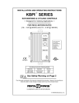
Installation and Operation Manual
KBMM™
FA+
L1
Surface Mount Technology
DECEL
L2
Solid State SCR
DC Motor Speed Controls
F+
J2
B
T
CL
for Use with 1/100 – 3 HP, 90 and 180 Volt
Permanent Magnet and Shunt Wound DC Motors*
ACCEL
P3
PWR ON
J1
CONN1
EN
AC Line Input: 115 and 208/230 Volts, 50/60 Hz
P2
A-
I1
P1
I2
This Manual Covers Models KBMM-125, 225, 225D
MIN
MAX
CL
IR
PATENTED
Ultra Fast Current Limit Circuit Prevents
Demagnetization in Permanent Magnet Motors
*
!
See Safety Warning on page 6.
*See page 6
for CE
Information
A Plug-In Horsepower Resistor® and AC Line
and Armature Fuses, supplied separately,
must be installed for this product to operate.
*Auxiliary Heat Sink (Part No. 9861) is required
to achieve maximum rating of control. See
Electrical Ratings, Table 1, on page 9.
The information contained in this manual is intended to be accurate. However, the manufacturer retains the right
to make changes in design which may not be included herein.
Manufactured
in the USA
A COMPLETE LINE OF MOTOR DRIVES
© 2004 KB Electronics, Inc.
(See back cover)
TABLE OF CONTENTS
Section
Page
1 Simplified Installation Instructions . . . . . . . . . . . . . . . . . . . . . . . . . . . . . . . . . . . . . . . . . . . . . . . . . . . . . . . . . . . . . 4
2 Safety Warning . . . . . . . . . . . . . . . . . . . . . . . . . . . . . . . . . . . . . . . . . . . . . . . . . . . . . . . . . . . . . . . . . . . . . . . . . . . 6
3 Introduction . . . . . . . . . . . . . . . . . . . . . . . . . . . . . . . . . . . . . . . . . . . . . . . . . . . . . . . . . . . . . . . . . . . . . . . . . . . . . . 7
4 Application Information . . . . . . . . . . . . . . . . . . . . . . . . . . . . . . . . . . . . . . . . . . . . . . . . . . . . . . . . . . . . . . . . . . . . 11
5 Mounting Instructions . . . . . . . . . . . . . . . . . . . . . . . . . . . . . . . . . . . . . . . . . . . . . . . . . . . . . . . . . . . . . . . . . . . . . 12
6 Wiring Instructions . . . . . . . . . . . . . . . . . . . . . . . . . . . . . . . . . . . . . . . . . . . . . . . . . . . . . . . . . . . . . . . . . . . . . . . 13
7 Setting Selectable Jumpers . . . . . . . . . . . . . . . . . . . . . . . . . . . . . . . . . . . . . . . . . . . . . . . . . . . . . . . . . . . . . . . . 19
8 AC Line and Armature Fusing . . . . . . . . . . . . . . . . . . . . . . . . . . . . . . . . . . . . . . . . . . . . . . . . . . . . . . . . . . . . . . . 20
9 Plug-In Horsepower Resistor® . . . . . . . . . . . . . . . . . . . . . . . . . . . . . . . . . . . . . . . . . . . . . . . . . . . . . . . . . . . . . . 21
10 Recommended High Voltage Dielectric Withstand Testing (Hi-Pot Testing) . . . . . . . . . . . . . . . . . . . . . . . . . . . . . 22
11 Trimpot Adjustments . . . . . . . . . . . . . . . . . . . . . . . . . . . . . . . . . . . . . . . . . . . . . . . . . . . . . . . . . . . . . . . . . . . . . . 24
12 Diagnostic LEDs . . . . . . . . . . . . . . . . . . . . . . . . . . . . . . . . . . . . . . . . . . . . . . . . . . . . . . . . . . . . . . . . . . . . . . . . . 28
13 Switching Circuits . . . . . . . . . . . . . . . . . . . . . . . . . . . . . . . . . . . . . . . . . . . . . . . . . . . . . . . . . . . . . . . . . . . . . . . . 28
14 Optional Accessories . . . . . . . . . . . . . . . . . . . . . . . . . . . . . . . . . . . . . . . . . . . . . . . . . . . . . . . . . . . . . . . . . . . . . 30
Limited Warranty . . . . . . . . . . . . . . . . . . . . . . . . . . . . . . . . . . . . . . . . . . . . . . . . . . . . . . . . . . . . . . . . . . . . . . . . . . . . 32
Tables
1 Electrical Ratings . . . . . . . . . . . . . . . . . . . . . . . . . . . . . . . . . . . . . . . . . . . . . . . . . . . . . . . . . . . . . . . . . . . . . . . . . 9
2 General Performance Specifications . . . . . . . . . . . . . . . . . . . . . . . . . . . . . . . . . . . . . . . . . . . . . . . . . . . . . . . . . . . 9
3 Minimum Supply Wire Size Requirements . . . . . . . . . . . . . . . . . . . . . . . . . . . . . . . . . . . . . . . . . . . . . . . . . . . . . . 13
4 Field Connection (Shunt Wound Motors Only) . . . . . . . . . . . . . . . . . . . . . . . . . . . . . . . . . . . . . . . . . . . . . . . . . . . 14
5 AC Line and Armature Fuse Selection . . . . . . . . . . . . . . . . . . . . . . . . . . . . . . . . . . . . . . . . . . . . . . . . . . . . . . . . . 21
6 Plug-In Horsepower Resistor® Selection . . . . . . . . . . . . . . . . . . . . . . . . . . . . . . . . . . . . . . . . . . . . . . . . . . . . . . 22
7 RFI Filter Selection . . . . . . . . . . . . . . . . . . . . . . . . . . . . . . . . . . . . . . . . . . . . . . . . . . . . . . . . . . . . . . . . . . . . . . . 31
2
TABLE OF CONTENTS (Continued)
Figures
Page
1 Control Layout and General Connection Diagram . . . . . . . . . . . . . . . . . . . . . . . . . . . . . . . . . . . . . . . . . . . . . . . . 10
2 Mechanical Specifications . . . . . . . . . . . . . . . . . . . . . . . . . . . . . . . . . . . . . . . . . . . . . . . . . . . . . . . . . . . . . . . . . . 11
3 Remote Main Speed Potentiometer Connection . . . . . . . . . . . . . . . . . . . . . . . . . . . . . . . . . . . . . . . . . . . . . . . . . 15
4 Voltage Following Connection . . . . . . . . . . . . . . . . . . . . . . . . . . . . . . . . . . . . . . . . . . . . . . . . . . . . . . . . . . . . . . . 15
5 Enable Switch or Contact Wired to the Enable Connector . . . . . . . . . . . . . . . . . . . . . . . . . . . . . . . . . . . . . . . . . 16
6 Enable Switch or Contact Wired to the Main Speed Potentiometer . . . . . . . . . . . . . . . . . . . . . . . . . . . . . . . . . . 17
7 Inhibit Switch or Contact Wired to the Inhibit Terminals . . . . . . . . . . . . . . . . . . . . . . . . . . . . . . . . . . . . . . . . . . . . 17
8 DC Tach-Generator Connection (7 Volts per 1000 RPM) . . . . . . . . . . . . . . . . . . . . . . . . . . . . . . . . . . . . . . . . . . 18
9 DC Tach-Generator Connection (50 Volts per 1000 RPM) . . . . . . . . . . . . . . . . . . . . . . . . . . . . . . . . . . . . . . . . . 18
10 Other DC Tach-Generator Connection (with Addition of RT) . . . . . . . . . . . . . . . . . . . . . . . . . . . . . . . . . . . . . . . . 19
11 AC Line Input Voltage Selection (Jumper J1 (Model KBMM-225D Only)) . . . . . . . . . . . . . . . . . . . . . . . . . . . . . . 20
12 Motor Voltage and DC Tach-Generator Selection (Jumper J2) . . . . . . . . . . . . . . . . . . . . . . . . . . . . . . . . . . . . . . 20
13 Hi-Pot Test Setup . . . . . . . . . . . . . . . . . . . . . . . . . . . . . . . . . . . . . . . . . . . . . . . . . . . . . . . . . . . . . . . . . . . . . . . . 23
14 Acceleration Trimpot (ACCEL) Range . . . . . . . . . . . . . . . . . . . . . . . . . . . . . . . . . . . . . . . . . . . . . . . . . . . . . . . . . 24
15 Deceleration Trimpot (DECEL) Range . . . . . . . . . . . . . . . . . . . . . . . . . . . . . . . . . . . . . . . . . . . . . . . . . . . . . . . . . 25
16 Minimum Speed Trimpot (MIN) Range . . . . . . . . . . . . . . . . . . . . . . . . . . . . . . . . . . . . . . . . . . . . . . . . . . . . . . . . . 25
17 Maximum Speed Trimpot (MAX) Range . . . . . . . . . . . . . . . . . . . . . . . . . . . . . . . . . . . . . . . . . . . . . . . . . . . . . . . . 25
18 Current Limit Trimpot (CL) Range . . . . . . . . . . . . . . . . . . . . . . . . . . . . . . . . . . . . . . . . . . . . . . . . . . . . . . . . . . . . 26
19 IR Compensation Trimpot (IR) Range . . . . . . . . . . . . . . . . . . . . . . . . . . . . . . . . . . . . . . . . . . . . . . . . . . . . . . . . . 27
20 Typical Dynamic Brake Circuit Connection . . . . . . . . . . . . . . . . . . . . . . . . . . . . . . . . . . . . . . . . . . . . . . . . . . . . . 29
Items Included in this package – KBMM™ Speed Control, KBMM™ Installation and Operation Manual, Hardware
Bag (contains Main Speed Potentiometer with insulator and mounting hardware, (9) – 0.25” female crimp-on terminals, (4) – 0.11” female crimp-on terminals, and an Enable harness), CE Approved Product Information Card, and
Warranty Registration Card.
Items required to operate this control – Plug-In Horsepower Resistor®, AC Line Fuse and Armature Fuse. Supplied
through your distributor. See Sections 8 and 9, on pages 20 - 22.
3
1
SIMPLIFIED INSTALLATION INSTRUCTIONS
IMPORTANT – Read these simplified installation instructions before proceeding. These instructions are to be
used as a reference only and are not intended to replace the detailed instructions provided herein. You must
read the Safety Warning, on page 6, before proceeding.
Note: A Plug-In Horsepower Resistor® and AC Line and
Armature Fuses, supplied separately, must be installed in
order for this product to operate. See Section 9, on page 21.
Fuse
Plug-In Horsepower
Resistor®
1.1 AC Line Connection – Wire the AC line to Terminals “L1” (Line Fuse) and “L2”, as shown in Figure 1, on
page 10 and as described in Section 6.1, on page 13.
Model KBMM-125 is rated for 115 Volt AC line input only. Model KBMM-225 is rated for 230 Volt AC line
input only. Model KBMM-225D is rated for 115 Volt AC line input (Jumper J1 in the “115” position) and 230
Volt AC line input (Jumper J1 in the “230” position). See Section 7.1, on page 19.
Notes: 1. The rated AC line voltage (115, 208/230) of the control must match the actual AC line input
voltage. 2. If one of the AC line inputs is a neutral (N), wire it to Terminal “L2”.
1.2 Ground Connection – Connect the ground wire (earth) to the control chassis.
1.3 Motor Connection – Connect the motor to Terminals “A+” (Armature Fuse) and “A-”, as shown in Figure 1,
on page 10, and as described in Section 6.3, on page 14.
1.4 Jumper Settings – Jumper J1 (on Model KBMM-225D only) and Jumper J2 (all models) have been factory
set for most applications, as shown in Figure 1, on page 10, and as described in Section 7, on page 19.
4
1.5 AC line Fusing – It is required that an AC line fuse (supplied separately) be installed in the AC Line Fuse
Holder, as shown in Figure 1, on page 10. Select the correct AC Line Fuse, as described in Section 8, on
pages 20 and 21. Fuse each conductor that is not at ground potential.
1.6 Armature Fusing – It is required that an Armature Fuse (supplied separately) be installed in the Armature
Fuse Holder, as shown in Figure 1, on page 10. Select the correct Armature Fuse as described in Section 8,
on pages 20 and 21.
1.7 Plug-In Horsepower Resistor® – Install the correct Plug-In Horsepower Resistor® according to armature
voltage and motor horsepower, as shown in Figure 1, on page 10. Select the correct Plug-In Horsepower
Resistor®, as described in Section 9, on pages 21 and 22.
1.8 Trimpot Settings – All trimpots have been factory set for most applications, as shown in Figure 1, on page
10. The trimpots may be readjusted, as described in Section 11, on page 24.
1.9 Diagnostic LEDs – After power has been applied to the control, observe the LEDs to verify proper control
operation, as described in Section 12, on page 28.
1.10 Auxiliary Heat Sink (Part No. 9861) – Extends the horsepower rating of the control to 1.5 HP for controls
with 90 Volt DC output and 3 HP for controls with 180 Volt DC output.
5
2
SAFETY WARNING – Please read carefully.
Definition of Safety Warning Symbols:
Electrical Hazard Warning Symbol – Failure to observe this warning could result in electrical shock
or electrocution.
!
Operational Hazard Warning Symbol – Failure to observe this warning could result in serious injury
or death.
This product should be installed and serviced by a qualified technician, electrician, or electrical maintenance person familiar with its operation and the hazards involved. Proper installation, which includes
wiring, mounting in proper enclosure, fusing or other over current protection, and grounding can reduce the
chance of electrical shocks, fires, or explosion in this product or products used with this product, such as electric motors, switches, coils, solenoids, and/or relays. Eye protection must be worn and insulated adjustment tools
must be used when working with control under power. This product is constructed of materials (plastics, metals,
carbon, silicon, etc.) which may be a potential hazard. Proper shielding, grounding, and filtering of this product
can reduce the emission of radio frequency interference (RFI) which may adversely affect sensitive electronic
equipment. It is the responsibility of the equipment manufacturer and individual installer to supply this Safety
Warning to the ultimate end user of this product. (SW effective 11/1992). Be sure to follow all instructions carefully. Fire and/or electrocution can result due to improper use of this product.
!
This product complies with all CE directives pertinent at the time of manufacture. Contact the Sales
Department for Declaration of Conformity. Installation of a CE approved RFI filter is required (see
Section 14.12, on page 30). Additional shielded cable and/or AC line cables may be required along with a signal isolator (SI-6 (Part No. 9444)).
6
3
INTRODUCTION
Thank you for purchasing the KBMM™ “Standard of the Industry” full-wave variable speed DC motor control, now
with SMT construction. The control offers the user the ultimate in reliability and performance at an affordable
price. The controls contain a unique patented super-fast Direct-Fed™ current limit circuit that protects the SCR
power bridge against direct shorts 1. The reliability of the control is further enhanced with the use of high-surge, 25
Amp SCRs, and AC line and armature fusing 2, 3. The control is designed with KB’s exclusive Plug-In Horsepower
Resistor® 3, which eliminates the need for recalibrating IR Comp and Current Limit when the control is used on
various horsepower motors. In addition, the rating of the control can be extended to 1.5 HP for controls with 90
Volt DC output and 3 HP for controls with 180 Volt DC output, by the use of KB’s Auxiliary Heat Sink 4. Models
KBMM-225 and KBMM-225D also allow operation of 90 Volt DC motors when used on 208/230 Volt AC line
input 5.
The versatility of the control is confirmed by its extensive list of standard features, such as: selectable armature
and tach feedback and adjustment trimpots for minimum speed, maximum speed, current limit, IR compensation,
and linear acceleration and deceleration. The control includes Auto-Inhibit®, which eliminates surging during rapid
AC line switching; pulse transformer triggering, which provides cogless operation at low speed; and superior noise
rejection circuitry, which eliminates false starts and blown SCRs. Enable (normally closed) and Inhibit (normally
open) functions provide electronic switching of control output.
The output voltage of the control is a linear function of the Main Speed Potentiometer rotation. In addition, the
control can be used in a voltage following mode by supplying an isolated analog input signal to Terminals “P2” (+)
and “P1” (-) 6. The control is compact in size (only 4.30” X 3.64” X 1.25”) and easily replaces all competitive speed
controls. The control is supplied with a 5 k Ω Main Speed Potentiometer and QD terminals. All models are UL
Listed (USA and Canada) and CE Approved.
Notes: 1. Short circuit protected at motor only. 2. KB Limited Warranty applies. See page 32. 3. Fuses and
Plug-In Horsepower Resistor® supplied separately. See Sections 8 and 9, on pages 20 - 22. 4. Part No. 9861.
See Section 14.1, on page 30. 5. Step-Down operation. 6. If an isolated signal input is not available, or if using a
4 - 20 mA DC signal input, install the optional plug-on SI-6 Signal Isolator (Part No. 9444).
7
3.1 Standard Features
8
1
Plug-In Horsepower Resistor® – Eliminates the need to calibrate the control for IR Compensation
and Current Limit when used on various horsepower motors.
2
Auto-Inhibit® – Allows the control to be rapidly switched “on” and “off” using the AC line.
3
Inhibit and Enable – Allows the control to be turned “on” and “off” using electronic switching.
4
Trimpots – Minimum Speed (MIN), Maximum Speed (MAX), IR Compensation (IR), Current Limit (CL),
Acceleration (ACCEL), and Deceleration (DECEL).
5
Jumpers – AC Line Input Voltage Selection (J1 (Model KBMM-225D only)), Motor Voltage and DC
Tach-Generator Selection (J2).
6
Protection Features – MOV transient protection. Short Circuit protected (at motor only).
7
Diagnostic LEDs – Power On (PWR ON) and Current Limit (CL).
8
Model KBMM-125 operates on 115 Volt AC line input with 90 Volt DC motors.
9
Model KBMM-225 operates on 230 Volt AC line input with 180 Volt DC motors or 90 Volt DC motors
(step-down). - Jumper Selectable.
10
Model KBMM-225D can operate on 115 Volt AC line input with 90 Volt DC motors and 230 Volt AC
line input with 180 Volt DC motors or 90 Volt DC motors (step-down). - Jumper selectable.
11
Armature or DC Tach-Generator feedback.
12
Built-in AC line and armature fusing.
13
Main Speed Potentiometer (5 kΩ).
14
SMT construction.
TABLE 1 – ELECTRICAL RATINGS
Part
No.
AC Line
Voltage
(±15%, 50/60Hz)
(Volts AC)
KBMM-125
9449
115
KBMM-225
9450
230
Model
115
KBMM-225D 9451
230
Maximum Rating without Auxiliary Heat Sink Maximum Rating with Auxiliary Heat Sink
Motor
Voltage
(Volts DC)
AC Line
Current
(RMS Amps)
DC Load
Current
(Avg. Amps)
Horsepower
(HP (kw))
AC Line
Current
(RMS Amps)
DC Load
Current
(Avg. Amps)
Field
Horsepower Voltage
(HP (kw)) (Volts DC)
0 - 90
12.0
8.0
.75 (.6)
24.0
16.0
1.5 (1.1)
50, 100
0 - 180
12.0
8.0
1.5 (1.1)
24.0
16.0
3 (2.3)
100, 200
0 - 90*
12.0
8.0
.75 (.6)
24.0
16.0
1.5 (1.1)
100
0 - 90
12.0
8.0
.75 (.6)
24.0
16.0
1.5 (1.1)
50, 100
0 - 180
12.0
8.0
1.5 (1.1)
24.0
16.0
3 (2.3)
100, 200
0 - 90*
12.0
8.0
.75 (.6)
24.0
16.0
1.5 (1.1)
100
* Step-down operation.
TABLE 2 – GENERAL PERFORMANCE SPECIFICATIONS
Description
Specification
Factory Setting
50:1
—
Armature Feedback Load Regulation (0 - Full Load, 50:1 Speed Range) (% Base Speed)
1
—
Tach-Generator Feedback Load Regulation (0 - Full Load, 50:1 Speed Range) (% Set Speed)
1
—
0.5
—
2
—
Acceleration (ACCEL) Trimpot Range (Seconds)
0.2 – 10
2
Deceleration (DECEL) Trimpot Range (Seconds)
0.2 – 10
2
Maximum Speed (MAX) Trimpot Range (% Base Speed)
50 – 110
100
Speed Range (Ratio)
Line Voltage Regulation (at Full Load, ± 10% Line Variation) (% Speed)
Control Linearity (% Output Voltage vs Signal Input Voltage)
Minimum Speed (MIN) Trimpot Range (% Base Speed)
0 – 30
0
Current Limit (CL) Trimpot Range (% Full Load)
0 – 200
150
0 – 24, 48
3, 6
IR Compensation (IR) Trimpot Range (at Specified Full Load @ 90, 180 Volts DC Output) (Volts DC)
Notes: 1. Step-down operation: motor may have reduced brush life. Consult motor manufacturer. 2. Performance is for SCR rated permanent magnet motors
only. Lower performance can be expected with other motor types. Factory setting is for 3% load regulation. To obtain superior regulation, see Section 11.6, on
page 27.
9
FIGURE 1 – CONTROL LAYOUT & GENERAL CONNECTION DIAGRAM (Model KBMM-225D Shown)
(Note: Control is set for 208 / 230 VAC line input, 0 -180 VDC output with armature feedback)
Red
Blue
Plug-In
Horsepower Resistor®
Supplied Separately
FA+
L1
DECEL
L2
AC Line Fuse
Supplied Separately
Armature Fuse
Supplied Separately
F+
B
J2
T
CL
For Plug-In Horsepower
Resistor®, Line Fuse,
and Armature Fuse
Selection See Sections
8 and 9, on pages 20-22.
ACCEL
CONN1
EN
P3
P2
PWR ON
J1
Enable Switch
(Close to Run)
(Open to Stop)
A-
I1
P1
I2
MAX
MIN
CL
+
High
Wiper
Low
AC Line
Input
10
Main Speed Potentiometer
(Front View)
Inhibit Switch
(Open to Run)
(Close to Stop)
Motor Field
(Shunt Motors Only)
IR
+
+
7V
1000
M
G
Motor Armature
DC Tach-Generator
(Set J2 to "T" Position)
FIGURE 2 – MECHANICAL SPECIFICATIONS (Inches/mm)
3.64
92.5
OPTIONAL AUXILIARY HEAT SINK
MAIN SPEED
POTENTIOMETER
(SUPPLIED)
.22
5.6
3.10
78.5
3/8"
.98
24.9
1/2"
.50
12.7
CONTROL
MOUNTING "A"
6 SLOTS
4.30
109
3.00
76.2
FUSE HOLDER & FINGER-SAFE
COVER MOUNTING HOLES
TAPPED 6-32
(2 PLACES)
1.50
38.1
2.15
54.6
MOUNTING "D"
2 SLOTS
1/4" ROUND
SHAFT
MOUNTING "B"
TAPPED 10-32
(3 PLACES)
ANTIROTATION
PIN
1.75
44.5
1.75
44.5
4
.64
16.3
.18
4.6
.25
6.4
.95
24.1
1.25
31.8
3.11
(79.0)
3/8-32
BUSHING
5.63
142.9
.13
3.1
.75
19.1
5.63
143
7.00
178
P1
P3
.44
11.1
P2
6.25
159
1.25
31.8
1.38
34.9
APPLICATION INFORMATION
4.1 Motor Type – The control is designed for permanent magnet (PM) and Shunt Wound DC motors. Controls
operated on 115 Volt AC line input are designed for 90 Volt SCR rated motors. Controls operated on 230 Volt
AC line input are designed for 180 and 90 Volt SCR rated motors. Use of motors with higher rated voltage will
result in a reduction of the available maximum speed. Also, if the motor is not an SCR rated type, the actual
AC line current at full load and full speed should not exceed the motor’s DC nameplate current rating.
4.2 Torque Requirements – The motor selected for the application must be capable of supplying the necessary
torque. In order to ensure the motor is not overloaded, a DC ammeter should be connected in series with
the armature. Be sure the current under full load does not exceed the motor nameplate rating.
11
4.3 Acceleration Start – The control contains an adjustable acceleration start feature which allows the motor to
smoothly accelerate from zero speed to full speed over a time period of 0.2 - 10 seconds. The acceleration
trimpot (ACCEL) is factory set for 2 seconds.
4.4 Limitation In Use – The control is designed for use on machine applications.
CAUTION! Consult our Sales Department before using this control on constant horsepower applications such as saws and drill presses. Do not use this control in an explosive atmosphere. Be sure the
control is used within its ratings. Follow all instructions carefully.
!
4.5 Armature Switching – Do not wire the control for armature switching without taking proper precautions.
See Section 13.2, on page 29.
!
WARNING! Do not switch the armature in and out of circuit or catastrophic failure will result. If armature switching is required for reversing or dynamic braking, use Model KBMG, KBRG, KBPB, KBCC-R.
4.6 Step-Down Transformer and AC Line Switching – When using a step-down transformer (460 Volts AC to
230 Volts AC), be sure the output current rating of the transformer is at least 3 times the current rating of the
motor. Do not switch the primary side of the transformer to disconnect power or catastrophic failure can
result. Always disconnect the control from the secondary side of the transformer.
5
MOUNTING INSTRUCTIONS
It is recommended that the control be mounted on a flat surface with adequate ventilation. Leave enough room to
allow for AC line, motor connections, and other wiring that is required. Care should be taken to avoid extreme
hazardous locations where physical damage can occur. When mounting the control in an enclosure, the enclosure
should be large enough to allow for proper heat dissipation so that the ambient temperature does not exceed
45 °C (113 °F) at full rating. See Figure 2, on page 11.
6
WIRING INSTRUCTIONS
!
12
WARNING! Read Safety Warning, on page 6, before using this control. Disconnect the main power
when making connections to the control. To avoid electric shock be sure to properly ground control.
Important Application Note: To avoid erratic operation, do not bundle the AC line and motor wires with
wires from signal following, start/stop contacts, or any other signal wires. Also, do not bundle motor
wires from multiple controls in the same conduit. Use shielded cables on all signal wiring over 12” (30
cm). The shield should be earth grounded on the control side only. Wire the control in accordance with
the National Electrical Code requirements and other local codes that may apply.
TABLE 3 – MINIMUM SUPPLY WIRE SIZE REQUIREMENTS
Minimum Wire Size (Cu)
Maximum Motor Current
(Amps DC)
90 - 130 Volt DC Motors
(Maximum HP)
180 Volt DC Motors
(Maximum HP)
Maximum 50 Ft.
Maximum 100 Ft.
AWG
mm2
AWG
mm2
6
.5
1
16
1.3
14
2.1
12
1
2
14
2.1
12
3.3
16
1.5
3
12
3.3
12
3.3
6.1 AC Line Connection – Wire the AC line to Terminals “L1” (Line Fuse) and “L2”, as shown in Figure 1, on
page 10. If one of the AC line inputs is a neutral (N), wire it to Terminal “L2”.
!
CAUTION! The rated AC line voltage (115, 208/230) of the control must match the actual AC line
input voltage. See Section 7.1, on page 19.
Model KBMM-125 operates on 115 Volt AC line input only. Model KBMM-225 operates on 208/230 Volt AC
line input only. Model KBMM-225D operates on 115 Volt AC line input when Jumper J1 is set to the “115”
position and operates on 208/230 Volt AC line input when Jumper J1 is set to the “230” position.
AC Line On/Off Switch – To remove power to the control, a separate AC line switch should be used. Use a
single pole switch for hot and neutral AC supply lines and a double pole switch for 2-hot AC supply lines.
This switch can also be used as a “Safety Disconnect”.
6.2 Ground Connection – Connect the ground wire (earth) to the control chassis.
13
6.3 Permanent Magnet (PM) Motor Connection – Wire the motor armature positive lead (+) to Terminal “A+”
(Armature Fuse) and the negative lead (-) to Terminal “A-”, as shown in Figure 1, on page 10. On Models
KBMM-225 and KBMM-225D, be sure Jumper J2 is set to the corresponding motor voltage, as described
in Section 7.2, on page 20. Be sure the correct Plug-In Horsepower Resistor® is installed, as described in
Section 9, on page 21.
6.4 Motor Field Connection (Shunt Wound Motors Only)
6.4.1 Full Voltage Field – Wire the field positive (+) lead to Terminal “F+” and the negative lead (-) to
Terminal “F-”, as shown in Figure 1, on page 10, and as described in Table 4.
6.4.2 Half Voltage Field – For 90 Volt DC motors with 50 Volt DC fields and 180 Volt DC motors with 100
Volt DC fields, wire the field positive lead (+) to Terminal “F+” and the negative lead (-) to Terminal “L1”
(Line Fuse), as described in Table 4.
Notes: 1. Do not connect motor armature leads to Terminals “F+” and “F-”. 2. Do not use Terminals “F+”
and “F-” for any purpose other than to power the field of a shunt wound motor. 3. Shunt wound motors
may be damaged if the field remains energized without armature rotation for an extended period of time.
TABLE 4 – FIELD CONNECTION (Shunt Wound Motors Only)
Model
AC Line Input Voltage (Volts AC)
KBMM-125
115
KBMM-225
208 / 230
KBMM-225D
* Step-down operation.
14
Armature Voltage (Volts DC)
0 - 90
Field Voltage (Volts DC)
Terminal Connections
100
F+, F-
50
F+, L1
0 - 180
200
F+, F-
0 - 90*
100
F+, L1
100
F+, F-
50
F+, L1
115
0 - 90
208 / 230
0 - 180
200
F+, F-
208 / 230
0 - 90*
100
F+, L1
FIGURE 3 – REMOTE MAIN SPEED
POTENTIOMETER CONNECTION
Terminal "P3"
CONN1
EN
6.5 Remote Main Speed Potentiometer Connection – The control
is supplied with a Main Speed Potentiometer to control motor
speed. Wire the low side of the potentiometer to Terminal “P1”.
Wire the wiper of the potentiometer to Terminal “P2”. Wire the
high side of the potentiometer to Terminal “P3”. See Figure 3.
P2
P3
6.6 Voltage Following Connection – An isolated 0 - 9 Volt DC analog signal input can be used to control motor speed in lieu of the
Main Speed Potentiometer. The control output voltage will linearly
follow the analog signal input. The signal input must be isolated from the AC line. Connect the signal input positive lead (+) to
Terminal “P2” and the negative lead (-) to Terminal “P1”, as
shown in Figure 4. The source impedance of the signal input
should be 10 k Ω or less. The MAX Trimpot is not operational in
voltage following mode. Use the MIN trimpot to set an initial value
of input signal. If necessary, use auxiliary trimpots to scale and/or
limit the input voltage.
P1
Terminal "P1"
MAX
High
Wiper
Low
Main Speed Potentiometer
(Front View)
FIGURE 4 – VOLTAGE FOLLOWING
CONNECTION
Notes: 1. If an isolated signal input is not available, or if using a
4 - 20 mA DC signal input, install the optional plug-on SI-6 Signal
+
Isolator (Part No. 9444). This will also allow direct connections to
V
process controllers and microprocessors. 2. If multiple follower
motors are to be controlled from a single lead motor or a single
Main Speed Potentiometer, install the optional KBSI-240D Signal
Isolator (Part No. 9431). 3. Terminal “F-” may be used in lieu of Terminal “P1”.
CONN1
CAUTION! Do not earth ground any input terminals.
EN
!
Terminal "P2"
P3
P2
Terminal "P2"
P1
Terminal "P1"
MAX
0 - 9 Volts DC
(Isolated)
15
6.7 Enable Circuit Connection – The control can be started and stopped with an Enable Circuit (close to run,
open to stop), as described below.
!
WARNING! The Enable Circuit is never to be used as a Safety Disconnect since it is not
fail-safe. Use only the AC line for this purpose.
6.7.1 Enable Switch or Contact Wired to the Enable Connector – Using the wired mating connector that
is supplied with the control, wire the switch or contact to the Enable connector (CONN1), as shown in
Figure 5. When the switch or contact is closed, the motor will accelerate to the Main Speed
Potentiometer setting. When the switch or contact is opened, the motor will decelerate to stop. An
open collector (PNP) can be wired in lieu of a switch or contact.
FIGURE 5 – ENABLE SWITCH OR CONTACT WIRED TO THE ENABLE CONNECTOR
Remove this jumper to install
the Mating Connector
CONN1
Enable Switch
or Contact
(Close to Run)
EN
CONN1
EN
CONN1
EN
Notes: 1. To use
the Enable Circuit,
remove the jumper
that is factory
installed on
CONN1. 2. The
deceleration time
can only be made
longer than the
normal coasting
time of the load.
Open Collector
(On to Run)
(Off to Stop)
(Open to Stop)
MAX
MAX
MAX
6.7.2 Enable Switch or Contact Wired to the Main Speed Potentiometer – Wire the switch or contact in
series with the Main Speed Potentiometer high side and Terminal “P3” on the control, as shown in
Figure 6, on page 17. Be sure the jumper is installed on the Enable Connector (CONN1). When the
switch or contact is closed, the motor will accelerate to the Main Speed Potentiometer setting. When
the switch or contact is opened, the motor will decelerate to the MIN Trimpot setting (factory set to 0
16
Terminal "P3"
P1
High
Wiper
Low
WARNING! The Inhibit Circuit is never to be used
as a Safety Disconnect since it is not fail-safe. Use
only the AC line for this purpose.
P1
MAX
MAX
Main Speed Potentiometer
(Front View)
P2
P3
Terminal "P1"
Enable Switch or Contact
(Close to Run)
(Open to Stop)
High
Wiper
6.8 Inhibit Circuit Connection – The control can be stopped
and started with an Inhibit circuit (close to stop, open to run).
Wire the switch or contact to Terminals “I1” and “I2”, as
shown in Figure 7. When the switch or contact is closed, the
motor will coast to stop. When the switch or contact is
opened, the motor will accelerate to the Main Speed
Potentiometer setting. An open collector (NPN) can be wired
in lieu of a switch or contact.
!
Terminal "P2"
CONN1
P3
This jumper must
be installed
P2
EN
CONN1
Note: The deceleration time can only be
made longer than the
normal coasting time
of the load.
FIGURE 6 – ENABLE SWITCH OR CONTACT WIRED TO THE
MAIN SPEED POTENTIOMETER
EN
Volts DC). If the MIN
Trimpot is set to other
than 0 Volts DC, the
motor will run at that
speed when the
switch or contact is
opened. An open collector (PNP) can be
wired in lieu of a
switch or contact.
Open Collector
(On to Run)
(Off to Stop)
Low
Main Speed Potentiometer
(Front View)
FIGURE 7 – INHIBIT SWITCH OR CONTACT
WIRED TO THE INHIBIT TERMINALS
Terminal "I1"
Terminal "I2"
I1
I1
I2
MIN
Inhibit Switch or Contact
(Open to Run)
(Close to Stop)
I2
MIN
Open Collector
(Off to Run)
(On to Stop)
17
Terminal "T"
B
T
PWR ON
Application Notes – 1. The tach-generator input circuit is
designed for a 7 Volt or 50 Volt per 1000 RPM DC tachgenerator used with an 1800 RPM motor. 2. Initially set the
IR Comp Trimpot fully counterclockwise. Once the tachgenerator is connected, the IR Comp Trimpot may be
increased for additional speed stabilization.
FIGURE 8 – DC TACH-GENERATOR CONNECTION
(7 VOLTS PER 1000 RPM)
J2
6.9 DC Tach-Generator Connection – A DC tach-generator
can be used for load regulation of 1% of the set speed.
Note: Jumper J2 must be set to the “T” position for
tach-generator operation. Connect the tach-generator
as follows.
+
Terminal "I2"
I2
6.9.1 Seven (7) Volt per 1000 RPM Tach-Generator –
Connect the tach-generator positive lead (+) to
Terminal “T” and the negative lead (-) to Terminal
“I2”, as shown in Figure 8.
18
Terminal "B"
B
T
PWR ON
6.9.3 Other Tach-Generator Voltages – The tach-generator input circuit is designed for a 7 Volt or 50 Volt
per 1000 RPM DC tach-generator used with an
1800 RPM motor. For a tach-generator other than 7
Volts or 50 Volts per 1000 RPM, or for a motor
other than 1800 RPM, an external 1/2 Watt resistor
(RT) must be installed. Install RT in series with the
FIGURE 9 – DC TACH-GENERATOR CONNECTION
(50 VOLTS PER 1000 RPM)
J2
6.9.2 Fifty (50) Volt per 1000 RPM Tach-Generator –
Connect the tach-generator positive lead (+) to
Terminal “B” and the negative lead (-) to Terminal
“I2”, as shown in Figure 9.
7V
1000
G
DC Tach-Generator
+
G
I2
50V
1000
DC Tach-Generator
FIGURE 10 – OTHER DC TACH-GENERATOR
CONNECTION
B
J2
tach-generator. Connect one end of RT to Terminal
“T”, connect the other end of RT to the tachgenerator positive lead (+), and connect the negative
lead (-) of the tach-generator to Terminal “I2”. See
Figure 10.
T
PWR ON
The value of RT (Ω) can be calculated using the following formula: RT = (1.3 X VT X S) - 16000 Ω
Where “VT” is the tach-generator voltage (in Volts
per 1000 RPM) and “S” is the base speed of the
motor (in RPM).
RT
+
G
Example: If a 20 Volt per 1000 RPM tach-generator
is to be used with a 3600 RPM motor:
I2
DC Tach-Generator
RT = (1.3 X 20 X 3600) - 16000 = 77600 Ω
Choose the closest 1/2 Watt resistor value, which is 75000 Ω (75 kΩ).
7
SETTING SELECTABLE JUMPERS
The control has selectable jumpers which must be set before it can be used. See Figure 1, on page 10, for the
location of jumpers.
7.1 AC Line Input Voltage Selection (Jumper J1 (Model KBMM-225D Only)) – Jumper J1 is factory set to
the “230” position for 208/230 Volt AC line input. For 115 Volt AC line input, set Jumper J1 to the “115”
position. See Figure 11, on page 20.
Notes: 1. Jumper J1 is installed on Model KBMM-225D only. 2. When Jumper J1 is set to the “115” position, Jumper J2 must be set to the “90” position (or the “T” position if using a tach-generator).
19
7.2 Motor Voltage and DC Tach-Generator Selection –
Jumper J2 is factory set to the “90” position on Model
KBMM-125, for 90 Volt DC motors, and set to the
“180” position, on Models KBMM-225, 225D, for 180
Volt DC motors. To set Models KBMM-225, 225D for
step-down operation (208/230 Volt AC line input and
90 Volt DC output), set Jumper J2 to the “90” position). To set the control for tach-generator connection,
set Jumper J2 to the “T” position (all models). See
Figure 12.
FIGURE 11 – AC LINE INPUT VOLTAGE SELECTION
(JUMPER J1) – MODEL KBMM-225D ONLY
J1 Set for
208/230 Volt AC Line Input
(Factory Setting)
J1 Set for
115 Volt AC Line Input
J1
J1
Notes: 1. On Model KBMM-125, the “180” position is not available on Jumper J2. 2. On Model KBMM225D, do not set the output voltage to 180 Volts DC when the AC line input is set to 115 Volts.
FIGURE 12 – MOTOR VOLTAGE & DC TACH-GENERATOR SELECTION (JUMPER J2)
Model KBMM-125
J2 Set for
90 Volt Motor
(Factory Setting)
Models KBMM-225 and KBMM-225D
J2 Set for
Tach-Generator
J2 Set for
180 Volt Motor
(Factory Setting)
J2 Set for
90 Volt Motor *
J2 Set for
Tach-Generator
J2
J2
J2
J2
J2
* Be sure jumper for 90 Volt DC output is installed in the two center pins, as shown.
8
20
AC LINE AND ARMATURE FUSING
All fuses should be normal blow ceramic 3AG, MDA, or equivalent. On domestic 230 Volt AC lines, separate
branch circuit protection for each line must be used. The optional Barrier Terminal Board (Part No. 9897) contains
prewired AC line and armature fuse holders, as described in Section 14.3, on page 30.
An AC Line Fuse (supplied separately) must be installed
in the AC line Fuse Holder and an Armature Fuse (supplied separately) must be installed in the Armature Fuse
Holder, as shown in Figure 1, on page 10. Select the
correct fuses, as shown in Table 5.
8.1 AC Line Fuse – The AC Line Fuse protects the
control against catastrophic failure. If the AC Line
Fuse blows, the control is miswired, the motor is
shorted or grounded, or the control is defective.
Note: Fuse each AC line conductor that is not at
ground potential.
8.2 Armature Fuse – The Armature Fuse provides
overload protection for the motor and control. The
Armature Fuse required can be calculated by multiplying the maximum DC Motor Current times 1.7.
9
TABLE 5 – AC LINE & ARMATURE FUSE SELECTION
Recommended Fuse Rating
(Amps)
90 - 130 Volt
DC Motors
(HP)
180 Volt
DC Motors
(HP)
AC Line
Armature
1/100 – 1/50
1/50 – 1/25
12
1/3
1/50 – 1/30
1/25 – 1/15
12
1/2
1/30 – 1/20
1/15 – 1/10
12
3/4
1/20 – 1/12
1/10 – 1/6
12
11⁄4
1/12 – 1/8
1/6 – 1/4
12
2
1/8 – 1/5
1/4 – 1/3
12
21⁄2
1/4
1/2
12
4
1/3
3/4
12
5
1/2
1
12
8
3/4
11⁄2
12
12
1*
2*
15
15
11⁄2*
3*
25
25
PLUG-IN HORSEPOWER RESISTOR®
Plug-In Horsepower Resistor® – A Plug-In Horsepower Resistor® (supplied separately) must be installed to
match the control to the motor horsepower and voltage. Plug-In Horsepower Resistors® are available from your
distributor. Install the Plug-In Horsepower Resistor®, as shown in Figure 1, on page 10. Select the correct Plug-In
Horsepower Resistor® as shown in Table 6, on page 22.
Application Notes: 1. The Plug-In Horsepower Resistor® is used to calibrate the IR Compensation and Current
Limit based on motor horsepower and voltage. The Plug-In Horsepower Resistor® eliminates the need to recalibrate IR Compensation and Current Limit in most applications. 2. Be sure the Plug-In Horsepower Resistor® is
inserted completely into the mating sockets.
21
TABLE 6 – PLUG-IN HORSEPOWER RESISTOR® SELECTION
Plug-In Horsepower Resistor®
90 - 130 Volt DC Motors
(HP)
180 Volt DC Motors
(HP)
Value (Ohms)
Part No.
1/100 – 1/50
1/50 – 1/25
1
9833
1/50 – 1/30
1/25 – 1/15
.51
9834
1/30 – 1/20
1/15 – 1/10
.35
9835
1/20 – 1/12
1/10 – 1/6
.25
9836
1/12 – 1/8
1/6 – 1/4
.18
9837
1/8 – 1/5
1/4 – 1/3
.1
9838
1/4
1/2
.05
9839
1/3
3/4
.035
9840
1/2
1
.025
9841
3/4
11⁄2
.015
9842
1*
2*
.01
9843
11⁄2*
3*
.006
9850
* Indicates an Auxiliary Heat Sink (Part No. 9861, or equivalent) must be used to achieve rating indicated.
10 RECOMMENDED HIGH VOLTAGE DIELECTRIC WITHSTAND TESTING (Hi-Pot Testing)
Testing agencies such as UL, CSA, etc., usually require that equipment undergo a hi-pot test. In order to prevent
catastrophic damage to the control, which has been installed in the equipment, it is recommended that the following procedure be followed. A typical hi-pot test setup is shown in Figure 13 on page 23. Note: All controls have
been factory hi-pot tested in accordance with UL requirements.
!
22
WARNING! When performing the hi-pot test, disconnect the AC power.
FIGURE 13 – HI-POT TEST SETUP
High Voltage Dielectric Withstand Tester (Hi-Pot Tester)
1
LEAKAGE
2
0
3
AC KILOVOLTS
0mA
10mA
RETURN
TEST
H. V.
RESET
VOLTAGE
Connect all Speed Control
terminals together
MAX
ZERO
Motor Speed Control
AC Line input
L1
L2
Motor
Terminals
Motor Wires
Frame
Connect Hi-Pot Tester
to both
AC Line inputs
Auxiliary Equipment
P1
L1
P2
L2
Chassis
Machine or
equipment frame
Signal Inputs
P3
Chassis
10.1 Connect all equipment AC power input lines together and connect them to the H.V. lead of the Hi-Pot Tester.
Connect the RETURN of the Hi-pot Tester to the frame on which the control and other auxiliary equipment
are mounted.
23
10.2 The Hi-Pot Tester must have an automatic ramp-up to the test voltage and an automatic
ramp-down to zero voltage.
Note: If the Hi-Pot Tester does not have automatic ramping, then the hi-pot output must be manually
increased to the test voltage and then manually reduced to zero. This procedure must be followed for each
machine to be tested. A suggested Hi-Pot Tester is Slaughter Model 2550.
CAUTION! Instantaneously applying the hi-pot voltage will cause irreversible damage to the control.
11 TRIMPOT ADJUSTMENTS
The control contains trimpots which have been factory set for most applications. Some applications may require
readjustment of the trimpots in order to tailor the control for a specific requirement. Readjust the trimpots as
described below. See Figure 1, on page 10, for the location of trimpots.
Warning! If possible, do not adjust trimpots with the main power applied. If adjustments are
made with the main power applied, an insulated adjustment tool must be used and safety
glasses must be worn. High voltage exists in this control. Electrocution can result if caution is not exercised. Safety Warning, on page 6, must be read and understood before proceeding.
!
Note: In order for the IR Compensation and Current Limit settings to be correct, the proper Plug-In Horsepower
Resistor® must be installed for the particular motor and input voltage being used.
FIGURE 14
See Section 9, on page 21.
ACCEL TRIMPOT RANGE
11.1 Acceleration Trimpot (ACCEL) – The ACCEL Trimpot is provided to allow for a
smooth start over an adjustable time period each time the AC power is applied
or the Main Speed Potentiometer is adjusted to a higher speed. The ACCEL
Trimpot has been factory set to 2 seconds, which is the amount of time it will
take for the motor to accelerate from zero speed to full speed. To increase the
acceleration time, rotate the ACCEL Trimpot clockwise. To decrease the acceleration time, rotate the ACCEL Trimpot counterclockwise. See Figure 14.
24
5
3
2
0.2
8
10
(Factory Set to 2 Seconds)
11.2 Deceleration Trimpot (DECEL) – The DECEL Trimpot controls the amount of
ramp-down time when the Main Speed Potentiometer is adjusted to a lower
speed. The DECEL Trimpot has been factory set to 2 seconds, which is the
amount of time it will take for the motor to decelerate from full speed to zero
speed. To increase the deceleration time, rotate the DECEL Trimpot clockwise.
To decrease the deceleration time, rotate the DECEL Trimpot counterclockwise. See Figure 15.
FIGURE 15
DECEL TRIMPOT RANGE
5
3
2
0.2
8
10
(Factory Set to 2 Seconds)
Note: The deceleration time cannot be made less than the natural coast time
of the motor and actual load.
11.3 Minimum Speed Trimpot (MIN) – The MIN Trimpot sets the minimum
speed of the motor when the Main Speed Potentiometer is set fully counterclockwise. The MIN Trimpot is factory set to 0 % of base motor speed.
To increase the minimum speed, rotate the MIN Trimpot clockwise. To
decrease the minimum speed, rotate the MIN Trimpot counterclockwise.
See Figure 16.
Note: Readjusting the MIN Trimpot will affect the maximum speed setting. Therefore, it is necessary to readjust the MAX Trimpot if readjusting
the MIN Trimpot. It may be necessary to repeat these adjustments until
both the minimum and maximum speeds are set to the desired levels.
FIGURE 16
MIN TRIMPOT RANGE
0
30
(Factory Set to 0 % of Base Speed)
FIGURE 17
MAX TRIMPOT RANGE
100
11.4 Maximum Speed Trimpot (MAX) – The MAX Trimpot sets the maximum
50
110
speed of the motor when the Main Speed Potentiometer is set fully
(Factory Set to 100 % of Base Speed)
clockwise. The MAX Trimpot is factory set to 100 % of base motor
speed. To increase the maximum speed, rotate the MAX Trimpot clockwise. To decrease the maximum speed, rotate the MAX Trimpot counterclockwise. See Figure 17.
CAUTION! Do not set the maximum speed above the rated motor RPM since unstable motor
operation may occur.
25
Warning! If possible, do not adjust trimpots with the main power applied. If adjustments are
made with the main power applied, an insulated adjustment tool must be used and safety
glasses must be worn. High voltage exists in this control. Electrocution can result if caution is not exercised. Safety Warning, on page 6, must be read and understood before proceeding.
!
11.5 Current Limit Trimpot (CL) – The CL Trimpot sets the current limit
(overload), which limits the maximum current (torque) to the motor. The CL
also limits the AC line inrush current to a safe level during startup. The CL
Trimpot is factory set to 1.5 times the full load rating of the motor. To
increase the current limit, rotate the CL Trimpot clockwise (do not
exceed 2 times motor current rating (maximum clockwise position)).
To decrease the current limit, rotate the CL Trimpot counterclockwise.
See Figure 18.
FIGURE 18
CL TRIMPOT RANGE
150
0
200
(Factory set to 150 % of Full Load)
Note: The correct value Plug-In Horsepower Resistor® must be installed for the CL to operate properly.
Calibration of the CL Trimpot is normally not required when the proper Plug-In Horsepower Resistor® is
installed.
To Recalibrate the CL Trimpot:
1
Disconnect the AC power and wire a DC ammeter in series with either motor armature lead.
Note: If only an AC ammeter is available, wire it in series with either AC line input lead.
26
2
Set the Main Speed Potentiometer to approximately 30 - 50 % clockwise position.
3
Set the CL Trimpot fully counterclockwise. The CL LED will illuminate red.
4
Lock the motor shaft (be sure the CL Trimpot is set fully counterclockwise).
5
Apply power and rotate the CL Trimpot clockwise until the desired current reading is observed on the DC
ammeter. Factory Current Limit setting is 1.5 times the full load rating of the motor (with a DC ammeter
wired in series with the motor armature). If using an AC ammeter wired in the AC line input, the factory
Current Limit setting will read 0.75 times the full load rating of the motor.
Do not exceed 2 times motor current rating (maximum clockwise position).
Note: On cyclical loads, it may be normal for the CL LED to momentarily flash.
!
WARNING! Do not leave motor shaft locked for more than 2-3 seconds or motor damage
may result.
FIGURE 19 – IR TRIMPOT RANGE
11.6 IR Compensation Trimpot (IR) – The IR Trimpot sets
the amount of compensating voltage required to keep
the motor speed constant under changing loads. If
3, 6
the load does not vary substantially, the IR Trimpot
0
24, 48
may be set to a minimum level (approximately 1/4 of
full clockwise rotation). The IR Trimpot is factory set
(Factory set to 3 Volts DC for controls with 90 Volt DC Output)
to provide 3 Volts of compensation for controls with
(Factory set to 6 Volts DC for controls with 180 Volt DC Output)
90 Volt DC output and 6 Volts of compensation for
controls with 180 Volt DC output. To increase the
amount of compensating voltage, rotate the IR Trimpot clockwise. To decrease the amount of compensating
voltage, rotate the IR Trimpot counterclockwise. See Figure 19.
Notes: 1. The correct value Plug-In Horsepower Resistor® must be installed for the IR Compensation to
operate properly. Calibration of the IR Trimpot is normally not required when the proper Plug-In Horsepower
Resistor® is installed. 2. Excessive IR Compensation will cause the motor to become unstable, which causes cogging. 3. For tach-generator feedback applications, set the IR Trimpot fully counterclockwise. See
Section 6.9, on page 18.
To Recalibrate the IR Trimpot:
1
Set the IR Trimpot to approximately 25 % rotation.
27
Warning! If possible, do not adjust trimpots with the main power applied. If adjustments are
made with the main power applied, an insulated adjustment tool must be used and safety
glasses must be worn. High voltage exists in this control. Electrocution can result if caution is not exercised. Safety Warning, on page 6, must be read and understood before proceeding.
!
2
Run the motor unloaded at approximately 1/3 speed and record the RPMs.
3
Run the motor with the maximum load and adjust the IR Trimpot so that the motor speed under load
equals the unloaded speed recorded in step 2.
4
Remove the load and recheck the RPMs.
5
If the unloaded RPM has changed, repeat steps 2 - 4 for more exact regulation. The control is now
compensated to provide minimal speed change due to changing loads.
12 DIAGNOSTIC LEDs
The control is designed with PC board mounted LEDs to display the control’s operational status. See Figure 1, on
page 10, for the location of the LEDs.
12.1 Power On (PWR ON) – The PWR ON LED will illuminate green when the AC line is applied to the control.
12.2 Current Limit (CL) – The CL LED will illuminate red when the control goes into current limit, indicating that
the current limit set point has been reached (set by the CL Trimpot). See Section 11.5, on page 26.
13 SWITCHING CIRCUITS
13.1 AC Line Switching – The control can be turned “on” and “off” using the AC line (no waiting time is
required). Auto-Inhibit® circuitry automatically resets critical components each time the AC line is interrupted.
This, along with Acceleration Start and CL, provides a smooth start each time the AC line is applied.
28
!
WARNING! Do not disconnect and reconnect the motor armature with the AC line applied or catastrophic failure will result. See Section 13.2.
13.2 Armature Switching and Dynamic
Braking – If the armature is to be disconnected and reconnected with the AC
power applied, wire a relay (or contactor)
and a brake resistor (RB) in the armature
circuit. The Inhibit Circuit must be simultaneously activated when braking. Wire a
double pole double throw (DPDT)
mechanically ganged switch to the Inhibit
Terminals and the relay (or contactor)
coil, as shown in Figure 20. The resistance and wattage of RB must be chosen
according to braking requirements.
FIGURE 20 – TYPICAL DYNAMIC BRAKE CIRCUIT CONNECTION
Speed Control
N.O.
A+
N.C.
L1
+
AC Line Input
M
RB
L2
Motor
Armature
I1
I2
Run
Brake
ADouble Pole Double Throw
Mechanically Ganged Switch
Run
Brake
Relay or
Contactor Coil
When the switch is in the “Brake” position, the relay is deenergized and allows
the motor voltage, via the N.C. contact, to be dissipated through RB and dynamically brake the motor.
Simultaneously, the Inhibit is activated and the control output is electronically “extinguished”, which eliminates arcing.
When the switch is in the “Run” position, the N.C. contact opens, the N. O. contact closes, the Inhibit is
deactivated, and the motor begins to accelerate (according to the setting of the ACCEL Trimpot) to the Main
Speed Potentiometer setting.
!
WARNING! The Inhibit Circuit (Terminals “I1” and “I2”) is never to be used as a Safety
Disconnect since it is not fail-safe. Use only the AC line for this purpose.
29
13.3 Reversing and Dynamic Braking – The optional patented APRM® provides anti-plug “instant” reversing
and solid state dynamic braking. The APRM® is built-in as standard on Models KBCC-R™ and KBPB™.
Contact the Sales Department for more information.
14 OPTIONAL ACCESSORIES
14.1 Auxiliary Heat Sink (Part No. 9861) – Doubles the horsepower rating of the control.
14.2 Barrier Terminal Accessory Kit (Part No. 9883) – When used with the Auxiliary Heat Sink, it converts the
quick-connect terminals of the control to a barrier terminal block.
14.3 Barrier Terminal Board (Part No. 9897) – Converts the quick-connect terminals of the control to a barrier
terminal block. Contains PC board mounted line and armature fuse holders (fuses supplied separately).
Plugs onto the quick-connect terminals of the control.
14.4 SI-6 Signal Isolator (Part No. 9444) – Provides isolation between non-isolated signal sources and the control. Plugs onto the quick-connect terminals of the control.
14.5 Run/Brake Module (Part No. 9952) – Used for applications that require rapid stopping of the motor.
Contains a barrier terminal block.
14.6 Dial Plate and Knob Kit (Part No. 9832) – Provides indication of the Main Speed Potentiometer
position (0 - 100 %).
14.7 Finger-Safe Cover (Part No. 9564) – Converts the control from open chassis to the IP-20 standard. (Fuse
holders must be removed when installing the finger-safe cover.)
14.8 DIN Rail Mounting Kit (Part No. 9995)
14.9 KBAP-240D Current Sensing Overload Protector (Part No. 9106) – Provides overload current sensing
and protection of DC motors and speed controls rated 1/8 - 3 HP by sensing armature current. Operates
on 115 or 230 Volt AC line input.
30
14.10 KBEP-240D Electronic Potentiometer (Part No. 9108) – Provides digital type control of motor speed.
Replaces a standard rotary potentiometer with a set of customer supplied momentary push buttons or
membrane switches. Operates on 115 or 230 Volt AC line input.
14.11 KBET-240D Electronic Tachometer (Part No. 9469) – Provides an isolated tack-feedback signal and an
isolated voltage follower signal from an open collector (Hall, magnetic, inductive, optical) or 2-wire inductive
pickup (encoder). Operates on 115 or 230 Volt AC line input
14.12 RFI Filters – Provide RFI and EMI suppression. Complies with CE Council Directive 89/336/EEC relating to
the Class A Industrial Standard and Class B Residential Standard. Filters are available in remote or undermount types. See Table 7.
TABLE 7 – RFI FILTER SELECTION
Model
Part No.
Current Rating
(RMS Amps)
Mounting
Class
KBRF-200A
9945C
24
Remote
A - Industrial
KBRF-250
9509
10
Undermount
A - Industrial
KBRF-300
9484
16
Remote
B - Residential *
KBRF-350
9511
10
Undermount
B - Residential *
* Also meets Industrial Standard.
31
LIMITED WARRANTY
For a period of 5 years from the date of original purchase, KB Electronics, Inc. will repair or replace, without
charge, devices which our examination proves to be defective in material or workmanship. This warranty is valid
if the unit has not been tampered with by unauthorized persons, misused, abused, or improperly installed and has
been used in accordance with the instructions and/or ratings supplied. The foregoing is in lieu of any other warranty or guarantee, expressed or implied. KB Electronics, Inc. is not responsible for any expense, including installation and removal, inconvenience, or consequential damage, including injury to any person, caused by items of
our manufacture or sale. Some states do not allow certain exclusions or limitations found in this warranty and
therefore they may not apply to you. In any event, the total liability of KB Electronics, Inc., under any circumstance,
shall not exceed the full purchase price of this product. (rev 2/2000)
COPYRIGHT © 2004 by KB ELECTRONICS, INC.
All rights reserved. In accordance with the United States Copyright Act of 1976, no part of this publication may be reproduced in any form or by any means without permission in writing from KB Electronics, Inc. (8/22/02)
KB Electronics, Inc.
12095 NW 39th Street, Coral Springs, FL 33065-2516 • (954) 346-4900 • Fax (954) 346-3377
Outside Florida Call TOLL FREE (800) 221-6570 • E-mail – [email protected]
www.kbelectronics.com
(A40209) – Rev. A – 8/2004