1
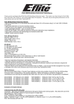
F-16 ARF Assembly Manual Specifications Wingspan: Length: Wing Area: Weight w/o Battery: Weight w/Battery: 28.0 in (710mm) 35.5 in (900mm) 195 sq in (12.6 sq dm) 18–20 oz (510–567 g) 23.5–30.5 oz (667–865 g) LOCKHEED MARTIN, F-16, associated emblems and logos, and body designs of vehicles are either registered trademarks or trademarks of Lockheed Martin Corporation in the USA and/or other jurisdictions, used under license by Horizon Hobby, Inc. Table of Contents Introduction......................................................................................................................... 2 Using the Manual................................................................................................................. 2 Product Registration............................................................................................................. 3 Contents of Kit/Parts Layout.................................................................................................. 3 Recommended Radio Equipment........................................................................................... 3 Recommended Sport Ducted Fan Setup.................................................................................. 3 Recommended High Power Ducted Fan Setup........................................................................ 4 Optional Accessories............................................................................................................ 4 Required Tools and Adhesives............................................................................................... 4 Notes Regarding Servos and ESC......................................................................................... 4 Note on Lithium Polymer Batteries......................................................................................... 4 Warning.............................................................................................................................. 4 Ducted Fan Installation......................................................................................................... 5 Wing and Stabilizer Installation............................................................................................ 7 Elevator and Aileron Servo Installation.................................................................................. 9 Landing Gear Installation Sport Ducted Fan Installation......................................................... 13 Landing Gear Installation High-Power Ducted Fan Installation............................................... 17 Speed Control and Receiver Installation Sport Ducted Fan Installation.................................... 21 Speed Control and Receiver Installation High-Powered Ducted Fan Installation....................... 22 Vertical and Ventral Fin Installation...................................................................................... 24 Motor Battery Installation Sport Ducted Fan Installation......................................................... 25 Motor Battery Installation High-Power Ducted Fan Installation............................................... 26 Missile Installation (Optional).............................................................................................. 26 Removing Fan and Motor for Servicing or Replacement........................................................ 27 Radio Programming........................................................................................................... 28 Control Throws.................................................................................................................. 28 Center of Gravity............................................................................................................... 29 Preflight............................................................................................................................. 29 Range Test Your Radio........................................................................................................ 30 Flying Your F-16................................................................................................................ 30 Safety Do’s and Don’ts for Pilots.......................................................................................... 30 Age Requirements.............................................................................................................. 30 Safety, Precautions and Warnings....................................................................................... 31 Warranty Information......................................................................................................... 31 Instructions for Disposal of WEEE by Users in the European Union........................................ 33 2008 Official Academy of Model Aeronautics Safety Code.................................................. 33 Building and Flying Notes:.................................................................................................. 35 2 Introduction The F-16 Fighting Falcon was originally designed in 1971 to be a multi-role fighter in both air-to-air combat and air-to-surface attacks. Today the F-16 is known for its amazing maneuverability, precision strike and attack capabilities and speed. The F-16’s versatility allows it to be equipped with a variety of weapons, including missiles or bombs. The Fighting Falcon is still in use today and is currently serving many countries. The USAF uses F-16s in their Thunderbird demonstrations. E-flite’s F-16 400 DF (ducted fan) is designed to replicate the full-scale F-16 as a performance sport scale model. Constructed of lightweight, durable injection molded foam, the F-16 is beautifully finished with a highly visible USAF Thunderbirds trim scheme. The F-16 400 DF also includes molded panel lines and custom applied decals for added scale appearance. It is highly prefabricated with molded servo pockets, prehinged flight surfaces and a magnetic battery hatch to get you in the air faster. The F-16 is capable of smooth, aerobatic maneuvers sure to please any crowd and the USAF Thunderbirds trim scheme will make all of your friends jealous. The E-flite F-16 400 DF will offer the ambitious sport scale modeler just the thrill he’s been looking for. Using the Manual This manual is divided into sections to help make assembly easier to understand, and to provide breaks between each major section. In addition, check boxes have been placed next to each step to keep track of its completion. Steps with a single circle () are performed once, while steps with two circles ( ) indicate that the step will require repeating, such as for a right or left wing panel, two servos, etc. Remember to take your time and follow the directions. E-flite F-16 ARF Assembly Manual Product Registration Register your product online at: www.e-fliterc.com/register/ Contents of Kit/Parts Layout Replacement Parts EFL7077 EFL7078 EFL7079 EFL7080 EFL7081 EFL7082 EFL7083 Canopy/Hatch Stabilizer Set Exhaust Nozzle and Nose Cone Missiles and Launch Rails Landing Gear Set w/Hardware Gear Doors and Ventral Fins Pushrod Kit Recommended Radio Equipment You will need a minimum 4-channel transmitter, receiver, and four or five servos (if using nose gear steering). You can choose to purchase a complete radio system. If you are using an existing transmitter, just purchase the other required equipment separately. We recommend the crystal-free, interference-free Spektrum™ DX6i 2.4GHz DSM® 6-channel system. If using your own transmitter, we recommend the E-flite S60 Super Sub-Micro servos . If you own the Spektrum DX6i radio, just add the AR6200 DSM2™ 6-channel receiver and four or five (nose gear steering) E-flite S60 Super Sub-Micro servos. Complete Radio System SPM6600 DX6i DSM2 6CH system Recommended Sport Ducted Fan Setup Fan and Motor:Delta-V 480 65mm EDF System (EFLDF480) ESC:40-Amp Lite Pro Switch-Mode BEC Brushless ESC (EFLA1040L) Transmitter:Spektrum 2.4 GHz DX6i 6-Channel Air System (SPM6600) Receiver:DSM2 AR6200 6-Channel (SPMAR6200) Battery:2100mAh 3-Cell/3S 11.1V 20C Pro Lite V2 LiPo,16AWG (THP21003SPL2) EFLREX3L 3-inch Extension, Lightweight (2) EFLREX9L 9-inch Extension, Lightweight (2) Or Purchase Separately SPMAR6200AR6200 DSM2 6-Channel FullRange Receiver (for DX6i or DX7) And EFLRS60S60 Super Sub-Micro Servo (4, 5 if using nose gear steering) Note: If you are not using a computer radio, you will be required to purchase the following items: EFLRYH3 3-inch Y-Harness, Lightweight EXRA320Y-Harness 6-inch/Reverser Standard The Spektrum trademark is used with permission of Bachmann Industries, Inc. E-flite F-16 ARF Assembly Manual 3 Recommended High Power Ducted Fan Setup The high power setup listed requires a slightly modified radio and battery installation to achieve the correct CG location. All of the modifications and parts needed are covered in the manual. Note: The high power setup adds many benefits like: • Incredible vertical performance • Improved speed over the early OEM power system. This performance does come at a price: • Requires a high quality battery • Requires a 60-amp ESC • Reduced flight time • Requires throttle management due to the higher loads on the ESC, battery, and minimal cooling Fan and Motor:Delta-V 480 65mm EDF System 4800KV (EFLDF480B) ESC:60-Amp Pro Switch-Mode BEC Brushless ESC (EFLA1060) Transmitter:Spektrum 2.4 GHz DX6i 6-Channel Air System (SPM6600) Receiver:DSM2 AR6200 6-Channel (SPMAR6200) Battery:2600mAh 3 Cell/3S 11.1V 20C Pro Lite V2 LiPo,13AWG (THP26003SPL2) EFLREX3L 3-inch Extension, Lightweight EFLREX6L 6-inch Extension, Lightweight (2) EFLREX12L12-inch Extension, Lightweight (2) 4 Optional Accessories EFLA110 Power Meter EFLC3005Celectra™ 1- to 3-Cell Li-Po Charger EFLC505Intelligent 1- to 5-Cell Balancing Charger Required Tools and Adhesives Tools & Equipment Dental floss/string Epoxy brushes Felt tip marker Hobby knife (#11 blade) Low-tack tape Mixing cups Mixing sticks Paper towels Pin drill Rubber bands Rubbing alcohol Sandpaper Side cutter Small hand file Phillips screwdriver: #00, #1 Drill bit: 1/16-inch (1.5mm), 5/64-inch (2mm), 1/8-inch (3mm) Adhesives Threadlock 6-Minute Epoxy (HAN8000) Medium CA (optional for missile installation) Notes Regarding Servos and ESC WARNING: Use of servos other than those we suggest may overload the BEC of the recommended Electronic Speed Control (ESC). Please use only the servos listed when utilizing the recommended ESC’s BEC, or the use of a separate BEC (like the UBEC) or receiver battery pack when using other servos. Note on Lithium Polymer Batteries Lithium Polymer batteries are significantly more volatile than alkaline or Ni-Cd/ Ni-MH batteries used in RC applications. All manufacturer’s instructions and warnings must be followed closely. Mishandling of LiPo batteries can result in fire. Always follow the manufacturer’s instructions when disposing of Lithium Polymer batteries. Warning An RC aircraft is not a toy! If misused, it can cause serious bodily harm and damage to property. Fly only in open areas, preferably at AMA (Academy of Model Aeronautics) approved flying sites, following all instructions included with your radio. Keep loose items that can get sucked into the intake, including loose clothing, or other objects such as pencils and screwdrivers. Especially keep your hands away from the intake during operation. During the course of building your F-16 we suggest that you use a soft base for the building surface. Such things as a foam stand, large piece of bedding foam or a thick bath towel will work well and help protect the model from damage during assembly. E-flite F-16 ARF Assembly Manual Ducted Fan Installation Required Parts Fuselage Motor wire (3) Ducted fan assembly Motor hatch Required Tools and Adhesives 6-minute epoxy Mixing cup Mixing stick Epoxy brush Low-tack tape Hobby knife with #11 blade At this time you will need to have chosen either the Sport or High-Powered Ducted Fan Setup. The installation of either Ducted Fan Assembly is identical, but later sections of the manual will be dedicated to either one setup or the other. m 1. Locate the fuselage assembly and motor hatch. E-flite F-16 ARF Assembly Manual m 2. Test fit the fan into the fuselage as shown. The wires from the motor will fit into the channel inside the fuselage. Press the fan into the fuselage so the tabs on the fan assembly leave an indentation in the foam inside the fuselage. If you find that the fan unit will not fit flush after you have made the indentions for the 3 tabs on the top of the fan unit then use a hobby knife to enlarge the indentions slightly. Make sure that the fan unit fits properly inside the molded channel in the fuselage. m 3. Remove the fan and connect the three motor wires supplied with the model to the wires from the motor. The colors may not match from the wires supplied to the motor. m 4. Insert the wires into the opening at the front of the notch inside the fuselage. This will allow them to exit into the battery/radio compartment of the fuselage. 5 m 5. Remove the decal from the fan assembly. This will allow the epoxy to be applied directly to the housing in the next step. m 7. Insert the fan assembly into the fuselage, making sure to guide the wires into the notch in the fuselage. If not, the fan hatch will not fit correctly when it is time to install. Use low-tack tape to keep the fan held in position until the epoxy fully cures. Make sure the tape does not come in contact with the fuselage decals. If it does, the tape could remove the decal from your model. Make sure to pay attention to ALL the decals near the fan hatch on both the top and bottom of the fuselage. m m 9. Once the hatch has been fit, use a small amount of 6-minute epoxy to glue the hatch in position. The hatch only required a few dots of epoxy to keep in position. Using too much epoxy will make it difficult to remove the hatch if the fan assembly or motor require maintenance. 6. Mix a small amount of epoxy and apply a few dots of it to the fan housing where it will contact the fuselage. Do not use an excess of epoxy in case the fan requires removal for maintenance. m 6 Use a black or dark blue marker on the edges of the hatch and fuselage where the decal is placed to hide their edges when the hatch is installed. Test your marker where it can’t be seen to make sure it won’t attack the foam. 8. Remove the tape from the fuselage. Test fit the fan hatch over the fan. Press the hatch tightly against the fan housing so the tabs on the housing leave indentations on the inside of the hatch. If the hatch does not fit the fuselage flush after the indentions have been made use a hobby knife to enlarge the indentions. E-flite F-16 ARF Assembly Manual Wing and Stabilizer Installation Required Parts Fuselage Wing panel (right and left) Stabilizer (right and left) 2mm x 12mm self-tapping screw (4) Required Tools and Adhesives 6-minute epoxy Mixing cup Mixing stick Epoxy brush Paper towel Rubbing alcohol Sandpaper Phillips screwdriver: #1 Small hand file Tape should not be used to hold the hatch in position while the epoxy cures during this step as it will remove the decal. Use either weights or rubber bands to keep the hatch in position until the epoxy cures. Note: During the manufacturing process it is possible that a slight amount of glue may seep into the inner side of the wing joiner socket. If you are having trouble with the wing fitting flush against the fuselage, check the inside of the joiner socket. If some glue has seeped into the socket, use a small hand file to remove it. m 1. Test fit the wing panel to the fuselage by sliding the joiners into the joiner sockets of the fuselage. The panel must fit tightly against fuselage when installed. If it does not, you may be required to sand the end of the joiner slightly so the wing will have a flush fit against the fuselage. E-flite F-16 ARF Assembly Manual Important: You will be required to quickly perform the next few steps before the epoxy begins to cure. Read through the following steps to prepare yourself for the gluing process. m 2. After checking the fit, remove the wing panel from the fuselage. Prepare 1/4-ounce (10cc) of 6-minute epoxy and brush a very light coating of epoxy on the wing and fuselage where they contact each other. Also brush some glue into the inside of the joiner socket. 7 m 4. Fit the remaining wing panel to the fuselage. Stand 6–9 feet (2–3 meters) from the front of the airframe. When viewed from the front, both panels should be flat (parallel) along the bottom to be properly aligned. Use sandpaper to lightly sand the plastic joiner to correct the alignment. Note: You can use a paper towel that has had rubbing alcohol applied to it to remove any excess epoxy from your airframe. Use care not to get the alcohol on the decals as it could damage them. m 3. Slide the wing panel back into position on the fuselage, pressing the wing tightly against the fuselage. It is best to hold the wing panel in position until the epoxy cures, as tape will damage the decal if it is applied directly to the decal. Be sure to check the alignment of the wing while the glue is drying. Use the picture in the next step for reference. 8 m 7. Check the fit of the stabilizer to the fuselage. Note that the control horn on the stabilizer will face toward the bottom of the fuselage when the stabilizer is installed. m 5. After fitting and aligning the second wing panel, repeat Steps 2 and 3 to glue the wing panel to the fuselage. m 6. Before installing the stabilizer, you will need to break in the elevator hinges. This is done by flexing the elevator up and down a few times. Don’t move the elevator too far and damage the hinge. Start with small movements and work up to an amount that will be slightly greater than the suggested high rate elevator control throw found on Page 31. E-flite F-16 ARF Assembly Manual m 8. Use two 2mm x 12mm self-tapping screws and a #1 Phillips screwdriver to secure the stabilizer to the fuselage. Use care not to over-tighten the screws and cause damage to the fuselage or stabilizer. Elevator and Aileron Servo Installation Required Parts Servo (4) Assembled airframe Radio system Fuselage decal (right and left) Standard single-sided servo arm (4) 1. Use a hobby knife to trim the decal on the bottom of the wing to expose the pocket for the aileron servo. Prepare both the right and left wing at this time. 2 7/8-inch (73mm) pushrod wire w/clevis (2) 5 7/8-inch (150mm) pushrod wire w/clevis (2) There are to different sets of servo extensions listed for the F-16. The high power setup requires a different length of extensions so that the receiver can be placed farther forward and the battery in the aft compartment to achieve the correct CG. 9. Repeat Steps 6 through 8 to attach the remaining stabilizer to the fuselage. Required for Sport Ducted Fan: 3-inch (76mm) servo extension (2) 9-inch (228mm) servo extension (2) Required for High-Power Ducted Fan: 6-inch (152mm) servo extension (2) 12-inch (305mm) servo extension (2) Required Tools and Adhesives 6-minute epoxy Mixing cup Mixing stick Epoxy brush Paper towel Rubbing alcohol Sandpaper Pin drill Dental Floss/String Felt-tipped pen Drill bit: 1/16-inch (1.5mm) Phillips screwdriver: #00 Hobby knife w/#11 blade You can use compressed air to blow away the remains of the decal. Note: Before preparing the aileron and elevator servos for installation, it is suggested to read through the Radio Programming section of this manual beginning on Page 18. This section will guide you through setting up the necessary mixing required to operate the servos installed in your F-16. This mixing reduces the amount of complexity and extensions required, keeping the weight at its lowest for the best performance for your model. Note: The stabilizer tips will be lower than the center of the stabilizer at the fuselage when the fuselage is upright. This is scale for the F-16 and is correct. E-flite F-16 ARF Assembly Manual 9 2. Use your radio system to center the servos that will be used for the ailerons. Remove the stock servo horns from the servos using a #00 Phillips screwdriver and install the standard single-sided servo arm on the servos as shown. Make sure to prepare a right and left servo as shown. m 4. Remove the servo and scuff the surface of the servo where it contacts the wing using sandpaper. Clear any residue left from the sanding process using a paper towel and rubbing alcohol. Mix a small amount of 6-minute epoxy. Place a small amount of epoxy in the servo pocket, then install the servo, pressing it into the epoxy. This will keep the servo secure in the wing during the operation of your model. m 3. Test fit the aileron servo into the pocket in the bottom of the wing. Note that the servo output will face to the front of the aircraft. 5. Repeat Steps 3 and 4 to install the aileron servo in the opposite wing panel. Be very careful to use only a small amount of epoxy when attaching the servos. Using an excessive amount of glue could cause some of the excess to seep inside of the servo case and could bind the servo, resulting in servo failure. 10 6. Use your radio system to center the servos that will be used for the elevators. Remove the stock servo horns from the servos using a #00 Phillips screwdriver and install the standard single-sided servo arm on the servos as shown. Make sure to prepare a right and left servo as shown. 7. Test fit the elevator servo into the pocket on the side of the fuselage. Note that the servo output will face to the front of the aircraft. Remove the servo and scuff the surface of the servo that contacts the fuselage using sandpaper. Clear any residue left from the sanding process using a paper towel and rubbing alcohol. Mix a small amount of 6-minute epoxy. Place a small amount of epoxy in the servo pocket, then install the servo, pressing it into the epoxy. This will keep the servo secure in the fuselage during the operation of your model. E-flite F-16 ARF Assembly Manual 8. Connect a 9-inch (228mm) (Sport Ducted Fan) or 12-inch (305mm) (High-Power Ducted Fan) servo extension to the lead on the elevator servo. Tie a piece of string or dental floss around the connection to prevent the two from unplugging accidentally. Install an extension for both elevator servos at this time. 9. Connect a 3-inch (76mm) (Sport Ducted Fan) or 6-inch (152mm) (High-Power Ducted Fan) servo extension to the lead on the aileron servo. Tie a piece of string or dental floss around the connection to prevent the two from unplugging accidentally. Install an extension for both aileron servos at this time. E-flite F-16 ARF Assembly Manual 10. Carefully lay the extension from the elevator servos into the channel on each side of the fuselage. The aileron extension will than be placed on top of the elevator extension. Both extensions are then inserted into the fuselage where the channel turns to enter the fuselage. Before inserting the extension leads through the fuselage, mark each lead according to which servo it is connected to. (Right Elevator, Left Elevator-this will help with set up later). You can use a small felt-tipped marker or a piece of tape for this. 11. Locate the decal to cover the channel for the aileron and elevator extensions. A right and left decal has been supplied to cover the channels. Make sure to use the correct decal on each side of your aircraft. 12. Remove the backing from the decal. Starting at the front, hold the rear of the decal up and align the trim scheme from the decal to the scheme on the aircraft. Carefully work toward the rear of the fuselage, pressing the decal down and guiding the extensions under the decal to remain in the channel. 11 A water-based dark blue paint can be used to paint the exposed white foam that is shown on the wing where the servo lead runs through. mmm 1 4. Attach the clevis on the pushrod to the outer hole of the elevator control horn. Snap the clevis together so it is secure on the control horn. 16. Repeat Steps 13 and 14 to install the 2 7/8-inch (73mm) pushrod wire with clevis for the ailerons. The end at the servo will attach to the outermost hole in the aileron servo arm, and the clevis will attach to the outer hole on the control horn as shown. Make sure to install both the left and right aileron linkages at this time. mmm 1 3. Insert the end of the 5 7/8-inch (150mm) pushrod wire with the clevis and “Z” bend into the hole of the servo arm that is in one hole from the end of the horn as shown. The pushrod will enter from the top of the horn. Insert the wire so it appears as shown in the second image. 15. Repeat Steps 13 and 14 to install the second elevator linkage. The left and right linkages will be mirror images of each other when installed. You may have to slightly enlarge the hole in the servo horns for the pushrod wire. Use a pin drill and 1/16-inch (1.5mm) drill bit to do so. 12 E-flite F-16 ARF Assembly Manual Landing Gear Installation Sport Ducted Fan Installation Required Parts 2mm nut Servo Radio system Assembled fuselage Long 3D servo horn Nose gear wire w/wheel Gear door (right and left Main landing gear w/wheels 2mm x 10mm machine screw Brass steering arm bushing 1/16-inch wheel collar w/screw Nose gear steering arm w/screw 2mm x 8mm self-tapping screw (4) Required Tools and Adhesives Side cutter Pin drill 6-minute epoxy Mixing cup Mixing stick Epoxy brush Paper towel Rubbing alcohol Threadlock Sandpaper Hobby knife w/#11 blade Drill bit: 5/64-inch (2mm) Phillips screwdriver: #00, #1 m 1. Use a #1 Phillips screwdriver and two 2mm x 8mm self-tapping screws to attach the landing gear door to the fuselage. The two holes for the screws have small holes so they can be located on the bottom of the fuselage. Note the direction of the gear door as shown with the narrow end of the door facing the front of the aircraft. 3. Use a hobby knife with a #11 blade to remove the decal from the bottom of the fuselage to expose the slot for the main landing gear. 4. Insert the main landing gear into the slot in the bottom of the fuselage. You will need to flex the gear inward slightly to get it to fit into the slot. 2. Repeat Step 1 to install the remaining gear door on the bottom of the fuselage. Note: The landing gear assembly is optional. The F-16 can be flown with or without the landing gear. E-flite F-16 ARF Assembly Manual 13 5. Lift the canopy hatch from the top of the fuselage. The hatch is held in position using four small magnets and will take a light amount of force to remove. Note: Before installing the steering servo arm, it is suggested to read through the Radio Programming section of this manual found on Page 30. 6. Locate a long 3D servo arm and use side cutters to remove one of the arms from the horn as shown. 14 7. Use a pin drill and 5/64-inch (2mm) drill bit to enlarge the outer hole on the servo arm. 8. Slide the 2mm x 10mm machine screw through the brass steering arm bushing. 9. Slide the brass steering arm bushing through the slot in the steering arm. Note the direction of the screw in relationship to the steering arm. 10. Use a #1 Phillips screwdriver to start the screw in to the outermost hole in the servo arm. Tighten the screw so the brass steering arm bushing is tight against the servo arm. E-flite F-16 ARF Assembly Manual 11. Thread a 2mm nut onto the screw from underneath the servo arm. Tighten the screw and nut to secure the bushing and steering arm. Always use threadlock on metal-to-metal fasteners to prevent them from vibrating loose. 12. Remove the original servo arm from the servo using a #00 Phillips screwdriver. After centering the steering servo, install the long 3D arm prepared in the previous steps on the servo as shown. E-flite F-16 ARF Assembly Manual 13. Test fit the steering servo into the pocket inside the fuselage. Note that the servo output faces to the rear of the aircraft. Remove the servo and scuff the surface of the servo that contacts the fuselage using sandpaper. Clear any residue left from the sanding process using a paper towel and rubbing alcohol. Mix a small amount of 6-minute epoxy. Place a small amount of epoxy in the servo pocket, then install the servo, pressing it into the epoxy. This will keep the servo secure in the fuselage during the operation of your model. 15. There are also two small flat areas on the nose gear that will face to the front of the aircraft. Please remember these flat areas for later in the nose gear installation. 16. Use a hobby knife and #11 blade to remove the decal from the bottom of the fuselage to expose the slot for the nose gear wire. 14. Locate the nose gear. Notice there is a slight bend to the gear wire. This bend will angle the gear forward in a scale-like manner when it has been installed. 15 17. Slide the nose gear into the slot from the bottom of the fuselage. You will need to slide the gear wire through the 1/16-inch wheel collar before it continues its journey into the fuselage as shown in the following photos. 18. The nose gear will slide into the hole in the steering arm as its final destination. The screw at the steering arm will then be tightened so it is resting in the flat area as indicated back in Step 14. Use a #1 Phillips screwdriver to tighten the screw in the steering arm. Always remember to use threadlock on metal-to-metal fasteners to prevent them from vibrating loose. 19. Position the gear so there is a slight gap between the steering arm and the servo horn so they do not bind during the operation of the nose gear. With the wheel collar resting lightly against the fuselage as shown, use a #1 Phillips screwdriver to tighten the screw in the wheel collar. The screw at the wheel collar will be tightened so it is resting in the flat area as indicated back in Step 14. Always remember to use threadlock on metalto-metal fasteners to prevent them from vibrating loose. Note: The steering arm and wheel will be parallel to each other as illustrated below. You can place a piece of paper between the steering arm and servo arm to achieve the correct amount of gap before securing the wheel collar. 16 E-flite F-16 ARF Assembly Manual Landing Gear Installation High-Power Ducted Fan Installation Required Parts 2mm nut Servo Steering servo mounting block Assembled fuselage Long 3D servo horn Nose gear wire w/wheel Gear door (right and left Main landing gear w/wheels 2mm x 10mm machine screw Brass steering arm bushing 1/16-inch wheel collar w/screw Nose gear steering arm w/screw 2mm x 8mm self-tapping screw (4) Required Tools and Adhesives Side cutter Pin drill 6-minute epoxy Mixing cup Mixing stick Epoxy brush Paper towel Rubbing alcohol Threadlock Sandpaper File Hobby knife w/#11 blade Drill bit: 5/64-inch (2mm) Phillips screwdriver: #00, #1 m 1. Use a #1 Phillips screwdriver and two 2mm x 8mm self-tapping screws to attach the landing gear door to the fuselage. The two holes for the screws have small holes so they can be located on the bottom of the fuselage. Note the direction of the gear door as shown with the narrow end of the door facing the front of the aircraft. 3. Use a hobby knife with a #11 blade to remove the decal from the bottom of the fuselage to expose the slot for the main landing gear. 4. Insert the main landing gear into the slot in the bottom of the fuselage. You will need to flex the gear inward slightly to get it to fit into the slot. 2. Repeat Step 1 to install the remaining gear door on the bottom of the fuselage. Note: The landing gear assembly is optional. The F-16 can be flown with or without the landing gear. E-flite F-16 ARF Assembly Manual 17 5. Lift the canopy hatch from the top of the fuselage. The hatch is held in position using four small magnets and will take a light amount of force to remove. 6. Locate a long 3D servo arm and use side cutters to remove one of the arms from the horn as shown. 7. Use a pin drill and 5/64-inch (2mm) drill bit to enlarge the outer hole on the servo arm. 6. Use 6-minute epoxy to glue the steering servo mounting block in the fuselage. Note that the notch in the block faces to the front of the fuselage. 9. Slide the brass steering arm bushing through the slot in the steering arm. Note the direction of the screw in relationship to the steering arm. 10. Use a #1 Phillips screwdriver to start the screw into the outermost hole in the servo arm. Tighten the screw so the brass steering arm bushing is tight against the servo arm. Note: Before installing the steering servo arm, it is suggested to read through the Radio Programming section of this manual found on Page 30. 18 8. Slide the 2mm x 10mm machine screw through the brass steering arm bushing. E-flite F-16 ARF Assembly Manual 11. Thread a 2mm nut onto the screw from underneath the servo arm. Tighten the screw and nut to secure the bushing and steering arm. Always use threadlock on metal-to-metal fasteners to prevent them from vibrating loose. 13. Test fit the steering servo into the steering servo mounting block inside the fuselage. Note that the servo output faces to the rear of the aircraft. Remove the servo and scuff the surface of the servo that contacts the fuselage using sandpaper. Clear any residue left from the sanding process using a paper towel and rubbing alcohol. Mix a small amount of 6-minute epoxy. Place a small amount of epoxy in the servo pocket, then install the servo, pressing it into the epoxy. This will keep the servo secure in the fuselage during the operation of your model. 15. There are also two small flat areas on the nose gear that will face to the front of the aircraft. 16. Use a file to make a flat on the opposite side of the one near the top of the nose gear wire as shown. 12. Remove the original servo arm from the servo using a #00 Phillips screwdriver. After centering the steering servo, install the long 3D arm prepared in the previous steps on the servo as shown. E-flite F-16 ARF Assembly Manual 14. Locate the nose gear. Notice there is a slight bend to the gear wire. This bend will angle the gear forward in a scale-like manner when it has been installed. 19 17. Use a hobby knife and #11 blade to remove the decal from the bottom of the fuselage to expose the slot for the nose gear wire. 18. Slide the nose gear into the slot from the bottom of the fuselage. You will need to slide the gear wire through the 1/16-inch wheel collar before it continues its journey into the fuselage as shown in the following photos. 19. The nose gear will slide into the hole in the steering arm as its final destination. The screw at the steering arm will then be tightened so it is resting in the flat area made in Step 16. Use a #1 Phillips screwdriver to tighten the screw in the steering arm. Always remember to use threadlock on metal-to-metal fasteners to prevent them from vibrating loose. 20. Position the gear so there is a slight gap between the steering arm and the servo horn so they do not bind during the operation of the nose gear. With the wheel collar resting lightly against the fuselage as shown, use a #1 Phillips screwdriver to tighten the screw in the wheel collar. The screw at the wheel collar will be tightened so it is resting in the flat area as indicated back in Step 14. Always remember to use threadlock on metalto-metal fasteners to prevent them from vibrating loose. Note: The steering arm and wheel will be parallel to each other as shown in the following illustration. You can place a piece of paper between the steering arm and servo arm to achieve the correct amount of gap before securing the wheel collar. 20 E-flite F-16 ARF Assembly Manual Speed Control and Receiver Installation Sport Ducted Fan Installation 2. Apply a small piece of hook and loop tape to the bottom of the speed control. Required Parts Speed control Receiver Assembled airframe Hook and loop tape ESC Location Note: Due to the current draw of the system and the location of the electronics, we recommend that throttle management is used during each flight. Using full power throughout the duration of the flight will result in shorter flight times and could result in a shorter life span for the electronics and batteries. Note: Work through Step 3 before removing the backing from the hook and loop tape. Installation of the speed control can be tricky, and the stickiness of the hook and loop tape will make the installation even trickier. Keeping the backing on until ready will allow you to practice the installation of the speed control before your final performance. 1. Plug the wires from the speed control and motor together. The wires from the motor will be just long enough that they can be accessed from the cockpit area of your model. E-flite F-16 ARF Assembly Manual 3. Install the speed control back in the fuselage as indicated on the photos. You will need to guide the motor wires into the fuselage while installing the speed control. Note: Before plugging in the servos, it is suggested to read through the Radio Programming section of this manual beginning on Page 27. This section will guide you through setting up the necessary mixing required to operate the servos installed in your F-16. This mixing reduces the amount of complexity and extensions required, keeping the weight at its lowest for the best performance from your model. Be sure to refer to your motor and ESC manuals as to the correct setup of the power system. You may need to change the PWM switching frequency and or the timing according to your setup. 21 Speed Control and Receiver Installation High-Powered Ducted Fan Installation 4. Plug the extensions from the ailerons and elevators into the proper ports of the receiver. Also plug the lead from the steering servo and speed control into their proper ports on the receiver as well. Required Parts Speed control Assembled airframe Receiver Hook and loop tape 3-inch (76mm) servo extension Receiver Location Required Tools Pin drill 22 5. Use a small piece of hook and loop tape to mount the receiver in the fuselage as shown. The edge of the receiver should be flush with the edge of the cockpit opening as seen in the following step. 6. Use a small piece of hook and loop tape to mount the remote receiver alongside of the steering servo. Make sure the position of the remote receiver will not interfere with the operation of the steering servo when it is installed. Drill bit: 1/8-inch (3mm) Note: Due to the current draw of the system and the location of the electronics, we recommend that throttle management is used during each flight. Using full power throughout the duration of the flight will result in shorter flight times and could result in a shorter life span for the electronics and batteries. 1. Plug the wires from the speed control and motor together. The wires from the motor will be just long enough that they can be accessed from the cockpit area of your model. E-flite F-16 ARF Assembly Manual 2. Apply a small piece of hook and loop tape to the bottom of the speed control. Note: Before plugging in the servos, it is suggested to read through the Radio Programming section of this manual beginning on Page 27. This section will guide you through setting up the necessary mixing required to operate the servos installed in your F-16. This mixing reduces the amount of complexity and extensions required, keeping the weight at its lowest for the best performance from your model. 3. Install the speed control back in the fuselage as indicated on the photos. You will need to guide the motor wires into the fuselage while installing the speed control. The speed control must be positioned at least 21/8-inches (54mm) behind the edge of the canopy opening or the motor battery will not fit into the fuselage. Note: Work through Step 3 before removing the backing from the hook and loop tape. Installation of the speed control can be tricky, and the stickiness of the hook and loop tape will make the installation even trickier. Keeping the backing on until ready will allow you to practice the installation of the speed control before your final performance. 4. Use a 3-inch (76mm) servo extension on the speed control to connect it to the receiver. Plug the extensions from the ailerons and elevators into the proper ports of the receiver. Also plug the lead from the steering servo into the rudder port on the receiver as well. 21/8-inches (54mm) ESC Location Be sure to refer to your motor and ESC manuals as to the correct setup of the power system. You may need to change the PWM switching frequency and or the timing according to your setup. E-flite F-16 ARF Assembly Manual 23 5. Use a small piece of hook and loop tape to mount the receiver in the front of the fuselage as shown. The receiver should be as close to the nose gear steering block as possible. Use a hobby knife to cut a small notch for the antenna to rest in. Vertical and Ventral Fin Installation Required Parts Vertical fin Assembled airframe Ventral fin (right and left) Required Tools and Adhesives 6-minute epoxy Mixing cup Mixing stick Epoxy brush Paper towel Rubbing alcohol Sandpaper Hobby knife w/#11 blade m 2. Test fit the ventral fin in the slot on the bottom of the fuselage. The taller portion of the fin will face to the front of the fuselage and the decal will face to the wing tip. Once satisfied with the fit remove the fin from the fuselage. Mix a small amount of 6-minute epoxy. Apply the epoxy in the slot and insert the ventral fin in the slot. Allow the epoxy to fully cure before proceeding to the fin installation. m 1. Use a hobby knife w/#11 blade to trim the decal from the opening on the bottom of the fuselage for the ventral fin. Prepare the slots for both the left and right ventral fins at this time. 24 6. Use a small piece of hook and loop tape to mount the remote receiver in the front of the fuselage as shown. You will need to use a pin drill and 1/8-inch (3mm) drill bit to drill a hole for the antenna as shown. 3. Repeat Steps 1 and 2 to install the remaining ventral fin on the bottom of the fuselage. E-flite F-16 ARF Assembly Manual 4. Insert the vertical fin into the pocket on the top of Motor Battery Installation the fuselage. Stand 6–8 feet (3–4 meters) from the Sport Ducted Fan Installation rear of the airframe. Check that the angle between the wing panels and fin are equal. The position of Required Parts the fin can be moved to correct for any alignment Motor battery Assembled airframe issues. Once satisfied with the fit, remove the fin Hook and loop tape from the fuselage. Prepare 1/4-ounce (10cc) of 6-minute epoxy and brush a light coating on the fin and in the pocket on the fuselage where they 1. Apply the hook and loop tape to the bottom of contact each other. Insert the fin back into the the battery. Use the softer fabric side of the hook pocket and check the alignment again. As the and loop tape on the battery. epoxy cures, continue to check the alignment of the fin to the wing until the epoxy has fully cured. E-flite F-16 ARF Assembly Manual 3. Place the battery into the battery compartment in the fuselage. The battery will be positioned as far back in the compartment as possible to achieve the correct Center of Gravity when you are using the recommended setup. 2. Apply the hook and loop tape inside the fuselage in the battery compartment. Use the harder plastic side of the hook and loop tape on the battery. 25 Motor Battery Installation High-Power Ducted Fan Installation Required Parts Motor battery Assembled airframe Hook and loop tape 1. Apply the hook and loop tape to the bottom of the battery. Use the softer fabric side of the hook and loop tape on the battery. 3. Place the battery into the battery compartment in the fuselage. The battery will be positioned in the compartment to achieve the correct Center of Gravity when you are using the recommended setup. The forward end of the battery should just clear the nose wheel steering arm. Missile Installation (Optional) Required Parts Missile (2) Assembled airframe Required Tools and Adhesives Medium CA Note: The installation of the missiles on your model is not scale for this paint scheme and is considered optional. The missiles will be attached permanently and will not affect the flight performance. m 1. Locate the missile included with your model. Inspect each missile to locate the flat areas between the fins of the missile. These flat areas are the gluing surfaces used for their installation. 26 2. Apply the hook and loop tape inside the fuselage in the battery compartment. Use the harder plastic side of the hook and loop tape on the battery. E-flite F-16 ARF Assembly Manual Removing Fan and Motor for Servicing or Replacement m 2. The missile rails on the wing have flat spots that will correspond to the flat areas on the missile. Required Tools and Adhesives 6-minute epoxy Mixing cup Mixing stick Epoxy brush Paper towel Rubbing alcohol Sandpaper Hobby knife w/#11 blade 2. Once you are sure that you have cut through the hatch joints, use a small amount of force to rock the hatch in a rolling motion side to side. A small amount of movement should break any missed glue joints. Remove the hatch/fan assembly. Please note that the hatch is glued in with small amounts of glue as instructed earlier in this manual. If you have removed your hatch we suggest that you glue it back in at the same glue locations with a small amount of 6-minute epoxy. We also suggest that you use a fresh sharp #11 blade to make all cuts. This will help make the process easier and the cut line will be smaller, cleaner and much less noticeable. m 3. Use medium CA to glue the missile to the mount at the wing tip. Allow the CA to fully cure before installing the remaining missile. 1. Use a hobby knife with a #11 blade, or a razor saw with a fine tooth blade, to cut through the glue joints on the hatch. When gluing the hatch back in position make sure that the motor wires are routed in the slot on the top of the fuselage. If they are not in this slot the hatch will not seat properly. Follow the procedure at the beginning of the manual to replace the fan assembly and hatch. 4. Repeat Steps 1 through 3 to install the remaining missile to the mount on the opposite wing tip. E-flite F-16 ARF Assembly Manual 27 Radio Programming The programming listed is showing the base radio set up for the Spektrum DX6i radio. This programming will allow you to use the gear channel (channel #5) for the second elevator servo. This will eliminate the need for any servo reversers or Y-harnesses. It will also show you how to use a P-MIX to turn off the gear channel switch when using this channel for a control surface. If you choose not to use a computer radio for your F-16, you will be required to use a Y-harness for the ailerons (EFLRYH3) and a servo reversing Y-harness (EXRA320) for the elevators. Travel Adjust, Sub Trim and Dual Rates are not listed and should be adjusted according to each individual model and preference. Note: The programming listed is using the electronics that we have recommended. Using other types of equipment may require changes to the set up. Channel List Throttle Right Aileron Right Elevator Rudder Left Elevator Left Aileron 28 Servo Receiver Port THRO AILE ELEV RUDD GEAR AUX 1 Reversing Throttle Right Aileron Right Elevator Rudder Gear/Left Elevator Aux1/Left Aileron N N R R R N Wing and Tail Mix DUALAILEACT (This will activate the left aileron) V-tail INH ELEVON INH MIX 1 (This mix will deactivate the gear channel switch) GEAR GEAR ACT Rate D -100%, U -100% SW ON TRIM INH MIX 2 (This mix will activate the left elevator half) ELEV GEAR ACT Rate D +100%, U +100% SW ON TRIM ACT Control Throws 1. Turn on the transmitter and receiver of your F-16. Check the movement of the rudder using the transmitter. When the stick is moved right, the rudder should also move right. Reverse the direction of the servo at the transmitter if necessary. 2. Check the movement of the elevator with the radio system. Moving the elevator stick down will make the airplane elevator move up. 3. Check the movement of the ailerons with the radio system. Moving the aileron stick right will make the right aileron move up and the left aileron move down. 4. Use a ruler to adjust the throw of the elevator, ailerons and rudder. Adjust the position of the pushrod at the control horn to achieve the following measurements when moving the sticks to their endpoints. The sport power setup usually results in a forward CG location. The use of high rate elevator throw is recommended for this setup. E-flite F-16 ARF Assembly Manual Aileron High Rate Up 1-inch Down 7/8-inch (25mm) (22mm) Aileron Low Rate Up 3/4-inch Down 5/8-inch (19mm) (16mm) Elevator High Rate Up 3/8-inch Down 3/8-inch (10mm) (10mm) Elevator Low Rate Up 1/4-inch Down 1/4-inch (7mm) (7mm) Note: Measurements are taken at the inner or widest point on the control surface. Nose Wheel Steering (High Rate or Taxi) Left 7/16-inch (12mm) Right 7/16-inch (12mm) Nose Wheel Steering (Low Rate or Takeoff) Left 1/4-inch (7mm) Right 1/4-inch (7mm) Center of Gravity An important part of preparing the aircraft for flight is properly balancing the model. Caution: Do not inadvertently skip this step! The recommended Center of Gravity (CG) location for the F-16 is 2 3/16–2 9/16-inch (55–65mm) back from the leading edge of the wing. Mark the location for the Center of Gravity on the bottom of the wing next to the fuselage as shown. When balancing your F-16, support the plane rightside-up at the marks made on the bottom of the wing with your fingers or a commercially available balancing stand. Adjust components as necessary so the model hangs level or slightly nose down. This is the correct balance point for your model. You might find with the different power and landing gear configurations that you need to shift the battery slightly in the compartment or add a small amount of weight to either the front or back of the fuselage to achieve the correct balance. Note: Steering measurement is taken at the end of the Aluminum Steering Arm over the steering servo arm. Preflight Check Your Radio Before going to the field, be sure that your batteries are fully charged per the instructions included with your radio. Charge both the transmitter and receiver pack for your airplane. Use the recommended charger supplied with your particular radio system, following the instructions provided with the radio. In most cases, the radio should be charged the night before going out flying. Note: Keep loose items that can get drawn into the intake away from the intake. These items include loose clothing, or other objects such as pencils and screwdrivers. Double-check that all controls (aileron, elevator, rudder and throttle) move in the correct direction. Check the radio installation and make sure all the control surfaces are moving correctly (i.e. the correct direction and with the recommended throws). Test run the motor and make sure it transitions smoothly from off to full throttle and back. Also ensure the engine is installed according to the manufacturer’s instructions, and it will operate consistently. Check all the control horns, servo horns, and clevises to make sure they are secure and in good condition. Replace any items that would be considered questionable. Failure of any of these components in flight would mean the loss of your aircraft. These are general guidelines measured from our own flight tests. You can experiment with higher rates to match your preferred style of flying. After the first flights, the CG position can be adjusted for your personal preference. E-flite F-16 ARF Assembly Manual 29 Range Test Your Radio 1. Before each flying session, be sure to range check your radio. This is accomplished by turning on your transmitter with the antenna collapsed. Turn on the receiver in your airplane. With your airplane on the ground and the engine running, you should be able to walk 30 paces (approximately 100 feet) away from your airplane and still have complete control of all functions. If not, don’t attempt to fly! Have your radio equipment checked out by the manufacturer. 2. Double-check that all controls (aileron, elevator, rudder and throttle) move in the correct direction. 3. Be sure that your transmitter batteries are fully charged, per the instructions included with your radio. Flying Your F-16 Flying the F-16 is a thrill and a treat all in one. Enjoy flying airshow maneuvers as you pretend to be the lead solo pilot for the USAF Thunderbirds airshow team. You will find that the lightweight, agile F-16 is very capable in the air yet docile for slow speed flight, approach and landings. If you elect to fly the F-16 without the landing gear, you will need to hand launch the model. Hold the model underneath the wing around the same area as where the main landing gear would be mounted. Launch the model with full power and a slightly nosehigh attitude. You will find that the F-16 does not require a hard launch and will fly out of your hand without hesitation. When using the landing gear, we suggest using the lower rate throws listed in the control throws section for the nose gear on takeoff and landing due to the narrow stance of the gear on an F-16. Line the model up pointing into the wind and apply full power. Hold a small amount of up elevator. The F-16 will rotate smoothly around 150 feet. After rotation, ease off of the up elevator and climb to altitude. Safety Do’s and Don’ts for Pilots • Check all control surfaces prior to each takeoff. •Do not fly your model near spectators, parking areas or any other area that could result in injury to people or damage of property. •Do not fly during adverse weather conditions. Poor visibility can cause disorientation and loss of control of your aircraft. Strong winds can cause similar problems. •Do not take chances. If at any time during flight you observe any erratic or abnormal operation, land immediately and do not resume flight until the cause of the problem has been ascertained and corrected. Safety can never be taken lightly. • Do not fly near power lines. Age Requirements Age Recommendation: 14 years or over. This is not a toy. This product is not intended for use by children without direct adult supervision. The F-16 tracks well in the air and is capable of many basic aerobatic maneuvers like loops, rolls, and inverted flight. We do recommend that you use throttle management during the whole flight. Using full power throughout the duration of the flight will result in shorter flight times and could result in a shorter life span for the electronics and batteries. Once you are ready to land, pull the power back and begin a slightly nose-high approach using throttle to control your descent. The F-16 will land at a slightly nose-high angle and roll out down the runway. Happy Landings! 30 E-flite F-16 ARF Assembly Manual Safety, Precautions and Warnings As the user of this product, you are solely responsible for operating it in a manner that does not endanger yourself and others or result in damage to the product or the property of others. Carefully follow the directions and warnings for this and any optional support equipment (chargers, rechargeable battery packs, etc.) that you use. This model is controlled by a radio signal that is subject to interference from many sources outside your control. This interference can cause momentary loss of control so it is necessary to always keep a safe distance in all directions around your model, as this margin will help to avoid collisions or injury. •A lways operate your model in an open area away from cars, traffic or people. •A void operating your model in the street where injury or damage can occur. •N ever operate the model out into the street or populated areas for any reason. •N ever operate your model with low transmitter batteries. •C arefully follow the directions and warnings for this and any optional support equipment (chargers, rechargeable battery packs, etc.) that you use. •K eep all chemicals, small parts and anything electrical out of the reach of children. •M oisture causes damage to electronics. Avoid water exposure to all equipment not specifically designed and protected for this purpose. E-flite F-16 ARF Assembly Manual Warranty Information Warranty Period Exclusive Warranty- Horizon Hobby, Inc., (Horizon) warranties that the Products purchased (the “Product”) will be free from defects in materials and workmanship at the date of purchase by the Purchaser. Limited Warranty (a) This warranty is limited to the original Purchaser (“Purchaser”) and is not transferable. REPAIR OR REPLACEMENT AS PROVIDED UNDER THIS WARRANTY IS THE EXCLUSIVE REMEDY OF THE PURCHASER. This warranty covers only those Products purchased from an authorized Horizon dealer. Third party transactions are not covered by this warranty. Proof of purchase is required for warranty claims. Further, Horizon reserves the right to change or modify this warranty without notice and disclaims all other warranties, express or implied. (b) Limitations- HORIZON MAKES NO WARRANTY OR REPRESENTATION, EXPRESS OR IMPLIED, ABOUT NON-INFRINGEMENT, MERCHANTABILITY OR FITNESS FOR A PARTICULAR PURPOSE OF THE PRODUCT. THE PURCHASER ACKNOWLEDGES THAT THEY ALONE HAVE DETERMINED THAT THE PRODUCT WILL SUITABLY MEET THE REQUIREMENTS OF THE PURCHASER’S INTENDED USE. (c) Purchaser Remedy- Horizon’s sole obligation hereunder shall be that Horizon will, at its option, (i) repair or (ii) replace, any Product determined by Horizon to be defective. In the event of a defect, these are the Purchaser’s exclusive remedies. Horizon reserves the right to inspect any and all equipment involved in a warranty claim. Repair or replacement decisions are at the sole discretion of Horizon. This warranty does not cover cosmetic damage or damage due to acts of God, accident, misuse, abuse, negligence, commercial use, or modification of or to any part of the Product. This warranty does not cover damage due to improper installation, operation, maintenance, or attempted repair by anyone other than Horizon. Return of any goods by Purchaser must be approved in writing by Horizon before shipment. Damage Limits HORIZON SHALL NOT BE LIABLE FOR SPECIAL, INDIRECT OR CONSEQUENTIAL DAMAGES, LOSS OF PROFITS OR PRODUCTION OR COMMERCIAL LOSS IN ANY WAY CONNECTED WITH THE PRODUCT, WHETHER SUCH CLAIM IS BASED IN CONTRACT, WARRANTY, NEGLIGENCE, OR STRICT LIABILITY. Further, in no event shall the liability of Horizon exceed the individual price of the Product on which liability is asserted. As Horizon has no control over use, setup, final assembly, modification or misuse, no liability shall be assumed nor accepted for any resulting damage or injury. By the act of use, setup or assembly, the user accepts all resulting liability. If you as the Purchaser or user are not prepared to accept the liability associated with the use of this Product, you are advised to return this Product immediately in new and unused condition to the place of purchase. Law: These Terms are governed by Illinois law (without regard to conflict of law principals). Safety Precautions This is a sophisticated hobby Product and not a toy. It must be operated with caution and common sense and requires some basic mechanical ability. Failure to operate this Product in a safe and responsible manner could result in injury or damage to the Product or other property. This Product is not intended for use by children without direct adult supervision. The Product manual contains instructions for safety, operation and maintenance. It is essential to read and follow all the instructions and warnings in the manual, prior to assembly, setup or use, in order to operate correctly and avoid damage or injury. 31 Questions, Assistance, and Repairs Your local hobby store and/or place of purchase cannot provide warranty support or repair. Once assembly, setup or use of the Product has been started, you must contact Horizon directly. This will enable Horizon to better answer your questions and service you in the event that you may need any assistance. For questions or assistance, please direct your email to [email protected], or call 877.504.0233 toll free to speak to a service technician. Inspection or Repairs If this Product needs to be inspected or repaired, please call for a Return Merchandise Authorization (RMA). Pack the Product securely using a shipping carton. Please note that original boxes may be included, but are not designed to withstand the rigors of shipping without additional protection. Ship via a carrier that provides tracking and insurance for lost or damaged parcels, as Horizon is not responsible for merchandise until it arrives and is accepted at our facility. A Service Repair Request is available at www. horizonhobby.com on the “Support” tab. If you do not have internet access, please include a letter with your complete name, street address, email address and phone number where you can be reached during business days, your RMA number, a list of the included items, method of payment for any non-warranty expenses and a brief summary of the problem. Your original sales receipt must also be included for warranty consideration. Be sure your name, address, and RMA number are clearly written on the outside of the shipping carton. Warranty Inspection and Repairs To receive warranty service, you must include your original sales receipt verifying the proof-of-purchase date. Provided warranty conditions have been met, your Product will be repaired or replaced free of charge. Repair or replacement decisions are at the sole discretion of Horizon Hobby. 32 Non-Warranty Repairs Should your repair not be covered by warranty the repair will be completed and payment will be required without notification or estimate of the expense unless the expense exceeds 50% of the retail purchase cost. By submitting the item for repair you are agreeing to payment of the repair without notification. Repair estimates are available upon request. You must include this request with your repair. Non-warranty repair estimates will be billed a minimum of 1/2 hour of labor. In addition you will be billed for return freight. Please advise us of your preferred method of payment. Horizon accepts money orders and cashiers checks, as well as Visa, MasterCard, American Express, and Discover cards. If you choose to pay by credit card, please include your credit card number and expiration date. Any repair left unpaid or unclaimed after 90 days will be considered abandoned and will be disposed of accordingly. Please note: non-warranty repair is only available on electronics and model engines. United States: Electronics and engines requiring inspection or repair should be shipped to the following address: Horizon Service Center 4105 Fieldstone Road Champaign, Illinois 61822 USA United Kingdom: Electronics and engines requiring inspection or repair should be shipped to the following address: Horizon Hobby UK Units 1-4 Ployters Rd Staple Tye Harlow, Essex CM18 7NS United Kingdom Please call +44 (0) 1279 641 097 or e-mail us at [email protected] with any questions or concerns regarding this product or warranty. Germany: Electronics and engines requiring inspection or repair should be shipped to the following address: Horizon Technischer Service Hamburger Strasse 10 25335 Elmshorn Germany Please call +49 4121 46199 66 or e-mail us at [email protected] with any questions or concerns regarding this product or warranty All other Products requiring warranty inspection or repair should be shipped to the following address: Horizon Product Support 4105 Fieldstone Road Champaign, Illinois 61822 USA Please call 877-504-0233 or e-mail us at [email protected] with any questions or concerns regarding this product or warranty. E-flite F-16 ARF Assembly Manual Instructions for Disposal of WEEE by Users in the European Union This product must not be disposed of with other waste. Instead, it is the user’s responsibility to dispose of their waste equipment by handing it over to a designated collection point for the recycling of waste electrical and electronic equipment. The separate collection and recycling of your waste equipment at the time of disposal will help to conserve natural resources and ensure that it is recycled in a manner that protects human health and the environment. For more information about where you can drop off your waste equipment for recycling, please contact your local city office, your household waste disposal service or where you purchased the product. 2008 Official Academy of Model Aeronautics Safety Code GENERAL 1.A model aircraft shall be defined as a nonhuman-carrying device capable of sustained flight in the atmosphere. It shall not exceed limitations established in this code and is intended to be used exclusively for recreational or competition activity. 2.The maximum takeoff weight of a model aircraft, including fuel, is 55 pounds, except for those flown under the AMA Experimental Aircraft Rules. 3.I will abide by this Safety Code and all rules established for the flying site I use. I will not willfully fly my model aircraft in a reckless and/ or dangerous manner. 4.I will not fly my model aircraft in sanctioned events, air shows, or model demonstrations until it has been proven airworthy. 5.I will not fly my model aircraft higher than approximately 400 feet above ground level, when within three (3) miles of an airport without notifying the airport operator. I will yield the right-of-way and avoid flying in the proximity of full-scale aircraft, utilizing a spotter when appropriate. 6.I will not fly my model aircraft unless it is identified with my name and address, or AMA number, inside or affixed to the outside of the model aircraft. This does not apply to model aircraft flown indoors. 7.I will not operate model aircraft with metal-blade propellers or with gaseous boosts (other than air), nor will I operate model aircraft with fuels containing tetranitromethane or hydrazine. E-flite F-16 ARF Assembly Manual 8.I will not operate model aircraft carrying pyrotechnic devices which explode burn, or propel a projectile of any kind. Exceptions include Free Flight fuses or devices that burn producing smoke and are securely attached to the model aircraft during flight. Rocket motors up to a G-series size may be used, provided they remain firmly attached to the model aircraft during flight. Model rockets may be flown in accordance with the National Model Rocketry Safety Code; however, they may not be launched from model aircraft. Officially designated AMA Air Show Teams (AST) are authorized to use devices and practices as defined within the Air Show Advisory Committee Document. 9.I will not operate my model aircraft while under the influence of alcohol or within eight (8) hours of having consumed alcohol. 10.I will not operate my model aircraft while using any drug which could adversely affect my ability to safely control my model aircraft. 11.Children under six (6) years old are only allowed on a flightline or in a flight area as a pilot or while under flight instruction. 12.When and where required by rule, helmets must be properly worn and fastened. They must be OSHA, DOT, ANSI, SNELL or NOCSAE approved or comply with comparable standards. RADIO CONTROL 1.All model flying shall be conducted in a manner to avoid flight over unprotected people. 2.I will have completed a successful radio equipment ground-range check before the first flight of a new or repaired model aircraft. 3.I will not fly my model aircraft in the presence of spectators until I become a proficient flier, unless I am assisted by an experienced pilot. 33 4.At all flying sites a line must be established, in front of which all flying takes place. Only personnel associated with flying the model aircraft are allowed at or in front of the line. In the case of airshows demonstrations straight line must be established. An area away from the line must be maintained for spectators. Intentional flying behind the line is prohibited. 10.The operator of a radio-controlled model aircraft shall control it during the entire flight, maintaining visual contact without enhancement other than by corrective lenses that are prescribed for the pilot. No model aircraft shall be equipped with devices which allow it to be flown to a selected location which is beyond the visual range of the pilot. 5.I will operate my model aircraft using only radio-control frequencies currently allowed by the Federal Communications Commission (FCC). Only individuals properly licensed by the FCC are authorized to operate equipment on Amateur Band frequencies. F-16 Safe Operating Recommendations 6.I will not knowingly operate my model aircraft within three (3) miles of any preexisting flying site without a frequency-management agreement. A frequency management agreement may be an allocation of frequencies for each site, a day-use agreement between sites, or testing which determines that no interference exists. A frequency-management agreement may exist between two or more AMA chartered clubs, AMA clubs and individual AMA members, or individual AMA members. Frequency-management agreements, including an interference test report if the agreement indicates no interference exists, will be signed by all parties and copies provided to AMA Headquarters. -Always be courteous and respectful of other users of your selected flight area. -Inspect your model before every flight to make certain it is airworthy. -Be aware of any other radio frequency user who may present an interference problem. -Choose an area clear of obstacles and large enough to safely accommodate your flying activity. -Make certain this area is clear of friends and spectators prior to launching your aircraft. -Be aware of other activities in the vicinity of your flight path that could cause potential conflict. -Carefully plan your flight path prior to launch. -Abide by any and all established AMA National Model Aircraft Safety Code. 7.With the exception of events flown under official AMA rules, no powered model may be flown outdoors closer than 25 feet to any individual, except for the pilot and located at the flightline. 8.Under no circumstances may a pilot or other person touch a model aircraft in flight while it is still under power, except to divert it from striking an individual. 9.Radio-controlled night flying is limited to lowperformance model aircraft (less than 100 mph). The model aircraft must be equipped with a lighting system which clearly defines the aircraft’s attitude and direction at all times. 34 E-flite F-16 ARF Assembly Manual Building and Flying Notes: E-flite F-16 ARF Assembly Manual 35 © 2009 Horizon Hobby, Inc. 4105 Fieldstone Road Champaign, Illinois 61822 USA (877) 504-0233 horizonhobby.com E-fliteRC.com Printed 06/09 13446.1