1
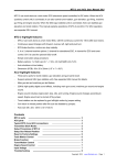
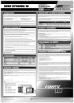
F-15 Eagle ARF
Assembly Manual
Specifications
Wingspan:
Length:
Wing Area:
Weight w/ Battery:
Weight w/o Battery:
36 in (915mm)
47 in (1195mm)
400 sq in (25.8 sq dm)
1.9–2.1 lb (0.9–1.0 kg)
2.5–3.1 oz (1.1–1.4 kg)
Table of Contents
Specifications....................................................................... 1
Introduction.......................................................................... 2
Using the Manual................................................................. 2
Contents of Kit/Parts Layout.................................................. 3
Required Radio Equipment.................................................... 3
Important Information About Motor Selection......................... 4
Motor Setup......................................................................... 4
Required Tools and Adhesives............................................... 4
Optional Accessories............................................................ 4
Warranty Information........................................................... 5
Note on Lithium Polymer Batteries......................................... 7
Warning.............................................................................. 7
Safety, Precautions, and Warnings........................................ 7
Stabilator Installation............................................................ 8
Motor and Fan Installation.................................................. 11
Fixed Gear Installation........................................................ 15
Retract Installation.............................................................. 18
Aileron Servo Installation.................................................... 25
Wing Panel Installation....................................................... 27
Receiver Installation............................................................ 28
Vertical Fin Installation........................................................ 29
Canopy Installation............................................................. 30
Control Throws................................................................... 31
Center of Gravity............................................................... 32
Range Test Your Radio........................................................ 32
Instructions for Disposal of WEEE by
Users in the European Union.................................... 32
Preflight............................................................................. 33
Flying the F-15 Eagle......................................................... 33
2008 Official AMA National Model Aircraft Safety Code.... 34
2
Introduction
The McDonnell Douglas Corporation’s F-15 Eagle was designed
to be a tactical fighter to gain and maintain air superiority in
aerial combat. The F-15 Eagle was developed out of the lessons
learned from Vietnam and the need for the United States Air
Force to have a dedicated air superiority fighter. The F-15 was
delivered into service in the late 1970s and remained in service
with the USAF for over twenty years. The F-15 was successful in
achieving air superiority through the use of avionics, weapons,
speed, and maneuverability. Its electronic systems and weaponry
could detect, track, and attack enemy aircraft while the flight
control systems would allow one person to effectively perform
air-to-air combat. E-flite has replicated the F-15 Eagle as a sport,
scale model. This military fighter model boasts the scale Edwards
Air Force Base Safety Chase trim scheme, making it a very
attractive and highly visible plane. Spend less time building and
more time flying, as this model comes out of the box fully painted
red and silver on white foam with custom decals applied. It even
includes retracts.
This high-powered model was designed around the use of two
420 DF 3800Kv motors to match with the included ducted fan
units. The low wing loading and twin ducted fans allow superior
maneuverability and acceleration to perform basic aerobatics.
While this plane is capable of flying a tight flight pattern, it can
still be flown at your local park. The wings are each reinforced
with a carbon fiber tube spar for added stability. This model also
has full flying horizontal stabilizers for pitch control and stability.
The flight characteristics and response of E-flite’s F-15 Eagle
mirror those of the full-size McDonell Douglas Eagle, down to the
aerobatic capabilities. This model was created for the ambitious
sport scale, advanced pilot looking for a versatile model capable
of park flying.
E-flite F-15 Eagle ARF Assembly Manual
Contents of Kit/Parts Layout
Large Parts:
EFL7051
EFL7052
EFL7053
EFL7054
EFL7055
EFL7056
EFL7057
EFL7058
EFL7059
EFL7060
EFL7061
EFL7062
Wing Set
Fuselage
Main Hatch
Horizontal Stab Set
Vertical Fin Set
Power Hatch
Landing Gear Set
Wheel Set
Pushrod Set
Canopy
Decal Set
Retracts
Required Radio Equipment
You will need a minimum 4-channel transmitter, crystals, receiver,
and five sub-micro servos. You can choose to purchase a
complete radio system. If you are using an existing transmitter,
just purchase the other required equipment separately. We
recommend the crystal-free, interference-free Spektrum™ DX6i
2.4GHz DSM® 6-channel system. If using your own transmitter,
we recommend the E-flite® S75 Sub-Micro Servos.
If you own the Spektrum DX6i radio, just add the AR6100E
DSM2™ 6-channel receiver and five (to eight) of our E-flite S75
Sub-Micro Servos.
Complete Radio System
SPM6600
DX6i DSM 6CH system
Or
SPMAR6100EAR6100E DSM2 6-Channel Receiver
Ultralite (for DX6i or DX7)
And
EFLRS757.5-gram Sub-Micro Servo (5–8)
(if using retracts)
EFLREX12L12-inch Servo Extension, Lightweight (2)
(Optional retracts)
EFLREX18L
18-inch Servo Extension, Lightweight (3)
EFLRYH33-inch Y-Harness, Lightweight
(3 required, 4 when installing retracts)
Motor Setup
EFLM1340DF420 Ducted Fan Brushless Outrunner,
3800Kv (2 required)
EFLA312b
40-amp Brushless ESC (2 required)
EFLB21003S
2100mAh 3-Cell 11.1V Li-Po (2 required)
Spektrum is used with permission of
Bachmann Industries, Inc.
E-flite F-15 Eagle ARF Assembly Manual
3
Required Tools and Adhesives
Tools & Equipment
EFLA250
Park Flyer Tool Assortment, 5-piece
Or Purchase Separately
EFLA257Screwdriver, #1 and #2 Phillips
(or included with EFLA250)
Hex wrench: 1.5mm
Hobby knife
Phillips screwdriver: #1
Side cutters
Painter's tape
Ruler
Rotary tool with sanding drum
6-minute epoxy
Clear tape
Hobby knife
String
Canopy glue
Threadlock
and high speed grinding bit
Optional Accessories
EFLA110
EFLC3005
EFLC505
THP21003SPL
Power Meter
Celectra™ 1- to 3-Cell Li-Po Charger
Intelligent 1- to 5-Cell Balancing Charger
2100mAh 3S 11.1V Li-Po Battery
Using the Manual
This manual is divided into sections to help make assembly
easier to understand, and to provide breaks between each major
section. In addition, check boxes have been placed next to each
step to keep track of each step completed. Steps with a single
circle () are performed once, while steps with two circles ( )
indicate that the step will require repeating, such as for a right or
left wing panel, two servos, etc.
Remember to take your time and follow the directions.
4
Warranty Information
Warranty Period
Horizon Hobby, Inc., (Horizon) warranties that the Products purchased
(the “Product”) will be free from defects in materials and workmanship
at the date of purchase by the Purchaser.
Limited Warranty
(a) This warranty is limited to the original Purchaser ("Purchaser") and
is not transferable. REPAIR OR REPLACEMENT AS PROVIDED UNDER
THIS WARRANTY IS THE EXCLUSIVE REMEDY OF THE PURCHASER.
This warranty covers only those Products purchased from an
authorized Horizon dealer. Third party transactions are not covered
by this warranty. Proof of purchase is required for warranty claims.
Further, Horizon reserves the right to change or modify this warranty
without notice and disclaims all other warranties, express or implied.
(b) Limitations- HORIZON MAKES NO WARRANTY OR
REPRESENTATION, EXPRESS OR IMPLIED, ABOUT NONINFRINGEMENT, MERCHANTABILITY OR FITNESS FOR A
PARTICULAR PURPOSE OF THE PRODUCT. THE PURCHASER
ACKNOWLEDGES THAT THEY ALONE HAVE DETERMINED THAT
THE PRODUCT WILL SUITABLY MEET THE REQUIREMENTS OF THE
PURCHASER’S INTENDED USE.
(c) Purchaser Remedy- Horizon's sole obligation hereunder
shall be that Horizon will, at its option, (i) repair or (ii) replace, any
Product determined by Horizon to be defective. In the event of a
defect, these are the Purchaser's exclusive remedies. Horizon reserves
the right to inspect any and all equipment involved in a warranty
claim. Repair or replacement decisions are at the sole discretion of
Horizon. This warranty does not cover cosmetic damage or damage
due to acts of God, accident, misuse, abuse, negligence, commercial
use, or modification of or to any part of the Product. This warranty
does not cover damage due to improper installation, operation,
maintenance, or attempted repair by anyone other than Horizon.
Return of any goods by Purchaser must be approved in writing by
Horizon before shipment.
E-flite F-15 Eagle ARF Assembly Manual
Damage Limits
HORIZON SHALL NOT BE LIABLE FOR SPECIAL, INDIRECT OR
CONSEQUENTIAL DAMAGES, LOSS OF PROFITS OR PRODUCTION
OR COMMERCIAL LOSS IN ANY WAY CONNECTED WITH THE
PRODUCT, WHETHER SUCH CLAIM IS BASED IN CONTRACT,
WARRANTY, NEGLIGENCE, OR STRICT LIABILITY. Further, in no
event shall the liability of Horizon exceed the individual price of the
Product on which liability is asserted. As Horizon has no control over
use, setup, final assembly, modification or misuse, no liability shall be
assumed nor accepted for any resulting damage or injury. By the act
of use, setup or assembly, the user accepts all resulting liability.
If you as the Purchaser or user are not prepared to accept the liability
associated with the use of this Product, you are advised to return this
Product immediately in new and unused condition to the place of
purchase.
Law: These Terms are governed by Illinois law (without regard to
conflict of law principals).
Safety Precautions
This is a sophisticated hobby Product and not a toy. It must be
operated with caution and common sense and requires some basic
mechanical ability. Failure to operate this Product in a safe and
responsible manner could result in injury or damage to the Product or
other property. This Product is not intended for use by children without
direct adult supervision. The Product manual contains instructions for
safety, operation and maintenance. It is essential to read and follow
all the instructions and warnings in the manual, prior to assembly,
setup or use, in order to operate correctly and avoid damage or
injury.
Questions, Assistance, and Repairs
Your local hobby store and/or place of purchase cannot provide
warranty support or repair. Once assembly, setup or use of the
Product has been started, you must contact Horizon directly. This will
enable Horizon to better answer your questions and service you in the
event that you may need any assistance. For questions or assistance,
please direct your email to [email protected], or call
877.504.0233 toll free to speak to a service technician.
Inspection or Repairs
If this Product needs to be inspected or repaired, please call for a
Return Merchandise Authorization (RMA). Pack the Product securely
using a shipping carton. Please note that original boxes may be
included, but are not designed to withstand the rigors of shipping
without additional protection. Ship via a carrier that provides tracking
and insurance for lost or damaged parcels, as Horizon is not
responsible for merchandise until it arrives and is accepted
at our facility. A Service Repair Request is available at www.
horizonhobby.com on the “Support” tab. If you do not have internet
access, please include a letter with your complete name, street
address, email address and phone number where you can be reached
during business days, your RMA number, a list of the included items,
method of payment for any non-warranty expenses and a brief
summary of the problem. Your original sales receipt must also be
included for warranty consideration. Be sure your name, address, and
RMA number are clearly written on the outside of the shipping carton.
Warranty Inspection and Repairs
To receive warranty service, you must include your original
sales receipt verifying the proof-of-purchase date. Provided warranty
conditions have been met, your Product will be repaired or replaced
free of charge. Repair or replacement decisions are at the sole
discretion of Horizon Hobby.
E-flite F-15 Eagle ARF Assembly Manual
5
Non-Warranty Repairs
Should your repair not be covered by warranty the repair
will be completed and payment will be required without
notification or estimate of the expense unless the expense
exceeds 50% of the retail purchase cost. By submitting the
item for repair you are agreeing to payment of the repair without
notification. Repair estimates are available upon request. You must
include this request with your repair. Non-warranty repair estimates
will be billed a minimum of ½ hour of labor. In addition you will be
billed for return freight. Please advise us of your preferred method
of payment. Horizon accepts money orders and cashiers checks, as
well as Visa, MasterCard, American Express, and Discover cards.
If you choose to pay by credit card, please include your credit card
number and expiration date. Any repair left unpaid or unclaimed
after 90 days will be considered abandoned and will be disposed of
accordingly. Please note: non-warranty repair is only available
on electronics and model engines.
Electronics and engines requiring inspection or repair should be
shipped to the following address:
Horizon Service Center
4105 Fieldstone Road
Champaign, Illinois 61822
Note on Lithium Polymer Batteries
Lithium Polymer batteries are significantly more
volatile than alkaline or Ni-Cd/Ni-MH batteries used
in RC applications. All manufacturer’s instructions
and warnings must be followed closely. Mishandling
of Li-Po batteries can result in fire. Always follow the
manufacturer’s instructions when disposing of Lithium
Polymer batteries.
Warning
An RC aircraft is not a toy! If misused, it can cause serious bodily
harm and damage to property. Fly only in open areas, preferably
at AMA (Academy of Model Aeronautics) approved flying sites,
following all instructions included with your radio.
Keep loose items that can get entangled in the propeller away
from the prop, including loose clothing, or other objects such as
pencils and screwdrivers. Especially keep your hands away from
the propeller.
All other Products requiring warranty inspection or repair should be
shipped to the following address:
Horizon Product Support
4105 Fieldstone Road
Champaign, Illinois 61822
Please call 877-504-0233 with any questions or concerns
regarding this product or warranty.
6
E-flite F-15 Eagle ARF Assembly Manual
Safety, Precautions and Warnings
Stabilator Installation
As the user of this product, you are solely responsible for
operating it in a manner that does not endanger yourself
and others or result in damage to the product or the property
of others.
Required Parts
Servo (2)
Pushrod connector (2)
Nylon nut (2)
Stabilator (right and left)
145mm pushrod w/ball end (2)
Control ball end w/setscrew (2)
Carefully follow the directions and warnings for this and any
optional support equipment (chargers, rechargeable battery
packs, etc.) that you use.
Required Tools and Adhesives
Hex wrench: 1.5mm
Hobby knife
6-minute epoxy
Threadlock
This model is controlled by a radio signal that is subject to
interference from many sources outside your control. This
interference can cause momentary loss of control so it is
necessary to always keep a safe distance in all directions around
your model, as this margin will help to avoid collisions or injury.
m 1. Remove the servo horn from the servo. Use
6-minute epoxy to glue the elevator servo in position
in the fuselage.
•A
lways operate your model in an open area away from cars,
traffic, or people.
•A
void operating your model in the street where injury or
damage can occur.
•N
ever operate the model out into the street or populated areas
for any reason.
• Never operate your model with low transmitter batteries.
•C
arefully follow the directions and warnings for this and any
optional support equipment (chargers, rechargeable battery
packs, etc.) that you use.
•K
eep all chemicals, small parts and anything electrical out of
the reach of children.
•M
oisture causes damage to electronics. Avoid water exposure
to all equipment not specifically designed and protected for
this purpose.
E-flite F-15 Eagle ARF Assembly Manual
7
m 2. Locate the stabilator and look at the rod of the
stabilizer. You will note that one side of the control rod
has a flat area ground onto the rod. This will face to the
top of the fuselage when the stabilator is installed.
m 3. Slide the appropriate stabilator into the bushing in the
fuselage. As you slide the stabilator in position, slide it
into one of the control ball ends.
8
m 4. Once the stabilator is positioned, rotate it so the
setscrew can be accessed. After applying a drop of
threadlock on the setscrew, use a 1.5mm hex wrench to
tighten the setscrew onto the flat of the control rod.
m 5. Use a hobby knife to enlarge the outer hole of a servo
arm. Install the pushrod connector and secure it, using
the nylon nut supplied with your model.
E-flite F-15 Eagle ARF Assembly Manual
m 6. Snap the ball link on the 145mm pushrod onto the
stabilizer control ball end.
E-flite F-15 Eagle ARF Assembly Manual
m 7. Slide the pushrod connector onto the pushrod wire.
After centering the elevator servo using the radio, install
the servo arm on the elevator servo. Make a small bend
in the pushrod to ensure the pushrod is straight and in
line with the control arm.
9
m 8. With the radio system on, center the stabilator using
the guide on the side of the fuselage. Tighten the setscrew
to secure the pushrod wire to the elevator servo. Make
sure to use threadlock on the setscrew to prevent it from
vibrating loose.
10
9. Repeat Steps 1 through 8 to install the remaining
elevator servo. Make note that the pushrod is bent slightly
and the servo arms of both elevator servos face the same
direction. This will make both stabilators operate in the
same direction without the need to use mixing at the
radio.
E-flite F-15 Eagle ARF Assembly Manual
Motor and Fan Installation
Required Parts
Impeller (2)
Impeller shaft (2)
Impeller shaft nut (2)
Fan housing (2)
Motor w/connectors(2)
Speed control w/connectors (2)
Fan cover
2mm x 8mm sheet metal screw (8)
18-inch extension
Y-harness
Servo (2)
2mm x 6mm machine screw (2)
2mm x 22mm sheet metal screw (2)
Required Tools and Adhesives
Hex wrench: 1.5mm
Phillips screwdriver: #1
Clear tape
Threadlock
Soldering iron
Solder
Hook and loop tape
String
Rotary tool with high speed grind bit and fine drum sander
Note: There is minimal airflow through the center of the
fuselage for ESC cooling. For this reason we have gone
to a larger amperage ESC than is really necessary. We
use the E-flite 40-amp ESC and have had no issues with
this setup in any of our test models.
m 2. Use the impeller nut to secure the impeller shaft to
the impeller. Do not tighten at this time.
m 3. Use two 2mm x 6mm machine screws and a #1
Phillips screwdriver to secure the motor in the fan
housing. Route the motor leads to the outside of the
shroud as shown.
m 1. Slide the impeller shaft onto the impeller.
Note: You might have to grind a small hole in the shroud
to accommodate your motor leads.
E-flite F-15 Eagle ARF Assembly Manual
11
m 4. Secure the impeller to the motor shaft using a 1.5mm
hex wrench and setscrew. Be sure to use threadlock when
installing the setscrew.
m 6. You can check the operation of the motor at this time.
Be very careful that you do not encounter the impeller
when checking the operation of the fan. If any rubbing
occurs, you can remove the fan rotor assembly and
work the area with a rotary tool and a fine drum sander
until all the black area is removed. Remove very little,
maintaining the circumference of the shroud. Reinstall the
impeller and run again. There should be no rubbing at
all during operation.
m 7. Slide the speed control into the opening between the
fan tunnels and into the main fuselage.
m 5. Solder the appropriate connector to the motor leads to
connect the motor to your particular speed control. Also
install the appropriate connector to the speed control to
connect the motor battery.
12
E-flite F-15 Eagle ARF Assembly Manual
m 8. Secure the fan to the fuselage using four 2mm x 8mm
sheet metal screws and a #1 Phillips screwdriver.
10. Repeat Steps 1 through 9 to install the remaining fan
assembly in the fuselage.
m 9. Secure the speed control to the side of the fuselage
using hook and loop tape.
E-flite F-15 Eagle ARF Assembly Manual
13
14
11. Secure a lightweight Y-harness to a lightweight
18-inch (457mm) servo extension.
13. Slide the servo extension into the opening between
the fan tunnels at this time.
12. Secure the elevator servos to the Y-harness using
string or a commercially available connector.
14. Use clear tape to secure the elevator servo leads
to the fan shroud. This will prevent the wiring from
interfering with the operation of the fans.
E-flite F-15 Eagle ARF Assembly Manual
15. Secure the fan cover in position using two 2mm x
22mm sheet metal screws and a #1 Phillips screwdriver.
Fixed Gear Installation
Required Parts
Main gear (right and left)
Wheel (3)
Servo w/hardware
Pushrod connector
185mm pushrod wire w/clevis
Nose gear
Spring washer (3)
2mm x 8mm sheet metal screw (12)
Nylon nut
Required Tools and Adhesives
Hex wrench: 1.5mm
Threadlock
Side cutters
Phillips screwdriver: #1
Hobby knife
m 1. Secure the main gear in the fuselage using
four 2mm x 8mm sheet metal screws and a #1
Phillips screwdriver. The gear face toward the
front of the fuselage.
Note: You might have to remove a small amount of foam
from the inside area of the Power Hatch to allow the
hatch to fit down nice and tight. This is due to the wires
from the stab servos running through this area.
E-flite F-15 Eagle ARF Assembly Manual
15
m 2. Slide the wheel onto the gear. Press a spring washer
onto the wire to secure the wheel.
16
3. Repeat Steps 1 and 2 to install the opposite main
landing gear.
4. Locate the 185mm pushrod wire. Attach the clevis
to the steering arm on the nose gear as shown. Slide
the tubing on the clevis to prevent the clevis from
opening during flight.
5. Use four 2mm x 8mm sheet metal screws and a #1
Phillips screwdriver to secure the nose gear. Note that the
spring for the gear faces to the aft of the fuselage.
E-flite F-15 Eagle ARF Assembly Manual
6. Slide the wheel onto the gear. Press a spring washer
onto the wire to secure the wheel.
7. Use a #1 Phillips screwdriver and the screws provided
with the servo to secure it in the fuselage. Make sure
to slide the servo as far to the side of the fuselage as
shown.
E-flite F-15 Eagle ARF Assembly Manual
8. Use side cutters to remove the outer hole from the
servo arm. This is done in case you will be installing
retracts later in the life of your model.
9. Use a hobby knife to enlarge the outer hole of a servo
arm. Install the pushrod connector and secure it using the
nylon nut supplied with your model.
17
10. Slide the pushrod connector onto the pushrod wire.
After centering the steering servo using the radio, install
the servo arm on the steering servo. Center the nose
wheel and secure the pushrod wire using the setscrew
and 1.5mm hex wrench.
Retract Installation
Required Parts
Nose gear retract
Main gear retract (right and left)
Wheel (3)
Spring washer (3)
Servo w/hardware (4)
2mm x 8mm sheet metal screw (12)
Pushrod connector (4)
Nylon nut (4)
185mm pushrod wire w/clevis 127mm pushrod wire w/clevis (3)
Y-harness
Required Tools and Adhesives
Hex wrench: 1.5mm
Threadlock
Side cutters
Note: You will need to bend the nose gear pushrod
slightly to achieve the correct alignment between the
servo and nose gear.
18
Phillips screwdriver: #1
Hobby knife
Special note: We use E-flite S75 servos to actuate the
retracts on the F-15. Because of this we use two channels
on the DX7 to actuate the retracts, channels 5 and 7.
We set the endpoint adjustments on these channels and
use a program mix with the Gear as the master channel
and Aux 2 as the slave channel. We reverse the Aux 2
channel to be sure it goes in the correct direction. Using
a Y-harness between the nose retract servo and one of
the main gear retract servos will enable you to ensure
correct operation of the retracts.
E-flite F-15 Eagle ARF Assembly Manual
m 1. Use a hobby knife to enlarge the outer hole of a servo
arm. Install the pushrod connector and secure it using the
nylon nut supplied with your model.
m 3. Use a hobby knife to remove the material from under
the rear wing alignment tab. This will provide the access
necessary to cut the opening for the retract servo in the
side of the fuselage.
m 2. Install the servo arm on the main gear retract servo.
The servos shown are centered. You will want an equal
amount of throw in both directions from this center
position when operating the retract servos.
E-flite F-15 Eagle ARF Assembly Manual
19
m 4. Carefully cut a hole in the side of the fuselage to
install the main gear retract servo. Make sure to allow for
clearance of the servo arm.
20
m 5. Fit the retract servo into the fuselage. It will extend
into the intake as shown. Make sure the servo fits in far
enough so the hole in the connector aligns with the center
line of the slot for the retract gear wire. Use 6-minute
epoxy to glue the servo in position.
E-flite F-15 Eagle ARF Assembly Manual
Note: Some early kits may need to have the retract units
changed for this application. Please check your retract
units with the pictures. The actuation arm should exit the
same side as the gear strut wire when retracted. If so,
skip to Step 8 on the following page of this manual.
m 7. Carefully remove the actuator arm and move it so the
actuator is on the same side as the gear strut. Install the
screws and check that the retract moves smoothly without
any binding.
m 6. Remove the three screws that hold the main gear
retract together.
E-flite F-15 Eagle ARF Assembly Manual
21
m 8. Attach the clevis from a 127mm pushrod to the retract
actuator. Slide the tubing over the clevis to secure the
clevis and prevent it from opening accidentally.
mm9. Move the retract to the "down" position. Use the radio
system to move the retract servo to the "down" position.
Mark the pushrod wire against the connector. Do not
tighten the setscrew at this time.
Important: You may need to shave the plastic retract
connector on the retract actuator arm to ensure the clevis
pin snaps closed.
22
E-flite F-15 Eagle ARF Assembly Manual
mm10. Use the radio to move the servo to the "up" position,
then move the retract linkage. Check the line made on
the wire to see if it is in the same location as it was in the
"down" position. If not, use the end point adjustment of
the radio to fine-tune the servo so the line on the pushrod
is in the same position when the servo is in both the "up"
and "down" positions. Once the servo has been adjusted,
use a 1.5mm hex wrench to tighten the setscrew and
secure the pushrod.
mm11. Use side cutters to cut the excess wire that may
interfere with the operation of the retract.
m 12. Slide the wheel onto the gear. Press a spring washer
onto the wire to secure the wheel.
E-flite F-15 Eagle ARF Assembly Manual
23
24
13. Repeat Steps 1 through 12 to install the remaining
retract and servo. You will find one main retract servo to
operate in conjunction with the nose gear and one main
retract servo will need to be plugged into an aux channel
on your radio.
14. Locate the 185mm pushrod wire. Attach the clevis
to the steering arm on the nose gear as shown. Slide the
tubing onto the clevis to prevent the clevis from opening
during flight. Connect the clevis from the 127mm pushrod
wire to the retract actuator.
15. Use four 2mm x 8mm sheet metal screws and a #1
Phillips screwdriver to secure the nose gear. Note that the
spring for the gear faces to the front of the fuselage. Slide
the wheel onto the gear. Press a spring washer onto the
wire to secure the wheel.
16. Use the screws provided with the servos to secure
them in the fuselage. Make sure to slide the servos as far
to the sides of the fuselage as shown.
E-flite F-15 Eagle ARF Assembly Manual
17. Use side cutters to remove the outer hole from
the servo arm.
18. Use a hobby knife to enlarge the outer hole of a
servo arm. Install the pushrod connector and secure it
using the nylon nut supplied with your model.
E-flite F-15 Eagle ARF Assembly Manual
19. Slide the pushrod connector onto the pushrod wire.
After centering the steering servo using the radio, install
the servo arm on the steering servo. Center the nose
wheel and secure the pushrod wire using the setscrew
and 1.5mm hex wrench. Using a Y-harness, plug the
nose gear retract servo into the gear channel. Repeat
Steps 9, 10 and 11 to adjust the nose gear retract servo.
You should find the nose retract servo will be very similar
in endpoints to one of the main retract servos.
25
Aileron Servo Installation
Required Parts
Servo (2)
Pushrod connector (2)
Nylon nut (2)
Servo tape covers
Required Tools and Adhesives
Hex wrench: 1.5mm
Hobby knife
Wing panel (right and left)
75mm pushrod w/clevis (2)
Control horn (2)
Carbon spar tape covers
m 2. Install the servo arm on the aileron servos. Make sure
to center the aileron servos using the radio system before
installing the servo arms.
6-minute epoxy
m 1. Use a hobby knife to enlarge the outer hole of a servo
arm. Install the pushrod connector and secure it using the
nylon nut supplied with your model.
m 3. Use 6-minute epoxy to glue the aileron servo into
the wing. Note that the servo arm faces toward the
aileron. Press the servo lead into the channel in the
wing as shown.
26
E-flite F-15 Eagle ARF Assembly Manual
m 4. Slide a 75mm pushrod wire into the hole in the
connector. Use a hobby knife to cut a 2mm wide
slot in the aileron near the hinge line using the wire
as a guide. Keep the wire perpendicular to the servo
while cutting the slot.
m 6. Connect the clevis to the control horn. With the
aileron and aileron servo centered, tighten the setscrew
in to connector with a 1.5mm hex wrench to secure the
pushrod wire.
m 7. Use the supplied tape to cover the aileron servo and
wire as shown. You may now cover the carbon spar with
the white and orange tape.
m 5. Use 6-minute epoxy to glue the control horn in the
aileron as shown.
E-flite F-15 Eagle ARF Assembly Manual
8. Repeat Steps 1 through 7 to install the remaining
aileron servo and linkage.
27
Wing Panel Installation
Required Parts
Assembled wing panel (right and left)
Assembled fuselage
Required Tools and Adhesives
6-minute epoxy
m 2. Position the wing so it is parallel to your work surface
when viewed from the front of the aircraft. Makle sure
the fuselage is parallel to the work surface as well. Use
6-minute epoxy to glue one wing panel to the fuselage.
Use painter's tape to keep the wing tight against the
fuselage while the epoxy cures.
Painter's tape
m 1. Test fit the wing panel to the fuselage. You will need to
cut a hole to route the aileron servo lead into the fuselage
as shown.
28
3. Repeat Steps 1 and 2 to attach the remaining wing
panel to the fuselage. Make sure the alignment of the
second wing panel matches that of the first panel so the
aircraft has an equal amount of dihedral for both right
and left panels. If the dihedral does not match, it may
require a lot of trim to correct and will not provide the
best flight performance.
E-flite F-15 Eagle ARF Assembly Manual
Receiver Installation
2. Secure the receiver on the top side of the same
plywood plate the nose gear is attached to, using hook
and loop tape. Plug the servo leads for the elevators,
ailerons, retracts, nose gear steering and speed controls
into the receiver. Use a Y-harness between each of the
speed controls, between the aileron servo extensions and
one of the main and nose gear retracts.
3. Use clear tape to secure the servo leads neatly
inside the battery compartment. Doing so will make the
installation and removal of the batteries much easier.
Required Parts
Assembled airframe
18-inch (457mm) lightweight servo extension (2) (aileron)
12-inch (305mm) lightweight servo extension (2) (main retract)
Y-harness (2) (3 if retracts are installed)
Required Tools and Adhesives
Clear tape
String
Hook and loop tape
1. Secure an 18-inch (457mm) lightweight servo
extension to each of the aileron servos. If retracts
have been installed, secure 12-inch (305mm)
extensions to each of the retract servos. Use clear
tape to tape the leads and extensions inside the intake.
You may use string to pull the extensions through the
center of the model.
E-flite F-15 Eagle ARF Assembly Manual
29
Vertical Fin Installation
Required Parts
Assembled airframe
Vertical fin (right and left)
2. Check the alignment between the right and left fins.
They should be parallel to each other, and perpendicular
to the top of the fuselage. If the alignment is correct, use
6-minute epoxy to glue the fins to the fuselage.
Required Tools and Adhesives
6-minute epoxy
30
1. Position the right and left fins in the slots on the top of
the fuselage.
E-flite F-15 Eagle ARF Assembly Manual
Canopy Installation
Required Parts
Assembled airframe
Canopy
Required Tools and Adhesives
Painter's tape
2. Slide the canopy catch forward and press the
canopy hatch down. Release the catch into position
to secure the canopy.
3. Use canopy glue to glue the canopy to the canopy
hatch. Use painter's tape to keep the canopy in position
until the glue fully cures.
Canopy hatch
Canopy glue
1. Slide the tab at the back of the canopy hatch
underneath the lip of the fuselage as shown.
E-flite F-15 Eagle ARF Assembly Manual
31
Control Throws
1
. Turn on the transmitter and receiver of your F-15 Eagle.
Check the movement of the rudder using the transmitter.
When the stick is moved right, the rudder should also move
right. Reverse the direction of the servo at the transmitter if
necessary.
2
. Check the movement of the elevator with the radio system.
Moving the elevator stick down will make the airplane
elevator move up.
3
. Check the movement of the ailerons with the radio system.
Moving the aileron stick right will make the right aileron
move up and the left aileron move down.
4
. Use a ruler to adjust the throw of the elevator, ailerons
and rudder. Adjust the position of the pushrod at the control
horn to achieve the following measurements when moving the
sticks to their endpoints.
Note: Measurements are taken at the widest point on
the surface.
32
Ailerons
Low Rate: 1/2-inch (12mm) (Up/Down)
High Rate:1-inch (25mm) (Up/Down)
Elevator
Low Rate: 3/4-inch (19mm) (Up/Down)
High Rate:1-inch (25mm) (Up/Down)
Nose Wheel Steering
Low Rate: 10 degrees (left/right)
High Rate:25 degrees (left/right)
These are general guidelines measured from our own flight tests.
You can experiment with higher rates to match your preferred
style of flying.
Once all the control throws have been set, make sure to slide
the clevis retainers over the clevises to prevent them from
opening accidentally.
Note: The following image shows the movement of the
stabilator to the "up" position.
E-flite F-15 Eagle ARF Assembly Manual
Center of Gravity
An important part of preparing the aircraft for flight is properly
balancing the model.
Caution: Do not inadvertently skip this step!
The recommended Center of Gravity (CG) location for the
F-15 Eagle ARF is 3 3/8-inch (85mm) back from the leading edge
of the wing. Mark the location of the CG on the top of the wing.
You will notice two small dot stickers have been applied for your
reference.
Please balance your model while it is upright with the batteries
installed. If using retracts, balance with the gear retracted.
If using (2) Thunder Power 2100 Pro-Lite Li-Po batteries, the
balance should come out very close to the mark. With the model
inverted, lift the model at the mark using your fingertips, or use
a commercially available balancing stand. The model will rest
level or slightly nose down when balanced correctly. Adjust the
position of the motor battery, or add weight to the nose or tail
if necessary to achieve the correct CG. Please understand that if
you use a different Li-Po battery than the one included, you will
need to rebalance the model to verify the Center of Gravity.
After the first flights, the CG position can be adjusted for your
personal preference.
E-flite F-15 Eagle ARF Assembly Manual
Range Test Your Radio
1. Please consult your radio instructions for complete
range testing instructions.
2. Double-check that all controls (aileron, elevator, rudder
and throttle) move in the correct direction.
3. Be sure that your transmitter batteries are fully
charged, per the instructions included with your radio.
Instructions for Disposal of WEEE by
Users in the European Union
This product must not be disposed of with other waste. Instead, it
is the user’s responsibility to dispose of their waste equipment by
handing it over to a designated collection point for the recycling
of waste electrical and electronic equipment. The separate
collection and recycling of your waste equipment at the time of
disposal will help to conserve natural resources and ensure that
it is recycled in a manner that protects human health and the
environment. For more information about where you can drop
off your waste equipment for recycling, please contact your local
city office, your household waste disposal service or where you
purchased the product.
33
Preflight
Check Your Radio
Before going to the field, be sure that your batteries are fully
charged per the instructions included with your radio. Charge
both the transmitter and receiver pack for your airplane. Use the
recommended charger supplied with your particular radio system,
following the instructions provided with the radio. In most cases,
the radio should be charged the night before going out flying.
Before each flying session, be sure to range check your radio.
See your radio manual for the recommended range and
instructions for your radio system. Each radio manufacturer
specifies different procedures for their radio systems. Next, start
the motor. With the model securely anchored, check the range
again. The range test should not be significantly affected. If it is,
don’t attempt to fly! Have your radio equipment checked out by
the manufacturer.
Note: Keep loose items that can get entangled in
the propeller away from the prop. These include
loose clothing, or other objects such as pencils and
screwdrivers. Especially keep your hands away from
the propeller.
Double-check that all controls (aileron, elevator, rudder and
throttle) move in the correct direction.
Check the radio installation and make sure all the control
surfaces are moving correctly (i.e. the correct direction and with
the recommended throws). Test run the motor and make sure
it transitions smoothly from off to full throttle and back. Also
ensure the engine is installed according to the manufacturer’s
instructions, and it will operate consistently.
Flying the F-15 Eagle
Flying the F-15 Eagle is about as easy as it can be with a small
ducted fan. The large wing and full flying stabs make for a very
maneuverable platform that is capable of some very slow high
alpha flight.
If you elected to leave the gear off the model to maintain the
lightest possible weight, you will need to hand launch the model.
Using the two cheater holes in the bottom of the fuselage, this
becomes a nice hand hold where you can grab hold of the model
for a hand launch. To hand launch the model, all you need to do
is apply full power and throw the model into the wind at a slightly
nose up attitude. The plane will fly out without hesitation.
To take off from the ground, apply a small amount of elevator
and full power. Steer the model straight with the nose gear.
The plane should rotate within about 150 feet. Once you have
rotated, ease off the elevator and continue to climb out at a nice
angle of attack.
The model tracks very well through all basic aerobatic
maneuvers. Inverted flight, rolls and loops are all accomplished
with ease. To set up for landing, all that's needed is to lower the
landing gear (if retracts are installed) and power back. As you lift
the nose of the model, you will find the model behaves very well
and it is easy to establish a shallow nose-high descent rate which
can be managed with power. Touchdowns are nose high and the
roll outs are straight down the runway. We hope you enjoy flying
the F-15 Eagle as much as we do.
Check all the control horns, servo horns, and clevises to make
sure they are secure and in good condition. Replace any items
that would be considered questionable. Failure of any of these
components in flight would mean the loss of your aircraft.
34
E-flite F-15 Eagle ARF Assembly Manual
2008 Official AMA National
Model Aircraft Safety Code
GENERAL
1) I will not fly my model aircraft in sanctioned events, air shows
or model flying demonstrations until it has been proven to be
airworthy by having been previously, successfully flight tested.
2) I will not fly my model higher than approximately 400 feet within 3
miles of an airport without notifying the airport operator. I will give
right-of-way and avoid flying in the proximity of full-scale aircraft.
Where necessary, an observer shall be utilized to supervise flying
to avoid having models fly in the proximity of full-scale aircraft.
3) Where established, I will abide by the safety rules for the flying
site I use, and I will not willfully or deliberately fly my models in a
careless, reckless and/or dangerous manner.
4) The maximum takeoff weight of a model is 55 pounds, except
models flown under Experimental Aircraft rules.
5) I will not fly my model unless it is identified with my name and
address or AMA number on or in the model. (This does not apply
to models while being flown indoors.)
6) I will not operate models with metal-bladed propellers or with
gaseous boosts, in which gases other than air enter their internal
combustion engine(s); nor will I operate models with extremely
hazardous fuels such as those containing tetranitromethane or
hydrazine.
RADIO CONTROL
1) I will have completed a successful radio equipment ground range
check before the first flight of a new or repaired model.
2) I will not fly my model aircraft in the presence of spectators until I
become a qualified flier, unless assisted by an experienced helper.
3) At all flying sites a straight or curved line(s) must be established
in front of which all flying takes place with the other side for
spectators. Only personnel involved with flying the aircraft are
allowed at or in front of the flight line. Intentional flying behind the
flight line is prohibited.
E-flite F-15 Eagle ARF Assembly Manual
4) I will operate my model using only radio control frequencies
currently allowed by the Federal Communications Commission.
(Only properly licensed Amateurs are authorized to operate
equipment on Amateur Band frequencies.)
5) Flying sites separated by three miles or more are considered safe
from site-to-site interference, even when both sites use the same
frequencies. Any circumstances under three miles separation
require a frequency management arrangement, which may be
either an allocation of specific frequencies for each site or testing
to determine that freedom from interference exists. Allocation plans
or interference test reports shall be signed by the parties involved
and provided to AMA Headquarters.
ocuments of agreement and reports may exist between (1) two
D
or more AMA Chartered Clubs, (2) AMA clubs and individual
AMA members not associated with AMA Clubs, or (3) two or
more individual AMA members.
6) For Combat, distance between combat engagement line
and spectator line will be 500 feet per cubic inch of engine
displacement. (Example: .40 engine = 200 feet.); electric motors
will be based on equivalent combustion engine size. Additional
safety requirements will be per the RC Combat section of the
current Competition Regulations.
7) At air shows or model flying demonstrations, a single straight line
must be established, one side of which is for flying, with the other
side for spectators.
8) With the exception of events flown under AMA Competition rules,
after launch, except for pilots or helpers being used, no powered
model may be flown closer than 25 feet to any person.
9) Under no circumstances may a pilot or other person touch a
powered model in flight.
35
12847
© 2008 Horizon Hobby, Inc.
4105 Fieldstone Road
Champaign, Illinois 61822
(877) 504-0233
horizonhobby.com
E-fliteRC.com