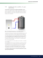
Download Work Pro ZENITH 600 Technical data
Transcript
162 105 20-2 2013-10-02 Providing sustainable energy solutions worldwide Installation and Maintenance Manual CTC EcoZenith i550 Pro Installation and Maintenance Manual CTC EcoZenith i550 Pro 162 105 20-2 2013-10-02 General Information Table of Contents GENERAL INFORMATION 4 Check list_____________________________________________________________________ 6 Important to remember!______________________________________________ 7 Safety Instructions______________________________________________________ 7 Scope of delivery_________________________________________________________ 8 1. CTC EcoZenith i550 Pro design __________________________ 9 10. Operation and Maintenance______________________________ 77 11.Troubleshooting/measures_________________________________ 79 11.1 Information messages_____________________________________ 81 11.2 Alarm messages_____________________________________________ 82 FOR THE INSTALLER 12. Transportation, unpacking and installation_______ 84 2. CTC EcoZenith i550 Pro function______________________ 10 12.1Transportation _______________________________________________ 84 2.1 Heating System______________________________________________ 11 12.2Unpacking_____________________________________________________ 84 2.2DHW____________________________________________________________ 12 12.3 Fitting rear insulation and plastic top cover__________ 84 2.3 Heat pump____________________________________________________ 13 2.4 Wood Boiler___________________________________________________ 16 2.5 Additional boiler (pellets, oil, gas, electricity)________ 17 2.6 Solar Energy__________________________________________________ 18 13. Pipe installation__________________________________________________ 86 14. Schematic diagram____________________________________________ 98 15. Parts list____________________________________________________________ 100 16. Electrical installation________________________________________ 102 2.7 Recharging Bedrock/Ground____________________________ 19 16.1 Positioning of electrical components_________________103 2.8 External Hot Water Tank__________________________________ 20 16.2 Heat pump power supply________________________________104 2.9Pool _____________________________________________________________ 20 16.3 Communication between the EcoZenith and CTC 2.10 External Buffer Tank________________________________________ 21 EcoAir/CTC EcoPart______________________________________104 2.11 Cooling CTC EcoComfort________________________________ 23 16.4 Low voltage 230V /400V (Heavy current)___________104 3. The House Heating Curve__________________________________ 24 4.DHW____________________________________________________________________ 27 5. Technical data_____________________________________________________ 29 6.Measurements____________________________________________________ 30 7. Menu overview____________________________________________________ 31 16.5 Sensor (Safety Extra-Low Voltage (SELV))__________113 7.1 Room temp.__________________________________________________ 32 7.2DHW____________________________________________________________ 32 7.3Operation______________________________________________________ 33 7.4 Installer (Time/Language – Settings)___________________ 34 7.5 Installer (Define system)___________________________________ 36 7.6 Installer (Service)_____________________________________________ 38 8. Parameter list______________________________________________________ 40 9. Detail Description Menus___________________________________ 42 16.6 Night reduction/ripple control___________________________117 16.7 Current sensor connection______________________________117 16.8 Settings made by the installation electrician_______118 17. Installation of optional immersion heater________ 119 18. Installation of additional boiler_________________________ 120 19. Parts list Wiring diagram__________________________________ 121 20. Wiring diagram main card 3x400V___________________ 122 21. Wiring diagram main card 1x230V___________________ 124 22. Wiring diagram for expansion card_________________ 126 23. Resistances for sensors___________________________________ 127 24. First start___________________________________________________________ 128 24.1 Before first start_____________________________________________128 9.1 Start menu____________________________________________________ 42 24.2 First start______________________________________________________129 9.2 Room temp.__________________________________________________ 43 Declaration of Conformity_______________________________________ 130 9.3DHW____________________________________________________________ 45 9.4Operation______________________________________________________ 46 9.5Installer_________________________________________________________ 54 Quick reference Fill in the information below. It may come in useful if anything should happen. Product: Manufacturing number: Installer: Name: Date: Tel. no.: Electrical installer: Name: Date: Tel. no.: No liability is accepted for any misprints. We reserve the right to make design changes. 4 84 Main components_____________________________________________ 9 1.1 CTC EcoZenith i550 Pro General Information Congratulations on buying your new product You have just bought a CTC EcoZenith i550 Pro, which we hope you will be very pleased with. In the following pages you can read about how to operate and maintain your product. One part contains general information and one part has been written for the installer. Keep this manual containing the installation and maintenance instructions. You will be able to enjoy the benefits of your EcoZenith for many years, and this manual provides all the information you will need. The Complete System The CTC EcoZenith i550 Pro is a complete system which meets your home’s heating and hot water requirements. It is equipped with a unique control system that monitors and controls your entire heating system regardless of how you choose to tailor it. The CTC EcoZenith i550 Pro has a control system that: • monitors all hot water and heating system functions; • monitors and controls your heat pump, solar panels, additional heat, buffer tank, pool, etc.; • allows for individual settings; • indicates desired values, for instance, temperatures and energy consumption; Your CTC EcoZenith i550 Pro has built-in finned copper coils which provide plenty of hot water and another finned copper coil to handle the heat from solar panels. The product also has a so-called cellar heat feature during the summer and a floor feature which maximizes the primary flow temperature. Using the integrated night reduction function, you can set and change the temperature in the property during a 24-hour period, day by day, in blocks or as a vacation function. Service-friendly Easily accessible electrical components, along with effective troubleshooting functions in the control program, make the EcoZenith easy to service. It is supplied with a room sensor as standard, which is equipped with LED lights that flash in the event of a fault. The EcoZenith is fully designed to work with the CTC EcoAir 400 series outdoor air heat pump, the CTC EcoPart 400 series bedrock/ground source heat pump, solar panels, water-jacketed stove and an additional boiler where present. The EcoZenith can control a number of combinations and provide you with an extremely flexible, eco-friendly and energy-saving heating system. • facilitates settings in a simple and structured manner. CTC EcoZenith i550 Pro 5 General Information Check list The check list must be completed by the installer. • In the event of a service, this information may be called for. • Installation must always be done according to the installation and maintenance instructions. • Installation must always be carried out in a professional manner. • Following installation, the unit should be inspected and checked for functionality. Following installation, the unit must be inspected and functional checks performed as indicated below: Pipe installation EcoZenith filled, positioned and adjusted in the correct manner according to the instructions. EcoZenith positioned so that it can be serviced. Capacity of the charge/radiator pump (depending on type of system) for the flow required. Open radiator valves and other relevant valves. Tightness test. Bleed the system. Safety valve function test. The waste pipe is connected to the draining gutter. Electrical installation Compressor, direction of rotation (if heat pump installed). Power switch Correct tight wiring Requisite sensors for applicable system Outdoor sensor Room sensors (optional) Accessories Information for the customer (adapted to current installation) Start-up with customer/installer. Menus/controls for selected system Installation and maintenance manual supplied to the customer Checks and filling, heating system Trimming information, heat curve Alarm information Mixing valve Safety valve function test Warranty conditions Information on procedures for fault registration 6 ______________________________________ ______________________________________ Date / Customer Date / Installer CTC EcoZenith i550 Pro General Information Important to remember! Check the following points in particular at the time of delivery and installation: • The CTC EcoZenith i550 Pro must be transported and stored in an upright position. When moving the product, it can be placed temporarily on its back. • Remove the packaging and check before installation that the product has not been damaged in transit. Report any transport damage to the carrier. • Place the CTC EcoZenith i550 Pro on a solid foundation, preferably made of concrete. If the product needs to be placed on a soft carpet, base plates must be placed under the adjustable feet. • Remember to leave a service area of at least 1 m in front of the product. Space is also needed around the product for installation of insulation and plastic top cover. See the chapter on Transportation, unpacking and installation in the section for the installer. The CTC EcoZenith i550 Pro must not be lowered beneath floor level. • Check for missing parts. • The product must not be installed where the ambient temperature is higher than 60°C. Safety Instructions The following safety instructions must be observed when handling, installing and using the heat pump: • All installation must be carried out by a qualified person in accordance with applicable regulations. • The product is only intended for vertical installation. • Close the safety switch before doing any work on the product. • Do not soak the product with water or any other liquid. • When handling the product with a hoist ring or similar device, make sure that the lifting equipment, eyebolts etc. are not damaged. Never stand under the hoisted product. • Never jeopardize safety by removing bolted covers, hoods or similar. • Never jeopardize safety by deactivating safety equipment. • Any work on the product should be done by authorised personnel only. • Safety valve check: – The safety valve for the boiler/system and hot tap water must be checked on a regular basis. See the chapter on Operation and maintenance. CTC EcoZenith i550 Pro 7 General Information Scope of delivery Standard delivery • Multitank CTC EcoZenith i550 Pro • Additional package with: –– Installation and Maintenance Manual –– Outdoor sensor –– Room sensor –– Safety valve 9 bar (tap water) –– Safety valve 2.5 bar (radiator system) –– Drainage valve –– Adapter between the drainage valve and the connection sleeve –– Sensor, 2 off (to and from pipes) –– Current sensor, 3 off –– Cover washer for connections, upper and lower tank, 8 off –– Cover washer for solar coil connections, 2 off –– Insulation for connection sleeves that are not used –– Sensor labelling –– Screw 4.2 x 14 graphite grey, 25 off + 2 extra –– Screw 4.2 x 14 zinc grey, 4 off + 2 extra • Additional package with rear insulation sections and plastic top 8 CTC EcoZenith i550 Pro General Information 1. CTC EcoZenith i550 Pro design This chapter illustrates the main components and describes the subsystems which, in different configurations, form part of the main system. For more information about the EcoZenith configurations, refer to the “Pipe connections” chapter. 1.1 Main components Bivalent Mixing Valve The automated mixing valve ensures that an even heat is continuously supplied to the radiator system. The valve has double ports and takes the warm radiator water from the solar and heat pump heated water in the lower part of the tank first. Control System The EcoZenith is equipped with an intelligent control system which controls and monitors all parts of the heating system. The EcoZenith ensures that the most economical way of heating the house and the hot water is prioritised. Finned Coil for Hot Water The EcoZenith is equipped with a well dimensioned finned copper coil and does not contain any heater which can rust. A low temperature can be maintained without the risk of legionella bacteria. Immersion heaters in Upper Part of Tank Built-in upper immersion heater. When connected to a heat pump, the immersion heater acts as additional heat. (The uppermost immersion heater is an accessory). Lower tank In the lower part of the tank, hot water is preheated in the coil by the solar- or heat pump-heated water. Solar Coil Connections The well dimensioned, 10 m long, finned coil can be connected directly to the solar panels. Lower immersion heater Built-in lower immersion heater. Fresh Water Connections Here you connect the property’s fresh water connections. The cold water is fed down to the lower part of the coiling, where it is preheated. Top Connection For connection of expansion vessel and/or safety valve. Upper tank In the upper part of the tank, the warm water in the coil is heated up to the desired temperature. Upper Tank Connections The upper part of the tank, the additional part, can be heated by heat pump and connected to heat sources such as electric, gas, oil and pellet boilers. Heat from a wood boiler is delivered to this part. Connections are placed symmetrically on both sides of the tank. Heat Distribution Pipes The heat distribution pipes ensure that heat from the solar coil is directed to the upper tank and that, after hot water is drawn off, cooled water is directed to the lower part of the tank to be heated again by solar energy or heat pump. Insulated tank divider Between the tank’s upper and lower tank is an insulated tank divider. This provides high temperatures in the upper tank for good hot water capacity and low temperatures in the lower tank for best operating economy. Lower Tank Connections The heat pump and solar system are connected to the lower tank. Water to be heated by wood boiler is taken from here, and heat which is to be stored in a buffer tank is also taken from this part. Connections are placed symmetrically on both sides of the tank. Insulation The tank is insulated by 90-mmthick molded polyurethane foam for minimum heat loss. CTC EcoZenith i550 Pro 9 General Information 2. CTC EcoZenith i550 Pro function The CTC EcoZenith i550 Pro is a multi-tank with almost unlimited possibilities. ! The EcoZenith is intended for houses and properties with water-borne heat. The multi-tank features include intelligent control, a water volume of 540 litres, bivalent mixing valve, two hot water coils, a solar coil and two 9 kW immersion heaters giving a total of 18 kW. You can easily add another immersion heater as an accessory to provide total power of 27 kW, controlled by the EcoZenith. The control is specially adapted to simultaneously control up to three of CTC’s heat pumps, but it will also control and optimise the following: • Energy storage in buffer tanks • Three heating circuits simultaneously • Solar panels and bore hole recharging • Cooling (passive cooling), floor or fan convector • Hot water circulation with time control • Charging of extra domestic hot water tank • Connected wood boiler, gas/oil boiler and pellets upper tank • Pool The CTC EcoZenith i550 Pro is divided into two tanks which are isolated from each other in order to be able to hold different temperatures in the two tanks. This provides for optimal function and operating economy. The upper and the lower tanks are connected by heat distribution pipes which are especially developed for the solar energy to be able to form layers optimally in the entire volume of the tank and act as flow-through of the tank on wood operation, for instance. See figure. See also Immersion heaters Menu in the Detail Description Menus chapter (“Installer/Settings/Electric heaters”) See also Lower tank Menu in the Detail Description Menus chapter: “Installer/Settings/Lower tank” 10 CTC EcoZenith i550 Pro lower tank The CTC EcoZenith is well-insulated with 90 mm PUR and is well provided with connection options on both sides, ensuring clean and easy pipe installations. It also provides for extensions and additions to the system in the future. Remember that menus which have not been defined cannot be seen. General Information 2.1 Heating System The EcoZenith is equipped with a bivalent mixing valve, which always delivers an even temperature, without variation, to the heating system. The bivalent mixing valve is controlled by an outdoor sensor and, optionally, by a room sensor. When operating with outdoor sensor alone, the desired curve inclination and adjustment are set. These values differ from home to home and should be adjusted to suit your needs. A room sensor that is correctly positioned provides more comfort and more heating system savings. The room sensor picks up the current indoor temperature and adjusts the heat, for example when it is windy outside and the house is losing heat, which the outdoor sensor is unable to register. During solar insolation, or other instances when heat builds inside the house, the room sensor can also reduce the heat, thus saving energy. Another way to save energy is to use the night reduction function, which reduces the indoor house temperature at certain times or periods, for example during the night or when you are away on holiday. The EcoZenith can control up to three heating systems, each with its own room sensor. For instance, one radiator circuit plus two floor heating circuits. The bivalent mixing valve always attempts to use the energy from the lower tank first; this is especially important when a heat pump or solar panel is connected to the EcoZenith. This ensures the system delivers good operating economy and that the upper tank stays warm to provide an abundance of hot water. See also Heating system Menu in the Detail Description Menus chapter (Installer/Settings/Heating circuit 1-3). See also Room temperature Menu in the Detail Description Menus chapter. You access the menu directly from the main menu. CTC EcoZenith i550 Pro 11 General Information 2.2 DHW The final heating of the hot water takes place in the upper tank. It also acts as additional heating for the heating system when the lower tank is not sufficient. The hot water is heated using two finned copper tube coils of approx. 40 metres connected in parallel. The coils preheat the water in the lower tank and the water reaches maximum temperature in the upper tank. The low inner volume and high rate of water turnover in the copper coil prevents build-up of bacteria. With double coils, high draw-off flows can be obtained, as the heat conduction area is finned, on the inside as well as the outside. For more information on settings and tips, please see the DHW chapter. 2.2.1 Hot Water Circulation The hot water coil has a connection for hot water charging, which can be used to heat an external cold water tank when greater tap capacity of DHW is required, and allows connection of hot water circulation. This means that hot water is always available at the tap. To save energy the HWC pump can be time controlled from the EcoZenith. See also Upper tank Menu in the Detail Description Menus chapter (Installer/Settings/Upper tank). 12 CTC EcoZenith i550 Pro General Information 2.3 Heat pump The EcoZenith is designed with two parts in order to ensure the heat pump operates to maximum possible economy. The heat pump is connected via two diverting valves to the EcoZenith and ensures that the heat is directed into the upper and lower tanks, respectively. For instance, when the heat pump pumps towards the upper tank, the diverting valves send the flow to the two uppermost connections, so that the flow enters port 1 and exits through port 2. The heat pump operates in two different ways, depending on whether it is the upper tank or the lower tank being charged. 2.3.1 Upper tank port 1 upper tank port 2 lower tank The final hot water heating takes place in the upper tank. This means that, with a high upper tank temperature, an ample hot water supply is obtained. The upper tank has a factory-set stop temperature of 55°C, which means that the heat pump will work to achieve this temperature in the upper tank. When hot water is being drawn off and the temperature in the upper tank falls to 5°C below the stop temperature, the heat pump starts up and raises the temperature towards the set stop temperature. The stop temperature can be adapted to hot water needs and to the heat pump model installed. When there is also a need for heat in the house, the diverting valves will automatically reverse direction and the heat pump continues to heat the lower tank as soon as the stop temperature 55°C in the upper tank has been reached. If the upper tank has not reached the stop temperature 55°C within the factory-set 20 minutes of charging, the diverting valves reverse the direction and the heat pump charges the lower tank. This is to prevent loss of temperature in the heating system. See also Upper tank Menu in the Detail Description Menus chapter (Installer/Settings/Upper tank) CTC EcoZenith i550 Pro 13 General Information 2.3.2 Lower tank In the lower tank the heat pump operates to provide heat to the heating system. Heat pump operation is of so-called floating condensation type. However, the lower tank never drops below the set lowest temperature. Floating condensation operation is where the heat pump heats to the temperature required by the heating system. This temperature varies depending on the outdoor temperature and which set inclination and adjustment (the heat curve for the house) has been chosen. If a room sensor is installed, this will affect the temperature required in the system. During spring and autumn, when it is not so cold outside, a lower temperature is needed for the heating system, but during winter a higher temperature is needed to maintain the desired indoor temperature. Savings from a heat pump are directly linked to the COP value. COP means the output divided by the supplied power. COP 4 therefore means, for instance, that the heat pump delivers 4 kW and uses 1 kW ( 4 = 4 ) 1 The lower the temperature the heat pump needs to deliver, the higher the COP value obtained from the heat pump, as this will involve the compressor working to better advantage. Therefore, the heat pump heats only to the lower tank temperature the heating system requires. This saves compressor life and maximizes operating economy. The immersion heater, which is factory installed in the lower tank, is blocked as long as the heat pump is operating. The immersion heater is only brought into use if the heat pump is blocked for any reason. See also Lower tank Menu in the Detail Description Menus chapter (Installer/Settings/Lower tank) and the DHW chapter. 14 CTC EcoZenith i550 Pro General Information 2.3.3 More Than One Heat Pump. If more than one heat pump is installed, heat pumps two and three are connected to the lower tank only. Only one of the heat pumps alternates between DHW and heating operation. The Ecozenith’s controller equalises the operating time between the heat pumps so as to maximise heat output and minimise the load on them. If the heat pump which starts first does not manage to get the temperature up to the desired value, the second starts after a factory-set period of 30 minutes, and then the third after another 30 minutes. See also Heat pump Menu in the Detail Description Menus chapter (Installer/Settings/Heat pump A1-A3) 2.3.4 Different Heat Pumps The EcoZenith can control different types of heat pumps, the CTC EcoAir (outdoor air heat pump) and the CTC EcoPart (bedrock/ground source heat pump). The desired outdoor temperature at which the CTC EcoAir is prioritised over the CTC EcoPart is set in the “Installer/Settings/Heat pumps 1, 2, 3” menu under “Prio EcoAir/EcoPart”. This means that the operating economy can be maximised, as at a high outdoor temperature a greater energy yield is obtained from the CTC EcoAir than from the CTC EcoPart. This combination is excellent in installations where, for example, bedrock/ ground source heat pumps are designed with too much focus on “saving” etc. An air/water heat pump may then be used to allow the bedrock more time to “recover” and to provide increased output of the installation. Remember that only one heat pump can be connected via the diverting valves and charge hot water in the upper tank. See also Heat pump Menu in the Detail Description Menus chapter (Installer/Settings/Heat pump A1-A3) CTC EcoZenith i550 Pro 15 General Information 2.3.5 Speed-controlled charge pump (accessory from CTC) Each heat pump should be provided with a separate charge pump that is controlled in tandem with its respective heat pump. If a speed-controlled PVM charge pump (accessory from CTC) is connected to the heat pump and controlled from the EcoZenith, the flow will be automatically set without any adjustment needed via the control valve. In the upper tank the speed of the charge pump will be controlled so that the heat pump always delivers its highest possible temperature into the top of the EcoZenith. This provides for quick access to hot water when the heat pump starts. Towards the lower tank the speed-controlled charge pump will work for a fixed difference between flow and return from the heat pump. If a speed-controlled charge pump is not installed, the flow has to be adjusted manually, and the difference between incoming and outgoing water from the heat pump will vary, depending on the operation conditions during the year. In cases where an air/water heat pump is installed and the outdoor temperature is less than +2°C, the charge pumps are started in order to protect against frost. If a speed-controlled charge pump is installed, the pump will only work at 25% of its maximum capacity. This provides for increased savings on the charge pump’s operating economy, and the heat losses in the EcoZenith are reduced compared to a conventional on/off charge pump. See also Heat pump Menu in the Detail Description Menus chapter (Installer/ Settings/Heat pump A1-A3) 2.4 Wood Boiler The EcoZenith can be connected to a wood boiler, such as the CTC V40. The primary flow from the wood boiler is connected to the top of the EcoZenith and the return flow to the wood boiler is connected to the lowest connection on the lower tank. When firing is started and the flue gas sensor reaches a set value (menu “Installer/Settings/Wood boiler” factory-set “100°C”), the control goes into wood operation status when the temperature of the lower tank is above or equal to its reference value (setpoint). When wood operation is active, a heat pump or additional heat are not used for heating the EcoZenith. When the flue gas sensor is below the set value, wood operation status is interrupted. It is recommended the wood boiler be provided with a charge system. A charge system such as Laddomat 21 is recommended for optimum performance. The charge pump in the charging system has to be controlled from the wood boiler. In special cases, such as operation with a waterjacketed stove, the charge pump may be controlled from the EcoZenith without installing a charge system. See also Wood Boiler Menu in the Detail Description Menus chapter (Installer/Settings/Wood boiler) 16 CTC EcoZenith i550 Pro General Information 2.5 Additional boiler (pellets, oil, gas, electricity) The EcoZenith can control an external additional boiler (pellets, oil, gas, electricity). The additional boiler is connected to the upper tank. Use the menu to select whether the external additional boiler should have high or low priority. If high priority is selected, the external additional boiler is activated before the immersion heater(s); when low priority is selected, the immersion heater(s) is/are activated first. After a certain delay, which is factory set at 120 minutes, the unit with low priority is also started and helps the heat source with high priority. If the immersion heater(s) has low priority, the following requirement has to be met before they are allowed to start: the temperature inside the upper tank has to fall 4°C below the set point. If the external boiler has the low priority, the following requirement has to be met before the external boiler is allowed to start: the temperature inside the upper tank shall fall 3°C below the set point of the additional heating source and the immersion heater(s); should reached the desired value (100% of the set value), or to reached 6 kW the first 2 hours after a power failure. The charge pump between the external boiler and EcoZenith is controlled by CTC EcoZenith. The charge pump will start when the external boiler is needed. If the external boiler temperature sensor is installed and the external boiler is defined, the charge pump starts when the external boiler reaches its set temperature (factory set 30°C).The charge pump will stop when there is no need of external boiler. A stop delay of the charge pump can be set; making the charge pump running a while after the external boiler has been stopped. See also External Boiler Menu in the Detail Description Menus chapter (Installer/Settings/Ext boiler) CTC EcoZenith i550 Pro 17 General Information 2.6 Solar Energy The EcoZenith contains a 10 m long 18 mm finned and internally grooved solar coil which manages approx. 10 m² of solar panel. On larger solar panel installations, the solar energy is connected via an external heat exchanger (see figure 2). The heat exchanger is connected to the upper and lower connections on the lower part of the CTC EcoZenith (either side is possible). If a greater number of panels is connected, one or more buffer tanks can also be installed in the system. More information on function and control of buffer tanks can be found in the Extra Buffer Tank section. illustration 1 illustration 2 If the solar panels produce a temperature which is more than 7 degrees (factory-set) higher that the sensor (B32/B33), the charge pump starts and transfers the solar energy to the lower tank. The speed-controlled PVM pump controls the flow so that it always delivers a temperature which is 7°C higher. This means that if solar panel output rises, the charge pump will increase the flow, and if solar panel output decreases, the charge pump will reduce the flow. When the temperature in the lower tank increases or the solar panel loses temperature, and the difference between the temperature in the solar panel and the lower tank is below 3 degrees (adjustable), charging stops. Charging will not restart until the solar panel is again 7 degrees warmer than the lower tank. When the temperature in the lower tank rises and becomes warmer than the upper tank, by the laws of physics, heat will rise into the heat distribution pipe and layer itself into the right temperature level in the upper tank through perforated holes in the distribution pipes. The colder temperature in the upper tank will, in the same way, sink down and distribute itself in its temperature zone in the lower tank through the distribution pipe which descends into the lower tank. Based on the factory setting, the sun will heat the lower tank in the EcoZenith to 85°C before the charging is stopped. See also Solar Panels Menu in the Detail Description Menus chapter (Installer/Settings/Solar panels) 18 CTC EcoZenith i550 Pro General Information 2.7 Recharging Bedrock/Ground If a liquid-water heat pump is connected, a diverting valve can be installed on the solar circuit and connected to the brine circuit (the loop in the bore hole or the ground heat loop) to charge the bedrock/ground when the EcoZenith is fully charged (factory set 85°C). The solar panel temperature should be factory set at 60°C warmer than the brine temperature in order for charging to start. When the difference between the temperature in the solar panel and the brine circuit falls to 30°C, charging is stopped. If the brine circuit becomes warmer than the factory-set value of 18°C, recharging will also be interrupted, as the temperature then becomes too high for the heat pump to work. Safety measures for the collector/solar system are available. See also Protection Collector Menu in the Detail Description Menus chapter (“Installer/Settings/Solar panels/Protection collector”) and also Winter Mode Menu in the Detail Description Menus chapter (“Installer/ Settings/Solar panels/Winter mode”) CTC EcoZenith i550 Pro 19 General Information 2.8 External Hot Water Tank An external water heater can be connected to the EcoZenith. This results in a greater stored hot water volume, which contributes to higher hot water capacity. The incoming cold water first passes through the EcoZenith where it is heated before it flows into the hot water tank and out to the property’s taps. This means that, when the temperature from the EcoZenith is no longer sufficient, the entire volume of the hot water tank is still there to be used. When the temperature in the upper tank of the EcoZenith is factory set 5°C warmer than in the external hot water tank, the charge pump starts. The heat from the upper tank charges the hot water tank until the increase in temperature in the latter does not exceed one degree per three minutes. When hot water is stored below 60°C, heating of the hot water tank at regular intervals is necessary to eliminate the risk of Legionella. This function is built into the EcoZenith. First the upper tank is heated as far as possible using the heat pump. For the water heater to reach 65°C during 1 hour, the immersion heater is allowed to engage to raise the temperature over the final degrees. The factory setting for this is every fourteen days. See also Upper tank Menu in the Detail Description Menus chapter (Installer/Settings/Upper tank) 2.9 Pool A pool is connected to the EcoZenith’s lower tank. Between the EcoZenith and the pool, a heat exchanger is installed to separate the liquids. A sensor in the pool starts and stops the pool’s charge pumps in order to maintain the set temperature in the pool (factory set at 22°C), and the temperature is allowed to fall by one degree before the charge pump starts again. It is also possible to set the pool priority to high or low, which determines whether or not additional heat can be used for heating the pool. See also Pool Menu in the Detail Description Menus chapter (Installer/Settings/Pool) 20 CTC EcoZenith i550 Pro General Information 2.10 External Buffer Tank The EcoZenith can be connected to one or more buffer tanks. This is mainly used when connecting wood and solar energy systems where the volume in the EcoZenith is not sufficient. Via the accessory “Charging External Storage Tank”, warm water can be sent both from the lower tank to the buffer tank(s) and from the buffer tank(s) back to the EcoZenith. In other words, both charging and recharging of the energy are possible. See also External Storage Tank Menu in the Detail Description Menus chapter (Installer/Settings/Ext storage tank) and HP Charging Menu in the Detail Description Menus chapter (Installer/Settings/Ext storage tank/HP charging). 2.10.1 Solar Operation Control When solar energy is activated, the transfer to the buffer tank(s) is performed in two ways depending on whether heating is needed for the heating system. When heating is not needed for the heating system, the sun charges the EcoZenith in order to achieve a high temperature and a large quantity of hot water. The solar panels charge the EcoZenith until the sensor of the lower tank reaches the factory-set 80°C before the circulating pump starts up and transfers hot water from the EcoZenith connection in the lower tank into the top of the first buffer tank. Charging continues until the sensor in the lower tank has fallen 3 degrees (transfer starts at 80 degrees and stops at 77 degrees). The lower tank must be at least 7 degrees warmer than the buffer tank for charging to be allowed to start. This applies independently of whether there is a need for heating or not. When there is a need to heat the house, the transfer will be controlled by the reference value (setpoint) in the lower tank. When the sun has heated the lower tank to 7 degrees above the reference value, the transfer starts, provided that the lower tank is also 7 degrees warmer than the buffer tank. Efficiency of the solar panels increases when they work towards a low water temperature, which is the case in spring and autumn, as there is no great need for heating during either of these seasons. The temperature levels stated above can be adjusted. CTC EcoZenith i550 Pro 21 General Information 2.10.2 Wood Operation Control The wood boiler charges the EcoZenith until the sensor of the lower tank reaches the factory-set 80°C, before the charge pump starts up and transfers hot water from the lower tank into the top of the first buffer tank. Charging continues until the sensor in the lower tank has fallen 3 degrees (transfer starts at 80 degrees and stops at 77 degrees). The lower tank must be at least 7 degrees warmer than the buffer tank for charging to be allowed to start, based on the factory-set values. 2.10.3 Recharging from Buffer Tank to EcoZenith Recharging from Buffer Tank to the EcoZenith is always performed to the upper tank, if possible. If charging to the EcoZenith’s upper tank is not possible due to too low a temperature difference, the controller checks if charging to the lower tank is possible. The condition for recharging is a 7 degree temperature difference. Charging from the buffer tank to both the upper and the lower tanks in the EcoZenith is stopped when the temperature difference has fallen to a difference of 3 degrees. The temperature levels stated above can be adjusted. 22 CTC EcoZenith i550 Pro General Information 2.11 Cooling CTC EcoComfort CTC EcoComfort is an accessory which utilises the cool temperatures of the bore hole to create a cool indoor climate in summer. The extent to which you can cool a property depends on several factors, such as the rock temperature available for the case in point, the size of the house, the capacity of the fan convectors, the living area layout, etc. G40 NOTE: Remember to insulate pipes and connections against condensation. Passive cooling Fan convector B13 Floor B3 B13 Fan Coil B3 G3 heating 39 39 G14 37 40 COLD WATER INLET G3 32 33 29 34 Y3 Y3 DHW TAPS 28 20 30 G41 35 38 38 31 B43 Separate heating/radiator system and cooling system (fan convector) 26EcoZenith simultaneously manages a radiator system for heating and a 27 separate system for cooling. This can be relevant if you want to cool a part of a property using e.g. a fan convector at the same time as need to heat another part. T 05 P1 13 DHW 2 HEAT HEAT 06 Desired room temperature PUMP 3 PUMP 2 22 23 The desired room temperature is set on the EcoZenith display. The water VP A3 VP A2 mix is automatically adjusted to achieve the right temperature for the amount of cooling needed (room sensor deviation). The greater the deviation, the colder the water fed into the system. Depending on the system in question, temperatures are not permitted to become too cold (as this can result in damage due to damp). 1 NOTE: For cooling it is recommended that the room temperature be set a G13 few G12 degrees higher than the set temperature for heating operation. Given that the room temperature tends to increase as the outdoor temperature increases, the cooling function will cut in. G11 B1 Y1 Y21 01 Note too that cooling capacity depends, among other things, on bore hole B10 temperature, bore hole length, flows and fan convector capacity, and will vary during the warm part of the year. B5 E5 16 See CTC EcoComfort manual for more information. 46 See also Cooling Menu in the Detail Description Menus chapter B8 (Installer/Define system/Cooling) WOOD 03 BOILER BOILER B9 EL 1-3 a/ Y21 04 (Oil, Pellets, Electric,Gas) 02 B6 E1/E B33 G44 19 G6 CTC EcoZenith i550 Pro 11 23 General Information 3. The House Heating Curve Your home's heating installation The House Heating Curve The heating curve is the central part of the product’s control system. It is the heating curve which determines the compensated flow temperature requirements for your property dependent upon the outdoor temperatures. It is important that the heating curve is correctly adjusted, so that you achieve the best operation and economy possible. One property requires a radiator temperature of 30 °C when the outdoor temperature is 0 °C, whilst a different property requires 40 °C. The difference between different properties is determined by the radiator surface area, the number of radiators and how well insulated the house is. ! The set heating curve is always given priority. The room sensor can only increase or decrease the compensated flow temperature to a certain extent above the set heating curve. Where operating without a room sensor, the selected heating curve determines the flow temperature supplied to the radiators purely from the outside temperature reading. Adjustment of Default Values for the Heating Curve You define the heating curve yourself for your property by setting two values in the product control system. This is achieved by selecting the options Inclination or Adjustment under the Installer/Settings/Radiator system menu. Ask your installer to help you set these values. It is extremely important to set the heating curve and, in some cases, unfortunately, this process may take several weeks. The best way of doing this, upon the initial start-up, is to select operation without any room sensor. The system then operates using the outdoor temperature reading and the property’s heating curve only. During the adjustment period it is important that: • the night reduction function is not selected. • all thermostat valves on the radiators be fully opened. • the outdoor temperature is not higher than +5 °C. (If the outdoor temperature is higher when the system is installed, use the factory set curve until the outdoor temperature falls to a suitable level.) • the radiator system is operational and correctly adjusted between different circuits. Appropriate Default Values During installation you can seldom achieve a precise setting for the heating curve instantly. In this case, the values given below may provide a good starting point. Radiators with small heat-emission surfaces require a higher primary flow temperature. You can adjust the gradient (heating curve gradient) for your heating system under the Installer/Settings/Radiator system menu. Recommended values are: 24 Floor heating only Inclination 35 Low temperature system (well insulated houses) Inclination 40 Normal temperature system (factory setting) Inclination 50 High temperature system (older houses, small radiators, poorly insulated) Inclination 60 CTC EcoZenith i550 Pro General Information Adjusting the heating curve The method described below can be used to adjust the heating curve correctly. Adjustment if it is too cold indoors • If the outdoor temperature is lower than 0 degrees: Increase the Inclination value by a couple of degrees. Wait 24 hours to see if any further adjustment is required. • If the outdoor temperature is higher than 0 degrees: Increase the Adjustment value by a couple of degrees. Wait 24 hours to see if any further adjustment is required. Adjustment if it is too warm indoors • If the outdoor temperature is lower than 0 degrees: Decrease the Inclination value by a couple of degrees. Wait 24 hours to see if any further adjustment is required. • If the outdoor temperature is higher than 0 degrees: Decrease the Adjustment value by a couple of degrees. Wait 24 hours to see if any further adjustment is required. ! If the values set are too low, this may mean that the desired room temperature is not being reached. You then need to adjust the heating curve, as necessary, following the method shown above. When the basic values have been set more or less correctly, the curve can be finely adjusted directly using the Room temp. shown on the home menu screen. Description of inclination and adjustment Inclination 50: The value set is the outgoing temperature of the water supplied to the radiators at an outdoor temperature of –15 °C, e.g. 50 °C. A lower value is selected where a radiator system has large radiator areas (a low temperature system). Floor heating systems require low temperatures. A low value should therefore be selected. The value must be increased for high temperature systems to achieve a high enough indoor temperature. Adjustment 0: The adjustment means that the flow temperature can be raised or lowered at a specific outdoor temperature. Adjustment 0 means 50 °C primary flow when the outside temperature is -15 °C. Adjustment -5 means 45 °C primary flow when the outside temperature is -15 °C. For example: Inclination 50 means that the temperature of the water supplied to the radiators will be 50 °C when the outdoor temperature is –15 °C (if adjustment is set to 0). If the adjustment is set to +5, the temperature will be 55 °C instead. The curve is increased by 5 °C at all temperatures, i.e. it is parallel displaced by 5 °C. CTC EcoZenith i550 Pro 25 General Information Examples of Heating Curves You can see in the diagram below how the heating curve changes with different Inclination settings. The gradient of the curve shows the temperatures that the radiators require at different outdoor temperatures. Primary Flow Temperature Curve Inclination The inclination value which is set is the primary flow temperature when the outside temperature is –15 °C. Outside Temperature Heating off, out Adjustment The curve can be parallel displaced (adjusted) by the desired number of degrees to adapt to different systems/ houses. Inclination 50 °C Adjustment +5 °C Primary Flow Temperature Inclination 50 °C Adjustment 0 °C Outside Temperature Heating off, out An example Inclination 60 °C Adjustment 0 °C Primary Flow Temperature In this example, the maximum outgoing primary flow temperature is set at 55 °C. The minimum permitted primary flow temperature is 27 °C (e.g. summer-time basement heating or the floor circuits in a bathroom). Outside Temperature Summer-time operation All properties have internal heat gains (lamps, oven, personal heat etc.), which means that the heating can be switched off when the outdoor temperature is lower than the desired room temperature. The better insulated the house is, the earlier the heating from the heat pump can be switched off. The example shows the product set at the default value of 18 °C. This Heating off value can be changed under the Installer/Settings/Radiator system menu. When the heat is switched off in this way, the radiator pump stops and the mixing valve is shut down. The heating starts up automatically when it is required again. Primary Flow Temperature Outside Temperature Heating off, out 26 CTC EcoZenith i550 Pro General Information 4. DHW The CTC EcoZenith i550 Pro has a total of approx. 40 m finned copper coils for the heating of hot water. These coils preheat the water in the lower tank and the water then runs through the upper tank for the final temperature increase. These two coils running parallel through the EcoZenith allow high flows with low pressure differential, creating excellent conditions for good hot water capacity and comfort. Hot Water Capacity Varmvattenvolymdiagram 800 Hot water volume 40ºC [litres] 700 600 500 400 Heat pump 25 kW, flow 22 l/min Heat pump 10 kW, flow 12 l/min Heat pump 10 kW, flow 22 l/min 300 200 100 0 20 25 30 35 40 45 50 55 60 Lower tank temperature [ºC] Operating Economy Many want to gain maximum benefit from the heat pump’s low operating costs. Many people want to utilize the low operating cost of the heat pump to a maximum. If the EcoZenith is allowed to run on lower temperatures, this results in lower hot water capacity but greater savings. A heat pump is more efficient (has a higher COP value) when it produces lower temperatures. For the sake of operating economy, this means that the lower tank of the EcoZenith, which services the needs of the radiators, should have as low a temperature as possible. A floor heating system uses low temperatures, which benefits heat pump operation. Solar energy operation also gives the best yield at lower temperatures. For example, on a cloudy day the solar panels do not heat up to the same extent, but still deliver their energy to the lower part of the tank, as the temperature in there is low. The EcoZenith is designed so that the temperature can be low in the lower tank where the preheating of the hot water takes place, and higher in the upper tank in order to further raise the temperature of the hot water. The need for hot water controls the temperature in the upper tank first. For best operating economy, start with a low temperature setting, for instance, the factory setting, and increase the temperature progressively if there is not enough hot water. Remember that setting the temperature higher than a temperature the heat pump can produce means that the immersion heater(s) will kick in and heat instead. This has an adverse effect on operating economy. CTC EcoZenith i550 Pro 27 
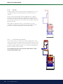
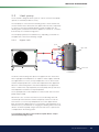
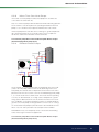
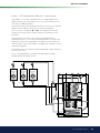
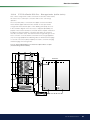
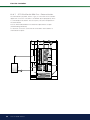
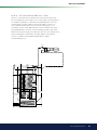
General Information For higher hot water demands, it can be more economical to set a higher temperature in the lower tank instead of exceeding the temperature limit for the heat pump in the upper tank. However, this is less beneficial to heat pump operation for the radiator requirement because of the higher operating temperature. Furthermore, where solar panels have been installed, some of the solar energy will not be exchanged in the lower tank. Additional Domestic Hot Water There is a possibility of increasing the product’s hot water capacity at certain periods, with or without the help of the immersion heater(s). You can either select extra domestic hot water immediately or schedule selection on a weekly basis. When the function is activated, the product starts producing extra hot water. The hot water is produced by the compressor working at maximum temperature, known as full condensation. In the “Installer/Settings/ Upper tank” menu you can also select the immersion heater(s) to help to produce extra hot water. Remember that the function “extra hot water” means that more energy is consumed, especially if the immersion heater(s) is/are used. See also in the “Installer/Settings/Lower tank/Timer lower tank” menu. Extra Domestic Hot Water Tank Another way of improving the hot water capacity is to install an extra hot water tank. The EcoZenith is prepared for controlling this, which provides the possibility of utilising heat pump energy to heat the extra domestic hot water tank. This means that there is a large buffer with hot water, heated by the heat pump, while the benefits in terms of operating economy using low temperature in the lower tank are maintained. Important to remember: • Avoid running hot water at the highest flow capacity. If you run a bath at a rather slower rate instead, you will get a higher temperature. • Remember that a poor mixing valve or a poor shower mixer can affect the hot water temperature. 28 CTC EcoZenith i550 Pro General Information 5. Technical data CTC EcoZenith i550 Pro 3x400V 1x230V Main dimensions on delivery mm 750x950x1700 Main dimensions when installed mm 886 x 1067 x 1700 Weight kg 256 IP class Insulation (polyurethane, PUR) IPX1 mm 90 Kvs value mixing valve 17-28kW (option mixing valve 27-45kW) m3/h 6,3 (10) Temperature thermostat overheating protector device °C 92-98 l l >600 523 Domestic hot water capacity (40°C, 22 l/min) Tank temp 55°C, HP (Heat pump 25 kW) allowed Tank temp 65/55°C, electric power 24kW allowed Pressure differential at flow 40l/min bar 0.7 Volume tank l 540 Volume domestic hot water coil l 11.4 Max operating pressure tank bar 2.5 Max operating pressure domestic hot water coil bar 9 Domestic hot water coil (finned) m 2x18,6 Domestic hot water coil circulation (finned) m 0.6 Solar coil (finned) m 10 Electrical data Power immersion heaters (option) kW Power limitation, immersion heaters 400V 3N~ 230V 1N~ 9+9 (+9) 9 3 kW/step + 0.3 kW/step 3 kW/step 4.3 inches, colour, touch Maintains the memory in the event of a power failure Not needed Realtime controlled Display Memory Back-up batteries Clock Current monitor, built-in Yes Current draw at different powers of immersion heaters 3 kW A 4.4 13 6 kW A 8.7 27 9 kW A 13.0 40 12 kW A 17.4 - 15 kW A 21.7 - 18 kW A 26.1 - 21 kW A 30.4 - 24 kW A 34.8 - 27 kW A 39.1 - CTC EcoZenith i550 Pro 29 General Information Ändr. meddel. 6. Measurements 430 230 1700 400 264 476 476 886 750 1065 950 1. 2. 3. 4. 5. 6. 7. 8. 9. Connection heating, G 1 1/4” inside Expansion vessel/Top con/Lifting socket, G 1 1/4” inside Solar coil, Ø18mm Cold water, Ø22mm Domestic hot water, Ø22mm Domestic hot water circulation, Ø22mm Radiator primary flow, spring clip 28mm Radiator return, spring clip 28mm Connection elecric (behind the front) Distr till/Antal Ytjämnhet RA Skala 1:1 Om ej annat angives gäller o Material Sign. 30 CTC EcoZenith i550 Pro Datum Ritad General Information 7. Menu overview CTC EcoZenith i550 Pro Room temp. 1 2 DHW 1 Operation Installer 2 22,2 ºC 1 Tuesday 08:45 21,2 ºC 58 ºC -5 ºC 2 Room temp. Heating circuit 1 22.3ºC (23.5)ºC Heating circuit 2 22.4ºC (23.5)ºC 1 2 Night reduction Holiday 3 Hot water Extra hot water 0.0 hours Off Temperature Normal Weekly schedule Operation 50°C 40°C 35°C Installer Time/Language Settings Software display PCB: Software HP PCB: Defined system Service 20130530 v116 20130503 CTC EcoZenith i550 Pro 31 General Information 7.1 1 Room temp. 2 1 2 Room temp. temp. Heating circuitRoom 1 22.3ºC (23.5)ºC Heating 1 22.3ºC (23.5)ºC Heating circuit 2 circuit 22.4ºC (23.5)ºC 1 Heating circuit 2 2 22.4ºC (23.5)ºC Night 1 reduction Holiday 2 Night reduction 1 3 Holiday 3 2 1 1 2 1 Night reduction heat circ. 1 Weekly program Day by day Monday - 09 18 heat - 21 circ. 1 Night06 reduction Tuesday 07 - 09 20 - 23 Weekly program by day Wednesday 06 - 09 Day 08 - 21 ThursdayMonday 06 - -- 06 -- -- 09 21 18 - 21 Friday Tuesday 06 - -- 07 -- -- 09 21 20 - 23 Saturday Wednesday 10 - 12 06 20--09 23 08 - 21 Sunday Thursday 10 - 12 06 20 -- -23 -- - 21 Friday 06 - --- - 21 Saturday 10 - 12 20 - 23 2 Sunday 10 - 12 20 - 23 1 1 2 2 Night reduction heat circ. 1 Weekly program Block Decrease 22:00 Night Sunday reduction heat circ. 1 Increase Friday 14:00 Weekly program Block Decrease -------00:00 22:00 Increase Decrease -------- Sunday 00:00 Increase Friday 14:00 Decrease -------00:00 Increase -------00:00 2 Holiday scheme Holiday schemeHoliday scheme 3 days Holiday scheme 7.2 DHW Hot water Extra hot water Weekly program DHW Hot water On 0.0 hours Extra Temperature hot water 0.0 hours NormalOn Temperature Normal Weekly schedule Weekly schedule 32 3 days CTC EcoZenith i550 Pro Weekly program Day by day Weekly program Monday 06-09 DHW 18-21 Tuesday 07-09 00-00 Weekly program Day by day Wednesday 06-09 00-00 06-09 18-21 ThursdayMonday 06-09 00-00 07-09 00-00 Friday Tuesday 06-09 00-00 06-09 00-00 Saturday Wednesday 10-12 00-00 06-09 00-00 Sunday Thursday 10-12 00-00 Friday 06-09 00-00 Saturday 10-12 00-00 Sunday 10-12 00-00 General Information 7.3 Operation Operation Stored oper data Settings for heat pump id Total operation time h: Maximum primary flow °C: Electric Heat kWh Operating time h HP 1 Operating time/24h HP1 Starts/24h HP1 50°C 40°C 35°C Operation EcoZenith Active heat sources: Heat pump, nbr of Electric heater, kW Solar Wood Ext Boiler Cooling A1 149 51 Heating circuit 1 (2) 6.0 + 0.0 Stored oper data Heating circuit Detailed oper data Primary flow 1°C Return flow °C Heating circ pump Mixing valve Primary flow 2°C Heating circ pump 2 Mixing valve 2 Room temp 3°C / Room temp cooling °C Primary flow 3°C / Primary flow cooling °C Heating circ pump 3 / Pump cooling Mixing valve 3 / Mixing valve cooling 37 (38) 20 On Open 34 (35) Off Close 32 (32) 28 (29) Off Close Detailed oper data Tank upper °C Tank lower °C DHW tank ext °C Ext. Buffer tank upper Ext. Buffer tank lower Current draw A Add heat primary flow °C Wood boiler °C Flue gas wood boiler °C Pool °C Operation data heating T ºC 60 40 20 0 60 (60) (40) 40 (43) 50 70 40 20 45 78 100 12 (35) -20 16 Out 20 Room1 0 Prim.flow1 4 Return 8 Room2 12 Prim.flow2 Operation data heat pump Status heat pump Id Product Status A1 EcoPart A2 EcoPart On, upper tank On, lower tank Select ID and OK for HP start Compressor Charge pump Brine pump Brine in/out °C Fan speed HP in/out °C Outside temp. °C Current L1 On On 78% On 4 / 1 On/48% 35/42 3 9.8 Operation data solar panels Status Outlet °C Inlet °C Pump Panel % Pump Solar Charge % Pump charge brine loop Valve charging brine loop Solar panel charge tank 68 60 46 46 Off Off CTC EcoZenith i550 Pro 33 General Information 7.4 Installer (Time/Language – Settings) Installer Time/Language Settings Defined system Service Installer Software display PCB: Software HP PCB: 20130530 v116 20130503 Time 21:34 Date 2013-06-20 Installer Time Language Installer Svenska Norsk English Deutsch Suomi Française Dansk Nederlands Settings Heating circuit 1 Heating circuit 2 Heating circuit 3 Heat pump A1 Heat pump A2 Heat pump A3 Electric heaters Upper tank Lower tank Solar panels Wood boiler External boiler External buffer Pool Remote control Communication Save settings Load settings Load factory settings Heating circuit 1 None Max primary flow °C Min primary flow °C Heating off, out °C Heating off, time Inclination °C Adjustment °C Room temp reduced °C Primary flow reduced °C Drying period 55’ Off 18 120 50 0 -2 -3 Off Heat pump A1-A3 Compressor A1 Stop at outdoor temp °C Delay between comp. Prio A/W °C Cont. brine pump on Compressor stop at brine °C Brine pump on 10 days Tariff, HP 34 CTC EcoZenith i550 Pro Permitted -15 30 7 No -5 Off Off General Information Elec. heater Solar panels Upper el.heater(s) kW Lower el.heater kW Lower el.heater °C Delay mixing valve Main fuse A Conversion factor curr. sensors Tariff, EL 9 9 50 180 60 1:1 No dT max solar °C dT min solar °C Min speed pump % Max lower tank °C Max temp brine °C dT max ground °C dT min ground °C Solar test tank min Test frequency min Winter mode Protection collector 7 3 30 85 18 60 30 4 30 Off Upper tank Stop temp HP °C Start/stop diff °C Extra DHW stop temp °C Max time upper tank Max time lower tank Min temp °C Add heat upper tank °C Periodic extra DHW, days Max temp diff end DHW °C Stop DHW diff max Run time DHW circ. Time DHW circ Diff start ext DHW buffer Timer DHW circulation 55 5 60 20 40 45 55 14 3 3 4 15 5 Wood boiler Start at flue gas temp °C Ext Boiler Timer DHW circulation Monday Tuesday Wednesday Thursday Friday Saturday Sunday 06-09 06-09 06-09 06-09 06-09 03-09 06-09 Ext boiler diff °C Minimum temp ext. boiler ° C Delay. Charge pump (min) Delay. Stop ext. boiler (min) Priority Delay priority low 00-00 00-00 00-00 00-00 00-00 00-00 00-00 dT lower ext °C dT start upper °C dT stop upper °C Charge start lower °C dT start lower °C dT stop lower °C dT setpoint lower °C HP charging 55 25 0 5 50 7 7 3 80 7 3 7 Pool Timer lower tank Weekly program Monday Tuesday Wednesday Thursday Friday Saturday Sunday 5 30 0 0 Low 120 External buffer Lower tank Tank max. °C Tank min. °C Diff. tank vs primary °C Start/stop diff tank °C Timer setpoint Timer lower tank 100 Off/Setpoint 06-07 00-00 06-07 00-00 06-07 00-00 06-07 00-00 06-07 00-00 07-08 00-00 07-08 00-00 00-00 00-00 00-00 00-00 00-00 00-00 00-00 Pool temp °C Pool diff. °C Pool prio. °C 22.0 1.0 Low CTC EcoZenith i550 Pro 35 General Information 7.5 Installer (Define system) Installer Time/Language Settings Defined system Software display PCB: Software HP PCB: Service 20130530 v116 20130503 Define System Radiator system1 Radiator system2 Radiator system 3 Heat pump DHW tank External buffer Solar Panel Electric heaters Wood boiler Ext. boiler Pool (G50, G51, B50) Cooling (B3, B13, Y3, G3) SMS Input voltage No No No No No 3x400V Define Heating circuit 2 Radiator system 2 (Y2, G2) Room sensor 2 (B12) Type Yes Yes Wireless Def. Heat pump Heat pump A1 Heat pump A2 Heat pump A3 Flow /level switch Off Off Off None Def. DHW tank DHW circulation (G40) DHW extra Buffer (B43, G41) 36 CTC EcoZenith i550 Pro No No General Information Def. Solar Panels Solar Panels (G30, B30, B31) Type Vacuum Bore hole recharge (Y31, G31) No Coil No No Define El.heaters Upper el.heater Upper opt. el.heater Lower el.heater Max power el.heaters kW Yes No Yes 18 Define Cooling Cooling Condense pipe secured Room temp. cooling No Yes 25 Define SMS Activate GSM? Level of signal Phone number 1 Phone number 2 Hardware version Software version No ------46704130901 --------------1 1 1 5 CTC EcoZenith i550 Pro 37 General Information 7.6 Installer (Service) Installer Time/Language Settings Software display PCB: Software HP PCB: Defined system Service 20130530 v116 20130503 Service Function test Alarm log Factory settings coded Quick start compressor Software update via USB Write log to USB Re-installation Calibration Sensor Function test Radiator system Heat pump Valves Electric heaters DHW circ/ Solar/ Pool External buffer Wood boiler Ext boiler Off Off Alarm log Heat pumps Latest alarm: A5 Low brine flow Time 07:20 6/3 HP(b) LP(b) 8.8 3.3 Stored alarms: A5 Wrong phase order 10:30 1/3 27.9 A5 Comm. error motor protect 09:01 1/3 27.9 Factory settings Coded Code Compressor operation Expansion valve Log compressor stop Manual register change Cooling 38 CTC EcoZenith i550 Pro 0000 SH(K) 15.9 I(A) 3.9 8.6 -227 50.0 3.6 42.2 0.0 General Information Heating circuit Mixing valve1 Rad.pump1 Mixing valve2 Rad.pump2 Mixing valve3 Rad pump3 LED room sensor Test el.heaters Closes Off Off Off Off Off Off Heat pump to test Heat pump to test Go to menu test Off Off Off Off Off Test DHW circ/ Solar/ Pool 1 Test heat pump HP Compr. HP Brine p./Fan HP Charge p Manual defrosting Compressor heater Heating condenser bowl Heating cabel 4-way valve (Y11) Upper el.heater L1 Upper el.heater L2 Upper el.heater L3 Upper opt. el.heater Lower el.heater DHW circulation pump (G40) Solar panel pump (G30) Solar heat exchanger pump (G32) Solar charge borehole (Y31/G31) Pool pumps and valve (G50/G51) On 0 0 Off Off Test external buffer Off Off 0 Off Off Off Off Off Pump to tank (G43) Pump from tank (G45) 3-way valve (Y40) Off Off Upper tank Test valves 3-way valve (Y21) Down CTC EcoZenith i550 Pro 39 General Information 8. Parameter list Heating System Factory setting User (set) value Heating buffer tank Factory setting Max primary flow °C 55 Tank max ºC 55 Min primary flow °C Off Tank min ºC 25 Heating off, out °C 18 Diff tank vs. prim. flow ºC 0 Heating off, time 120 Start/Stop diff tank °C 5 Inclination °C 50 Timer setpoint 50 Adjustment °C 0 Room temp red -2 Primary flow reduced -3 Solar panels dT max solar ºC Heat pump Delay between comp. 30 Prio A/W ºC 7 Cont. brine pump on No Compressor stop at brine °C -5 Elec. heater Electric heater(s) Factory setting User (set) value Factory setting dT min solar °C 3 Min rpm pump % 30 Max lower tank °C 85 Max brine ºC 18 dT max ground ºC 60 dT min ground ºC 30 Solar test tank min 4 Test frequency min 30 Winter mode Off 9 9 El.heater lower ºC 50 Delay mixing valve 180 Main fuse A 20 Max temp ºC 120 Conversion factor curr. sensors 1 Cooling Yes Re-cooling No Recooling to temp ºC 70 Factory setting Protection function User (set) value Factory setting Frost protect. No Anti-freeze ºC -25 Stop temp HP ºC 55 Start/stop diff ºC 5 Extra DHW stop temp °C 60 Max time upper tank 20 Max time lower tank 40 Additional heat upper tank ºC 55 Min temp ºC 45 Periodic increase DHW, days 14 Max temp diff end DHW °C 3 Ext boiler diff ºC 5 Stop DHW diff max 3 Minimum temp ext. boiler 30 Run time DHW circ. 4 Delay. charge pump (min 0 Cyclic time DHW circ. 15 Delay. Stop ext. boiler (min 0 Diff start ext DHW buffer 5 Priority Low Delay priority low 120 40 CTC EcoZenith i550 Pro User (set) value 7 El.heater lower kW Upper tank User (set) value Wood Boiler Start at flue gas °C Ext Boiler Factory setting User (set) value User (set) value 100 Factory setting User (set) value General Information External Buffer Tank Factory setting User (set) value Define external boiler Factory setting dT lower ext °C 7 Ext Boiler (04) No dT start upper°C 7 Sensor ext boiler No dT stop upper °C 3 Charge start lower °C 80 dT start lower °C 7 dT stop lower °C 3 DHW circulation (G40) No 7 External DHW tank (B43, G41) No dT setpoint lower °C HP charging Def. DHW tank Factory setting Factory setting Pool temp ºC 22.0 Pool diff ºC 1.0 Pool priority ºC Low Define system Factory setting External buffer No Wood boiler) No Ext Boiler No pool No Input voltage Def heating circuit User (set) value Off Def Solar panels Pool User (set) value User (set) value User (set) value 3x400V Factory setting Solar panels (G30, B30, B31) Define heating system 1 Room sensor 1 (B11) Only DHW Vacuum No Bore hole recharge (Y31, G31) No Define el.heaters Upper el.heater User (set) value No Type Factory setting User (set) value Yes Upper opt. el.heater No Lower el.heater Yes Max power el.heater kW 18 Def cooling User (set) value Factory setting Factory setting Cooling No Room temp. cooling ºC 25 Condense pipe secured Yes User (set) value Wire or wireless Define heating system 2 Heating circuit 2 (Y2, G2) Room sensor 2 (B12) Wire or wireless Define heating system 3 Heating circuit 3 (Y3, G3) Room sensor 3 (B13) Wire or wireless Def. heat pump Factory setting Flow/level switch None User (set) value CTC EcoZenith i550 Pro 41 General Information 9. Detail Description Menus All settings can be configured directly on screen using the straightforward control unit. The large icons operate as buttons on the touch display. Operational and temperature information is also displayed here. You can easily enter the different menus to find information on the operation or to set your own values. 9.1 CTC EcoZenith i550 Pro Room temp. DHW Tuesday 08:45 Operation Installer Start menu This menu is the system’s start menu. This provides an overview of the current operational data. The system returns to this menu if no buttons are pressed within ten minutes. All other menus can be accessed from this menu. The display switches to screensaver mode after approx. ten minutes. Touch the screen to wake it up. Room temp. Heating system settings for raising or lowering the temperature indoors and for scheduling temperature changes. 1 2 1 2 22,2 ºC 1 21,2 ºC 58 ºC -5 ºC 2 Room temp. Heating circuit 1 22.3ºC (23.5)ºC OK The OK button is used to mark and confirm Heating circuit 2 22.4ºC (23.5)ºC text and options in the menus. 1 2 DHW Settings for DHW production. Night reduction This schedules a temperatureHoliday reduction at Night reduction 3 night if selected. Operation This shows current and historical operational data for the system. Holiday This is used to reduce the room temperature Hot water permanently, e.g. during holidays when the house is unoccupied. Extra Installer This is where the installer configures the settings and service for your system. 1 hot water 0.0 hours Weekly program ThisOff is used to reduce the temperature for a fewTemperature days, for instance if you commute every Normal week. 1 Room temperature heating system 1 2 If room sensor 1 is defined, the room temperature in question is displayed here. Time/Language This is used to set the date, time and the language you want the Weekly menuschedule to be displayed in. 2 Room temperature heating system 2 If room sensor 2 is defined, the room temperature in question is displayed here. Settings Operation The settings for all heat pumps and operation of the system are usually configured by the installer. Tank temperature This shows the current water temperature in the upper tank. Outdoor temperature This displays the current outdoor temperature. Home The Home button takes you back to the Start menu. Return The Return button takes you back to the previous menu level. Define system 50°C This is used to adjust/modify the system’s structure. 40°C 35°C Service Installer settings. These are configured by the appropriate technical person. Installer Time/Language Settings Software display PCB: Software HP PCB: 42 CTC EcoZenith i550 Pro Defined system Service 20130530 v116 20130503 DHWGeneral Operation Installer Information Room temp. 1 2 1 2 22,2 ºC 9.2 Room temp. 1 21,2 ºC 58 ºC -5 ºC 2 Room temp. This is used to set the desired room temperature. The plus and minus buttons are used to set the desired temperature, displaying the so-called “setpoint” temperature in brackets. The actual value is shown in front of the brackets. Heating circuit 1 22.3ºC (23.5)ºC Heating circuit 2 22.4ºC (23.5)ºC 1 2 If heating circuit 3 or cooling is installed, the symbol for room temperature is displayed with the text “3” at the bottom right of the menu. Night reduction If you want to schedule a temperature reduction, you can continue to the Night reduction or Holiday submenus. 9.2.1 Setting without a room sensor If a room sensor has not been installed (this can be selected from the Installer/Define system/Heating circuit menu), the room temperature is adjusted by changing the house’s temperature needs to match differing outdoor temperatures. Proceed as follows: • Increase or decrease heating circuit 1 by a few steps • Wait 24 hours before making the next adjustment (if the indoor temperature is still not correct). • NOTE: The value displayed is the ratio between curve inclination and curve adjustment and has a breakpoint at an outdoor temperature of 0ºC. 9.2.2 Outdoor Sensor/Room Sensor Faults If a fault occurs with an outdoor sensor, an outdoor temperature of -5°C is simulated so that the house does not get cold, and the product emits an alarm. If a fault occurs with a room sensor, the EcoZenith automatically switches to operating according to the set curve, and the product emits an alarm. 3 Hot water Extra hot water You can select Room sensor No in the Installer/Define system/Heating system menu. This can be done for each heating system if it is difficult to find a position for the room sensor, if the floor heating system has separate room sensors, or if you use a fireplace or open stove. The alarm LED on the room sensor still functions as normal. If you use the fire or open stove only occasionally, the firing process can affect the room sensor and reduce the temperature supplied to the radiators. It can then get cold in other parts of the house. The room sensor can temporarily be deselected during the firing process. The EcoZenith then provides heating to the radiators using the set heating curve. The radiator thermostats reduce the heating supplied to the section of the house where a fire is burning. Holiday 0.0 hours Off Temperature ! Normal The thermostats of the radiators must be fully open and well operatCTC EcoZenith Tuesday 08:45 ing wheni550 thePro system is tuned. Weekly schedule Operation Room temp. 1 2 DHW 1 Operation Installer 50°C 2 22,2 ºC 21,2 ºC 58 ºC -5 ºC 40°C 1 2 35°C Room temp. Installer Heating circuit circuit 1 1 Increase/Decrease 22.3ºC (23.5)ºC Heating (50/0) Heating circuit 2 22.4ºC (23.5)ºC 1 2 Time/Language Night reduction Settings Defined system Holiday Service 3 The above menu shows heating circuit 1 without a room sensor Software display PCB: v116 (top line) and heating circuit 2 with a room sensor20130530 (bottom line). Software HP PCB: 20130503 On adjustment of heating circuit 1 (top line), the water Hot water temperature to the radiators is changed in relation to the outdoor temperature. The changes automatically take the Extra heating circuit characteristics into account. hours hot water 0.0 Off Temperature Normal Weekly schedule Operation 50°C CTC EcoZenith i550 Pro 40°C 43 Heating circuit 2 For the property owner 22.4ºC (23.5)ºC 1 2 Night reduction 1 9.2.3 Holiday 3 2 1 2 Night reduction temperature Night reduction heat circ. 1 Weekly program Monday Tuesday Wednesday Thursday Friday Saturday Sunday This menu is used to activate and set a night reduction temperature for each defined heating system. Night reduction means that you reduce the temperature indoors during scheduled periods, for example at night or when you are at work. The value by which the temperature is reduced – Room temp. reduced – can be set in the Installer/Settings/ Heater system menu. The factory set value is -2°C. Room temp. Heating circuit 1 22.3ºC (23.5)ºC ! Room temp. 22.3ºC 06 - -06 - -10 - 12 10 - 12 1 1 -- - 21 -- - 21 Extra 20 - 23 hot water 20 - 23 2 2 Holiday scheme 22:00 14:00 00:00 00:00 1 2 Weekly program DHW Day by day 06-09 18-2 07-09 00-0 Weekly program 06-09 00-0 Decrease Increase06-09 00-0 06-09 00-0 Decrease Increase10-12 00-0 10-12 00-0 Night reduc setschedule value again. Weekly 3 days 1 9.2.4 Block Sunday Friday --------------- Weekly program Monday Tuesday Day by day Wednesday Monday 06 - 09 18 - 21 Thursday Tuesday 07 - 09 20 - 23 Friday Wednesday 06 - 09 08 - 21 Saturday Thursday 06 - --- - 21 On Sunday at 10 pm, the temperature is lowered by the set Sunday Friday 06 - --- - 21 value in the Room temp. reduced menu (in the Installer/Settings Saturday 10 - 12 20 - 23 menu). On Friday at 2 pm is increased to the Sunday 10 - the 12 temperature 20 - 23 Normal Holiday scheme Weekly program Decrease 2 Increase Decrease Increase Night reduction heat circ. 1 On 2 Holiday 3 circ. 1 Night reduction heat 0.0 hours Weekly program Temperature 1 Reducing a heat pump’s temperature at night is a comfort setting (23.5)ºC which generally does not reduce energy consumption. 22.4ºC (23.5)ºC Night reduction Thursday Friday Saturday Sunday 3 days Holiday scheme 2 Day by day menu You use this menu to schedule a reduction oncircuit the days Heating 1 Night reduction Holiday 3 of the week. This schedule is repeated every week. Night reduction heat circ. 1 Block Weeklyallows program This menu you toDay setbya day reduction for a few Monday 06 - 09 18 - 21 days Tuesday during the week, for if you are working 07 -example, 09 20 - 23 Hot water Wednesday - 09 at 08 - 21 at weekends. elsewhere on weekdays06and home Weekly program Decrease Increase Decrease Increase 2 2 circuit 2 The set time is the period in which the Heating temperature is 1 normal. 2 The night reduction function is activated during 1 the rest of the time. Day by day 06 - 09 18 - 21 07 - 09 20 - 23 06 - 09 08 - 21 06 - --- - 21 06 - --- - 21 10 - 12 20 - 23 10 - 12 20 - 23 On Monday morning at 6 am the temperature is increased to normal; at 9 am it is reduced to the set night reduction temperature. At 6scheme pm the temperature is raised again until Holiday 9 pm, when the night reduction function lowers it once again. The options in the night reduction menu are Off, Day by 22.4ºC (23.5)ºC day or Block . If you select Off, no reduction is made at all. Heating circuit 2 1 1 1 Night reduc 2 Holiday Holiday scheme Holiday scheme You use this option to set the number of days that you want the set night reduction temperature to be constantly reduced. For example, if you want to go on holiday. 3 days You can apply this setting for up to 300 days. The period starts from the time for which the setting has been made. Hot water Weekly program DHW ! xtra ot water Weekly program by day The value by which the temperature is reduced Day – Room temp. reduced – Monday 06-09 18-21 0.0 canhours be set in the Installer/Settings/Heating system menu. Tuesday 07-09 00-00 The factory set n mperature value is -2°C. ormal 44 Weekly schedule CTC EcoZenith i550 Pro Wednesday Thursday Friday Hot water Saturday Sunday Extra hot water On Temperature Normal 06-09 06-09 06-09 10-12 10-12 0.0 hours 00-00 00-00 00-00 00-00 00-00 Weekly program DHW Weekly program Monday Tuesday Wednesday Thursday Friday Day by day 06-09 18-2 07-09 00-0 06-09 00-0 06-09 00-0 06-09 00-0 1 2 Night reduction heat circ. 1 For the property owner Weekly program Monday Tuesday Wednesday Thursday Friday Saturday Sunday Room temp. Heating circuit 1 Heating circuit 2 9.3 22.3ºC (23.5)ºC 22.4ºC (23.5)ºC DHW 1 Hot water We 2 Night reduction Holiday 1 1 Extra hot water 3 You use this to set the DHW comfort level you want and extra DHW. 2 Weekly program Monday Day by day 06 - 09 18 - 21 Thursday 06 - -- -- - 21 10 - 12 20 - 23 Economic – Small hot water requirement. Tuesday 07 - 09 20 - 23 (Factory-set DHW tank temperature: 50°C Wednesday 06 - 09 08 )- 21 Friday 06 - --- - 21 Normal – Normal hot water requirement. Saturday 10 - 12 20 - 23 (Factory-set DHW tank temperature: 55°C) Sunday The temperature is also determined by how the setting has been performed in the Installer/Settings/Upper tank/ Extra DHW stop temp ºC menu. 0.0 hours You can use this menu to schedule periods during weekdays Temperature when you want extra hot water. This schedule is repeated every week. The picture shows factory Normal settings that can be changed. If you want an additional period some day, e.g. in the evening, you can program recurring times. 1 2 Holiday scheme 3 days Night reduction heat circ. 1 ! Weekly program Block Decrease Sunday 22:00 Increase Friday 14:00 Decrease -------00:00 StartIncrease by setting the -------Economic 00:00 Tip: mode and if you find that you are not getting enough hot water, increase it to Normal, and so on. Hot water Extra hot water On We Weekly p Monday Tuesday Wednesd Thursday Friday Saturday Sunday 0.0hours hours 3.5 Temperature Normal Weekly schedule The example above shows that Extra DHW is On for 3.5 hours. 9.3.1 Weekly program DHW Hot water Extra hot water Holiday scheme Weekly schedule Comfort - Large DHW requirement. 1 2 (Factory-set DHW tank temperature: 60°C) Extra hot water Holiday scheme Select this option if you want to activate the Extra DHW function. When the function activated (by setting Holidayisscheme 3 daysthe number of hours) the heat pump immediately starts to produce extra DHW. You also have the option to schedule hot water production for certain times using the Weekly program function (recommended). 0.0 hours Temperature Normal Weekly p Monday Tuesday Wednesd Thursday Friday Saturday Sunday 2 On Temperature You set the values for this option apply tocirc. the heat Night which reduction heat 1 pump’s normal operation. There are three modes: On Day by day 06 - 09 18 - 21 07 - 09 20 - 23 06 - 09 08 - 21 06 - --- - 21 06 - --- - 21 10 - 12 20 - 23 10 - 12 20 - 23 Weekly program DHW Weekly program Monday Tuesday Wednesday Thursday Friday Saturday Sunday Day by day 06-09 18-21 07-09 00-00 06-09 00-00 06-09 00-00 06-09 00-00 10-12 00-00 10-12 00-00 Weekly schedule Options for the weekly program are Off or Day by day. Off No scheduled hot water production. Day by day A weekly schedule which you program yourself. This is used if you always know when you repeatedly need extra hot water, for instance in the morning and evening. On Monday morning at 6 am the system starts producing more hot water until 9 am when the temperature returns to normal again. There is a further increase between 6 pm and 9 pm. ! Tip: Set the time about one hour earlier than when you need the hot water as it may take some time to heat. CTC EcoZenith i550 Pro 45 1 1 2 1 Extra hot water 2 22,2 ºC 21,2 ºC 58 ºC1 -5 ºC2 For the property owner 2 0.0 hours Off Temperature 3 Normal 1 9.4 Operation 1 2 1 2 22,2 ºC Operation 3 2 This menu displays current and the 1 2 1 2 temperatures 2 2 heating 22,2 ºC system. 22,2 operational ºC 21,2data ºC for your 58 ºC -5 ºC21,2 3 ºC 1 1 1 Weekly schedule 2 1 2 21,2 ºC 58 ºC 40°C 2 58 ºC -5 ºC 35°C Information Press the information button to display the operational data for the relevant item. 1 1 2 50°C -5 ºC 2 1 3 2 Outside Temperature 3 Shows the outdoor temperature. 50°C Installer CTC EcoZenith i550 Pro 50°C The current temperature (50°C) in the upper tank, the current temperature (40°C) in the lower tank and the current 35 °C in the Time/Language temperature Settings Defi ned solar systemcoil (35°C) Service are shown next to this symbol. 40°C 3 Immersion heater 20130530 v116 heater´s shows immersion 20130503 operation in the upper or lower tank, respectively. Software display PCB: This symbol Software HP PCB: 40°C Indoor temperature. 35°C Shows the room temperature for room 50°C sensors 1 and 2, if these have been defined. 40°C 35°C Temperature of solar panels The current temperatures for the solar panel’s primary (89°C) and return (71°C) flow are shown next to this symbol. 50°C CTC EcoZenith i550 Pro Heat pump, EcoPart The symbol is displayed if only the CTC EcoPart heat pump(s) is/are connected to the system. 50°C Brine 40 temperature °C °C or more CTC This symbol is shown if 40 one 35°C EcoPart heat pumps are connected to 35°C the system. The current temperature (2°C) of the coolant from the collector in the heat pump and return temperature (-1°C) of the coolant back in the collector hose are shown next to this symbol. 46 Heat pump, EcoAir The symbol is displayed if only the CTC EcoAir heat pump(s) is/are connected to the system. Primary flow radiators The current primary flow temperature (42°C) supplied to the house’s radiators 50°C is shown to the left of the symbol. 40°C Return radiators The current return flow temperatures 35°C (34°C) of the radiator water is shown under the primary flow temperature. 50°C 40°C For the property owner 35°C 9.4.1 50°C Operation EcoZenith 40°C 35°C This is where the operating status and current temperatures in your heating system are displayed. Operation EcoZenith Active heat sources: Heat pump, nbr of Electric heater, kW Solar Wood Ext Boiler Cooling Heating cir 1 (2) 6.0 + 0.0 Stored oper data Heating circuit Units which are currently emitting heat. Displays the various heat sources. - White text: the unit is currently emitting/producing heat. - Greyed out text: the unit is not currently emitting/ producing heat. • Heat pump, nbr of (0...3) Displays the number of heat pumps in operation. • Electric heater, kW Displays the current electric heater power. • Solar Indicates whether solar panels are supplying heat. • Wood Indicates whether a wood boiler is supplying heat. • Add heat Indicates whether an external boiler is supplying heat • Cooling Indicates whether cooling is in fact cooling the system. Detailed oper data Stored operation data 50°C This menu shows the previous operating values for the 40°C system. 35°C Total operation time h: 14196 Shows the total time the product has been powered. Maximum primary flow °C: 51 Shows the highest temperature supplied to the radiators. Operation EcoZenith The value may indicate the temperature requirements of theActive heating The lower the value during the heatsystem/house. sources: Heat pump,the nbr more of 1 (2) it is for the heat pump’s winter period, suitable Electric heater, kW 6.0 + 0.0 Stored oper data operation. Solar Wood Ext Boiler Electric Heat kWh Cooling Heating circuit Shows the total energy consumed by the product’s electric heaters This is an indirect energy measurement, based on the operating periods of the immersion heaters. Detailed oper data Operating time h HP 1-3 Indicates the total time the heat pump compressor has been operating. Operation data heating T ºC 60 40 20 Primary flow 1°C Return flow °C Heating circ pum Mixing valve Primary flow 2°C Heating circ pum Mixing valve 2 Room temp 3°C Primary flow 3°C Heating circ pum Mixing valve 3 / Detailed op Operation data heating ! T ºC 60 40 20 0 The first figure indicates the current operational value, and the value in brackets indicates the setpoint which the heat pump is trying to achieve. Tank upper °C Tank lower °C DHW tank ext °C Ext. Buffer tank Ext. Buffer tank Current draw A Add heat primar Wood boiler °C Flue gas wood b Pool °C -20 16 Out 20 Room1 0 Prim.flow1 4 Return 8 Room2 12 Prim.flow2 Operation Status heat pump Id Product Status A1 EcoPart A2 EcoPart Compressor Charge pump Brine pump Brine in/out °C Fan speed HP in/out °C Outside temp. ° Current L1 On, upper tank On, lower tank Operation 9.4.1.1 Total operation Maximum prima Electric Heat kW Operating time Operating time/ Starts/24h HP1 Select ID andoper OK for HP start Stored data Settings for heat pump id A1 Total operation time h: 149 Maximum primary flow °C: 51 Operation data solar panels Electric Heat kWh Operating time h HP 1 Status Solar panel charge tank Operating time/24h HP1 Outlet °C HP1 68 Starts/24h Inlet °C 60 Pump Panel % 46 Pump Solar Charge % 46 Pump charge brine loop Off Valve charging brine loop Off Heating circuit Primary flow 1°C Return flow °C Heating circ pump Mixing valve Primary flow 2°C Heating circ pump 2 Mixing valve 2 Room temp 3°C / Room temp cooling °C Primary flow 3°C / Primary flow cooling °C Heating circ pump 3 / Pump cooling Mixing valve 3 / Mixing valve cooling 37 (38) 20 On Open 34 (35) Off Close 32 (32) 28 (29) Off Close Detailed oper data Tank upper °C Tank lower °C DHW tank ext °C Ext. Buffer tank upper Ext. Buffer tank lower Current draw A Add heat primary flow °C Wood boiler °C Flue gas wood boiler °C 60 (60) (40) 40 (43) 50 70 40 20 45 EcoZenith CTC 78 100 i550 Pro 47 For the property owner Operation Operating time/24h HP 1-3 Indicates the compressor’s operating time for the last 24 hours. A new value is saved/displayed once every 24 hours. After first start, 50the °C value is not shown until 24 hours have elapsed. 40°C Starts/24h HP 1-3 Shows the number of starts 35°C the compressor has performed during the last 24 hours. A new value is saved/displayed once every 24 hours. After first start, the value is not shown until 24 hours have elapsed. 9.4.1.2 Operation data Heating circuits 1-3 Operation EcoZenith Active heat sources: Heat pump, nbr of 1 (2) Electric heater, kW 6.0 + 0.0 Stored oper data Solar This Wood menu displays current temperatures and the Ext Boiler operation data for the selected circuits. Cooling Heating circuit The first figure indicates the current temperature, and the value in brackets indicates the setpoint which the Detailed oper data heat pump is trying to achieve. Primary flow 1°C 37 (38) This shows the temperature supplied to heating circuit 1 (sensor B1) and the temperature that the circuit is trying to Operation data heating achieve. This value will vary during the year according to the parameters set and the current outdoor temperature. T ºC 60 Return flow °C 20 40 This shows the temperature (sensor B7) of the water 20 that comes back from the heating circuit(s). 0 Heating circ pump 1 (On/Off) -20 Shows the operating status of the radiator pump (G1). 16 20 0 4 8 12 Out Room1 Prim.flow1 Return Room2 On, upper tank On, lower tank 2°C 37 (38) This shows the temperature supplied to heating circuit 2 (sensor B2) and the temperature that the circuit is trying to achieve. Select ID and OK for HP start Heating circ pump 2 (On/Off) Shows the operating status of the radiator pump (G2). Mixing valve 2 (Open/Close) This indicates whether thepanels mixing valve (Y2) increases Operation data solar (opens) or reduces (closes) the heat supplied to heating Status Solar panel charge tank circuit 2.°COnce the correct temperature has been Outlet 68 Inlet °C 60 reached, the mixing valve’s motor then shuts down. Pump Panel % 46 Pumptemp Solar Charge 46 Room 3°C / % Room temp cooling °C21.9 (23.0) Pump charge brine loop Off Depending on whether radiator circuit 3 or cooling is Valve charging brine loop Off activated, this indicates the room temperature for heating circuit 3/cooling (Room sensor B13). It does not indicate whether combined heating/cooling has been selected. 48 CTC EcoZenith i550 Pro Settings for heat pump id Total operation time h: Maximum primary flow °C: Electric Heat kWh Operating time h HP 1 Operating time/24h HP1 Starts/24h HP1 A1 149 51 Heating circuit Primary flow 1°C Return flow °C Heating circ pump Mixing valve Primary flow 2°C Heating circ pump 2 Mixing valve 2 Room temp 3°C / Room temp cooling °C Primary flow 3°C / Primary flow cooling °C Heating circ pump 3 / Pump cooling Mixing valve 3 / Mixing valve cooling 37 (38) 20 On Open 34 (35) Off Close 32 (32) 28 (29) Off Close Heating circuit 1 is always the hottest, and other circuits are mixedDetailed down tooper lowerdata temperatures. Tank upper °C Tank lower °C DHW tank ext °C Ext. Buffer tank upper Ext. Buffer tank lower Current draw A Add heat primary flow °C Wood boiler °C Flue gas wood boiler °C Pool °C 60 (60) (40) 40 (43) 50 70 40 20 45 78 100 12 (35) Prim.flow2 Mixing valve (Open/Close) Indicates whether the mixing valve (Y1) increases (opens) Status heat pump or reduces (closes). Once the correct temperature has Id Product Status been reached, the mixing valve’s motor then shuts down. A1 EcoPart A2 EcoPart Primary flow Stored oper data Operation data heat pump Compressor Charge pump Brine pump Brine in/out °C Fan speed HP in/out °C Outside temp. °C Current L1 On On 78% On 4 / 1 On/48% 35/42 3 9.8 For the property owner Operation Stored oper data 50°C 40°C flow cooling 32 (32) Primary flow 3°C / Primary This shows the temperature (sensor B3) supplied to 35°C heating circuit 3, or the temperature supplied to the fan convector if cooling has been activated. The value in brackets is the temperature the circuit is trying to achieve. It does not indicate whether combined heating/ cooling has been selected. Operation EcoZenith Heating circ pump 3 / Pump cooling (On/Off) Active heat sources: Heatthe pump, nbr of(G3) operating 1 (2) Shows pump’s conditions. Electric heater, kW 6.0 + 0.0 Stored oper data Solarvalve 3 / Mixing valve cooling(Open/Close) Mixing Wood Indicates whether the mixing valve (Y3) increases (opens) Ext Boiler or reduces has Cooling (closes). Once the correct temperature Heating circuit been reached, the mixing valve’s motor then shuts down. Detailed oper data 9.4.1.3 Detailed operation data Tank 60 (60)(40) T ºC upper °C The60first value shows the current temperature inside 40 the tank. Bracket 1 show the desired temperature. For 20 an air/water heat pump, the value may vary due to the 0 outdoor temperature. Bracket 2 shows the temperature -20 the desired electric heater temperature. 16 20 Room1 0 Prim.flow1 4 Return 8 Room2 A1 149 51 Heating circuit Primary flow 1°C Return flow °C Heating circ pump Mixing valve Primary flow 2°C Heating circ pump 2 Mixing valve 2 Room temp 3°C / Room temp cooling °C Primary flow 3°C / Primary flow cooling °C Heating circ pump 3 / Pump cooling Mixing valve 3 / Mixing valve cooling 37 (38) 20 On Open 34 (35) Off Close 32 (32) 28 (29) Off Close Detailed oper data Operation data heating Out Settings for heat pump id Total operation time h: Maximum primary flow °C: Electric Heat kWh Operating time h HP 1 Operating time/24h HP1 Starts/24h HP1 Tank upper °C Tank lower °C DHW tank ext °C Ext. Buffer tank upper Ext. Buffer tank lower Current draw A Add heat primary flow °C Wood boiler °C Flue gas wood boiler °C Pool °C 60 (60) (40) 40 (43) 50 70 40 20 45 78 100 12 (35) 12 Prim.flow2 Tank lower °C 40 (43) Indicates the current temperature in the lower tank, plus Status heat pump the temperature the system is trying to achieve. Id Product Status A1 EcoPart External DHW tank A2 EcoPart On, upper tank °C 50 On, lower tank Indicates the current temperature in the external DHW tank, plus the temperature the system is trying to achieve. Select ID and OK for HP start Ext. buffer tank upper 70 Displays the current temperature in the upper part of the buffer tank. Operation data heat pump Compressor Charge pump Brine pump Brine in/out °C Fan speed HP in/out °C Outside temp. °C Current L1 On On 78% On 4 / 1 On/48% 35/42 3 9.8 Operation solar panels Ext. buffer tankdata upper 40 Displays the current temperature in the lower part of the Status Solar panel charge tank Outlet °C 68 buffer tank. Inlet °C Pump Panel % Current draw A Pump Solar Charge % Pump charge brine loop Indicates the value of current Valve charging brine loop 60 46 46 Off amps Off 20 in for the phase with the greatest load (the house phase). Add heat primary flow °C Indicates the current temperature supplied by the external boiler. 45 Wood boiler °C 78 Indicates the current temperature supplied by the wood boiler. CTC EcoZenith i550 Pro 49 Operating time/ Starts/24h HP1 35°C For the property owner Operation EcoZenith Flue gas wood boiler °C 100 Displays current flue gas temperature in the connected wood boiler. Pool °C 24 (28) Indicates the current temperature in the pool, plus the temperature the system is trying to achieve. Active heat sources: Heat pump, nbr of Electric heater, kW Solar Wood Ext Boiler Cooling Heating cir 1 (2) 6.0 + 0.0 Stored oper data Heating circuit Detailed oper data Primary flow 1°C Return flow °C Heating circ pum Mixing valve Primary flow 2°C Heating circ pum Mixing valve 2 Room temp 3°C Primary flow 3°C Heating circ pum Mixing valve 3 / Detailed op 9.4.2 Operation data heating system Tank upper °C Tank lower °C DHW tank ext °C Ext. Buffer tank Ext. Buffer tank Current draw A Add heat primar Wood boiler °C Flue gas wood b Pool °C Operation data heating T ºC 60 50°C This shows operation data for heating systems 1 and 2 for 40the °C last 24 hours. The furthest point to the right is the present, while the data for the last 24 hours is displayed to 35the °Cleft. The time “rolls” forward. The blue curve is the current outdoor temperature. The green and pink curves are room temperatures 1 and 2, respectively. 40 20 0 -20 16 Out 20 Room1 0 Prim.flow1 4 Return 8 Room2 12 Prim.flow2 Operation Status heat pump Id Product Status A1 EcoPart A2 EcoPart On, upper tank On, lower tank The red and grey curves are primary flow temperatures 1 and 2, respectively. The yellow curve is the radiator circuit’s/circuits’ return temperature. Select ID and OK for HP start Operation data solar panels Status Outlet °C Inlet °C Pump Panel % Pump Solar Charge % Pump charge brine loop Valve charging brine loop 50 CTC EcoZenith i550 Pro Solar panel charge tank 68 60 46 46 Off Off Compressor Charge pump Brine pump Brine in/out °C Fan speed HP in/out °C Outside temp. ° Current L1 T ºC 60 40 For the property owner 20 0 Ext. Buffer tank Current draw A Add heat primar Wood boiler °C Flue gas wood b Pool °C -20 16 Out 9.4.2.1 Heat pump status 20 Room1 0 Prim.flow1 Blocked in menu The heat pump’s compressor is not permitted in the Installer/Settings/Heat pump menu. Communication error HP The EcoZenith cannot communicate with the heat pump. On, upper tank The heat pump is heating the upper tank. 8 Room2 12 Prim.flow2 Operation Status heat pump Id Product Status A1 EcoPart A2 EcoPart This menu shows the current status of defined heat pumps. Heat pumps A1-A3 (EcoAir or EcoPart) can have the following statuses: 4 Return On, upper tank On, lower tank Select ID and OK for HP start Compressor Charge pump Brine pump Brine in/out °C Fan speed HP in/out °C Outside temp. ° Current L1 The illustration above shows an example of the status for two defined heat pumps. Operation data solar panels Status Outlet °C Inlet °C Pump Panel % Pump Solar Charge % Pump charge brine loop Valve charging brine loop Solar panel charge tank 68 60 46 46 Off Off Off, start delay The heat pump’s compressor is not running and is prevented from starting due to the start delay. Off, ready to start The heat pump’s compressor is not running and is ready to start. Flow on The heat pump and fan are started before the compressor. Shown for EcoAir heat pumps. On, lower tank The heat pump is supplying heat. Defrosting The heat pump defrosts. Shown for EcoAir heat pumps. Blocked The heat pump has stopped due to a temperature or pressure that has reached its maximum value. Off, alarm The heat pump is off and is emitting an alarm signal. Function test The compressor is function tested. CTC EcoZenith i550 Pro 51 T ºC 60 Ext. Buffer tank lower Current draw A Add heat primary flow °C Wood boiler °C Flue gas wood boiler °C Pool °C 40 For the property owner 20 0 40 20 45 78 100 12 (35) -20 16 Out 20 Room1 0 Prim.flow1 4 Return 8 Room2 12 Prim.flow2 9.4.2.2 Operation data heat pump Status heat pump Id Product Status This menu is intended for servicing and advanced A1 EcoPart On, upper tank troubleshooting, and displays information A2 EcoPart On, lower about tank the heat pump that has been selected from the previous menu (“Heat pump status”). Compressor On (On/Off) Select ID and OK for HP start Shows whether the compressor is operating or not. Charge pump On/78% (On/Off/0 to 100) Shows the charge pump’s operational status and flow Operation data solar panels as a percentage. Status Solar panel charge tank Outletpump °C 68 Brine On (On/Off) Inlet °C 60 Indicates whether the brine pump46 is on or off. Shown for Pump Panel % Pump Solar % 46 EcoPart heatCharge pumps. Pump charge brine loop Valve charging brine loop Off Off Brine in/out °C 4/1 (-99...99) This shows the brine pump’s incoming and outgoing temperatures. Shown for EcoPart heat pumps. Fan speed On/48% (On/Off/0 to 100) This shows the heat pump’s operational status and the fan speed as a percentage. Shown for EcoAir heat pumps. HP in/out °C 35/42 (0 to 99/0 to 99) This shows the heat pump’s return and primary flow temperatures. Outside Temp °C 3 (-50...50) Shows the outside temperature (sensor B15). Shown for EcoAir heat pumps. Current L1 9.8 (0.0 to 50.0) Show the current for phase L1 to the compressor. Phases 2 and 3 are not measured in the product. 52 CTC EcoZenith i550 Pro Operation data heat pump Compressor Charge pump Brine pump Brine in/out °C Fan speed HP in/out °C Outside temp. °C Current L1 On On 78% On 4 / 1 On/48% 35/42 3 9.8 A1 EcoPart A2 EcoPart On, upper tank On, lower tank For the property owner Select ID and OK for HP start 9.4.3 Operation data solar panels This menu shows information about solar panels (if 50°C defined in the Installer/Define system/Solar panels menu). 40°C Charge pump Brine pump Brine in/out °C Fan speed HP in/out °C Outside temp. ° Current L1 Operation data solar panels Status Outlet °C Inlet °C Pump Panel % Pump Solar Charge % Pump charge brine loop Valve charging brine loop Solar panel charge tank 68 60 46 46 Off Off Status Solar panel charge tank 35panels: °C Shows status for solar • Off Solar panels are in operating mode Off. • Solar panel charge tank The solar panels are charging the Ecozenith’s tank • Solar panel update. Vacuum The solar panels are charging the hot water system. • Solar panel charge ground source The solar panels are charging the ground source. From solar panels °C 68 (-99...99) This shows the temperature of the flow supplied from the solar panels (sensor B31). To solar panels °C 60 (-99...99) This shows the temperature of the flow supplied to the solar panels (sensors B30). Pump Panel % 46 (0...100) This shows the current charge as a percentage of maximum capacity for the pump (G30). Pump Solar Charge % 46 (0...100) This shows the current charge as a percentage of maximum capacity for the pump (G32). Only displayed if the solar panel is connected via a heat exchanger to the EcoZenith. Pump charge brine loop (On /Off) This shows the operating mode for the pump (G31) for recharging the bedrock. Valve charging Brine loop (On /Off) This shows the mode for the valve (Y31) for recharging the bedrock. CTC EcoZenith i550 Pro 53 For the property owner 9.5 Installer Installer This menu includes four submenus: Time/Language, Settings, Defined system, and Service. Time/Language Settings Defined system Service Installer I Software display PCB: Software HP PCB: Installer Time/Language 9.5.1 Settings Defined system Time/Language Software display PCB: Time/Language Settings Software HP PCB: 20130530 v116 20130503 Date Service 20130530 Defined system v116 Service 20130503 This is used to set the time, date and language. The clock display saves PCB: the settings in20130530 the eventv116 of a power cut. Software Software HP PCB: 20130503 Summer/winter time is changed automatically. Installer Time and date settings Time Installer Installer Time 21:34 Date 2013-06-20 Installer Time Time 21:34 Language Date 2013-06-20 I ClickInstaller on the time symbol. Press “OK” to highlight the first value and use the arrows to set theTime correct value.Language Sve InstallerSettings Time Setting the language Language Click on the language symbol. Select the language you want by clicking on the screen. The language Settings selected is highlighted by a green ring. Heating circuit 1 Heating circuit 2 Heating circuit 3 Heat Settings pump A1 Heat pump A2 Heating circuit 1 Heat pump A3 Heating circuit 2 Electric heaters Heating circuit 3 Upper tank Heat pump A1 Lower tank Heat pump A2 Solar panels Heat pump A3 Wood boiler Electric heaters External boiler Upper tank External buffer Lower tank Pool Solar panels Remote control Wood boiler Communication External boiler Save settings External buffer Load settings Pool Load factory settings Remote control Communication Save settings Load settings Load factory settings None None Heating circuit 1 Heating circuit 2 Heating circuit 3 Installer Heat pump A1 Heat pump A2 Svenska Norsk Heat pump A3 Electric heaters Upper tank Lower tank Svenska Norsk SuomiSolar panels Française Wood boiler External boiler External buffer Pool Suomi Française Remote control Heating circuit 1 Communication Save settings Max primary flow °C Load settings Min primary flow °C Load factory settings Heating off, out °C Heating circuit 1 Heating off, time Inclination °C Max primary flow °C Adjustment °C Min primary flow °C Room temp reduced °C Heating off, out °C Primary flow reduced °C Heating off, time Drying period Inclination °C Adjustment °C Room temp reduced °C Primary flow reduced °C Drying period Su English Deutsch English Dansk Deutsch Nederlands Dansk Nederlands None 55’ Off 18 120 50 55’ 0 Off -2 18 -3 120 Off 50 0 -2 -3 Off Heat pump A1-A3 54 CTC EcoZenith i550 Pro Compressor A1 Stop at outdoor temp °C Delay between comp. Heat°Cpump A1-A3 Prio A/W Cont. brine pump on Compressor A1 Compressor stop at brine °C Stop at outdoor temp °C Brine pump on 10 days Delay between comp. Tariff, HP Prio A/W °C Cont. brine pump on Compressor stop at brine °C Brine pump on 10 days Tariff, HP Permitted -15 30 7 No Permitted -5 -15 Off 30 Off 7 No -5 Off Off Max Min p Heat Heat Inclin Adju Room Prim Dryin Com Stop Dela Prio Cont Com Brine Tariff Time/Language Settings Defined system Service Installer Software display PCB: Software HP PCB: 20130530 v116 20130503 Time 21:34 Date 2013-06-20 9.5.2 Settings Installer Installe Svenska Settings This is used to set the parameters for your home’s heating requirements. It is important that this basic Language setting is right forTime your home. Values which are set incorrectly may mean that your property is not warm enough or that an unnecessarily large amount of energy is being used to heat your property. Heating circuit 1 Heating circuit 2 Heating circuit 3 Heat pump A1 Heat pump A2 Heat pump A3 Electric heaters Installer Upper tank Lower tank Solar panels Wood boiler External boiler External buffer Svenska Norsk Pool Remote control Communication Save settings Load settings Française Suomi Load factory settings Settings Heating circuit 1 Heating circuit 2 Heating circuit 3 Heat pump A1 Heat pump A2 Heat pump A3 Electric heaters 9.5.2.1 Heating circuits 1-3 Upper tank Lowerprimary tank Max. flow °C 55 (30 to Solar panels Maximum permitted temperature supplied to the Wood boiler External boiler respective heating system. External buffer Pool Min. primary flow °C Off (Off/15 to Remote control None Minimum permitted temperature supplied to the Communication Save settings respective heating system. Load settings Load factory settings Time the property Language For owner 80) 65) Heating off, outside °C 18 (10 to 30) Outside temperature limit (B15) at which the house no longer requires heating. The radiator pump stops, and the mixing valve remains closed. The radiator pump is activated daily for a short period to prevent it from jamming. The system restarts automatically when heating is required. Heating off, time 120 (30 to 240) When the outside temperature (sensor B15) falls to the limit at which heating is required again, “Heating off, out °C” must remain this low or lower for this many minutes before heating the house is permitted again. Inclination 50 (25 to 85) Inclination means the temperature your property needs at different outdoor temperatures. See more detailed information in the “Your home’s heating installation” chapter. The value set is the outgoing flow temperature to radiators when the outdoor temperature is -15 °C. Suomi Heating English Max primary Min primary Heating off, Heating off, Inclination °C Adjustment ° Room temp Primary flow Drying perio Deutsch None Dansk Nederlands Heating circuit 1 Max primary flow °C Min primary flow °C Heating off, out °C Heating off, time Inclination °C Adjustment °C Room temp reduced °C Primary flow reduced °C Drying period ! Heat pu 55’ Off 18 120 50 0 -2 -3 Off Compressor Stop at outd Delay betwe Prio A/W °C Cont. brine p Compressor Brine pump Tariff, HP Heat pump A1-A3 Tip: Find out more about these set- Compressor A1 Permitted tings intemp the°C“Your home’s heating Stop at outdoor -15 chapter. Delaysettings” between comp. 30 Prio A/W °C 7 Cont. brine pump on No Compressor stop at brine °C -5 Brine pump on 10 days Off Tariff, HP Off For example: “Inclination 50” means that the temperature of the water supplied to the radiators will be 50°C when the outdoor temperature is -15°C, if the adjustment is set to 0. If the adjustment is set to +5, the temperature will be 55°C instead. The curve is increased by 5°C at all outdoor temperatures, i.e. the curve is parallel offset by 5°C. Curve adjustment 0 (-20 to 20) The adjustment means that the temperature level can be raised or lowered at a specific outdoor temperature. CTC EcoZenith i550 Pro 55 For the property owner Room temp. reduced °C -2 (0 to -30) The menu is displayed if room sensors for the respective heating circuit are installed. You define here by how many degrees the room temperature is to be reduced during the various scheduled reduction periods, e.g. Night reduction, Holiday etc. Primary flow reduced °C -3 (0 to -30) The menu is displayed if room sensors for the respective heating circuit are not installed. This is used to set the number of degrees by which the primary flow temperature for the respective heating system will be reduced during the various scheduled reduction periods. Drying period Off (Off/Type1/Type2). Is activated to limit the flow temperature in connection with construction/installation. The setting automatically passes to “Off” after completed cycle. Type 1 Constant primary flow temperature of 25 °C during the first day and the subsequent three days. During the next four days the primary flow temperature is set according to the “Max Primary Flow” menu. However, it cannot be higher than 55 °C. Type 2 25 °C primary flow temperature during the first day. The temperature is raised by 5 degrees per day until the set temperature in the “Max primary flow” menu is obtained. During the next 10 days the flow temperature is constant according to the “Max primary flow” menu. Thereafter the primary flow is reduced by 5 degrees per day again until the temperature is down to 25 °C. 56 CTC EcoZenith i550 Pro Example: As a general rule, a Primary flow reduced value of 3 to 4°C is equivalent to a reduction of approximately 1°C in room temperature in a normal system. External boiler External buffer Pool Remote control Communication Save settings Load settings Load factory settings None 9.5.2.2 Heat pump A1-A3 In the “Heat pump” menu you make settings for the heat pumps which have been defined. Compressor A1 Blocked (Blocked /Permitted) The heat pump is supplied with a blocked compressor. Permitted means that the compressor is allowed to operate. Heating off, time Inclination °C Adjustment °C For °C the Room temp reduced Primary flow reduced °C Drying period 120 50 0 property -2 -3 Off owner Heat pump A1-A3 Compressor A1 Stop at outdoor temp °C Delay between comp. Prio A/W °C Cont. brine pump on Compressor stop at brine °C Brine pump on 10 days Tariff, HP Permitted -15 30 7 No -5 Off Off Stop at outdoor temp °C -15 (-22...10) This menu appears if the heat pump is a CTC EcoAir. At this temperature the compressor is no longer permitted to operate. The heat pump re-starts 2 ° C warmer than the set value. The lowest outdoor re-start temperature is -18 ° C. Delay between HP 30 (5 to 180) This is used to set the delay time before the second heat pump in the system is allowed to start, when the first heat pump is already operating. This value is also valid for the amount of time that will pass before the third heat pump is allowed to start, when the first and second heat pumps are operating, and so on. NOTE: Only indicated for heat pump A1. Prio. EcoAir/EcoPart °C 7 (-20 to 15) This temperature setting controls the prioritisation between the EcoAir air/water heat pump and the EcoPart liquid/water heat pump, if both of these are connected to the EcoZenith. The factory value is 7°C; this means that the EcoAir is prioritised for outside temperatures from 7°C and warmer. NOTE: Only indicated for heat pump A1. Cont. brine pump on No (No/Yes) Setting for whether the brine pump is permitted to run all the time or permitted to start and stop. Applies to EcoPart heat pumps only. Compressor stop at brine °C -5 (-7 to -5) This menu defines the brine temperature at which the compressor will be stopped. Applies to EcoPart heat pumps only. Brine pump on 10 days Off (Off/On) After installation is complete, you can choose to run the brine pump constantly for 10 days to remove air from the system. Applies to EcoPart heat pumps only. Tariff HP Off (Off/On) This is used when a dual tariff is used with lower energy costs at set hours of the day. The heat pump can then take advantage of reduced primary energy costs. It must be set to Off. NOTE: Only indicated for heat pump A1. CTC EcoZenith i550 Pro 57 For the property owner 9.5.2.3 Elec. heater In the “Elec. heater” menu you can make settings affecting the operation of the immersion heaters. El.heater upper kW 9 (0,3...18 Here you select the power that the upper immersion heaters are allowed to emit. Elec. heater Sol Upper el.heater(s) kW Lower el.heater kW Lower el.heater °C Delay mixing valve Main fuse A Conversion factor curr. sensors Tariff, EL 9 9 50 180 60 1:1 No dT max s dT min s Min spee Max low Max tem dT max g dT min g Solar tes Test freq Winter m Protectio El.heater lower kW 9 (0,3...9) Here you select the power that the upper immersion heaters are allowed to emit El.heater lower °C 50(30...60) Setting of temperature for the lower immersion heater. The lower immersion heater is only allowed to operate when the heat pump is blocked for some reason. Delay mixing valve 180(30...240) This is where the mixing valve delay is set - the period before it draws energy from the upper part of the tank. The mixing valve can be blocked so that it never retrieves energy from the upper part of the tank. Main fuse A 20 (16...100) The property’s main fuse size is set here. This setting and the fitted current sensors ensure the fuses are protected when using appliances which generate temporary power peaks, for example, cookers, ovens, engine heaters etc. The product temporarily reduces power drawn where this type of equipment is being used. Conversion factor curr. sensors 1:1 (1...10) This menu contains the factor the current sensor are to use. This setting is only performed if the connection has been installed for a current sensor for higher currents. Example: User (set) value 2 => 16 A will be 32 A. Tariff El Off (Off/On) This indicates whether the product is connected to tariffcontrolled electricity. Upper tank Stop temp HP °C Start/stop diff °C Extra DHW stop temp °C Max time upper tank Max time lower tank Min temp °C Add heat upper tank °C Periodic extra DHW, days Max temp diff end DHW °C Stop DHW diff max Run time DHW circ. Time DHW circ Diff start ext DHW buffer Timer DHW circulation 55 5 60 20 40 45 55 14 3 3 4 15 5 Wo Start at fl Ext Timer DHW circulation Monday Tuesday Wednesday Thursday Friday Saturday Sunday 06-09 06-09 06-09 06-09 06-09 03-09 06-09 Ext boile Minimum Delay. C Delay. St Priority Delay pr 00-00 00-00 00-00 00-00 00-00 00-00 00-00 Ext Lower tank Tank max. °C Tank min. °C Diff. tank vs primary °C Start/stop diff tank °C Timer setpoint Timer lower tank dT lower dT start dT stop Charge s dT start dT stop dT setpo HP charg 55 25 0 5 50 Poo Timer lower tank Weekly program Monday Tuesday Wednesday Thursday Friday Saturday Sunday 58 CTC EcoZenith i550 Pro Off/Setpoint 06-07 00-00 06-07 00-00 06-07 00-00 06-07 00-00 06-07 00-00 07-08 00-00 07-08 00-00 00-00 00-00 00-00 00-00 00-00 00-00 00-00 Pool tem Pool diff Pool prio Lower el.heater kW Lower el.heater °C Delay mixing valve Main fuse A For the Conversion factor curr. sensors Tariff, EL 9 50 180 60 property 1:1 No dT min s Min spee Max low Max tem dT max g dT min g Solar tes Test freq Winter m Protectio owner 9.5.2.4 Upper tank In the “Upper Tank” menu you make settings which affect the operation of the upper part of the tank. Stop temp. HP °C 55 (20 to 60) At the selected temperature, the heat pump stops charging the upper tank. Start/stop diff °C 5 (1 to 7) Hysteresis before the heat pump starts or stops charging the upper tank. Extra DHW stop temp. °C 60 (20 to 62) This menu is used to specify the setpoint for the heat pump to charge hot water. Max time upper tank 20 (5...60) This is the maximum time spent by the heat pump charging the upper tank if it is needed in the lower tank. Max time lower tank 40 (10...120) This is the maximum time spent by the heat pump charging the lower tank if it is needed in the upper tank. Upper tank Stop temp HP °C Start/stop diff °C Extra DHW stop temp °C Max time upper tank Max time lower tank Min temp °C Add heat upper tank °C Periodic extra DHW, days Max temp diff end DHW °C Stop DHW diff max Run time DHW circ. Time DHW circ Diff start ext DHW buffer Timer DHW circulation 55 5 60 20 40 45 55 14 3 3 4 15 5 Wo Start at fl Ext Timer DHW circulation Monday Tuesday Wednesday Thursday Friday Saturday Sunday 06-09 06-09 06-09 06-09 06-09 03-09 06-09 Ext boile Minimum Delay. C Delay. St Priority Delay pr 00-00 00-00 00-00 00-00 00-00 00-00 00-00 Min. temp. °C 45 (35 to 55) This menu is used to specify the lowest permitted temperature in the upper tank. Add heat upper tank °C 55 (45...80) Stop temperature for additional heat from immersion heater/external boiler. Used when the EcoZenith is in additional heating status, when no heat from the heat pump is available. Ext Lower tank Tank max. °C Tank min. °C Diff. tank vs primary °C Start/stop diff tank °C Timer setpoint Timer lower tank dT lower dT start dT stop Charge s dT start dT stop dT setpo HP charg 55 25 0 5 50 Periodic extra DHW, days 14 (0 to 30) The menu defines the interval for the periodic increase of the hot water tank (at 65°C to protect against legionella). Max. temp. diff. interrupted DHW °C 3 (2 to 7) If there is a heating requirement, hot water charging is interrupted earlier than the time at which the maximum temperature has been reached, in order to avoid the compressor stopping while hot water is swapped for heating. Stop DHW diff. max. 3 (2 to 10) Hot water charging is normally interrupted in the hot water sensor, but this can also occur in the condensation temperature which is calculated based on the heat pump’s internal pressure sensor. The condensation temperature is significantly increased during hot water charging. This menu relates to the value from the maximum permitted condensation temperature that interrupts hot water charging. If there is a heating requirement, the system then diverts to charging the heating system. Poo Timer lower tank Weekly program Monday Tuesday Wednesday Thursday Friday Saturday Sunday Off/Setpoint 06-07 00-00 06-07 00-00 06-07 00-00 06-07 00-00 06-07 00-00 07-08 00-00 07-08 00-00 Pool tem Pool diff Pool prio 00-00 00-00 00-00 00-00 00-00 00-00 00-00 CTC EcoZenith i550 Pro 59 For the property owner Main fuse A Conversion factor curr. sensors Tariff, EL Winter m Max tem Protectio dT max g 60 1:1 No dT min g Solar tes Test freq Winter m Protectio Wo Upper tank Run time DHW circ. 4 (1 to 90) The operating time the domestic hot water circulation should take place during each period. Applies if DHW circulation has been defined in the Installer/Defined system/DHW tank menu. Cyclic time DHW circ. 15 (5 to 90) The cyclic time for domestic hot water circulation. DHW circulation must have been defined in the Installer/ Defined system/DHW tank menu. Diff start ext DHW buffer 5 (3...15) This menu is used to select the temperature difference at which the charging of the external DHW tank is required to start. The difference is specified against the setpoint that is set in the Stop temp. HP °C menu. Timer DHW circulation This menu displays the scheduled weekday periods when the DHW circulation pump is to run. This schedule is repeated every week. 9.5.2.5 Lower tank In the “lower tank” menu you make settings which affect the operation of the lower part of the tank. Tank max. °C 55 (20 to 70) This menu is used to set the highest temperature required for the lower tank. Tank min. °C 25 (20 to 60) This menu is used to set the lowest temperature required for the lower tank. Diff. tank and prim. flow °C 0 (0 to 15) This menu is used to set the difference between the temperature in the tank and the outgoing primary flow temperature to the heating system, if required. Start/Stop diff. tank °C 5 (3 to 10) The hysteresis between the heat pump’s start and stop conditions in charging the lower tank. Timer setpoint 50 (20 to 60) This menu is used to specify the setpoint that is active during the period of time set by the timer. Timer lower tank See the chapter “Timer lower tank” below. 9.5.2.6 Timer lower tank This menu is used to schedule the weekday periods you require the lower tank to be heated. This schedule is repeated every week. The illustration shows factory settings, which can be modified. 60 CTC EcoZenith i550 Pro Stop temp HP °C Start/stop diff °C Extra DHW stop temp °C Max time upper tank Upper tank Max time tank Elec.lower heater Min temp °C Stop temp HP °C kW Upper el.heater(s) Add heat upper tank °C Start/stop diff °CkW Lower el.heater Periodic extra DHW, Extra DHW stop tempdays °C Lower el.heater °C Max time temp diff end DHW °C Max upper tank Delay mixing valve Stop time DHWlower diff max Max tank Main fuseDHW A Run time circ. Min temp °C Conversion factor curr. sensors Time DHWupper circ Add heat tank °C Tariff, EL ext DHW Diff start buffer Periodic extra DHW, days Timertemp DHWdiff circulation Max end DHW °C Stop DHW diff max Run time DHW circ. DHW circulation Time Timer DHW circ Diff start ext DHW buffer Timer DHW circulation06-09 00-00 Monday 55 5 60 20 40 45 55 9 55 5 9 14 60 50 3 20 180 3 40 60 4 45 1:1 15 55 No 5 14 Start at fl Sol Wos dT max dT min s Start at fl Min spee Max low Max tem dT max g dT min g Solar tes Test freq Winter m Protectio Ext 3 3 4 15 5 Upper tank Tuesday 06-09 00-00 Wednesday 06-09 00-00 55 Stop temp HP °C Timerdiff DHW Thursday 06-09 00-00 5 Start/stop °C circulation Friday 00-00 60 Extra DHW stop temp06-09 °C Saturday 03-09 00-00 00-00 20 Max time upper tank 06-09 Monday Sunday Max time lower tank 06-09 Tuesday 06-09 00-00 00-00 40 Min temp °C Wednesday 06-09 00-00 45 Add heat upper tank °C Thursday 06-09 00-00 55 Periodic Friday extra DHW, days 06-09 00-00 14 Max temp diff end DHW °C 00-00 3 Saturday 03-09 The circulation pump for hot water is set in the above menu to Stop DHW diff max 06-09 00-00 3 Sunday runRun on time Mondays between 6 am and 94am and between 9 pm DHW circ. and 11Lower pm. circ tank Time DHW 15 Diff 5 Tankstart max.ext °CDHW buffer 55 Timer DHW Tank min. °Ccirculation 25 Diff. tank vs primary °C Start/stop diff tank °C tank circulation Timer DHW TimerLower setpoint Timer lower tank Tank max. °C Monday 06-09 Tank min. °C Tuesday 06-09 Diff. tank vs primary °C Wednesday Start/stop diff tank °C06-09 Thursday 06-09 Timer setpoint Friday 06-09 Timer lower tank Saturday 03-09 Sunday 06-09 00-00 00-00 00-00 00-00 00-00 00-00 00-00 0 5 50 55 25 0 5 50 Off/Setpoint 06-07 00-00 06-07 00-00 06-07 00-00 06-07 00-00 06-07 00-00 Off/Setpoint 55 07-08 06-07 00-00 00-00 25 07-08 06-07 00-00 00-00 0 06-07 00-00 5 06-07 00-00 50 06-07 00-00 07-08 00-00 07-08 00-00 00-00 00-00 00-00 00-00 00-00 00-00 00-00 00-00 00-00 00-00 00-00 00-00 00-00 00-00 Ext dT lower dT start dT stop u Charge s Ext dT start dT stop l dT lower Ext boile dT start setpo dT Minimum HP chargu dT stop Delay. Ch ChargeSts Delay. dT start Priority dT stop Delay prl dT setpo HP charg Pool tem Pool diff Pool prio Poo Ext dT lower Pool tem dT start Pool diff dT stop Pool priou Charge s dT start dT stop l dT setpo HP charg Poo Timer lower tank Weekly program Monday Tuesday Wednesday Thursday Friday Saturday Sunday Minimum Delay. Ch Delay. St Priority Delay pr Poo Timer lower tank Weekly program Monday Tuesday Wednesday Timer Thursday Lower lower tank tank Friday Weekly program Tank max. °C Saturday Monday Tank min. °C Sunday Tuesday Diff. tank vs primary °C Wednesday Start/stop diff tank °C Thursday Timer setpoint Friday Timer lower tank Saturday Sunday Ext boile Minimum Delay. Ch Delay. St Wo Ext Priority Delay prfl Ext boile Start at Off/Setpoint 06-07 00-00 06-07 00-00 06-07 00-00 06-07 00-00 06-07 00-00 07-08 00-00 07-08 00-00 00-00 00-00 00-00 00-00 00-00 00-00 00-00 Pool tem Pool diff Pool prio For the property owner 9.5.2.7 Solar panels Elec. heater dT max. solar °C 7 (3 to 30) Upper el.heater(s) kW 9 Here you can difference determining Lower el.heater kW set the temperature 9 Lower el.heater °C 50 is started. when charging of solar energy Delay mixing valve 180 Main fuse defined A Type as “Coil”. When60the solar panel is this many Conversion factor curr. sensors 1:1 degrees warmer than the solar coil in the EcoZenith, the Tariff, EL No solar panels’ circulation pump (G30) starts. Type defined as “Heat exchanger”. When the solar panel is this many degrees warmer than the lower tank in the EcoZenith, the solar panels’ circulation pumps (G30) start. Upper tank charged primarily in the lower tank. If StopSolar temp is HPalways °C 55 Start/stop diff °C 5 enough solar energy and temperature are present, they Extra DHW stop temp °C 60 are transferred to the upper tank via the heat distribution Max time upper tank 20 Maxpipes. time lower tank 40 Min temp °C 45 AdddT heat upper tank °C 55 min. solar °C 3 (2 to 20) Periodic extra DHW, days 14 When the temperature difference above falls to this set Max temp diff end DHW °C 3 themax circulating pump (G30) for the solar panels Stopvalue, DHW diff 3 Run time DHW circ. 4 stops and the solar energy charge to the lower tank is Time DHW circ 15 Diff terminated. start ext DHW buffer 5 Timer DHW circulation Min. speed pump % 30 (30 to 100) Here you set the minimum permissible rpm, in Timer DHW circulation percentage, for the solar panels’ circulating pump. Monday 06-09 Max lower tank °C 00-00 85 (10...95) Tuesday 06-09 00-00 The maximum 06-09 permitted temperature in the lower Wednesday 00-00 Thursday 00-00 tank ceases once the set tank. Charging06-09 of the lower Friday 06-09 00-00 temperature has been reached. Saturday 03-09 00-00 Sunday 06-09 00-00 Max. brine °C 18 (1 to 30) Setting for maximum permitted brine temperature. This menu shows if the function “recharge the bore hole” has been selected in the “Def Solar Energy” menu. Solar charging of the bore hole ceases when this value has Lower tank been reached. Tank max. °C 55 Tank min. °C 25 dT max. bedrock °C 60 (3 to 120) Diff. tank vs primary °C 0 Setting start Start/stop difffor tank °C conditions for 5 solar charging of bedrock. Timer setpoint 50 Specifies the temperature difference (solar panels– Timer lower tank bedrock) at which charging begins. dT min. bedrock °C 30 (1 to 118) Setting for stop conditions for solar charging of bedrock. Specifies the temperature difference (solar panels– bedrock) at which charging stops. Timer lower tank Solar test tank min. 4 (1 to 20) Weekly program Off/Setpoint (Only if vacuum solar panels is defined) When recharging 06-07 00-00 00-00 Monday 06-07 00-00charging 00-00 is performed the bedrock, switching to tank Tuesday 06-07 00-00 00-00 Wednesday once every 30 minutes to check whether tank charging 06-07 00-00 00-00 Thursday is possible (factory setting). The test is carried out at the 06-07 00-00 00-00 Friday 07-08 00-00 00-00 is obtained, tank Saturday set time interval. If sufficient temperature 07-08 00-00 00-00 Sunday charging continues; otherwise the system switches to charging the bedrock again. Solar panels dT max solar °C dT min solar °C Min speed pump % Max lower tank °C Max temp brine °C dT max ground °C dT min ground °C Solar test tank min Test frequency min Winter mode Protection collector 7 3 30 85 18 60 30 4 30 Off Wood boiler Start at flue gas temp °C 100 Ext Boiler Ext boiler diff °C Minimum temp ext. boiler ° C Delay. Charge pump (min) Delay. Stop ext. boiler (min) Priority Delay priority low 5 30 0 0 Low 120 External buffer dT lower ext °C dT start upper °C dT stop upper °C Charge start lower °C dT start lower °C dT stop lower °C dT setpoint lower °C HP charging 7 7 3 80 7 3 7 Pool Pool temp °C Pool diff. °C Pool prio. °C 22.0 1.0 Low CTC EcoZenith i550 Pro 61 For the property owner Test frequency min. 30 (0 to 180) Specifies the frequency at which the Solar Test function should perform. If set value is 0 the solar test is constant. Winter mode Off (Off/On) Winter mode is a setting which does not permit the EcoZenith to check whether charging of solar energy to the lower tank is possible. In winter, the EcoZenith normally retains a higher temperature and the sun emits less energy and lower temperatures. To check whether charging of solar energy to the tank is possible, water must circulate in the system and the temperatures must be compared. If the check indicates that charging is not possible, energy will have been used unnecessarily by having the water circulate. The winter mode setting prevents this check “Off” Deactivates the Solar Test Tank function. Charging is carried out to the bore hole only. “No” Permits the Solar Test Tank function, and charging of the EcoZenith is possible. Protection Collector Max. temp. °C 120 (110 to 150) Protects the solar panels from high temperatures by allowing circulation in the solar panels even though the maximum temperature has been reached in the respective tank. For safety reasons, the temperature in the EcoZenith is never allowed to exceed 95°C. Cooling No (Yes/No) Permits circulation to the EcoZenith as well as the bore hole. This is in order to prevent excessively high temperatures in the solar panels. Applies once the maximum permitted temperature has been reached. For safety reasons, the temperature in the EcoZenith is never allowed to exceed 95°C. Re-cooling No (Yes/No) Protection collector Max temp °C Cooling Recooling Recooling to temp °C Anti-freeze Anti-freeze °C 120 Yes No 70 No -25 This option may be activated when the cooling function has been activated. The function means that the system endeavours reduce the temperature in the hot water and buffer tank to the set setpoint (set in the Re-cooling to temp. menu). This means that the solar panels are used as cooling elements for a short period of time. Re-cooling to temp. °C 70 (50 to 80) This option may be activated when the Re-cooling function has been activated. The function means that the system endeavours reduce the temperature in the hot water tank and buffer tank to the set setpoint. HP charging 62 CTC EcoZenith i550 Pro HP charging Monday Tuesday Wednesday Thursday Off/(20...60) 06-07 00-00 06-07 00-00 06-07 00-00 06-07 00-00 Elec. heater Solar panels Upper el.heater(s) kW Lower el.heater kW Lower el.heater °C Delay mixing valve Main fuse A Conversion factor curr. sensors Tariff, EL 9 9 50 180 60 1:1 No Anti-freeze No (No/Yes) As there is a risk of blocks of ice forming in the solar panels, circulation may be started to reduce the risk of frost damage. dT max solar °C dT min solar °C For Min speed pump % Max lower tank °C Max temp brine °C dT max ground °C dT min ground °C Solar test tank min Test frequency min Winter mode Protection collector 7 the property owner 3 30 85 18 60 30 4 30 Off Upper tank Stop temp HP °C temp °C 55 Anti-freeze -25 (-30...-7) Start/stop diff °C Specifies the temperature at 5which frost protection Extra DHW stop temp °C 60 be activated. The menu Maxshould time upper tank 20 is displayed when the MaxAnti-freeze time lower tank function has been40activated. Min temp °C 45 Add heat upper tank °C 9.5.2.8 Wood Boiler55 Periodic extra DHW, days 14 Max temp diff end DHW °C 3 Start at flue gas temp °C 100 (70...250) Stop DHW diff max 3 RunThis time menu DHW circ. 4 flue gas temperature is used to define the Time DHW circ 15 (sensor B8) at which the system is required to enter Diff start ext DHW buffer 5 wood Timer DHWoperation circulation status and the heat pump(s) is required Wood boiler Start at flue gas temp °C 100 to be stopped. Timeroperation DHW circulation Wood is activated when the flue gas temperature exceeds the set value in this menu and Monday 06-09 00-00 the temperature06-09 in the00-00 EcoZenith’s lower tank is equal Tuesday Wednesday 06-09 00-00 to or above its reference value (setpoint). When wood Thursday 06-09 00-00 operation is active, the heat pump or additional heat are Friday 06-09 00-00 Saturday 03-09 the 00-00 not used for heating EcoZenith. Wood operation is Sunday 06-09 00-00 deactivated when the flue gas temperature drops below the set value in this menu. dT lower ext °C dT start upper °C dT stop upper °C Charge start lower °C dT start lower °C dT stop lower °C dT setpoint lower °C HP charging 55 25 0 5 50 5 30 0 0 Low 120 7 7 3 80 7 3 7 Pool Timer lower tank Weekly program Monday Tuesday Wednesday Thursday Friday Saturday Sunday Ext boiler diff °C Minimum temp ext. boiler ° C Delay. Charge pump (min) Delay. Stop ext. boiler (min) Priority Delay priority low External buffer Lower tank Tank max. °C Tank min. °C Diff. tank vs primary °C Start/stop diff tank °C Timer setpoint Timer lower tank Ext Boiler Off/Setpoint 06-07 00-00 06-07 00-00 06-07 00-00 06-07 00-00 06-07 00-00 07-08 00-00 07-08 00-00 00-00 00-00 00-00 00-00 00-00 00-00 00-00 Pool temp °C Pool diff. °C Pool prio. °C 22.0 1.0 Low CTC EcoZenith i550 Pro 63 Max time upper tank Max time lower tank Min temp °C Add heat upper tank °C For the property Periodic extra DHW, days Max temp diff end DHW °C Stop DHW diff max Run time DHW circ. Time DHW circ Diff start ext DHW buffer Timer DHW circulation 20 40 45 55 owner 14 3 3 4 15 5 9.5.2.9 Ext Boiler DHW circulation InTimer this menu settings for the external additional boiler are made. Monday 06-09 00-00 Tuesday 06-09 00-00 Ext boiler diff 06-09 °C 00-00 5 (3...20) Wednesday Thursday 06-09 00-00 Here you set how much the temperature is allowed to Friday 06-09 00-00 drop below the03-09 stop temperature before the external Saturday 00-00 Sunday 06-09 00-00 boiler starts again. Minimum temp ext. boiler ° C 30 (10 ... 80) Start temperature for the external boiler charge pump. Displayed only when the temperature sensor in the external boiler is installed and defined. Lower tank Tank max. °C 55 Delay. 0 (0 ... 20) Tank min. °CCharge pump (min)25 Diff.This tank function vs primarywill °C delay the stop 0 of the charge pump. Start/stop diff tank °C 5 The charge pump continues 50 to circulate water during Timer setpoint Timer thelower set tank time, after the external boiler has been shut down. Only applicable for boilers with very small internal volume of water to prevent overheating. Tariff ext boiler Off (Off...On) This indicates whether the product is connected to tariffcontrolled electricity. When the heat pump is turned off Timer lower tank by the grid, the external boiler should activate. Weekly program Off/Setpoint 06-07 00-00 00-00 Monday 06-07 (min) 00-00 00-00 Tuesday Delay. Stop ext. boiler 0 (0 ... 240) 06-07 00-00 00-00 Wednesday The stop (shut down) of the external boiler can be 06-07 00-00 00-00 Thursday 00-00 Friday delayed when it’s no06-07 longer00-00 needed. This is used to 07-08 00-00 00-00 Saturday avoid short operating times (risk of corrosion). The boiler 07-08 00-00 00-00 Sunday is kept warm during the delay time. Priority Low (Low...High) “Low” The external boiler is prioritized after the immersion heater(s). “High” The external boiler is prioritized over the electric heater(s) if both heat sources are defined in the system. Delay priority low 120(30...240) Delay of the heat source which has been given “low” priority. For instance, if the external boiler has the priority “High”, the immersion heater(s) then get(s) the priority “Low” and is/are delayed the set number of minutes before being permitted to engage and assist in operation. NOTE: Irrespective of the setting, the immersion heater in the upper tank is used for extra domestic hot water increase. 64 CTC EcoZenith i550 Pro Ext Boiler Ext boiler diff °C Minimum temp ext. boiler ° C Delay. Charge pump (min) Delay. Stop ext. boiler (min) Priority Delay priority low 5 30 0 0 Low 120 External buffer dT lower ext °C dT start upper °C dT stop upper °C Charge start lower °C dT start lower °C dT stop lower °C dT setpoint lower °C HP charging 7 7 3 80 7 3 7 Pool Pool temp °C Pool diff. °C Pool prio. °C 22.0 1.0 Low Monday Tuesday Wednesday Thursday Friday Saturday Sunday 06-09 06-09 06-09 06-09 06-09 03-09 06-09 00-00 00-00 00-00 00-00 00-00 00-00 00-00 Minimum temp ext. boiler ° C Delay. Charge pump (min) Delay. Stop ext. boiler (min) Priority For the Delay priority low 30 0 0 Low property 120 owner 9.5.2.10 External buffer Lower tank Settings for the external buffer tank are made in this menu. Tank max. °C 55 Tank min. °C 25 Diff.The tankbuffer vs primary 0 the lower tank of the tank°Cis charged from Start/stop diff tank °C 5 EcoZenith but can be recharged in both the upper and Timer setpoint 50 the lower tanks. Timer lower tank dT lower ext °C 7 (3...30) The temperature difference between the lower tank of the EcoZenith and the lower part of the external buffer tank which controls the conditions for starting the transfer from tank the EcoZenith to the external buffer tank. Timer lower This setting applies to charging of solar energy when a Weekly program Off/Setpoint 06-07on00-00 00-00 system. Monday heating need is present the radiator 06-07 00-00 00-00 Tuesday Wednesday dT start upper °C06-07 00-00 00-00 7 (3...30) 06-07 00-00 00-00 Thursday The temperature difference between the upper tank 06-07 00-00 00-00 Friday 07-08 00-00 part 00-00 Saturday of the EcoZenith and the upper of the external 07-08 00-00 00-00 Sunday External buffer dT lower ext °C dT start upper °C dT stop upper °C Charge start lower °C dT start lower °C dT stop lower °C dT setpoint lower °C HP charging 7 7 3 80 7 3 7 Pool Pool temp °C Pool diff. °C Pool prio. °C 22.0 1.0 Low buffer tank which controls the conditions for starting the recharging from the external buffer tank to the upper tank in the EcoZenith. dT stop upper °C 3 (1...30) The temperature difference between the upper tank of the EcoZenith and the upper part of the external buffer tank which controls the conditions for stopping the recharging from the external buffer tank to the upper tank in the EcoZenith. Charge start lower °C 80 (60...90) The temperature in the lower tank of the EcoZenith at which transfer to the external buffer tank should start. This menu applies to wood operation or to solar charging when no heating need is present on the radiator system. dT start lower °C 7 (3...30) The temperature difference between the lower tank of the EcoZenith and the external buffer tank which controls the conditions for starting the recharging from the external buffer tank to the lower tank in the EcoZenith. dT stop lower °C 3 (1...30) The temperature difference between the lower tank of the EcoZenith and the external buffer tank which controls the conditions for stopping the recharging from the external buffer tank to the lower tank in the EcoZenith. dT setpoint lower °C 7 (2...50) Setting of the number of degrees by which the lower tank of the EcoZenith must exceed its reference value to start transfer to the external buffer tank. This setting applies to charging of solar energy when a heating need is present on the radiator system. CTC EcoZenith i550 Pro 65 Ext Boiler Timer DHW circulation Monday For the Tuesday Wednesday Thursday Friday Saturday Sunday 06-09 00-00 property 06-09 00-00 06-09 00-00 06-09 00-00 06-09 00-00 03-09 00-00 06-09 00-00 owner HP charging Off (20...60) Charging an external buffer tank with heat from a heat pump is mainly of relevance when there are different Lower tariffs fortank electricity over a 24 hour period. In such an instance, Tank max. °C the buffer tank(s) can 55 be charged when the Tank min.is °Clow. The lower tank of25the EcoZenith will work tariff Diff. tank vs primary °C 0 towards Start/stop diff the tankset °C temperature5during those periods which Timer 50 then transfer heated aresetpoint scheduled in the menu and Timer lower tank radiator water to the buffer tank(s), provided that the latter has/have a lower temperature. 9.5.2.11 Pool Timer lower tank Pool temp °C 22.0 (20.0 to 58.0) Weekly program Off/Setpoint The required pool temperature in this menu. Monday 06-07 00-00is set 00-00 Tuesday 06-07 00-00 00-00 Wednesday 06-07 00-00 00-00 1.0 (0.2 to 5.0) Pool diff. °C Thursday 06-07 00-00 00-00 The permitted difference the stop and start Friday 06-07 between 00-00 00-00 Saturday 07-08 00-00 00-00 temperature in the pool is specified here. Sunday 07-08 00-00 00-00 Pool prio. °C Low (Low/High) The priority between pool heating and the heating system is specified here. If the Low setting is selected, the pool is not charged when additional heating is being used. 9.5.2.12 Remote control Shows the type of remote control selected. None = no remote control “NR” = Remote night reduction, e.g. via the minicall system. SO=ripple control. Not used in the UK at present. (Disconnection of compressor and electric heater during a certain period defined by the electricity supplier (special equipment). DHW = Extra hot water, used along with the Extra DHW button (accessory). 66 CTC EcoZenith i550 Pro Ext boiler diff °C Minimum temp ext. boiler ° C Delay. Charge pump (min) Delay. Stop ext. boiler (min) Priority Delay priority low 5 30 0 0 Low 120 HP charging HP charging Monday External buffer Tuesday dT lower ext °C Wednesday dT start upper °C Thursday dT stop upper °C Friday Charge start lower °C Saturday dT start lower °C Sunday dT stop lower °C dT setpoint lower °C HP charging Off/(20...60) 06-07 00-00 06-07 00-00 7 06-07 00-00 7 06-07 00-00 3 06-07 00-00 80 06-07 00-00 7 06-07 00-00 3 7 Pool Pool temp °C Pool diff. °C Pool prio. °C 22.0 1.0 Low For the property owner 9.5.2.13 Communication Protection collector These settings are not used during normal operation Protection collector are not described Max temp °C and 120 in these instructions. Cooling Yes Recooling No • MB address 120 Protection collector Max temp °C Recooling to temp °C 70 Cooling Yes • Baudrate Anti-freeze No Recooling No Protection collector Max temp °C 120 Anti-freezeto°C -25 Recooling temp °C 70 Cooling Yes • Parity Anti-freeze No Recooling No Max temp °C 120 Anti-freeze °Ctemp • -25 Recooling to °C Stop bit 70 Cooling Yes Anti-freeze No Recooling Anti-freezeto °Ctemp °C -25 Recooling 70 Anti-freeze No Anti-freeze °C -25 9.5.2.14 Save settings Here you can save your own settings. Confirm using the “OK” button. Communication Communication MB address Baud rate Communication Parity MB address Stop bit Baud rate Communication Parity MB address Stop Baudbit rate 1 9600 1even 1 9600 even 1 1 9600 Parity MB address Stop Baudbit rate Parity Stop bit even 1 1 9600 even 1 Settings Settings Save settings? Save Settings settings? Save Settings settings? Save settings? HP charging HP charging Off/(20...60) HP charging 06-07 00-00 Monday 9.5.2.15 Load settings 06-07 00-00 Tuesday HP charging Off/(20...60) HP charging 06-07 00-00 Wednesday The saved 06-07 00-00 Monday settings can be reloaded. 06-07 00-00 00-00 Thursday 06-07 Tuesday HP charging Off/(20...60) HP charging 06-07 00-00 Friday 06-07 Wednesday 06-07 00-00 00-00 Monday 06-07 00-00 00-00 Saturday 06-07 Thursday 06-07 00-00 Tuesday HP charging Off/(20...60) 06-07 00-00 Sunday 06-07 00-00 Friday 06-07 00-00 Wednesday Monday 06-07 00-00 Saturday Thursday 06-07 00-00 Tuesday 06-07 00-00 Sunday Friday 06-07 00-00 Wednesday Saturday 06-07 00-00 Thursday 06-07 00-00 Sunday Friday 06-07 00-00 Saturday 06-07 00-00 Sunday Settings Settings Load settings? Load Settings settings? Load Settings settings? Load settings? Settings Settings Get factory settings? 9.5.2.16 Load factory settings The product is supplied with the factory values set. They can be restored by activating this function. Press OK to confirm. However, the language and product are retained. Settings Get factory settings? Settings Get factory settings? Get factory settings? CTC EcoZenith i550 Pro 67 For the property owner Time/Language Settings Defined system Software display PCB: Software HP PCB: 9.5.3 Define System Service Installer Time/Language Settings 20130530 v116 20130503 Defined system Service Define System Installer Radiator system1 Radiator system2 Software display PCB: 20130530 v116 Radiator system 3 Software HP PCB: 20130503 Heat pump The menus are used to specify to the EcoZenith the DHW tank External buffer No components and subsystems which make up the Solar Panel Time/Language Settings Defi ned system Service heating system. Electric heaters Define System Wood boiler No Radiator Ext. boilersystem1 No 9.5.3.1 Def heating circuit 1 Radiator system2 Pool (G50, G51, B50) No Radiator system 3 Cooling (B3, B13, Y3, G3) No Heat pump Software display PCB: 20130530 v116 Room sensor 1 (B11) No (Yes/No) SMS DHW tank Software HP PCB: 20130503 Input voltage 3x400V Specify whether the room sensor (B11) should be External buffer No Solar Panel connected to the system. Electric heaters WoodDefine boiler Heating circuit 2 No Define System Ext. boiler No Wired or wireless Wired/Wireless Radiator system 2 (Y2, G2) Yes Pool (G50, G51, B50) No Radiator system1 Select whether the room sensor for heating system 1 is Cooling (B3, B13, Y3, G3) No Radiator system2 Room sensor 2 (B12) Yes SMS Radiator system 3 Type Wireless permanently connected (wired) or wireless. Inputpump voltage 3x400V Heat DHW tank External buffer No 9.5.3.2 Def heating circuit 2 (3) Solar Define Panel Heating circuit 2 Electric heaters If heating circuit 3 has been defined, there is no cooling. Wood boiler No Radiator system 2 (Y2, G2) Yes Ext. boiler No Room sensor 2 (B12) Yes Heating circuit 2 (Y2, G2) No (Yes/No) Pool (G50, G51, B50) No Type Wireless Cooling (B3, B13, Y3, G3) No Select whether or not further heating systems should be SMS Input voltage 3x400V connected. Def. Heat pump Room sensor 2 (B12) No (Yes/No) Select whether the room sensor for heating system 2 (3 and 4) should be connected to the system. Displayed if the heating circuit in question has been defined. Wire or wirelessWireless (Wire/Wireless) Select whether the room sensor for the respective heating system 1 is permanently connected (wired) or wireless. 9.5.3.3 Def. heat pump Heat pump A1-A3 Off (On/Off Select the heat pumps to connect to the system. Flow/level switch None (None/NC/NO) Select the type of level switch installed in the system. “NC” and “NO” stand for Normally Closed and Normally Open, respectively. Heat pump A1 Define Heating circuit 2 Heat pump A2 Heat pump A3 Radiator system 2 (Y2, G2) Flow /level switch Room sensor 2 (B12) Type Off Off Off Yes None Yes Wireless Def. Heat pump Heat pump A1 Heat pump A2 Heat pump A3 Flow /level switch Off Off Off None Def. DHW tank DHWDef. circulation (G40) Heat pump DHW extra Buffer (B43, G41) Heat pump A1 Heat pump A2 Heat pump A3 Flow /level switch No No Off Off Off None DHW circulation (G40) DHW extra Buffer (B43, G41) No No Def. DHW tank 9.5.3.4 Def. DHW tank DHW circulation (G40) No (Yes/No) Specify whether the circulation pump (G40) is connected to the hot water system. External DHW tank (G41, B43) No (Yes/No) Specify whether the circulation pump (G41) and sensor (B43) are connected to the hot water system. 68 CTC EcoZenith i550 Pro Def. DHW tank DHW circulation (G40) DHW extra Buffer (B43, G41) No No For the property owner 9.5.3.5 Def. external buffer tank Selected if an external buffer tank with charge pumps (G43) and (G45) and sensors (B41) and (B42) has been connected to the system. 9.5.3.6 Def. Solar Panels Solar panels (G30, B30, B31) No (Yes/No) Specify whether the circulation pump (G30) and sensors (B30 and B31) are connected to the system. Type Coil (Coil/Heat exchanger) • “Coil” Heat exchange occurs via the built-in coil in the EcoZenith. Def. Solar Panels Solar Panels (G30, B30, B31) Type Vacuum Bore hole recharge (Y31, G31) No Coil No No • “Heat exchanger” Heat exchange occurs via an external heat exchanger in larger solar energy systems. Vacuum collector No (No/Yes) Specify whether the solar panels are vacuum or flat solar panels. Bore hole recharge (Y31, G31) No (No/Yes) There is an option of recharging the bore hole using energy from the solar panels when the ordinary heating and domestic hot water needs have been met. Specify whether diverting valve Y31 and circulation pump G31 have been connected to the system. 9.5.3.7 Define el.heaters Upper el.heater Yes (No/Yes) This is for selecting whether the upper immersion heater (EL 1-3 a/b) should be involved in operation. Define El.heaters Def. Solar Panels Upper el.heater Upper opt. el.heater Solar Panels (G30, B30, B31) Lower el.heater Type Max power el.heaters kW Vacuum Bore hole recharge (Y31, G31) Yes No No Yes Coil 18 No No Define Cooling Define El.heaters Cooling Condense pipe secured Upper el.heater Room temp. cooling Upper opt. el.heater Lower el.heater Max power el.heaters kW No Yes Yes 25 No Yes 18 Upper opt. el.heater No (No/Yes) This is for selecting whether the upper optional immersion heater (E5) should be involved in operation (accessory). Lower el.heater Yes (No/Yes) This is for selecting whether the lower immersion heater (E1/E4) should be involved in operation. Max power el.heaters kW 18 (0...27) This is for selecting the maximum power which all immersion heaters are to emit together. Define SMS Define Cooling Activate GSM? Level of signal Cooling Phone number 1 Condense pipe secured Phone number 2 Room temp. cooling Hardware version Software version No ------No 46704130901 Yes --------------25 1 1 1 5 Define SMS Activate GSM? Level of signal Phone number 1 Phone number 2 Hardware version Software version No ------46704130901 --------------1 1 1 5 CTC EcoZenith i550 Pro 69 For the property owner 9.5.3.9 Define wood boiler Wood boiler (03) No (No/Yes) This is for selecting whether a wood boiler is installed in the system. Def. Solar Panels Solar Panels (G30, B30, B31) Type Vacuum Bore hole recharge (Y31, G31) No Coil No No 9.5.3.10 Define external boiler Ext boiler (04) No (No/Yes) Selected if an external boiler (04) has been connected to the system. Sensor ext boiler No (No/Yes) Selected if a sensor in an external boiler has been connected to the system. Def. Pool Define El.heaters Upper el.heater Upper opt. el.heater Lower el.heater Max power el.heaters kW Yes No Yes 18 Pool (G50, G51, B50) No (No/yes) Selected if a pool with circulation pumps (G50) and (G51) and sensors (B50) has been connected to the system. 9.5.3.8 Def cooling Define Cooling If cooling has been defined there is no heating circuit 3. Cooling No (No/Yes) This is for selecting whether cooling has been installed. Cooling Condense pipe secured Room temp. cooling Condense pipe secured Yes (Yes) If a condense pipe for the system has been secured, significantly lower temperatures are permitted at various points in the system. WARNING Build-up of condensation in the house structure can lead to damp and damage from mildew. In the event of doubt, contact an expert surveyor for an assessment. Room temp. cooling 25 (10...30) This is where the desired room temperature for cooling is set. See CTC EcoComfort manual for more information. 70 CTC EcoZenith i550 Pro No Yes 25 Define SMS Activate GSM? No Asignal room sensor must------always be used Level of Phonein number 46704130901 that1 part of the property which Phone number 2 --------------is to be cooled, as it is the room Hardware version 1 1 sensor Software version which determines/controls 1 5 ! cooling capacity. Condense pipe secured Room temp. cooling Yes 25 For the property owner 9.5.3.11 Def. SMS Activate GSM? No (No/ Yes) If “Yes”, the menus below will be displayed. Level of signal The level of signal of the GSM reception is shown here. Define SMS Activate GSM? Level of signal Phone number 1 Phone number 2 Hardware version Software version No ------46704130901 --------------1 1 1 5 Phone Number 1 The first activated phone number is shown here. Phone Number 2 The second activated phone number is shown here. Hardware Version The hardware version of the GSM equipment is shown here. Software version The software version of the GSM equipment is shown here. NB: For more information on the SMS function, see the “CTC SMS” manual. 9.5.3.12 Input voltage Input voltage 3x400V The value is set here to indicate whether the heat pump is connected at 3x400V, 1x230V or 3x230V. 3x400V and 1x230V are valid for the UK. CTC EcoZenith i550 Pro 71 Installer Time/Language Settings Defined system Service For the property owner Software display PCB: Time/Language 9.5.4 Service HPsystem PCB: Settings Software Defined Software display PCB: Software HP PCB: Service ! Function test NB: This menu is only for the installer Alarm log Factory settings coded to use. 20130530 v116 Function test Alarm log Factory settings coded Quick start compressor Software update via USB Write log to USB Re-installation Calibration Sensor 9.5.4.1 Function test Function test Function test Radiator system Heat pump Valves Electric heaters DHW circ/ Solar/ Pool External buffer Wood boiler Ext boiler Mixing valve (1-3) Closes/Opens Opens and closes the respective mixing valve. Rad.pump (1-3) Off /On Starts and stops the respective radiator pump. LED room sensor Off /On The room sensor alarm functions can be controlled from here. When activated, the respective room sensor’s red LED comes on steady. Radiator system Heat pump Valves Electric heaters DHW circ/ Solar/ Pool External buffer Wood boiler Ext boiler ! Off HP(b) LP(b) 8.8 3.3 A5 Wrong phase order 10:30 1/3 27.9 When you exit the error menu, A5 Comm. motorthe heat Latest pump alarm: Time HP(b) LP(b) SH(K)1/3 I(A) protect 09:01 27.9 returns to normal operation. 07:20 6/3 SH(K) 15.9 I(A) 3.9 8.6 -227 50.0 8.8 3.3 15.9 3.9 3.6 42.2 0.0 Stored alarms: A5 Wrong phase order 10:30 1/3 27.9 8.6 -227 50.0 A5 Comm. error motor protect 09:01Factory 1/3 27.9settings 3.6 Coded 42.2 0.0 Code Compressor operation Expansion valve Mixing valve1 Closes Log compressor Rad.pump1 Off stop Factory Manual register Mixing valve2 settings Coded Off change Cooling Rad.pump2 Code 0 0 0 0 Off Mixing valve3operation Off Compressor Rad pump3 valve Off Expansion LED sensor stop Off Log room compressor Manual register change Cooling Heating circuit Heat pump to test Go to menu test HP Compr. HP Brine p./Fan HP Charge p 0000 Test e Upper el.he Upper el.he Upper el.he Upper opt. e Lower el.he Test D 1 Test heat pump CTC EcoZenith i550 Pro Time 07:20 6/3 Alarm log Heat pumps Stored alarms: Heat pump to test 72 Off Off Off Heat pumps Alarm log Latest alarm: A5 Low brine flow A5 Low brine flow Heating System 20130530 v116 20130503 Service20130503 Quick start compressor Software update via USB Write log to USB Re-installation Calibration Sensor From this menu, the installer can test the connection and function of separate components of the heating system. When this menu is activated, all control functions are stopped. The only protection against incorrect operation are the pressure sensors and the electric heater’s overheating protection device. When you exit the menu, the heat pump returns to normal operation. A return to normal operation follows after 10 minutes’ inactivity. The exception is if only the brine pump is started. It can be operated for long periods of time. It is used together with the external filling pump during installation. Service DHW circula Solar panel Solar heat e Solar charge Pool pumps Test e Off Off 0 Pump to tan Pump from 3-way valve Rad.pump1 Rad.pump1 Mixing Mixing valve2 valve2 Rad.pump2 Rad.pump2 Mixing valve3 Mixing valve3 Rad Rad pump3 pump3 LED LED room room sensor sensor Heat pump to test Upper Upper el.hea el.he Upper Upper el.hea el.he Upper Upper opt. opt. ee Lower el.hea Lower el.he owner Heat Heat pump pump to to test test Select which heat pump is to be tested. Heat pump to test For the Off Off Off Off Off Off Off property Off Off Off Off Off 1 (2/3) Heat Heat pump pump to to test test Go Go to to menu menu test test Test Test D D 11 DHW DHW circula circula Solar Solar panel panel Solar Solar heat heat ee Solar Solar charge charg Pool Pool pumps pumps Go to menu test Heating circuit Test Heat pump HP Compr Off (Off/On) When the compressor is being function tested, the brine and charge pump are also operating so that the compressor does not trigger its pressure switches. HP Brine p. /Fan Function test brine pump. HP Charge p. Function test charge pump 0-100%. Off (Off/On) Off (Off/On) 4-way valve (Y11) Off (Off/On) Function test 4-way valve (Y11), mounted on the CTC EcoAir. Test Valves The following valves are function tested from this menu: Heat pump to test Test valves Test Heat pumpvalves to test 1 Go to menu (Y21) test 3-way 3-way valve valve (Y21) Down Down Upper to el.he Pump tan Pump to tan Upper from el.he Pump Pump from Upper opt. e 3-way valve 3-way Lower valve el.he Test D DHW circula Solar panel Solar heat e Solar charg Pool pumps Test heat pump HP Compr. HP Brine p./Fan HP Charge p Manual defrosting Compressor heater Heating condenser bowl Heating cabel 4-way valve (Y11) Test e Off Off 0 Off Off Off Off Off Pump to tan Pump from 3-way valve Test valves 3-way valve (Y21) 3-way valve (Y21) Closes Off Off Off Off Off Off Off 00 Off Off Off Off Off Off Off Off Off Off Off Off Off Off (Off/On) Heating condenser bowl Off (Off/On) Function test of the heater in the condense bowl. Heating cable Function test heating cable. Rad.pump1 HP Compr. HP Compr. Mixing valve2 HP Brine HP Brine p./Fan p./Fan Rad.pump2 HP Charge p HP Charge p Mixing valve3 Manual defrosting Manual defrosting Rad pump3 Compressor heater Compressor heater LED room sensor Heating Heating condenser condenser bowl bowl Heating cabel Heating cabel 4-way valve (Y11) 4-way valve (Y11) Test e Test e Test Upper el.hee 0 (0...100) Manual defrosting Off (Off/On) When testing the function of the ”Manual Defrosting”, a defrost cycle will be conducted on the CTC EcoAir product. Defrosting can not be stopped when it is started, and will conduct a full defrosting cycle. Compressor heater Function test compressor heater. Test heat Test heat pump pump Mixing valve1 Down Down/Up CTC EcoZenith i550 Pro 73 For the property owner Test Elec.heater Heating circuit This Heating is wherecircuit connected electric heaters are tested by Mixing valve1 Closes switching them on and off. Mixing valve1 Closes Rad.pump1 Rad.pump1 Mixing valve2 Mixing Uppervalve2 el.heater Rad.pump2 Rad.pump2 Mixing valve3 Upper el.heater Mixing valve3 Rad pump3 Rad pump3 LED roomel.heater sensor Upper LED room sensor L1 Off L2 Off L3 Off Off Off Off Off (Off/Low/High/Low+High) Off Off Off (Off/Low/High/Low+High) Off Off Off Off (Off/Low/High/Low+High) Off Upper opt. el.heater Lower el.heater Test el.heaters Test el.heaters Upper el.heater L1 Upper el.heater el.heater L2 L1 Upper Upper el.heater el.heater L3 L2 Upper Upper opt. el.heater L3 Upper el.heater Upper el.heater opt. el.heater Lower Lower el.heater Off Off Off Off Off Off Off Off Off Off Off (Off /On) Off (Off/Low/High/Low+High) Heating circuit Test el.heaters Mixing valve1 Closes Test DHW Heat pumpcirculation/Solar/Pool to test Rad.pump1 Off Heat pump to test The pump following pumps/valves are1Off function tested from this Mixing valve2 Heat to test Heat pump to test 1 Rad.pump2 Off Go to menu test menu: Go to menu test Mixing valve3 Off Rad pump3 DHW circulation pump (G40)Off On (Off/On) LED room sensor Off Switches the circulation pump on and off. Upper el.heater L1 Test DHW circ/ Solar/ Pool Upper el.heater Test DHWL2circ/ Solar/ Pool Uppercirculation el.heater L3 DHW pump (G40) DHW panel circulation Upper opt. el.heater Solar pumppump (G30)(G40) Solar heat panel pump (G30) Lower el.heater Solar exchanger pump (G32) Solar charge heat exchanger (G32) Solar boreholepump (Y31/G31) Solarpumps chargeand borehole (Y31/G31) Pool valve (G50/G51) Pool pumps and valve (G50/G51) Off Off Off On On Off 0 0 Off 0 0 Off Off Off Off Solar panel pump (G30) 0 (0...100) Tests the circulation pump to to full speed (rpm). Solar heat exchanger pump (G32) 0 (0...100) Heat to test Tests the pump solar heat exchanger pump up to full speed Heat pump to test 1 (rpm). Test heat pump Go toTest menuheat test pump Solar charge borehole (Y31,Off G31) Off (Off/On) HP Compr. HP Brine Compr. Off HP p./Fan Off Tests the diverting valve (Y31) and solar heat exchanger HP Charge Brine p./Fan Off HP p 0 pump (G31). HP Charge p Manual defrosting Off0 Manual defrosting Off Compressor heater Off Compressor heater Off Pool pumps and valve (G50,Off G51) Off (Off/On) Heating condenser bowl Heating cabel condenser bowl Off Heating Off Tests the pool pumps and valve (G50, G51). Heating cabel Off 4-way valve (Y11) Off 4-way valve (Y11) Off Test external buffer Test heat pump The external buffer tank is function tested from this menu. HP Compr. Test valves Test valves HP Brine p./Fan Pump to tank (G43) HP Charge 3-way valvep(Y21) Switches the 3-way valve (Y21)circulation Manual defrosting Off Off 0 Down pumpOff on and Down Compressor heater Off Pumpcondenser from tank (G45) Heating bowl Off Heating cabel Switches the circulation pumpOff on 4-way valve (Y11) Off Off (Off/On) off. Off (Off/On) and off. 3-way valve (Y40) Upper tank/Lower tank Tests the exchange function between the upper and lower tank. Test valves Test wood boiler 3-way valve (Y21) Down The wood boiler is function tested from this menu. Wood boiler Switches the wood boiler on and off. Off (Off/On) Test ext. boiler An external boiler is function tested from this menu. Ext boiler Switches the external boiler on and off. 74 CTC EcoZenith i550 Pro Off (Off/On) Test DHW circ/ Solar/ Pool DHW circulation pump (G40) Test external buffer SolarTest panelexternal pump (G30) buffer Solar heat exchanger Pump to tank (G43) pump (G32) Solar borehole Pumpcharge to tank (G43) Pump from tank (G45) (Y31/G31) Pool and (G45) valve (G50/G51) Pumppumps from tank 3-way valve (Y40) 3-way valve (Y40) On 0 0 Off Off Off Off Upper tank Upper tank Test external buffer Pump to tank (G43) Pump from tank (G45) 3-way valve (Y40) Off Off Upper tank Radiator system Heat pump Function test Valves Electric heaters Radiator system For DHWpump circ/ Solar/ Pool Heat External buffer Valves Wood boiler Electric heaters Ext boiler DHW circ/ Solar/ Pool External buffer Wood boiler Ext boiler 9.5.4.2 Alarm log Heat pumps Here you can read information about the latest alarms from the heat pump that sounded the alarm. The latest alarm is displayed at the top and the four latest alarms are shown under Stored alarms. An alarm which reoccurs within an hour is ignored so as not to fill up the log. If all the alarms are the same, this can indicate that there is an intermittent fault, e.g. a loose contact. the property owner Off Off Off Off Alarm log Heat pumps pumps LatestAlarm alarm: log HeatTime A5 Low brine flow 07:20 6/3 HP(b) LP(b) 8.8 3.3 Stored alarms: Latest alarm: Time HP(b) LP(b) A5 Wrong phase order 10:30 1/3 27.9 8.6 A5 Low brine flow 07:20 6/3 8.8 3.3 A5 Comm. error motor protectalarms: 09:01 1/3 27.9 3.6 Stored A5 Wrong phase order 10:30 1/3 27.9 8.6 A5 Comm. error motor protect 09:01 1/3 27.9 3.6 SH(K) 15.9 I(A) 3.9 SH(K) -227 15.9 I(A) 50.0 3.9 42.2 -227 0.0 50.0 42.2 0.0 Factory settings Coded 9.5.4.3 Factory settings Coded This menu is intended to set the manufacturer’s operational and alarm limits. A 4-digit code must be specified to be able to amend these limits. However, you can also take a look without any code to see what options feature in the menu. ! Code 0000 Compressor operation Factory settings Coded Expansion valve Log compressor stop Code 0000 Manual register change Compressor operation Cooling Expansion valve Log compressor stop Manual register change Cooling NB: Only an authorised service engineer is allowed to log in to the Factory settings coded option. Severe operational problems and faults may occur affecting the product if values are amended without authorisation. Note that in such cases the warranty terms do not apply. CTC EcoZenith i550 Pro 75 For the property owner 9.5.4.4 Quick start Compressor The delay normally prevents compressor start earlier than 10 min. after compressor stop. The delay is also activated in the event of a power failure, or the first time after production is started. This function speeds up this process. Software update via USB This is only for service engineers. This option can be used to update the software in the display via USB. The software update process is complete when the start menu appears. 9.5.4.5 Write log to USB This is only for service engineers. This function can be used to save logged values to a USB memory stick. 9.5.4.6 Re-installation This command re-launches the installation sequence. See the chapter on “First start”. 9.5.4.7 Calibration Sensor Primary flow VS 1°C (B1) 0.0 (-3.0 to 3.0) Correction of primary flow sensor B1. Primary flow VS 2°C (B2) 0.0 (-3.0 to 3.0) Correction of primary flow sensor B2. Room temperature 1°C (B11) Correction of room sensor B12. 0.0 (-3.0 to 3.0) Room temperature 2°C (B12) Correction of room sensor B12. 0.0 (-3.0 to 3.0) Outdoor temperature °C (B15) Correction of outdoor sensor (B15). 0.0 (-3.0 to 3.0) Out from solar panels °C (B31) 0.0 (-3.0 to 3.0) Correction of temperature sensor on solar panels for outgoing temperature. Into solar panels °C (B30) 0.0 (-3.0 to 3.0) Correction of temperature sensor on solar panels for incoming temperature. 76 CTC EcoZenith i550 Pro ! NB: The power to the product must not be interrupted, under any circumstances, during the update process. For the property owner 10. Operation and Maintenance Once your new EcoZenith has been installed, you and your installer should together check that the system is in perfect operating condition. Let the installer show you where the switches, controls, fuses etc. are, so that you know how the system works and how it should be maintained. Bleed the radiators after around three days of operation and top up with water if required. CTC EcoZenith i550 Pro The EcoZenith is prepared for connection to a CTC heat pump, wood boiler, other additional boiler, solar energy, passive cooling, bore hole charging and pool. The EcoZenith operates fully automatically. The control system turns on additional heat when needed, adapts to wood burning when this occurs, switches to summer mode, etc. A more detailed description on how the EcoZenith is built and works can be found in the “EcoZenith’s function” chapter. Safety Valve for Tank and Radiator System Check regularly that the valve is working properly by manually turning the valve knob. Check that water is coming out of the safety valve discharge. The overflow pipe outlet must always be open. Warning Hot water can drip from the safety valve. Draining the tank The tank should be disconnected from the power source when it is being drained. The drain valve is packaged separately and can be connected directly onto one of the lower connections, if one is free, or to a low lying pipe. When draining the whole system, the mixing valve should be fully open, i.e. turned anticlockwise as far as it will go. Air must be supplied to the closed system. Operation Stop The product is turned off with the safety switch. If there is a risk of the water freezing, all the water should be drained from the tank and the radiator system. The domestic hot water coils, which contain about eleven litres, are emptied by feeding a hose all the way down the cold water connections and then siphoning out the water. Current Monitor The EcoZenith has a current monitor which measures current up to 100 A. If the system is fitted with a current sensor, the property’s main fuses are continuously monitored to ensure they are not overloaded. If this should happen, electric stages are disconnected from the immersion heater(s). Mixing Valve The mixing valve is operated automatically from the control system, so that the correct temperature, irrespective of the season, reaches the heating system. However, where a fault occurs, you can operate the valve yourself by pulling out the knob on the motor and turning it anticlockwise to increase the temperature or clockwise to reduce it. ! Remember to reset the mixing valve to automatic mode. CTC EcoZenith i550 Pro 77 For the property owner Room Sensor A room sensor, which should always be fitted (up to three room sensors can be connected), ensures that the temperature in the room is always suitable and stable. For the sensor to provide the correct signals to the control unit, radiator thermostats should always be fully open in the area where the room sensor is located. When adjusting the system, always do so with all radiator thermostats fully open. The thermostats can be individually adjusted after a few days in the various rooms. You can select operation without room sensors in the menu “Installer/Define system /Heating circuit 1, 2 and 3/Room sensor No”. This can be done if it is difficult to find a location for the room sensor, if you have several apartments, if the floor heating system has separate room sensors, or when using a fire place or open stove. The alarm LED on the room sensor still functions as normal. If you use the fire or open stove only occasionally, the firing process can affect the room sensor and reduce the temperature supplied to the radiators. It can then get cold in the rooms in other parts of the house. The room sensor can temporarily be deselected during the firing process. The EcoZenith then provides heating to the radiators using the set heating curve. Refer to the chapter on the “House heating curve”. The radiator thermostats are closed in the section of the house where a fire is burning. “Summer Cellar Heat” You will often want some background heating in basements/recreation rooms/bathrooms in the summer months, to avoid raw, damp air. The EcoZenith takes care of this by setting the minimum permitted primary flow temperature to a suitable temperature (15 to 65°C). See under the menu “Installer/Settings/heating circuit 1, 2 and 3/Min primary flow °C”. This means that the temperature supplied to the radiators does not fall below a selected temperature, for example 30°C. Functional radiator thermostats or shut-off valves are required in the rest of the house in order for this to work. These shut off the heating in the rest of the house. The function can also be used for floor heating in the bathroom where a warm floor is required during the summer. Night reduction With night reduction you have the option of automatically varying the temperature in the house throughout the day, every day of the week. More information can be found in the chapter “Detail description menus/Night reduction”. 78 CTC EcoZenith i550 Pro For the property owner 11. Troubleshooting/measures The CTC EcoZenith i550 Pro is designed to provide reliable operation and high levels of comfort, as well as have a long service life. Various tips are given below which may be helpful and guide you in the event of an operational malfunction. If a fault occurs, you should always contact the installer who installed your unit. If the installer believes the malfunction is due to a material or design fault, then they will contact Enertech/CTC to check and rectify the issue. Always provide the product’s serial number. The Heating System If the set room temperature is not obtained, check: ! • that the radiator system is correctly adjusted and is functioning normally. that radiator thermostats are open and the radiators are equally warm all over. Touch the entire radiator surface. Bleed the radiators. If you do not have radiator thermostats on the upper floor, you may need to install them. • that the EcoZenith i550 Pro is in operation and that no error messages are displayed. • that there is sufficient electrical power available. Increase if necessary. • that the product is not set to the “Max. allowed primary flow temperature” mode with a too low value. • that “Inclination” has been set high enough. Increase as required. You can find out more on this in the “House Heating Curve” chapter. See also the “Installer/Settings/Heating circuit 1, 2 and 3” menu. • that the temperature set back is not maladjusted. • that the mixing valve on the EcoZenith is not in the manual position. If the heat is not even, check • that the placement of the room sensors is appropriate for the house. • that the radiator thermostats don’t interfere with the room sensor. ! Avoid placing the room sensor close to the stairway due to the uneven air circulation. • that no other heat sources/cold sources interfere with the room sensor. • that the mixing valve on the EcoZenith is not in the manual position. Outdoor Sensor/Room Sensor Faults If a fault occurs with an outdoor sensor, an outdoor temperature of -5°C is simulated so that the house does not get cold. An alarm appears in the display window. If a fault occurs with a room sensor, the EcoZenith automatically switches to operating according to the set curve. An alarm appears in the display window. Resetting after Alarm You reset the alarm by pressing the reset button on the panel. If several alarms are triggered, they are displayed one after the other. An outstanding fault cannot be reset without being rectified first. Some alarms are reset automatically if the fault disappears. CTC EcoZenith i550 Pro 79 For the property owner Current Monitor (protection for main fuses) The CTC EcoZenith i550 Pro has a built-in current monitor. If the system is installed with current sensors (included), there is constant monitoring to prevent overload of the main fuses of the house. If this should happen, electric stages are disconnected from the EcoZenith. The product’s immersion heaters may be restricted where high heating requirement levels are combined with, for example, single-phase engine heaters, cookers, washing machines or tumble dryers. This may result in inadequate heating or hot water temperatures. If immersion heaters in the EcoZenith are restricted, this is shown in plain text on the display. Ask the electrician if the fuse size in the house is correct. Sound Problems Sudden pressure changes in the tap water system may cause noise. This is due to pressure surges which occur when, for instance, an older type of instant closing mixer is turned off quickly. The fault is not in the EcoZenith, and the problem can be easily rectified by replacing the mixer with a softclosing one. If an unusual sound comes from hard-closing dishwasher and washing machines, this can be remedied using a shock arrestor. A shock arrestor can also be an alternative to soft-closing water taps. Minimizing pressure surges benefits the whole of the tap water system throughout the property. If you hear a rasping sound from the product, check that it has been properly bled. Bleed via the product’s safety valve or specially fitted bleed valve, so that any air can be evacuated. Top up with water where required, so that the correct pressure is achieved. If this noise recurs, call a technician to check the cause. 80 CTC EcoZenith i550 Pro ! ! Don’t forget that the radiators may also need bleeding. If you have no radiator thermostats on the first floor, you may need to install some. For the property owner 11.1 Information messages Information messages are displayed when appropriate and are intended to inform users about various operational situations. Start delay Start delay The compressor is not allowed to start too quickly when it has stopped. The delay is usually at least 10 minutes. Heating off, radiator sys Shows for each heating system that the product is operating in summer mode when only hot water is required, not heating. Ripple control Shows that ripple control is active. Ripple control is a device which an electricity supplier can fit with the aim of disconnecting high current draw equipment for a short period of time. The compressor and electrical power are blocked when ripple control is active. Tariff, HP off. Shows that Tariff HP is not active. Should always be “Off”. Tariff, EL, off. This is used when a dual tariff is used with lower energy costs at set hours of the day. The heat pump can then take advantage of reduced primary energy costs. Should always be “Off”. Compressor blocked The compressor is set to be shut down, e.g. before drilling or digging has been carried out for the collector loops. The product comes with the compressor switched off. This option is selected under the Installer/Settings/ Heat pump 1, 2 and 3 menu. High current, reduced electricity (xA) The property’s main fuses are overloaded due to the fact, for instance, that several appliances requiring power are being used simultaneously. The product reduces the electric heaters’ electrical output over time. CTC EcoZenith i550 Pro 81 For the property owner 11.2 Alarm messages Alarm: Wrong phase order compressor Reset alarm If a fault occurs with a sensor, for instance, an alarm is triggered. A message appears on the display informing about the fault. You reset the alarm by pressing the “Reset alarm” button on the display. If several alarms are triggered, they are displayed one after the other. An outstanding fault cannot be reset without being rectified first. Some alarms are reset automatically if the fault disappears. Alarm Text Description Wrong phase order compressor The compressor motor in the connected heat pump must rotate in the right direction. The heat pump checks that the phases are connected correctly; otherwise, an alarm is triggered. In this case, two of the phases to the heat pump need to be changed. The power supply to the heat pump must be switched off when rectifying this fault. This fault generally only occurs during installation. Alarm sensor An alarm is displayed if a fault occurs with a sensor that is not connected or has short-circuited and if the value is outside the sensor’s range of measurement. If this sensor is significant to the system’s operation, the compressor of the heat pump stops. In this case, the alarm is reset manually after the fault has been rectified. For the sensors below, the alarm is reset automatically after correction: B1 Primary flow sensor 1 B15 Outdoor sensor B2 Primary flow sensor 2 B17 Sensor external boiler B3 Primary flow sensor 3 B30 Sensor in to solar panels B5 Sensor upper tank B31 Sensor out from solar panels B6 Sensor lower tank B32 Sensor solar panel, charging B7 Sensor radiator return B33 Sensor solar coil tank B8 Sensor flue gas B41 Sensor extra buffer tank upper B9 Sensor external boiler B42 Sensor extra buffer tank lower B11 Room sensor 1 B43 Sensor external hot water tank B12 Room sensor 2 B50 Sensor pool B13 Room sensor 3 and for heat pumps 1-3: 82 Sensor brine out Sensor brine in Sensor HPin Sensor HPout Sensor discharge Sensor suction gas Sensor high pressure Sensor low pressure Motor protect compressor High/low current has been detected to the compressor. Press reset and check whether the alarm recurs. If the fault recurs, contact your installer. High pressure switch The refrigerant’s high pressure switch has been triggered. Press reset and check whether the alarm recurs. If the fault recurs, contact your installer. High brine temp Incoming brine temperatures from borehole/ground circuits are too high. Press reset and check whether the alarm recurs. If the fault recurs, contact your installer to check the heat source. Excessively high brine circuit temperatures over a long period can damage the compressor. CTC EcoZenith i550 Pro For the property owner Alarm Text Description Low brine temp Incoming brine temperatures from borehole/ground loop are too low. Press reset and check whether the alarm recurs. If the fault recurs, contact your installer to check the dimensions of the cold side. Low brine flow Low brine flow is very often due to air in the collector system, particularly just after installation. Collectors which are too long can also be a cause. Check also that the brine pump is set to the correct speed. Press reset and check whether the alarm recurs. Also check the brine filter that has been installed. If the fault recurs, contact your installer. Communication error PCB, Communication error HP, Communication error motor protect This message is displayed when the display card cannot communicate with the relay card. This message is displayed when the display card cannot communicate with the HP control card. This message is displayed when the HP control card cannot communicate with the motor protection. High compr.temp This message appears when the compressor temperature is high. Press reset and check whether the alarm recurs. If the fault recurs, contact your installer. Low evaporation This message appears when the evaporation temperature is low. Press reset and check whether the alarm recurs. If the fault recurs, contact your installer. High evaporation This message appears when the evaporation temperature is high. Press reset and check whether the alarm recurs. If the fault recurs, contact your installer. Low suct gas exp. valve This message appears when the suction gas temperature is low. Press reset and check whether the alarm recurs. If the fault recurs, contact your installer. Low evapor exp. valve This message appears when the expansion valve’s evaporation temperature is low. Press reset and check whether the alarm recurs. If the fault recurs, contact your installer. High evapor exp. valve This message appears when the expansion valve’s evaporation temperature is high. Press reset and check whether the alarm recurs. If the fault recurs, contact your installer. Low superheat exp. valve This message appears when the expansion valve’s superheat temperature is low. Press reset and check whether the alarm recurs. If the fault recurs, contact your installer. EVO off This message appears when there is a fault with the expansion valve control. Contact your installer. Phase missing This message appears in the event of a phase failure. Check the product’s fuses. If this does not help, the installation should be checked by an authorised person. Compressor type? This message appears if there is no information about the compressor type. Contact your installer. Heat pump alarm This message appears if the heat pump is in alarm mode. Contact your installer. Max thermostat If the heat pump has been stored in an extremely cold place, the max thermostat may have been triggered. You reset it by pressing in the button on the electrical switchboard behind the front panel. Always check that the max thermostat has not been triggered during installation. CTC EcoZenith i550 Pro 83 For the installer For the installer 12. Transportation, unpacking and installation This section is intended for the technician responsible for one or more of the installations necessary for the CTC EcoZenith i550 Pro to perform according to the property owner’s wishes. Take your time going through functions and settings with the property owner and answer any questions. Both you and the EcoZenith i550 Pro benefit from a user who has completely understood how the system operates and should be maintained. 12.1 Transportation Transport the unit to the installation site before removing the packaging. Handle the CTC EcoZenith i550 Pro in one of the following ways: ! • Forklift • Lifting eye which is fitted in the socket in the middle of the top of the CTC EcoZenith i550 Pro. • Lifting band around the pallet. NB: Can only be used with the packaging on. • Remember that the product has a high centre of gravity and should be handled with caution. 12.2 Unpacking When the CTC EcoZenith i550 Pro has been placed at the installation site, the packaging can be removed. Check that the product has not been damaged in transit. Report any transport damage to the carrier. 12.3 Fitting rear insulation and plastic top cover The rear insulation sections and top cover should be fitted before the CTC EcoZenith i550 Pro is placed against a wall or in a corner for pipe and electrical connection. These parts are delivered separately and they are easier to fit if there is space around the unit. Begin with the left rear insulation. Turn out the insulation, locate it in the recesses in the front insulation and then turn it in against the tank. Repeat this procedure for the right rear insulation. Note that the right rear insulation needs to be turned out quite a lot for it to locate easily in the recesses. Left rear insulation Recesses in the front insulation Right rear insulation 84 CTC EcoZenith i550 Pro The product must be transported and stored in an upright position. For the installer When the rear insulation is in place, tension bands can be used to hold it firmly against the tank. Attach the insulation sections to each other using the 25 graphite-grey screws provided. The screw positions have been pre-drilled. ! Graphite screw (25 off) The tension bands can scratch the surface of the insulation. Use a piece of cardboard or similar to protect it. Tie strap Fit the plastic top at the front and tip it backwards to locate it under the mixing valve actuator. Fit the 4 zinc-grey screws provided in the pre-drilled holes. Ensure that the plastic top cover is correctly aligned with the front. Plastic top Zinc-grey screw (4 off) CTC EcoZenith i550 Pro 85 For the installer 13. Pipe installation The installation must be carried out in accordance with current heating and hot water standards. See BBR (Boverkets Byggregler) and Warm and Hot Water Recommendations (Varm- och hetvattenanvisningar (VVA 1993)). The product must be connected to an expansion vessel in an open or closed system. Do not forget to flush the radiator system clean before connection. Perform all the installation settings based on the description in the chapter on “First start”. See the chapter on the EcoZenith’s functions in the section for the property owner for more information on the function of the various parts of the system. This chapter contains the main connections for the EcoZenith, plus additional installations such as heat pumps, tanks, solar energy, pool, passive cooling, bore hole charging, DHW circulation and external gas, oil or pellet boiler. The instructions for the relevant additional product should be followed. Refer also to the “Electrical installation” chapter. Connections, placement and dimensions See Technical data in the section for the property owner. Pipe connections on the unit Connect the pipes as shown in the schematic diagram for pipe connections. Also refer to Technical data in the section for the property owner for connection dimensions and placement. If annealed copper pipe is used, fit support sleeves. Circulation pumps - radiator system The circulation pumps are fitted to the primary flow piping from the EcoZenith to the respective radiator systems and receive their power supply from the EcoZenith, see chapter on Electrical installation. Mixing valve Install a mixing valve where there is outgoing hot tap water in order to avoid the risk of scalding at the property’s hot tap water points. Safety valves The EcoZenith safety valves for the tap water circuit and boiler are packaged separately. Connect the waste pipes to the waste system directly to the floor gully or, if the distance is more than two metres, to a funnel. Water can drip from a connected waste pipe. The waste pipe must incorporate a fall towards the floor gully, be installed so that there is no risk of freezing and be left open to the atmosphere/without pressure. The length of the waste pipe may not exceed two metres, unless in these cases it exits into a funnel. Filling valve – radiator system Fit a filling valve between the cold water connection and the radiator return pipe, or between the cold water pipe and the expansion pipe. The filling valve must be provided with a non-return valve (to prevent backflow). 86 CTC EcoZenith i550 Pro For the installer Drainage valve Fit the drain valve (separate package) to one of the EcoZenith’s lower connections. The adapter for this is provided in the package. The drain valve can also be fitted into a low lying pipe. Manometer – system pressure Fit a manometer to the expansion pipe or radiator return pipe. Expansion vessel connection The EcoZenith is best connected to a closed expansion vessel. If an open system is used, the distance between the expansion vessel and the highest placed radiator must not exceed 2.5 m, in order to avoid introducing oxygen into the system. Insulation To ensure best efficiency, make sure that after installation you insulate all pipe parts, pipe unions and used and unused plugged connections. Use the insulation parts provided, and supplement these with insulation of Armaflex type having minimum 10-15 mm thickness, or equivalent. Make sure the insulation at the connections reaches all the way to the EcoZenith’s own insulation and that it has no gaps, so as to prevent any loss of heat. CTC EcoZenith i550 Pro 87 For the installer 13.3.1 CTC EcoZenith i550 Pro - Radiator system The CTC EcoZenith i550 Pro can be connected to three different radiator systems (heating circuits) with separate room sensors. Mixing valve (Y1) is the main mixing valve and feeds radiator system 1. Mixing valves (Y2) and (Y3) for radiator systems 2 and 3 are sub-mixers. This means that mixing valve (Y1) controls the maximum temperature to mixers (Y2) and (Y3). For one or two sub-mixing valves (radiator systems 2 and 3) to be operative when radiator system 1 is not operative, valve (21) must be connected to radiator pump (G1) so that the valve closes when the radiator pump for radiator system 1 is not operative. This is useful, for example, if floor heating in a bathroom is preferred during the summer. Note that the expansion vessel and safety valve for the heating system are not included in the schematic diagram. See also Heating circuit Menu in the Detail Description Menus chapter. (Installer/Settings/Heating circuit 1-3) G1 21 RAD.SYS 1 B11 08 Y2 G2 B2 IN 1 B12 RAD.SYS 2 B15 09 OUT IN 2 B13 Y3 G3 B3 RAD.SYS 3 IN 3 10 B1 B7 Y1 01 B5 E5 EL 1-3 a/b 02 B6 E1/E4 B33 11 88 CTC EcoZenith i550 Pro ! Valve 21 must be connected if radiator system 2 or 3 is used. For the installer 13.3.2 CTC EcoZenith i550 Pro - Heat pump Heat pump 1 is connected to diverting valves for changing between the upper and lower tanks. Heat pumps 2 and 3 are connected directly to the lower tank for supplying radiators. Ensure that the ports on the diverting valves (Y21) are set as in the schematic diagram. The ports ● must always be connected to heat pump 1. If it is necessary to swap ports (■ and ▲), two jumpers in the actuator must be reconnected. See the chapter on Electrical installation for more information. Note that when connected in series, the last heat pump must be in terminated position. I.e., on the last heat pump, dipswitch 2 must be in the ON position. On the other heat pumps it should be in the OFF position For more information, refer to the Installation and Maintenance instructions of the respective heat pump. The diverting valves (Y21) and the circulation pumps (G11), (G12) and (G13) are CTC accessories. See also Heat pump Menu in the Detail Description Menus chapter. (Installer/Settings/Heat pump A1-A3) 26 25 Värmepump 1 Värmepump 2 VP A1 VP A2 27 Värmepump 3 VP A3 Y1 Y21 G11 G12 G13 01 B5 E5 Y21 EL 1-3 a/b B6 02 E1/E4 B33 11 CTC EcoZenith i550 Pro 89 For the installer 13.3.3 CTC EcoZenith i550 Pro - Solar energy Solar panels (17) can be connected directly to the EcoZenith’s inbuilt solar coil (11). The solar coil is the finned type. The fluid is pumped from the coil by a speed controlled solar pump (G30). In a larger system with several panels of more than about 10m², the panels are connected to an intermediate heat exchanger (05) and the changing solar energy is pumped to the EcoZenith’s lower tank by a speed controlled pump (G32). The pumps are powered by a separate source and their speed is controlled by the EcoZenith. See the chapter on Electrical installation for more information. The diverting valve (Y31, plate heat exchanger (18), charge pump for recharging bore holes (G31) and non-return valves (36) and (41) are used for recharging bore holes/energy wells with solar energy. The EcoZenith also starts the brine pump in the fluid/water heat pump (CTC EcoPart) when recharging is taking place. This means that the charge pump for recharging the bore hole (G31) is then needed to compensate for the pressure drop across the plate heat exchanger (18), thus ensuring, in combination with the brine pump, sufficient flow through the heat collector and exchanger. Speed controlled pumps (G30), (G31) and (G32), diverting valve (Y31) and plate heat exchanger (05), (18) are CTC accessories. See also Solar panels Menu in the Detail Description Menus chapter. (Installer/Settings/Solar panels) B31 17 Solar panels B30 G30 24 B32 Y1 05 G32 01 B5 Y31 16 Brine system 18 E5 36 EL 1-3 a/b G31 41 02 B6 E1/E4 B33 11 90 CTC EcoZenith i550 Pro For the installer 13.3.4 CTC EcoZenith i550 Pro - Domestic hot water Figure 1 Shows how domestic hot water circulation can be connected to the EcoZenith. The domestic hot water is circulated by pump (G40). New domestic hot water from the finned coil is mixed in by the mixing valve (32), and cooled water is released down to the coil for reheating. Only a part of one coil in the upper tank is used for circulation. The non-return valves (22), (23), (33) and (34) are needed to ensure that circulation proceeds as intended. The control valves (28) and (29) make it possible to set the correct flow rate in the circuit. Figure 2 Shows how an external DHW tank is connected. The manual diverting valve (31) is set to allow domestic hot water to pass via the external DHW tank. The sensor (B43) detects when the temperature drops in the external DHW tank and starts the pump (G41). Cooled domestic hot water is pumped via the non-return valve (35) and control valve (30) down to the part of the coil used for circulation. The water is heated in the coil and is stored in the external DHW tank. When the sensor (B43) reaches its setpoint, the pump stops. The manual diverting valve is used to include or exclude the external tank, as desired, in operation. When drawn off, the domestic hot water passes through the entire coil and then via the external DHW tank. The non-return valves (22), (23) and (35) are needed to ensure that circulation proceeds as intended. The control valve (30) allows the desired flow of the circuit to be adjusted. See also Upper tank Menu in the Detail Description Menus chapter. (Installer/Settings/Upper Tank) Note that the safety valves for the tap water system are not entered in the schematic diagrams. Figure 1 Hot Water Circulation Figure 2 External DHW tank G40 28 DHW TAPS 32 32 29 COLD WATER INLET DHW TAPS 33 20 20 34 COLD WATER INLET 30 G41 35 B43 22 23 tº C 31 13 23 22 CTC EcoZenith i550 Pro 91 For the installer 13.3.5 CTC EcoZenith i550 Pro - Wood boiler The upper and lower connections are used for connecting a wood boiler to the EcoZenith. This means that the flow from the wood boiler passes through the entire EcoZenith. The flue gas sensor (B8) signals to the EcoZenith’s control system that the wood is burning. Charging from the wood boiler is controlled from the EcoZenith via a charge pump or by external charge equipment, such as Laddomat 21. The charge pump in Laddomat 21 shall be controlled from the wood boiler. See also Wood Boiler Menu in the Detail Description Menus chapter. (Installer/Settings/Wood boiler) 13.3.5.1 Pump controlled by flue gas temperature The pump (G4) is controlled by the flue gas temperature, which is sensed by the flue gas sensor. This pump can be used if, for example, a water-jacketed stove or older combi-boiler with limited water volume is to be connected to the EcoZenith. The pump starts when the flue gas sensor senses the set temperature for wood boiler/stove operation. The pump has no on/off delay, which means that if the water volume around the stove or boiler in question is excessive, the circulation may initially cool down the EcoZenith. Y1 01 B5 E5 B8 EL 1-3 a/b 03 Vedpanna B9 B6 02 E1/E4 B33 19 G6 11 ! 92 NB: This type of connection does not prevent condensation forming and the risk of corrosion in the hearth. CTC EcoZenith i550 Pro For the installer 13.3.6 CTC EcoZenith i550 Pro - Storage tanks (buffer tanks) One or more storage tanks can be connected to increase the water volume; this is done most commonly in connection with wood or solar energy operation. The 3-way valve (Y40) is connected to the upper connection from both the EcoZenith’s upper and lower tanks and then to the top of the first storage tank. Ensure that the ports on the diverting valve (Y40) are set as in the schematic diagram. If it is necessary to swap ports (■ and ▲), two jumpers in the actuator must be reconnected. See the chapter on Electrical installation for more information. If several storage tanks are used, they must be connected in series. The return from the storage tanks goes to the lower connection on the EcoZenith’s lower tank via the charge equipment (12). The charge equipment and diverting valve are “External tank charging” accessories. The sensors (B41) and (B41) are used to control the charging and discharging of the storage tanks. See also External buffer Menu in the Detail Description Menus chapter. (Installer/Settings/External buffer) Y1 B41 (X1 9) Bufferttankar 01 Y40 B5 E5 EL 1-3 a/b 02 B6 E1/E4 B33 B42 (X2 11) 11 B42 (X2 11) 06 12 G45 (X730) 07 G43 (X727) CTC EcoZenith i550 Pro 93 For the installer 13.3.7 CTC EcoZenith i550 Pro - External boiler An external boiler (oil, pellets, electric or gas) is connected to the EcoZenith’s upper tank connections. Circulation is undertaken by the pump (G44), which is controlled by the EcoZenith. The sensor (B17) senses the temperature in the external boiler. See also External Boiler Menu in the Detail Description Menus chapter (Installer/Settings/Ext boiler). For electrical connections see the Electrical installation and Installation of external boiler chapters. Y1 01 B5 E5 EL 1-3 a/b B6 02 B17 E1/E4 B33 G44 11 94 CTC EcoZenith i550 Pro For the installer 13.3.8 CTC EcoZenith i550 Pro - Pool A pool is connected to the EcoZenith’s lower tank. This means that the pool is heated by the same energy source as the radiator system prioritises, for example, heat pump or solar panel. One pump (G50/G51, at the top of the drawing) circulates radiator water from the upper connection on the EcoZenith’s lower tank (02) to the pool heat exchanger (14), on to the radiator system’s return pipe and back to the EcoZenith’s lower tank. One pump (G50/G51, the lower one in the drawing) circulates pool water between the heat exchanger (14) and the pool (15). The sensor (B50) senses the pool temperature and starts the circulation pumps at the setpoint. See also Pool Menu in the Detail Description Menus chapter. (Installer/Settings/Pool) G50/51 B50 14 15 POOL G50/51 Y1 01 B5 E5 EL 1-3 a/b 02 B6 E1/E4 B33 11 CTC EcoZenith i550 Pro 95 For the installer 13.3.9 EcoZenith - CTC EcoComfort (Cooling) CTC EcoComfort is an accessory which utilises the cool temperatures of the bore hole to create a cool indoor climate in summer. By connecting EcoComfort to separate fan convectors, its water is cooled using the bedrock’s cooler collector water. The heat in the house is supplied to the bore hole in the bedrock. CTC EcoComfort comes supplied pre-connected from the factory and is easy to connect to the system. The circulation pump integrated in EcoComfort is of low energy type and is adapted for the new stringent Ecodesign requirements which will apply from 2015. The cooling function is controlled entirely from your EcoZenith where you can also perform your own settings as to when and how you want cooling to take place. See also Cooling Menu in the Detail Description Menus chapter. (Installer/Define system/Cooling) This type of cooling function is energy efficient, as only circulation pumps circulate the cool water. The capacity is however slightly lower compared to what is known as active cooling where the compressor, which requires more energy, is operated to generate cooling. The system can be connected to separate fan convectors. If separate fan convectors are connected, provided the system is insulated against condensation and there is a condensate collector in the fan convectors, much lower temperatures may be permitted. See CTC EcoComfort manual for more information. 96 CTC EcoZenith i550 Pro For the installer CTC EcoZenith i550 Pro 97 For the installer 14. Schematic diagram G40 Passive cooling B3 28 29 39 B31 B13 Fan Coil 40 34 Y3 17 B30 SOLAR PANELS COLD WATER INLET G3 30 38 G30 24 26 25 27 1 B32 HEAT 05 PUMP 1 HEAT PUMP 3 HEAT 06 PUMP 2 VP A1 VP A3 VP A2 05 G11 G32 Y21 G13 G12 Y31 BRINE SYSTEM 16 36 46 B8 18 Y21 G31 WOOD 03 BOILER BOILER B9 04 (Oil, Pellets, Electric,Gas) B6 B17 B33 G44 19 G6 ECOZEN BORD This is only a schematic diagram. The system in question must be designed in accordance with current standards. 98 CTC EcoZenith i550 Pro For the installer G50/G51 B50 DHW TAPS 13 POOL 14 G50/G51 32 33 15 1 21 B11 08 G1 IN 1 20 G41 35 B2 G2 Y2 2 B12 B15 09 OUT IN 2 31 B43 B13 B3 Y3 IN 3 10 G3 DHW 2 3 B1 B7 22 23 Y1 B41 STORAGE TANKS 01 B5 Y40 E5 EL 1-3 a/b 02 E1/E4 3 NITH DER B42 11 B42 06 07 12 G45 G43 CTC EcoZenith i550 Pro 99 For the installer 15. Parts list 100 01. CTC EcoZenith i550 Pro upper tank 26. Non-return valve, heat pump 2 02. CTC EcoZenith i550 Pro lower tank 27. Non-return valve, heat pump 3 03. Wood Boiler 28. Control valve, DHW system 04. External boiler (pellets, oil, gas, electricity, other) 29. Control valve, DHW system 05. Plate heat exchanger – solar heat 30. Control valve, DHW system 06. Storage tank 1 31. Diverting valve - manual, external DHW tank 07. Storage tank 2 32. Mixing valve, DHW system 08. Radiator system 1 34. Non-return valve, DHW system 09. Radiator system 2 35. Non-return valve, DHW system 10. Radiator system 3 36. Non-return valve, brine system 11. Finned coil – solar heat 37. Heat exchanger passive cooling (CTC EcoComfort) 12. Charge equipment - external storage tank 38. Non-return valve passive cooling 13. External DHW tank 39. Pipe for floor cooling/fan convector 14. Plate heat exchanger - pool 40. Fan convector 15. Pool 41. Non-return valve, low pressure drop (only for passive cooling) 16. Fluid/water heat pump (CTC EcoPart) HP A1. Heat pump 1 17. Solar collector (flat panel or vacuum tube) HP A2. Heat pump 2 18. Plate heat exchanger – recharging bore hole HP A3. Heat pump 3 19. Charge equipment, such as Laddomat 21 E1/E4. Immersion heater - lower tank 20. Non-return valve, DHW system EL 1-3 a/b. Immersion heater - upper tank 1 21. Electric shut-off valve, radiator system 1 E5. Immersion heater - upper tank 2 22. Non-return valve, DHW system B1. Sensor, primary flow to radiator system 1 23. Non-return valve, DHW system B2. Sensor, primary flow to radiator system 2 24. Non-return valve, solar heat B3. Sensor, primary flow to radiator system 3 Option: Sensor, primary flow CTC EcoComfort (Cooling) 25. Non-return valve, heat pump 1 B5. Sensor, tank upper CTC EcoZenith i550 Pro For the installer B6. Sensor, lower tank G30. Circulation pump, solar panel B7. Sensor, radiator return G31. Circulation pump, recharging bore hole B8. Sensor, flue gas wood boiler G32. Circulation pump, plate heat exchanger – solar heat B9. Sensor, wood boiler G32. Circulation pump, plate heat exchanger – solar heat B11. Room sensor 1 G41. Circulation pump, external DHW tank B12. Room sensor 2 G43. Cirkulation pump, external storage tank charging B13. Room sensor 3 Option: Room sensor, CTC EcoComfort (passive cooling) G44. Circulation pump, external boiler B15. Sensor, outside G45. Circulation pump, external storage tank discharging B17. Sensor, external boiler B30. Sensor, solar collector return G50/G51. Circulation pump, pool and pool charging B31. Sensor, primary flow solar collector Y1. Mixing valve, radiator system 1 B32. Sensor, solar energy charging Y2. Mixing valve, radiator system 2 B33. Sensor, solar coil Y3. Mixing valve, radiator system 3 B41. Sensor, external storage tank upper Y21. Diverting valve, heat pump - in B42. Sensor, external storage tank lower Y22. Diverting valve, heat pump - out B43. Sensor, external DHW tank Y31. Diverting valve, recharging bore hole B50. Sensor, pool Y40. Diverting, charging/discharging storage G1. Circulation pump, radiator system 1 G2. Circulation pump, radiator system 2 G3. Circulation pump, radiator system 3 Option: Circulation pump, CTC EcoComfort G6. Circulation pump, flue gas controlled G11. Circulation pump, heat pump A1 G12. Circulation pump, heat pump A2 G13. Circulation pump, heat pump A3 G14. Circulation pump integrated in the accessory CTC EcoComfort (passive cooling) CTC EcoZenith i550 Pro 101 For the installer 16. Electrical installation This chapter describes how the various electrical components are connected in line with the designations reproduced in schematic diagrams and wiring diagrams. Installation and connection in the EcoZenith must be undertaken by an authorised electrician. All wiring must be installed according to applicable regulations. An omnipolar safety switch should be installed. The EcoZenith is factory set to (3 + 6) + (3 + 6) kW power output. An additional 9 kW electric heater is available as an accessory. Electrical connections are made behind the product’s front panel. Undo the screws on the front (4 screws), bend out and put the front to one side (disconnect any network cables on the front printed circuit card for easier access). The terminal blocks and the earth, neutral and phase terminals are located on the circuit card. Connection cables are inserted in the cable ducts on the unit’s top cover, which exit at the same height as the bottom of the electrical connections box. It is important to keep heavy current and extra low voltage cables apart in order to avoid interference problems; this applies outside the product also. • Heavy current power cables must be routed in the cable duct in the insulation on the top of the unit and on the right side of the unit in the space between the side insulation and the top insulation (marked with broken lines). • Extra low voltage cables are to be routed on the left side of the unit in the space between the side insulation and the top insulation (marked by a dotted line). For higher currents and thicker cables, replace the blanking plug (see drawing) with an appropriate cable gland with strain relief. Extra low voltage 10V/sensor Heavy current 230/400V Low voltage Blanking plug 102 CTC EcoZenith i550 Pro ! It is important to keep heavy current and extra low voltage cables apart in order to avoid interference problems; this applies outside the product also. For the installer 16.1 Positioning of electrical components Connection to display A 1 Expansion card A3 Connections X1-X7. Power supply L1, L2, L3. Fast-blow fuses F1/F2 Sensor, upper B5 Socket for extra el. heater E5 Main circuit card A2. Terminal block: G41-G48. Terminal block X10 Terminal block: G31-G40. Terminal block: G11-G22. Terminal block: A11-A20. Upper el.heater E1-3 a/b Terminal block: A21-A30. Contactor K4 Connections, el. heaters Sensor, lower B6 Contactor K3 Contactor K2 Contactor K1 Max thermostat F10 Backup heating thermostat E13 Lower el.heater E1/E4 Sensor solar B33 CTC EcoZenith i550 Pro 103 For the installer 16.2 Heat pump power supply ! NB: The heat pump is powered separately. Not from the CTC EcoZenith i550 Pro. 16.3 Communication between the EcoZenith and CTC EcoAir/ CTC EcoPart The communication cable used is an LiYCY (TP) which is 4-conductor shielded cable, where the communication-bearing conductors are of twisted pair type. This should be installed between the terminal blocks in the EcoZenith: G51 (Brown), G52 (White), G53 (Green) and heat pump A1, from which the other heat pumps can be connected in series. 16.4 Low voltage 230V /400V (Heavy current) Supply 400 V 3N ~ 50 Hz and protective earth The size of the group fuse is given in the Technical data chapter in the section for the property owner. Connected to the blocks marked L1, L2, L3, N, PE Max thermostat If the heat pump has been stored in an extremely cold place, the max thermostat may have been triggered. It is reset by pressing in the button on the thermostat behind the front panel. Always check on installation that the max thermostat has not tripped. Alarm 1-pole alternating relay (Output for alarm to an external unit) 230 V 1N ~ Connected to the circuit card: ALARM NC NO 104 CTC EcoZenith i550 Pro Detailed illustration from wiring diagram For the installer (G1) Circulation pump, radiator system 1 230V 1N ~ Connected on the circuit card/ block: Phase: pole A31 Zero: pole A33 Earth: pole PE Check that the pump is correctly connected by test running it in menu Installer/Service/Function test in the control system. (G2) Circulation pump, radiator system 2 230V 1N ~ Connected on the circuit card/ block: Phase: pole A36 Zero: pole A34 Earth: pole PE Check that the pump is correctly connected by test running it in menu Installer/Service/Function test in the control system. (G3) Circulation pump, radiator system 3 / Alternatively circulation pump for CTC EcoComfort (Cooling), accessory 230V 1N ~ Connected to the expansion card X6/terminal block: Phase: X6 pole 15 Zero: X6 pole 17 Earth: X6 pole 16 Check that the pump is correctly connected by test running it in menu Installer/Service/Function test in the control system. (G6) Circulation pump, flue gas controlled 230V 1N ~ Connected to the expansion card X7/terminal block: Phase: X7 pole 21 Zero: X7 pole 23 Earth: X7 pole 22 Check that the pump is correctly connected by test running it in menu Installer/Service/Function test in the control system. CTC EcoZenith i550 Pro 105 For the installer (G11, G12, G13) Charge pumps, VPA1, VPA2 and VP A3 230 V 1N~ The charge pumps can be controlled by the EcoZenith. NOTE: The colours of the cables when connecting the charge pumps to the terminal block vary depending on the pump model. The charge pumps can be connected to the circuit card/terminal block: (G11) Charge pump 1 WILO Stratos TEC Relay output 8 A PWM+: A12 blue GND: brown GRUNDFOS UPM GEO 25-85 Relay output 8 A G46 G45 A12 PWM+: brown G46 GND: blue G45 (G12) Charge pump 2 WILO Stratos TEC PWM+: blue G48 GND: brown G47 GRUNDFOS UPM GEO 25-85 PWM+: brown G48 GND: blue G47 (G13) Charge pump 3 WILO Stratos TEC PWM+: blue G75 GND: brown G76 GRUNDFOS UPM GEO 25-85 PWM+: brown G75 GND: blue G76 Check that the pump is correctly connected by test running it in menu “Installer/Service/Function test” in the control system. 106 CTC EcoZenith i550 Pro For the installer (G30, G32) Solar pumps The solar PWM pumps (G30 and G32) of model WILO Stratos PARA differ from the other PWM pumps. If the PWM control signal is interrupted, the solar pumps stop, whereas the other PWM pumps work at 100% power if the signal is interrupted. (G30) Circulation pump, solar collector 230 V 1N~ The circulation pump is connected to the following terminal blocks: (G30) Circulation pump, expansion card X5: Note the cable colours! PWM+: white X5 pole 1 GND: brown X5 pole 2 Check the function by test running the pump in menu “Installer/Service/ Function test” in the control system. (G32) Circulation pump, plate heat exchanger – solar energy 230 V 1N~ The heat exchanger pump is connected to the following terminal blocks: (G32) Pump, expansion card X5: Note the cable colours! PWM+: white X5 pole 3 GND: brown X5 pole 4 Check the function by test running the pump in menu “Installer/Service/ Function test” in the control system. CTC EcoZenith i550 Pro 107 For the installer Solar recharging borehole, charge pump (G31) and diverting valve solar (Y31/) 230V 1N~ NB: It is important to connect the phase voltage to L (pole 9); refer to the wiring diagram. The diverting valve is connected to the following terminal blocks: (Y31) Diverting valve, expansion card X6: Relay output 8 A: Open to bore hole X6 pole 8 Phase: Open Tank X6 pole 9 Zero: also controls Charge pump – recharging bore hole (G31) X6 pole 11 Pole 8 is connected to an external connection box which distributes voltage to the solar diverting valve (Y31) and the Recharge Bore Hole charge pump (G31). Refer to the wiring diagram. Check the function by test running the pump in menu “Installer/Service/ Function test” in the control system. (G40) Circulation pump for DHW 230 V 1N~ The circulation pump is connected to the following terminal blocks: (G40) Circulation pump, expansion card X6: Phase: X6 pole 1 Zero: X6 pole 3 Earth: X6 pole 2 Check that the pump is correctly connected by test running it in menu “Installer/Service/Function test” in the control system. (G41) Circulation pump external DHW tank 230 V 1N~ The pump is connected to the following terminal blocks: (G41) Charge pump, expansion card (X7): Phase: X7 pole 19 Zero: X7 pole 20 Earth: X7 pole 21 Check that the pump is correctly connected by test running it in menu “Installer/Service/Function test” in the control system. 108 CTC EcoZenith i550 Pro For the installer (G43) Circulation pump, external storage tank charging 230 V 1N~ The circulation pump is connected to the following terminal blocks: (G43) circulation pump, expansion card X7: Phase: X7 pole 27 Zero: X7 pole 29 Earth: X7 pole 28 Check that the pump is correctly connected by test running it in menu “Installer/Service/Function test” in the control system. (G45) Circulation pump, external storage tank discharging 230 V 1N~ The circulation pump is connected to the following terminal blocks: (G43) circulation pump, expansion card X7: Phase: X7 pole 30 Zero: X7 pole 32 Earth: X7 pole 31 Check that the pump is correctly connected by test running it in menu “Installer/Service/Function test” in the control system. (G44) Circulation pump, external boiler 230 V 1N~ The circulation pump is connected to the following terminal blocks: (G44) Circulation pump, expansion card X7: Phase: X7 pole 25 Zero: X7 pole 26 Relay output X7 pole 24 Check that the pump is correctly connected by test running it in menu “Installer/Service/Function test” in the control system. CTC EcoZenith i550 Pro 109 For the installer (G50) and (G51) Circulation pumps, pool 230 V 1N~ Both pumps (G50) & (G51) are connected to the following terminal blocks: Pumps pool (G50) and (G51), expansion card X7: Phase: pole 33 Zero: pole 35 Earth: pole 34 Pole 33 is connected to an external connection box which distributes voltage to the charge pump (G50) and circulation pump (G51). Check the function by test running the pump in menu “Installer/Service/Function test” in the control system. (Y1) Mixing valve, bivalent, radiator system 1 230V 1N ~. 1.5 m cable 1.5 mm², neutral, open, close. Connected on the circuit card/block: Black cable Open: pole A27 Brown cable Close: pole A28 Blue cable Zero: pole A29 Red cable Limit position: pole A22 White cable Limit position: pole A21 Check that the open and close signals are correctly connected by testing the motor in menu “Installer/Service/Function test” in the control system. (Y2, Y3) Mixing valves, radiator systems 2-3. (Y3) Optional mixing valve for CTC EcoComfort (cooling). 230V 1N~ 1.5 m cable 1.5 mm², neutral, open, close. The mixing valve motors are connected to the PCB/terminal block. (Y2) Mixing valve 2 Open: pole A15 Close: pole A16 Zero: pole A17 (Y3) Mixing valve 3 / Optional Mixing valve 2 in CTC EcoComfort. Expansion card X6 Open: X6 pole 12 Close: X6 pole 13 Zero: X6 pole 14 Check that the open and close signals are correctly connected by testing the motor in menu “Installer/Service/Function test” in the control system. 110 CTC EcoZenith i550 Pro For the installer (Y21) Diverting valves, DHW 230 V 1N~. 2.5 m cable 1.5 mm² When relay output A18 is supplied with power, flow should be to the upper tank for hot water charging. When it is not supplied with power, flow should be to the lower tank The diverting valves are connected to the following terminal blocks: (Y21) Diverting valves, DHW Relay output pole A18 Phase pole A19 Zero: pole A20 Check the function by test running the diverting valve in menu “Installer/ Service/Function test” in the control system. In the “DOWN” position on the function menu, port ▲ should be open (turn the knob on the motor clockwise, CW). In the “UP” position, port ■ should be open (turn the knob on the motor counterclockwise, CCW). The motor is fitted to the diverting valve by a screw. To unfasten the motor: remove the knob by pulling it off, unfasten the screw and remove the motor. To prevent faults, turn the actuator and diverting valve to the starting position for fitting as shown in the figures. Pull out the knob on the actuator and turn to the central position. Port ● should be completely open; ports ■ and ▲ should be partially open. Ensure that the groove in the white shaft coupling is in position as shown in the figure. The diverting valve and actuator can then be fitted together as shown in the figure, or turned in 90-degree steps relative to each other. Valve Actuator Knob Groove in shaft coupling If ports ▲ and ■ have been shifted during the hydraulics connection, the motor can be reconnected to change its direction of rotation. This is done using two jumpers inside the motor. NOTE: the direction of rotation cannot be changed by swapping the black and brown cables. CTC EcoZenith i550 Pro 111 For the installer (Y40) Diverting valve external storage tank Actuator 230 V 1N~. 2.5 m cable 1.5 mm² The diverting valve is connected to the following terminal blocks: (Y40) diverting valve, expansion card X6: (Y40) Diverting valve, charging/discharging buffer storage Relay output X6 pole 4 Phase X6 pole 5 Zero: X6 pole 7 Check the function by test running the diverting valve in menu “Installer/ Service/Function test” in the control system. In the “DOWN” position on the function menu, port ▲ should be open (turn the knob on the motor clockwise, CW). In the “UP” position, port ■ should be open (turn the knob on the motor counterclockwise, CCW). The motor is fitted to the diverting valve by a screw. To unfasten the motor: remove the knob by pulling it off, unfasten the screw and remove the motor. To prevent faults, turn the actuator and diverting valve to the starting position for fitting as shown in the figures. Pull out the knob on the actuator and turn to the central position. Port ● should be completely open; ports ■ and ▲ should be partially open. Ensure that the groove in the white shaft coupling is in position as shown in the figure. The diverting valve and actuator can then be fitted together as shown in the figure, or turned in 90-degree steps relative to each other. If ports ▲ and ■ have been shifted during the hydraulics connection, the motor can be reconnected to change its direction of rotation. This is done using two jumpers inside the motor. NOTE: the direction of rotation is not changed by shifting the black and brown cables. 112 CTC EcoZenith i550 Pro Knob Valve Groove in shaft coupling For the installer 16.5 Sensor (Safety Extra-Low Voltage (SELV)) The sensors that form part of each system solution should be fitted to the circuit card/terminal block as follows: All sensors are temperature sensors. Room sensors (B11, B12, B13) (B13) Optional room sensor for CTC EcoComfort (Cooling). Room sensors should be installed at head height in open areas of the property with good air flow and where a representative temperature can be expected (not close to sources of heat or cold). If you are unsure of where to place a sensor, hang it by a loose cable and test different positions. Connection: 3-conductor cable, min. 0.5 mm², between sensor and control box. The cables are connected as shown in the table above. On start-up, an alarm is given if the sensor is incorrectly connected. Test the alarm sensor LED by testing the function in menu Installer/Service/Function test. In the control system you can select whether or not to have the room sensor operational. If the room sensor is deselected, the heating level is controlled by the outdoor sensor/primary flow sensor. The alarm lamp on the room sensor still functions as normal. A room sensor does not, however, need to be installed if the function is deselected. Room sensor cable connection: (B11) Room sensor 1 block no. G17 alarm output block no. G18 GND block no. G19 input (B12) Room sensor 2 Optional room sensor for CTC EcoComfort (cooling), accessory. block no. G20 alarm output block no. G21 GND block no. G22 input (B13) Room sensor 3, expansion card X4 block no. 19 alarm output block no. 20 input block no. 21 GND CTC EcoZenith i550 Pro 113 For the installer Outdoor sensor (B15) The outdoor sensor should be fitted to the outer wall of the house, preferably in a north-northeastern or north-northwestern direction. The sensor should be placed out of direct sunlight. However, where this is difficult to achieve it can also be shielded from the sun by a screen. Remember that the sun rises and sets at different points at different times of the year. The sensor should be placed about three-quarters of the way up the wall so that it senses the correct outdoor temperature and so that it is not affected by a heat source such as a window, infra-heating, air ventilation outlet, etc. Connection: 2-conductor cable (min. 0.5 mm²) between the sensor and control box. The sensor is connected to terminal blocks G11 and G12 of the control module. Connect to the outdoor sensor at the arrows. NB: Strip the wire ends and fold them double if light cable is used. It is important that the contact in the connections is good. 16.5.1 ! Sensor connection Mount the sensor on the pipe. The sensing part is towards the end of the sensor. • Attach the sensor using the tie strap provided. • Ensure that the sensor makes good contact with the pipe. • NOTE: Apply contact paste to the end part of the sensor between the sensor and the pipe to ensure good contact. Insulate the sensor using pipe insulation, for example. Do not attach the sensor cable permanently until you have tested where the best location is. • NOTE: Insulate the sensor using pipe insulation, for example. This prevents the measurement from being affected by the ambient temperature. • Connect the cables to the CTC EcoLogic’s connection block. If the cable is too short, join extra length to it. contact paste Sensory element Connection cables Sensor Primary flow pipe för Datum Nr Ändr. meddel.ÄndringDatum Ändr. av Nr Sensor NTC 22k, white cable A ±30 A ±30 Ändhylsa 30 ±2 30 ±2 Terminal type 1 6 50 Sensor PT1000, grey or red cable 50 6 Terminal Molex 5556- TL Terminal Molex 5556- TL 114 Terminal type 2 e of comthis used CTC EcoZenith i550 Pro erty Kontr. av Ändring skada till AB's CTC är användas intressen. ej får ritning Ändr. meddel. företagets Denna Den egendom. Tie strap Connector For the installer Primary flow sensor (B1, B2, B3). (B3) Optional primary flow sensor for CTC EcoComfort (cooling). The sensors sense the outgoing temperature to the radiators. Each sensor is equipped with a 2 metre connecting cable. If the cable is too short, extra length can be joined to it. Secure the primary flow sensor to the pipe using straps or similar. Most important is the position of the tip of the sensor as this is the part that detects the temperature. The sensor must be insulated to prevent the ambient temperature from affecting the measurement. For optimum function, use contact paste. (B1) Sensor, primary flow to radiator system 1 Position: on the primary flow to heating system 1. The sensor is connected to the PCB in positions G13 and G14. Sensor type: NTC 22k (B2) Sensor, primary flow to radiator system 2. Optional primary flow sensor for CTC EcoComfort (cooling), accessory. Position: on the primary flow to heating system 2 after radiator pump G2. For cooling, on the primary flow The sensor is connected to the circuit card in positions G15 and G16. Sensor type: NTC 22k (B3) Sensor, primary flow to radiator system 3 Position: on the primary flow to heating system 3 after radiator pump G3. The sensor is connected to expansion card X3 in positions 13 and 14. Sensor type: NTC 22k Other sensors (B5) Sensor, upper tank(factory fitted) Placement: in the tank’s uppermost sensor pipe. The sensor is connected to the circuit card in positions G63 and G64 Sensor type: NTC 22k (B6) Sensor, lower tank(factory fitted) Placement: in the tank’s middle sensor pipe. The sensor is connected to the circuit card in positions G65 and G66 Sensor type: NTC 22k (B7) Return sensor heating system Position: on the return pipe from the heating system. The sensor is connected to the PCB in positions G31 and G32. Sensor type: NTC 22k (B8) Flue gas sensor Position: in a sensor pipe or on the flue gas jacket surface on the wood boiler. The sensor is connected to the PCB in positions G35 and G36. Sensor type: NTC 3.3k (B9) Sensor, wood boiler Position: in a sensor pipe or jacket surface on the wood boiler. The sensor is connected to the PCB in positions G61 and G62. Sensor type: NTC 22k (B17) Sensor, external boiler Position: in a sensor pipe or jacket surface on the boiler. The sensor is connected to the PCB in positions G71 and G72. CTC EcoZenith i550 Pro 115 For the installer (B30) Sensor in to solar panels Position: on the return pipe into the solar panels. The sensor is connected to expansion card X1 in positions 3 and 4. Sensor type: PT1000 (B31) Sensor, primary flow solar collector Position: on the pipe out from the solar collectors, in a sensor pipe or very close to the solar panel. The sensor is connected to expansion card X1 in positions 1 and 2. Sensor type: PT1000, red cable (>150°C) (B33) Sensor, solar coil (factory fitted) Placement: in the tank’s lowest sensor pipe. The sensor is connected to the circuit card in positions G67 and G68 Sensor type: NTC 22k (B41) Sensor, external storage tank upper Position: in the sensor pipe or jacket surface on the upper part of the tank The sensor is connected to the circuit card in positions X3 9 and X3 10 Sensor type: NTC 22k (B42) Sensor, external storage tank lower Position: in the sensor pipe or jacket surface on the lower part of the tank The sensor is connected to the circuit card in positions X3 11 and X3 12 Sensor type: NTC 22k (B43) Sensor, external DHW tank Position: in the sensor pipe or jacket surface on the external DHW tank. The sensor is connected to the circuit card in positions X3 7 and X3 8 Sensor type: NTC 22k (B50) Sensor, pool Position: on the return pipe between the pool pump and pool. The sensor is connected to expansion card X3 in positions 15 and 16. för Nr Ändr. meddel.ÄndringDatum Ändr. av Nr Kontr. av Ändring skada Datum Sensor NTC 22k, white cable till AB's CTC är användas intressen. ej får ritning Ändr. meddel. företagets A ±30 A ±30 Ändhylsa 30 ±2 30 ±2 Terminal type 1 6 Denna Den egendom. Sensor type: NTC 22k Solar sensor PT1000, grey or red cable 50 6 50 Terminal Molex 5556- TL CTC EcoZenith i550 Pro m- 116 Terminal Molex 5556- TL Terminal type 2 For the installer 16.6 Night reduction/ripple control In the menu Installer/Settings/Remote control, select “NR” for night reduction, “SO” for ripple control, “DHW” for additional hot water depending on the desired function. When “SO” is selected, both the compressor and additional heating are blocked; when “NR” is selected, primary flow temperature/room temperature is reduced in line with the set value. Select “DHW” to generate extra domestic hot water for the period set in “Add DHW/time”. The function is activated when the poles on the PCB, positions G33 and G34, are short-circuited. 16.7 Current sensor connection The three current sensors, one for each phase, are fitted on the fuse panel in the following manner. Each phase from the electricity distribution board supplying the EcoHeat is channelled through a current sensor before termination at the relevant terminal. Then connect to the boiler based on the terminal board diagram. This allows the phase current to be sensed all the time and compared with the value set for the heat pump’s load switch. If the current is higher, the control unit drops to a lower heat output. If it is still too high, further reduction in output takes place. When the current has dropped below the set value again, the output will increase. This means that the current sensors, along with the electronics, prevent more power being supplied than the main fuses can tolerate. The current sensors’ holes for cables are 11 mm in diameter. From electricity meter Current sensor To boiler Fuse panel CTC EcoZenith i550 Pro 117 For the installer 16.8 Settings made by the installation electrician The following settings shall be made by the installation electrician after installation: • Select main fuse size • Select effect limitation • Check room sensor connection • Check that the sensors connected indicate reasonable values. • Carry out the following checks: Check room sensor connection 1. Scroll down and select the optionLED room sensor in menu “Installer/ Service/Function test/Heating circuit”. 2. Select “On”. Check that the room sensor LED lights up. If not, check the cables and connection. 3. Select “Off”. If the LED goes off, the check is complete. Check connected sensors If any sensor is incorrectly connected, a message will appear on the display, e.g. “Alarm sensor out”. If several sensors are incorrectly connected, the different alarms are displayed on different rows. If no alarm is displayed, the sensors are connected correctly. Note the the alarm function of the room sensor (LED) cannot be detected on the display. It must be checked on the room sensor. The current sensor connection has no alarm, but the current value can be read in the “Operation data” menu. 118 CTC EcoZenith i550 Pro For the installer 17. Installation of optional immersion heater The CTC EcoZenith i550 Pro has two 9 kW immersion heaters, both factory installed. A third 9 kW immersion heater can also be installed thus giving total installed heating power of 27 kW. The third immersion heater is a CTC accessory and is connected as follows: 1. Disconnect the electrical supply to the EcoZenith. 2. Drain the EcoZenith of water if required. 3. Remove the four screws holding the plastic front, two at the top and two at the bottom, and then remove the plastic front. Ensure that the display cable is disconnected before removing the front completely. The cable is disconnected by pressing in the pin on the connector and pulling the cable downwards. 4. Remove the 2” plug from where the upper immersion heater (15) shall be installed. 5. Install the immersion heater using a new, greased flat gasket. Recommended tightening torque - 220 Nm. 6. The cabling for the heater is coiled and strapped. Remove the strapping and connect the white cables marked 6 kW to the brown end cable sleeve on the heater, and connect the black cables marked 3 kW to the black end cable sleeve on the heater. 7. Fill the EcoZenith with water and ensure that there are no leaks. 8. Fit the front. 9. Switch on the electricity supply. 10.Define the immersion heater in the menu Installer/Define system/Def El. heaters/upper el.heater 15 11.Test the immersion heater connections in the menu Installer/Service/Function test/Test el.heaters 12.Set immersion heater operation in the menu Installer/Settings/Electric heaters 13.The upper immersion heater (15) is now ready for use. CTC EcoZenith i550 Pro 119 For the installer 18. Installation of additional boiler The CTC EcoZenith i550 Pro is able to control either a third immersion heater or an external additional boiler. Under no circumstance may these be connected at the same time. To connect an additional boiler, the electrical reconnection must be undertaken in the EcoZenith’s wiring. Please note that all electrical reconnection and installation in the EcoZenith must be performed by an authorised electrician. All wiring must be installed according to applicable regulations. 1. Disconnect the electrical supply to the EcoZenith. 2. Make the hydraulic connections for the additional boiler and pump. 3. Remove the four screws holding the plastic front, two at the top and two at the bottom, and then remove the plastic front. Ensure that the display cable is disconnected before removing the front completely. The cable is disconnected by pressing in the pin on the connector and pulling the cable downwards. 4. Make the electrical connections for the pump and sensor as indicated in the wiring diagram. 5. Disconnect the cable from output X7 18. Make sure the cable cannot possibly come into contact with live parts and thereby cause a fault. The cable end must be provided with an end cap or similar anti-touch blanking, or else the cable can be completely removed. 6. Connect a relay for starting the additional boiler to output X7 18. Refer to the wiring diagram for details. 7. Fit the front. 8. Switch on the electricity supply. 9. Define the additional boiler in the Installer/External boiler menu 10.The additional boiler (03) is now ready for use. 120 CTC EcoZenith i550 Pro For the installer 19. Parts list Wiring diagram A1 Display G6 Circulation pump flue gas A2 Relay/main card G11 Charge pump 1 A3 Expansion card G12 Charge pump 2 B1 Primary flow sensor 1 G13 Charge pump 3 B2 Primary flow sensor 2 G30 Circulation pump, solar collector B3 Primary flow sensor 3 G31 Pump, recharging bore hole B5 Temp Upper tank sensor G32 B6 Temp Lower tank sensor Pump, plate heat exchanger – solar energy B7 Return sensor G40 Circulation pump for hot water coil B8 Flue gas sensor G41 Circulation pump external DHW tank B9 Sensor wood boiler G43 B11 Inner sensor 1 Circulation pump, external storage tank charging B12 Inner sensor 2 G44 Circulation pump, external boiler B13 Inner sensor 3 G45 B15 Outdoor sensors Circulation pump, external storage tank discharging B17 Sensor external boiler G50/G51 Circulation pump, pool heating B30 Solar panel sensor In K1 Contactor 1 B31 Solar panel sensor Out K2 Contactor 2 B32 Solar panel sensor charging K3 Contactor 3 B33 Temp solar coil tank K4 Contactor 4 B41 Sensor, external storage tank upper K20 Night red/circulation/extra DHW B42 Sensor, external storage tank lower X1 Terminal block B43 Sensor external hot water tank X10 Terminal block B50 Sensor pool Y1 Mixing valve 1 E13 Backup heating thermostat E13 Y2 Mixing valve 2 F1 Automatic circuit breaker Y3 Mixing valve 3 F2 Automatic circuit breaker Y21 Diverting valve, heat pump in/out F10 Max thermostat Y31 Diverting valve solar G1 Radiator pump 1 Y40 Diverting valve external buffer tank G2 Radiator pump 2 G3 Radiator pump 3 CTC EcoZenith i550 Pro 121 For the installer 20.Wiring diagram main card 3x400V 122 CTC EcoZenith i550 Pro For the installer CTC EcoZenith i550 Pro 123 For the installer 21. Wiring diagram main card 1x230V 124 CTC EcoZenith i550 Pro For the installer CTC EcoZenith i550 Pro 125 For the installer 22.Wiring diagram for expansion card 126 CTC EcoZenith i550 Pro For the installer 23.Resistances for sensors NTC 3.3KNTC 22KNTC 150 Temperature °C Flue gas sensor Resistance Ω Temperature °C Brine, HP, El. boiler, Primary flow, Room sensor Resistance Ω Temperature °C Outdoor sensor Resistance Ω 300 64 130 800 70 32 290 74 125 906 65 37 280 85 120 1027 60 43 270 98 115 1167 55 51 260 113 110 1330 50 60 250 132 105 1522 45 72 240 168 100 1746 40 85 230 183 95 2010 35 102 220 217 90 2320 30 123 210 259 85 2690 25 150 200 312 80 3130 20 182 190 379 75 3650 15 224 180 463 70 4280 10 276 170 571 65 5045 5 342 160 710 60 5960 0 428 150 892 55 7080 -5 538 140 1132 50 8450 -10 681 130 1452 45 10130 -15 868 120 1885 40 12200 -20 1115 110 2477 35 14770 -25 1443 100 3300 30 18000 -30 1883 90 4459 25 22000 -35 2478 80 6119 20 27100 -40 3289 70 8741 15 33540 60 12140 10 41800 5 52400 50 17598 40 26064 30 39517 20 61465 PT1000 Temperature ºC Resistance Ω Temperature ºC Resistance Ω -10 960 60 1232 0 1000 70 1271 10 1039 80 1309 20 1077 90 1347 30 1116 100 1385 40 1155 120 1461 50 1194 140 1535 CTC EcoZenith i550 Pro 127 For the installer 24.First start Före första start 1. 2. 3. The CTC EcoZenith I 550 can be started without a room sensor being 4. installed; the heating will instead be controlled by the5.heat curve set for the 6. Kontrollera att LED reservvärmetermostaten är i frostskyddsläge. Reservvärmetermost property. The room sensor can however always be fitted for the alarm återfinns i kablagets nedre del, bakom fronten. För att ställa reservvärmestermost function. In this case, deselect the room sensor in the menu Installer/Define frostskyddsläge vrid moturs så långt det går så att mejselspåret står vertikalt (off-l system. sedan tillbaka medurs tills mejselspåret står i linje med figuren för frostskydd (ca 1 Frostskyddsinställning, ca + 7 °C. 24.1 Before first start 1. Check that the system is filled with water, has been bled and has the correct pressure, and that there are no leaks. Air in the system (poor circulation) can mean that the heat pump is tripped by its high pressure protection, for example. 2. Check that all connections are tight. 3. Check that all the valves in the system are correctly connected and set. 4. Check that all electric cables, sensors and circulation pumps are correctly installed and connected. See the “Electrical installation” chapter. 5. Check that the unit is correctly fused (fuse panel). 6. Check that the backup heating thermostat is in frost protection mode. The backup heating thermostat is located in the lower part of the cabling, behind the front panel. In order to set the backup heating thermostat in frost protection mode, turn anti-clockwise as far as possible so that the screw driver slot is vertical (off position), then turn clockwise until the slot aligns with the frost protection symbol (about 1/8 turn). Frost protection setting, about +7 °C 7. Check that any heat pump circuit breaker installed is in the ON position. Note that when connected in series, the last heat pump must be in terminated position. I.e., on the last heat pump, dipswitch 2 must be in the ON position. On the other heat pumps it should be in the OFF position. 8. See the Installation and Maintenance Manual for the heat pump. If there is already a boiler in place, check that its temperature is set at normal boiler temperature, for example, 70 °C. 128 CTC EcoZenith i550 Pro screwdriver slot For the installer 24.2 First start Switch on the power using the safety switch. The display will come on and the operating lamp will start to light up. Factory-set values will apply, so for instance, the connected heat pumps’ compressors are blocked. The first time the EcoZenith is started up or if it is restarted within 24 hours after startup, items 1-3 are displayed. 1. Select language – English – and confirm with OK. 2. Specify the maximum electric heater power. Choose between 0.0 and 9.0 kW in steps of 0.3 kW. 3. Confirm that the system is filled with water with the OK button. 4. Define system. This menu is shown automatically on first start. It also occurs under: Installer/Define system See the chapter: Define system Menu. –– The EcoZenith senses whether primary flow sensors 1 and 2 and room sensors 1 and 2 are connected and if so automatically defines radiator systems 1 and 2 “Yes” with the associated room sensor “Yes”. –– Scroll further down in the menu and select the connected systems with “Yes”. The immersion heaters are factory set to “Yes”. –– For heat pump operation, the pumps in question are defined 1, 2 and 3 by selecting “Yes”. For the relevant heat pump, the type of heat pump must then be selected, EcoPart or EcoAir, followed finally by selection of relay-controlled or speed-controlled (PWM) charge pump. 5. Settings. –– Set the inclination and adjustment for each defined radiator system in the menu: Installer/Settings/Heating circuit 1, 2, 3. See the Radiator System Menu chapter. –– Allow the compressor in menu Installer/Settings/Heat pump 1, 2, 3 see section Menu Heat pumps. –– Set the size of the main fuse, and check that the rated power of the immersion heater(s) matches the capacity of the fuse panel. 6. Current operation information. –– Check whether heat is needed in the upper and lower tank Heat is needed when the temperature in the upper or lower tank is 5°C below the setpoint in brackets. When this occurs, start-up of the compressor should be delayed 10 minutes. Information on this is available in the main menu. Return to the main menu to check. ! Save these settings in the menu: Installer/ Settings/Save settings 7. The EcoZenith is now up and running and the product is working using it factory settings. See the chapter “Detail Description Menus” for other settings. CTC EcoZenith i550 Pro 129 For the installer Declaration of Conformity Försäkran om överensstämmelse Déclaration de conformité Declaration of conformity Konformitätserklärung Enertech AB Box 313 S-341 26 LJUNGBY försäkrar under eget ansvar att produkten confirme sous sa responsabilité exclusive que le produit, declare under our sole responsibility that the product, erklären in alleiniger Verantwortung, dass das Produkt, EZ550 C2 3x400V E18/ EZ550 C2 1x230V E9/ EZ550 C2 3x230V E14 som omfattas av denna försäkran är i överensstämmelse med följande direktiv, auquel cette déclaration se rapporte est en conformité avec les exigences des normes suivantes, to which this declaration relates is in conformity with requirements of the following directive, auf das sich diese Erklärung bezieht, konform ist mit den Anforderungen der Richtlinie, EC directive on: Pressure Equipment Directive 97/23/EC, § 3.3 (AFS 1999:4, § 8) Electromagnetic Compatibility (EMC) EN 2004/108/EC Low Voltage Directive (LVD) EN 2006/95/EC Överensstämmelsen är kontrollerad i enlighet med följande EN-standarder, La conformité a été contrôlée conformément aux normes EN, The conformity was checked in accordance with the following EN-standards, Die Konformität wurde überprüft nach den EN-normen, EN 55014-1 /-2 EN 61 000-3-2/3-3/4-2,-3,-4,-5,-6,-11 EN 60335-1, 2-21 EN 62233 Ljungby 2013-05-22 Marcus Miller Director R&D 130 CTC EcoZenith i550 Pro For the installer Notes CTC EcoZenith i550 Pro 131 161 421 50 10-01 Enertech AB. P.O Box 309 SE-341 26 Ljungby Sweden. www.ctc.se, www.ctc-heating.com