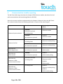
1
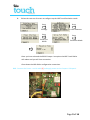
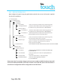
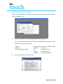
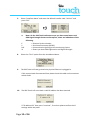
CT-Interface & IRIS Touch 600 Range Installation Manual Coopers I-ON Panel Range Version 2.0 Table of Contents 1 2 3 System Overview ...................................................................................... 3 IRIS Touch 640 PCB Layout ........................................................................ 3 Connections for Coopers I-ON Panel & IRIS Touch..................................... 4 3.1 Power down the Coopers I-ON panel ................................................. 4 3.2 Locate the Coopers I-ON Main PCB as shown below .......................... 4 3.3 Confirm panel version to determine if Break outs are removed ......... 4 3.4 Plug on the CT-Interface board as show in the image ......................... 5 3.5 Plug on IRIS Touch and connect the Power + serial cable [1] ....... Error! Bookmark not defined. 3.6 Ethernet cable (Ethernet / IP connections) [2] ................................... 6 3.7 Install the antenna (GPRS / GSM connection) [3] ............................... 6 3.8 Connect PC / Laptop to the IRIS Touch via the USB connection [4] ..... 6 3.9 Open the IRIS Dialler Configuration software ..................................... 6 3.10 Once you have connected go to the Remote Touch Screen Tab ......... 7 3.11 Perform GPRS Network scan (IRIS Touch 640 only) ............................ 7 3.12 Setting IRIS Touch to Cooper I-ON Emulation mode ........................... 8 3.13 I-ON Panel Configurations ................................................................ 10 3.14 IRIS Touch Configuration & Testing .................................................. 11 4 Communication trouble reporting........................................................... 14 5 Appendix B – Specification ...................................................................... 15 6 Conformance .......................................................................................... 15 Page 2 of 16 1 System Overview The Chiron IRIS Touch range of communicators offers a way of transmitting alarm signals to an monitoring centre over an Ethernet (IP) path, GPRS path. There are two parts to the system: 1. 2. A communication device that connects to the alarm panel. A receiver located within the monitoring centre. The IRIS Touch series of communicators can be connected to the Coopers I-ON panel with the use of the CT-Interface board using the following connection: RS232 interface (5 pin Molex Header running TTL levels), connect between the IRIS Touch and CT-Interface board mounted on the Coopers I-ON panel. The IRIS Touch 640 is capable of signalling over 2 IP paths, Ethernet (usually the clients’ network) and GPRS (mobile Internet). The IRIS Touch 620 signals over Ethernet only. 2 IRIS Touch 640 PCB Layout [2] Ethernet connection (RJ45) [4] USB PC Interface [1] Power + Serial (RS232) connection [3] Antenna (SMA) [5] SIM card Page 3 of 16 3 Connections for Coopers I-ON Panel & IRIS Touch Please follow the following steps to install and configure the communicator. 3.1 Power down the Coopers I-ON panel 3.2 Locate the Coopers I-ON Main PCB as shown below 3.3 Confirm panel version to determine if Break outs are removed Please use the guide below for which panel versions will require removal of the break outs: I-ON 30 I-ON 40 I-ON 50 I-ON 160 = = = = Break outs removed Break outs left on Break outs left on, unless output connectors required Break outs left on Once you have determined the panel, please remove or leave connected the break out option as shown in the image below. Page 4 of 16 3.4 Plug on the CT-Interface board as show in the image 3.5 Plug the IRIS Touch onto the CT-Interface board For panel versions where you have removed the break outs, you can fix the IRIS Touch to a space within the panel enclosure using the sticky feet. If you have not removed the break out, then remove the sticky feet from the IRIS Touch and plug onto the CT-Interface using the standoffs. Next connect the serial cable from the CT-Interface to the Serial port of the IRIS Touch, making sure this is routed under the IRIS Touch as shown. Note: Do not apply power to the Coopers I-On panel until indicated later. Page 5 of 16 3.6 Connect the Ethernet cable (Ethernet / IP connections) [2] Ethernet cable supplied in the box or any standard Cat5 Ethernet cable. 3.7 Install the antenna (GPRS / GSM connection) [3] Connect the standard T-Bar supplied in the box or a High Gain GPRS antenna with SMA connector to improve the signal coverage (see section 3.11, for GSM network scan). Do not fix the antenna in place until you have performed the Run Network Scan, as detailed in section 3.11.4, to confirm best location. 3.8 Note the GPRS antenna shipped (T-Bar) is not meant to be stuck on the panel or within 30cm of any metal surface. Connect PC / Laptop to the IRIS Touch via the USB connection [4] Please ensure that you have download and installed the latest version of the IRIS Dialler Configuration software available from the www.chironsc.com. Please use a standard 2 meter USB A-B cable, which will power the IRIS Touch without having to power-up the panel. 3.9 Open the IRIS Dialler Configuration software You will now see a Chiron adaptor in the connections. Please select and connect, and then continue on the welcome screen. Page 6 of 16 3.10 Once you have connected go to the Remote Touch Screen Tab 3.11 Perform GPRS Network scan (IRIS Touch 640 only) Note: The GSM SIM card should not be installed at this point 1. Select “Installers Menu” and enter the default installer code “111111” and press “OK”. 2. The following screen should now be shown. 3. Note: If not using GPRS as a communication path then please jump to line 10 Select “Run Network Scan” to perform a GPRS network scan for all providers seen from site. After a few minutes, you will be presented with the following screen: You are looking for CSQ values with a minimum of 10 (ideally 12 or greater), for at least 2 base stations for the chosen GPRS SIM provider, or for roaming any 2 base stations. Page 7 of 16 It is recommended that you try the antenna in a number of locations around the IRIS Touch installation, to find the best signal strength for the chosen provider. 4. Fix the antenna in position. 5. Now down power the IRIS dialler. Remove the USB connection 6. Fit the SIM card provided (when GPRS required). Fit the SIM card [5]. 7. Power up the IRIS dialler. Reconnect the USB and connect via the IRIS Dialler Configuration software. 3.12 Setting IRIS Touch to Cooper I-ON Emulation mode Reconnect the IRIS Dialler Configuration and go to the remote touch screen 1. Select “Installers Menu” and enter the default installer code “111111” and press “OK”. Page 8 of 16 2. Follow the next set of screen to configure up the IRIS Touch Emulation mode Press Settings Press Serial Port RS232 Press Panel Interface Press Emulation Mode Once you have selected the RS232 Cooper i-on option the IRIS Touch Dialler will reboot and you will lose connection. Close down the IRIS dialler configuration connection. 3.13 Connect the Power + serial cable [1] and apply power to the Coopers I-ON panel Page 9 of 16 3.14 I-ON Panel Configurations Now configure the panel using the guide below and with the correct information supplied for the site installations. 5 = Communication 1 = ARC Reporting 1 = Call Mode 2 = IP Network 1 = Unit Name 2 = Polling IP Address 3 = ARC IP Address 1 = IP Address 1 2 = IP Address 2 3 = Account Number 1 = Account No P1 4 = Report Type 5 = CID/SIA Events 4 = IP Network (own) 1 = Module: Ethernet 1 = IP Address 2 = Port Number 3 = Subnet Mask 4 = Gateway Address - Enter in the account number for the monitoring centre. - Set this to the IP address of the monitoring centre in a 12 digit format e.g. 80.176.196.135 = 080176196135. - Set this to the IP address of the monitoring Ccentre in a 12 digit format e.g. 80.176.196.135 = 080176196135. - Please leave blank as the IRIS Touch will download the backup address from the monitoring station. - Enter in the account number for the monitoring centre, this must be the same as the unit name. - Set to the alarm format requested by the monitoring mentre or mustomer e.g. Fast Format, Contact ID, SIA (1-2), SC SIA 3 or Ex SIA 3. - Ensure that the relevent Alarm Events you wish to send are enabled. - Program in the IP address for the IRIS Touch 600 range e.g. 192.168.0.10 - Enter the TCP/IP port number for Upload/Download connection. - Enter the subnet mask i.e. 255.255.255.240 - Enter the network gateway IP address e.g. 192.168.001.00 Please note that if you make changes to the account number and ARC IP address these will not be sent down to the IRIS Touch until an alarm is sent from the panel. Once the alarm is sent the new configuration will be configured into the IRIS Touch. Page 10 of 16 IRIS Touch Configuration & Testing Reconnect the IRIS Dialler Configuration and select and connect, and then continue on the welcome screen. 1. For IRIS Touch 640 only if using a IRIS Touch 620 go to step 2: On the communications page please enter the GSM/GPRS Information for the SIM card provider you are using. USER ID Password Access Point Name (APN) 2. Current default APN’s for UK SIM providers: Vodafone = internet O2 = mobile.o2.co.uk Orange = orangeinternet T-Mobile = general.t-mobile.uk Go to the Remote Touch Screen Tab. Page 11 of 16 3. Select “Installers Menu” and enter the default installer code “111111” and press “OK”. Note: On the IRIS Touch welcome screen you have some letters and GSM signal Stength shown on the top line, these are indications of the following: E S Poll Ѱ = Ethernet Synchronisation. = Serial communication (RS232). = Communication (polling) to the monitoring Centre. = Shows you have GSM registration and Signal Strength. 8. Select the “Test” option from the Installation Menu. 9. The IRIS Touch will now go check the physical Ethernet is plugged in. If this reports back disconnected then please check the cable and connections at both ends. 10. The IRIS Touch will now check a valid IP address has been entered. If “IP address OK” then press “continue”, if not then please confirm the IP settings within the panel. Page 12 of 16 11. The IRIS Touch will now perform tests over the Ethernet path to confirm polling and alarm are being received by the monitoring centre. Press Continue If you receive a failed message you will be indicated on the screen some reasons for this, please contact Chiron Technical Support if further assistance is needed. Note: If not using GPRS as a communication path then please jump to line 12 12. The IRIS Touch will now perform a test poll and alarm over the GPRS network. Please confirm both tests pass successfully. Press Continue If you receive a failed message you will be indicated on the screen some reasons for this, please contact the GPRS SIM provider if further assistance is needed. 13. “Test Completed” Click “Finish”. Installation is now completed successfully. Please click the “back” button to return to the welcome screen. The message “Status - System OK” is displayed on the welcome screen and the LED Indicator on the PCB is on steady. You are now ready to do you site commissioning of alarms and any download testing. Page 13 of 16 4 Communication trouble reporting The IRIS Touch 600 range simulates the Coopers 8750 Ethernet module, but allows for dual path communication and monitoring (Ethernet & GPRS). Due to the current interface implemented to the Coopers I-ON panel, when the IRIS Touch has communications faults the following indication is report via the panel keypad. Symptoms Panel Status Monitoring Centre Alarm. IRIS 620: NT9004: Ethernet trouble Ethernet Line Fault Ethernet Synchronisation IP Polling Fault IRIS 640: No indication reported IRIS 620: Ethernet Poll fail IP Polling Fault NT9004: Ethernet trouble NT9014: Ethernet trouble polling No indication reported NT9014: Ethernet trouble polling IRIS 640 only: IRIS 640: NT9003: GPRS Registration No indication reported GPRS trouble IRIS 640 only: IRIS 640: NT9013: GPRS Poll fail No indication reported GPRS trouble polling Ethernet Line Fault NT9004: IP Polling Fault Ethernet trouble IRIS 640 only: Ethernet + GPRS Communication failure IRIS 640 only: Ethernet + GPRS Communication failure Page 14 of 16 IRIS 640: NT9003: GPRS trouble IP Polling Fault NT9014: Ethernet trouble polling NT9013: GPRS trouble polling 5 Appendix B – Specification Ethernet Interface 10Mbps and 100Mbps (10/100BaseT) with auto-negotiation UTP with standard RJ45 socket for CAT-5 cabling Dynamic IP addressing (DHCP) or fixed GSM/GPRS Interface Dual band GSM 900 MHz and DCS 1800 MHz SMA socket for antenna connection IP TCP ports (outbound): 51292 (diagnostics), 52737 (polling), 53165 (alarms), 10001 (Upload/Download). PIN Inputs Maximum input voltage range 0V to +30V Input ‘low’ threshold < 2V Input ‘high’ threshold > 3V Input pull-up impedance Internal 10K to 3.3V supply Relay Outputs Maximum operating voltage 30V Maximum current rating 100mA Power Supply Supply voltage 9 - 30V DC Typical Current (supply at 12v) T620: 120mA T640: 155mA Max Current (supply at 12v) T620: 145mA T640: 185mA Note: These figures are based upon the Ethernet link being connected. With GSM/GPRS there will also be additional transient peak current of up to 250mA required as GSM and GPRS transmissions (e.g. for network registration and calls) are made. Weights Dialer unit 6 T620: 70g T640: 75g Conformance The IRIS Touch range comply with the following Standards: 72/23/EEC Low Voltage Directive 89/336/EEC & 92/31/EEC EMC Directive EN50136-1-1 Alarm transmission EN50131-1 Intruder systems The IRIS diallers conform to Environmental Class II. The IRIS diallers are compliant to ATS 6 compatible with Security Grade 4. The IRIS Touch Range is suitable for use in systems complying to these standards. Page 15 of 16 The future of security, secured IP by security professionals, for the professional security industry Telephone: +44 (0)118 988 0228 E: [email protected] www.chironsc.com Chiron Security Communications Ltd, Wyvols Court, Swallowfield, Reading, Berkshire, RG7 1WY UK The information contained is supplied without liability for any errors or omissions. No part may be reproduced or used except as authorised by contract or other written permission. The copyright and foregoing restriction on reproduction and use extend to all media in which the information may be embedded. © 2011 Chiron Security Communications Ltd Page 16 of 16