1
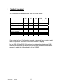
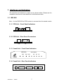
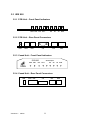
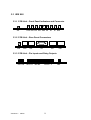
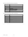
Chiron Technology IRIS 8xx Series Alarm over IP Dialler Installation and User Guide Chiron Technology Wyvols Court Swallowfield Reading UK Tel: E-mail: +44 (0)118 988 0228 [email protected] [email protected] Chiron Technology Ltd 2004 Version 0.7 2/9/05 The information contained is supplied without liability for any errors or omissions. No part may be reproduced or used except as authorised by contract or other written permission. The copyright and foregoing restriction on reproduction and use extend to all media in which the information may be embedded. Table of Contents 1 OVERVIEW 5 2 PRODUCT INVENTORY 6 3 INTERFACES AND INDICATORS 7 3.1 IRIS 800 3.1.1 PCB Unit – Front Panel Indicators 3.1.2 PCB Unit – Rear Panel Connectors 3.1.3 Cased Unit – Front Panel Indicators 3.1.4 Cased Unit – Rear Panel Indicators 7 7 7 7 7 3.2 IRIS 820 3.2.1 PCB Unit – Front Panel Indicators 3.2.2 PCB Unit – Rear Panel Connectors 3.2.3 Cased Unit – Front Panel Indicators 3.2.4 Cased Unit – Rear Panel Connectors 8 8 8 8 8 3.3 IRIS 850 3.3.1 PCB Unit – Front Panel Indicators and Connector 3.3.2 PCB Unit – Rear Panel Connectors 3.3.3 PCB Unit – Pin Inputs and Relay Outputs 9 9 9 9 4 INSTALLATION – ALARM TRANSMISSION AND POLLING OVER IP 11 4.1 Preparation Prior to Installation 11 4.2 Physical Installation 11 4.3 Checking Network Connection 12 4.4 Polling Configuration 13 4.5 Alarm Transmission Configuration 13 5 INSTALLATION – BACKUP TRANSMISSION OVER PSTN OR ISDN 15 5.1 Preparation Prior to Installation 15 5.2 Physical Installation 15 5.3 Checking Network Connection 15 5.4 Alarm Transmission Configuration 15 6 6.1 INSTALLATION – BACKUP POLLING/TRANSMISSION OVER GPRS Preparation Prior to Installation Version 0.7 2/9/05 17 17 2 6.2 Physical Installation 17 6.3 Checking and Network Connection 17 6.4 Polling Configuration 18 6.5 Alarm Transmission 18 7 INSTALLATION – BACKUP TRANSMISSION OVER GSM 19 7.1 Preparation Prior to Installation 19 7.2 Physical Installation and Checking Network Connection 19 7.3 Alarm Transmission 19 8 8.1 ADVANCED INSTALLATION - DATA CALLS Installation 20 20 8.2 Configuration 8.2.1 General 8.2.2 Calls over ISDN using V.120 Rate Adaption 8.2.3 Calls over Ethernet using TCP/IP 8.2.4 Calls over GPRS using TCP/IP 21 21 21 21 22 9 23 ADVANCED INSTALLATION - SMS MESSAGING 9.1 Installation 23 9.2 Configuration 23 10 ALARM PANEL UPLOAD AND DOWNLOAD 25 11 LOCAL CONFIGURATION CONSOLE 26 11.1 Installation of the Local Configuration Console Software 26 11.2 Connecting to the Dialler 26 11.3 Running the Console 26 12 LOCAL CONFIGURATION WITH A TELEPHONE HANDSET 27 12.1 Dialler Default 27 12.2 IP Address 27 13 TROUBLESHOOTING 28 Version 0.7 2/9/05 3 14 SPECIFICATION 29 14.1 Feature comparison 29 14.2 Polling over IP 30 14.3 Alarms over IP 30 14.4 Alarm and Polling Security 30 14.5 Alarm System Upload/Download 30 14.6 Alarm Interface 30 14.7 Ethernet Interface 31 14.8 ISDN Interface 31 14.9 PSTN Interface 31 14.10 GSM/GPRS Interface 31 14.11 SMS Messaging 31 14.12 Data Interface 32 14.13 Pin Inputs 32 14.14 Relay Outputs 32 14.15 LED Status Indicators 32 14.16 Power Supply 32 15 CONFORMANCE AND SAFETY 33 15.1 Conformance 33 15.2 Conformance to EN50131 and EN50136 33 15.3 Safety 34 Version 0.7 2/9/05 4 1 Overview The Chiron IRIS Alarm over IP Dialler range offers a unique way to connect any standard alarm dialler over an IP network, with backup over traditional PSTN or ISDN dial-up networks and/or GSM/GPRS wireless networks if required. An integral polling mechanism is included in all products to provide constant monitoring of the communications paths so that any problems are reported to the ARC. Advanced features such as data calls and SMS messaging are also offered. The full set of features of each model in the range is included in the Specification section at the end of this User Guide. The Installation sections of this Use Guide sets out a straightforward set of instructions for the installer from the most simple installation for alarm transmission over an IP network, through installations with communications backup routes, to more advanced installations which use data call and SMS messaging features of the IRIS range. Version 0.7 2/9/05 5 2 Product Inventory The accessories included with each IRIS unit are as follows: Main IRIS unit Plug top mains power supply Power cable Ethernet cable (cream) Dialler cable (grey) ISDN cable (black) PSTN cable (grey) Velcro mounting Antenna CD IRIS 800 (PCB) IRIS 800 (Cased) IRIS 820 (PCB) IRIS 820 (Cased) IRIS 850 (PCB) • • • • • • • • • • • • • • • • • • • • • • • • • • • • • • • • • Optional • When using the Local Configuration Console, a standard 9-way modem serial cable is required for connection of the IRIS Dialler to a lap-top. For the IRIS 850, the GSM SIM card can be obtained from the chosen GSM network operator. Note that a SIM card offering both GSM and GPRS calls is required to enable the full functionality of the IRIS 850. Version 0.7 2/9/05 6 3 Interfaces and Indicators The interface and indicators on each unit are shown below. Please see the Installation sections for more details on how these are used. 3.1 IRIS 800 Note – for the IRIS 800 the PCB version is narrower than the cased version. 3.1.1 PCB Unit – Front Panel Indicators PWR DIAL ETH POLL ETH 3.1.2 PCB Unit – Rear Panel Connectors DIAL V24 3.1.3 Cased Unit – Front Panel Indicators IRIS 800 DIAL ETH Alarm Adapter POLL RD SD 3.1.4 Cased Unit – Rear Panel Indicators PWR Version 0.7 2/9/05 DIAL V24 ETH 7 TR 3.2 IRIS 820 3.2.1 PCB Unit – Front Panel Indicators PSTN DIAL ETH POLL RD SD TR ISDN 3.2.2 PCB Unit – Rear Panel Connectors PWR PSTN V24 DIAL ETH ISDN 3.2.3 Cased Unit – Front Panel Indicators IRIS 820 PSTN DIAL ETH Alarm Adapter POLL RD SD TR ISDN 3.2.4 Cased Unit – Rear Panel Connectors PWR Version 0.7 2/9/05 PSTN DIAL V24 ETH 8 ISDN 3.3 IRIS 850 3.3.1 PCB Unit – Front Panel Indicators and Connector ANT PSTN DIAL ETH POLL GSM RD SD TR ISDN 3.3.2 PCB Unit – Rear Panel Connectors PWR PSTN DIAL V24 ETH ISDN 3.3.3 PCB Unit – Pin Inputs and Relay Outputs OUT A & B Version 0.7 2/9/05 OUT C & D REF GND INPUTS 1 - 8 9 PWR The function of each indicator is shown in the table below. Name Function PSTN DIAL ETH POLL GSM RD SD TR ISDN PSTN network connection status. Alarm dialler interface status Ethernet connection status Polling status GSM/GPRS connection status Data transmitted on serial port Data received on serial port Serial port connected ISDN network connection status The function of each connector is shown in the table below: Name Function PWR PSTN DIAL V24 ETH ISDN SD OUT INPUTS REF GND Power in PSTN network connection Alarm dialler connection Serial data port Ethernet connection ISDN network connection GSM/GPRS antenna connection Relay outputs Pin inputs 0V reference for inputs Version 0.7 2/9/05 10 4 Installation – Alarm Transmission and Polling over IP 4.1 Preparation Prior to Installation 1. Check that the ARC to which connection is to be made supports Chiron’s IRIS Alarm over IP system. 2. The IP address of the Polling Engine/Receiver at the ARC is required – this will be a twelve digit number. Note – IP addresses are often provided as four numbers separated by the “.” character, e.g. 192.168.3.34. This will need to be converted to a twelve digit equivalent by adding leading zeroes to each number to make them up to three digits each, and then removing the “.”s. The address above becomes 192168003034. 3. The account (“chip”) number is loaded into the alarm dialler – this is the same as required for any standard dialler installation. 4. The IRIS Dialler should be set to factory defaults. If it is believed that the Dialler has been used before on another site and retains that configuration, it should be set to defaults. The way to do this is describer in the Local Configuration sections of the User Guide. 5. The IRIS Dialler has an Ethernet interface for IP network connection that uses Automatic IP addressing (sometimes referred to as DHCP). If Fixed IP addressing is required this can be set up on the IRIS Dialler as described in the Local Configuration sections of this User Guide. 4.2 Physical Installation 1. It is recommended that the IRIS Dialler is located within the same enclosure as the alarm dialler so that it can be powered from the battery backed power supply, protected by the tamper switch and wired directly to the alarm dialler without any external cabling. 2. Make allowances for the external wiring which will be required, i.e. IP network connection via the Ethernet cable. Make sure external cable runs are protected from tampering. 3. If the PCB version of the IRIS Dialler has been selected, use the Velcro fixing strips to mount the Dialler where required. 4. Connect the 2-wire analogue line interface on the alarm dialler to the DIAL input connector on the Dialler using the cable provided (Grey). This cable is terminated at both ends with an RJ11 plug and if the dialler has a connector block rather than an RJ11 socket, the cable can be cut and stripped. The two centre cores should be used and the polarity of the connection is not important. Version 0.7 2/9/05 11 5. The Dialler has the facility to monitor the connection to the alarm dialler so that it can detect disconnection and report this to the ARC. If this facility is required, connect an 18K ohm sense resistor across the 2-wire analogue interface on the alarm dialler. Note – for this feature to work correctly it is essential that this resistor is connected at the alarm dialler end of the cable, not the Dialler end. 6. Use the Ethernet cable provided (Cream) to connect the ETH interface on the IRIS Dialler to the local router, hub, switch etc that gives access to the IP network. The cable provided is terminated at both ends with an RJ45 plug that is the standard interface used for Ethernet connections on most equipment. Make sure this cable run is protected from tampering. Note - it is essential that the Cream cable is used rather than the black (ISDN) cable. 7. Connect the IRIS Dialler to the power source (normally the 12V battery backed supply in the alarm panel) using the cable provided (white stripe is negative). The polarity of connections is important for correct operation, although the Dialler is protected against damage from the application of a reversed polarity power supply. 8. When the power is connected correctly several LEDs on the Dialler come on or start flashing. 4.3 Checking Network Connection 1. A short while after applying power (typically about 10s) the Ethernet interface to the IP network connection can be checked. 2. If this interface is running correctly the ETH LED will be on steady (it may flicker from time to time indicating data flow). 3. If the ETH LED is flashing on/off on a .5s/.5s cycle, then the Ethernet connection has not synchronised. This could be for a number of reasons: • • • Cable not connected properly. Cable connected to wrong device or port on device (e.g. router). Device to which cable connected not switched on. 4. If the ETH LED flashes off briefly every 1s, then this indicates that it is synchronised but has not been given an IP address. The IRIS Dialler may need to be set with a Fixed IP address (see Local Configuration sections). Consult the local Network Manager. Version 0.7 2/9/05 12 4.4 Polling Configuration 1. To start up polling from the IRIS Dialler to the ARC, the Dialler must be loaded with the IP address of the ARC and the account number of the dialler, both of which can be loaded into the IRIS Dialler from the dialler. 2. Make sure the alarm dialler is set up with its account number. Set the IP address of the ARC (i.e. twelve digits) into the ARC telephone number field in the alarm dialler configuration. 3. Trigger the dialler to transmit an alarm. This dialler going off hook is indicated by the DIAL indicator on the IRIS Dialler coming on. The IRIS Dialler will now automatically pick up the account number and IP address from the information transmitted by the dialler and start the polling process to the ARC. 4. Once the IRIS Dialler has successfully completed a poll to the ARC, the POLL indicator comes on and remains on until the next poll. The installer can check that polling is operating correctly by checking that the POLL indicator is on and flickers off briefly (note – it may be so brief as to be unnoticeable) each time a poll is made. 5. If the POLL indicator does not come on, this may be because the wrong account number or ARC IP address have been entered. Set the IRIS Dialler back to factory defaults, check the account number and IP address loaded into the dialler and try again. Alternatively, there could be some IP network connection problem making it impossible for the IRIS Dialler to communicate with the ARC – consult the local Network Manager. 6. The installer does not need to provide other parameters required for polling e.g. polling interval and security key as these are loaded remotely by the ARC when it receives the first polling call. 7. The configuration is stored by the IRIS Dialler in non-volatile memory and will be retained even if power is removed. 4.5 Alarm Transmission Configuration 1. The Polling Engine at the ARC also acts as the receiver for alarm signalling. If the dialler is only required to communicate with a single receiver (i.e. there is no requirement for a backup receiver or second path) then no other configuration is required. 2. Every time the dialler makes a call to transmit an alarm, the DIAL indicator on the IRIS Dialler will come on. Version 0.7 2/9/05 13 3. If a backup or second path is required, the twelve digit IP address of the second receiver should be programmed into the second ARC telephone number field of the dialler. 4. Having set up the alarm transmission as required, it is strongly recommended that all routes are tested by generating alarm signals. During alarm call testing a standard PSTN line monitor can be used to listen in to the alarm communications including ‘handshake’ and ‘kiss-off’ tones to confirm correct operation. Version 0.7 2/9/05 14 5 Installation – Backup Transmission over PSTN or ISDN PSTN or ISDN can be used as a backup for alarm transmission, providing an alternative route to the ARC. Polling does not operate over ISDN or PSTN as this would incur high call charges. The procedures described in this section are in addition to those described in the previous installation section. 5.1 Preparation Prior to Installation 1. For backup alarm transmission over a traditional PSTN or ISDN path, the IRIS Dialler communicates with a standard alarm receiver at the ARC. The telephone number of this receiver will be required. 5.2 Physical Installation 1. If alarm communication over PSTN is required connect the PSTN interface on the IRIS Dialler to the PSTN service using the Grey cable provided. This cable is terminated at both ends with an RJ11 plug and if the PSTN service is connected via a terminal block or Krone strip, the cable can be cut and stripped. The centre two cores should be used and the polarity of the connection is not important. 2. If alarm communication over ISDN is required connect the ISDN network interface on the IRIS Dialler to the ISDN service using the Black cable provided. This cable is terminated at both ends with an RJ45 plug and this is the standard interface for ISDN services. 3. Make sure all cable runs are routed so as the protected against tampering. 5.3 Checking Network Connection 1. If the PSTN connection is connected correctly, then the PSTN LED on the IRIS Dialler will be steady. If the PSTN LED is flashing in a .5s/.5s cycle, then the Dialler cannot see the 50V feed from the PSTN line – check the wiring. 2. If the ISDN LED on the IRIS Dialler is steady then the ISDN connection is synchronised correctly. If the ISDN LED is flashing in a .5s/.5s cycle then there is some problem with the ISDN network or the cabling. 5.4 Alarm Transmission Configuration 1. To select routing of an alarm transmission over PSTN or ISDN, place an extra digit “9” in front of the ARC receiver telephone number programmed into the alarm dialler. This tells the IRIS Dialler that it should route the call over PSTN or ISDN. Note – this method operates based on the fact that an IP address Version 0.7 2/9/05 15 only ever starts with a “0”, “1” or “2’. The IRIS Dialler discards the “9” and dials the call using the subsequent digits. 2. The IRIS Dialler will call over ISDN if this is connected or over PSTN if not. The installer therefore detects the route required (PSTN or ISDN) just by plugging in the appropriate cable. 3. Most alarm diallers allow two ARC numbers to be programmed which can be used in primary/backup mode or for dual path signalling. Various combinations of routing can therefore be set up, depending on the numbers entered: • • • • Version 0.7 Primary and secondary routes over IP. Primary route over IP and secondary route over dial-up PSTN or ISDN. Primary and secondary routes over dial-up PSTN or ISDN. Primary route over dial-up PSTN or ISDN and secondary route over IP. 2/9/05 16 6 Installation – Backup Polling/Transmission over GPRS GPRS can be used as a backup for polling and alarm transmission over IP providing an alternative route to the Polling Engine/Receiver at the ARC. Alarm transmission calls are routed to the same ARC receiver as would be used with ISDN or PSTN. The procedures described in this section are in addition to those described in the previous installation sections. 6.1 Preparation Prior to Installation 1. A SIM card with GPRS support is required from the chosen GSM/GPRS operator. 2. The operator will also provide what is referred to as an “APN” which is a name (e.g. “orangeinternet”) of the gateway between the operator’s GPRS network and the IP network. A User Name and Password may also be required. These will be loaded into the IRIS Dialler. 6.2 Physical Installation 1. Connect the GSM antenna. Route the cable and fix the antenna so as to be protected against tampering. 2. Insert the SIM card into the holder in the IRIS Dialler. If the cased version of the Dialler is being used, the casing can be unscrewed with the four screws under the self-adhesive feet to give access to the SIM card holder. Note – the IRIS Dialler must always be disconnected from power when inserting or removing the SIM card otherwise damage to the SIM card can result. 6.3 Checking and Network Connection 1. The signal strength of the GSM connection can be examined using the Local Configuration Console – see section below. The antenna should be positioned to give best signal strength. 2. Before a GPRS connection can be made, the IRIS Dialler must register with the GSM network. Until registration is complete, the GSM indicator on the IRIS Dialler will flash on/off in a .5s/.5s cycle. 3. Enter the GPRS APN name, User Name and Password (as necessary) using the Local Configuration Console (see section below). 4. If the LED stays flashing then the registration has not occurred. This could be for a number of reasons: Version 0.7 2/9/05 17 • • • SIM card not fitted (or not valid) Antenna not connected Signal strength too low 6.4 Polling Configuration 1. Providing polling over IP has been configured as described in the section above, the IRIS Dialler will automatically poll over GPRS to the same ARC IP address if it cannot complete a poll over IP. 2. The POLL indicator indicates poll success as with polling over IP. 6.5 Alarm Transmission 1. If the IRIS Dialler is unable to make an alarm call over IP, it will automatically retry to the same ARC IP address over GPRS. Version 0.7 2/9/05 18 7 Installation – Backup Transmission over GSM GSM can be used as a backup for alarm transmission, providing an alternative route to the ARC. Polling does not operate over GSM as this would incur high call charges. The procedures described in this section are in addition to those described in the previous installation section. 7.1 Preparation Prior to Installation 1. A SIM card supporting GSM voice calls is required. 7.2 Physical Installation and Checking Network Connection 1. Installation is as for GPRS as described above. Note – the IRIS Dialler must always be disconnected from power when inserting or removing the SIM card otherwise damage to the SIM card can result. 7.3 Alarm Transmission 1. Transmission over GSM is selected by configuring the alarm dialler with one of two leading digits before the telephone number as with PSTN and ISDN. ‘9’ – the IRIS Dialler will route the call over GSM only if PSTN and ISDN are not available. This facility is used for standard GSM backup of PSTN or ISDN lines. ‘7’ – the IRIS Dialler will route the call over GSM whether or not PSTN or ISDN are available. This facility allows a second number programmed in the alarm dialler to force a backup over GSM to overcome possible situations where a PSTN line is available but has been ‘locked’ by an incoming caller. Version 0.7 2/9/05 19 8 Advanced Installation - Data Calls The Dialler supports data transmission either over ISDN (as a standard ISDN Terminal Dialler) or over IP, for applications such as Video Surveillance. This function is separate from the alarm-transmission and SMS features and can be used simultaneously. 8.1 Installation 1. Ensure that the Dialler is connected to the communications network required, either ISDN, Ethernet or GPRS, as described in the Installation section above. 2. Connect the terminal equipment (e.g. the Video Surveillance unit) to the Dialler serial data port (labelled V24) using a standard modem cable. Note the Dialler automatically detects whether the Local Configuration Console software or another device is connected to the serial port. If the serial port has been used for configuration there are no changes that need to be made. 3. Configuration of the Dialler for data calls is via Hayes format commands. This can normally be implemented from the attached. The Hayes commands required for the different networks are shown in the section below. 4. Make a test call – the following activity on the LEDS should be seen: • TR is on (TR may go off temporarily when the call is cleared). • RD and SD flash to show the transfer of data. Version 0.7 2/9/05 20 8.2 Configuration Configuration required for data calls can normally be done by the attached equipment using Hayes commands. Depending on the network being used, the commands are as follows: 8.2.1 General Command Function &F S0=1 S0=0 Sets defaults for data port Sets auto-answer on (if required) Sets auto-answer off (if not required) 8.2.2 Calls over ISDN using V.120 Rate Adaption Command Function %A2=2 Selects V.120 calls over ISDN The number dialled should be the ISDN telephone number of the destination. 8.2.3 Calls over Ethernet using TCP/IP Command Function %A2=12 %I6=abcde Selects TCP/IP calls over Ethernet Sets Dialler TCP port number to abcde (must be five digits from) Sets called TCP port number to fghij (must be five digits) %I7=fghij The number dialled should be the IP address of the destination (12 digits). It is also possible to include the destination TCP port number using the string :fghij immediately after the dialled number, in which case the %I7 register does not need to be set. An example of such a Hayes dial string is: ATD192168001034:01233<CR> This dials IP address 192.168.1.34 on port number 1233. Version 0.7 2/9/05 21 8.2.4 Calls over GPRS using TCP/IP Command Function %A2=19 %I6=abcde Selects TCP/IP calls over GPRS Sets Dialler TCP port number to abcde (must be five digits from) Sets called TCP port number to fghij (must be five digits) %I7=fghij Dialling is as described in the section above. Version 0.7 2/9/05 22 9 Advanced Installation - SMS Messaging SMS support on the IRIS Dialler range provides eight pin inputs that can be used to generate SMS messages and four relay outputs that can be switched on and off by incoming SMS messages. These features can be used for control and monitoring applications, even in locations where no telephone line is present, for example: • • • Control of door lock to allow a caller to enter. Switching heating on and off. Alert on refrigerator failure. 9.1 Installation 1. Select and connect the inputs required using the screw terminal blocks on the IRIS Dialler. Note that inputs 1 to 4 generate messages on the input signal going low and inputs 5 to 8 generate messages on the inputs going high. The block of eight screw terminals next to the pin inputs can be used as reference ground connection if the input signal comes as a pair of wires. 2. Select and connect the outputs required using the screw blocks on the IRIS Dialler. Note that outputs A and B are normally closed and outputs C and D are normally open. 3. If a confirmation SMS message is required when an output is activated, it is suggested that the output is also connected to a spare input. This input can be configured to send a message back to the command originator. 9.2 Configuration Configuration of the SMS functions is done from the Local Configuration Console. Note the following: 1. For input pins both a message and number must be entered otherwise the input will not generate a message when activated. 2. It is recommended that message text contains information about the physical location of the Dialler, as well as the event. This means that the source of the message is immediately clear at the receiving phone. 3. Incoming messages to activate the outputs will be checked against the text string and calling number entered. If no text is entered, no action will be taken on a received message. Calling number checking is an optional security feature and can be disabled by entering nothing in the number field. Version 0.7 2/9/05 23 4. It is recommended that inputs and outputs selected are tested by the installer while on site. Version 0.7 2/9/05 24 10 Alarm Panel Upload and Download Management calls using a standard modem and the alarm panel’s standard management software for upload/download are supported by the IRIS Dialler. Calls can be originated by the dialler and routed via the Dialler over IP or over an ISDN or PSTN dial up link. Alternatively calls can be originated from the management centre and routed to the dialler via IP, ISDN or PSTN. Calls over IP use Voice over IP (VOIP) technology to transport the modem signals over the IP network. For calls originated by the dialler, the Dialler routes the call depending on the format of the telephone number programmed into the dialler: • For routing of calls over IP, the telephone number programmed into the dialler must be the IP address of the receiver prefixed with the digit “8”. • For routing of calls over ISDN or PSTN, the telephone number programmed in the dialler must be telephone number of the receiver prefixed with the digit “9” ‘9’. The routes over PSTN or ISDN , depending on which network is connected. Calls made into the Dialler either over IP, ISDN or PSTN are routed to the DIAL port that will send the ring signal to the dialler in the normal way. For calls over ISDN or PSTN just connect the calling modem into a normal PSTN socket and set the number to dial to the telephone number of the IRIS Dialler to be called. For calls over IP connect via another IRIS Dialler at the calling end. Connect the calling modem to the DIAL socket of the Dialler and ensure the called number is set to the appropriate IP address of the remote Dialler plus the “8” prefix, as described above. Note that if calls are being made into the Dialler over IP, it will need to be allocated a fixed IP address to the Dialler. Please consult the local Network Manager. Version 0.7 2/9/05 25 11 Local Configuration Console 11.1 Installation of the Local Configuration Console Software The Chiron IRIS Dialler configuration software is provided on the CD that is supplied with the unit. To install the software on a PC or Laptop use the following procedure: • Place the CD in the CD ROM drive of the PC or lap-top. • Click the ‘Start’ button and select ‘Run…’. • Click the ‘Browse’ button and open the CD ROM drive (normally D:). • Double click on ‘Setup’ and then click on ‘OK’ to start installation. • Follow the instructions on the screen. 11.2 Connecting to the Dialler Connect the selected COM port on the PC or Laptop to the serial data port on the Dialler using a standard modem cable. 11.3 Running the Console The configuration software can be run from the ‘Start’ button by selecting: Programs > CHIRON IRIS Configuration Console >> CHIRON IRIS Configuration Console version x-x Version 0.7 2/9/05 26 12 Local Configuration with a Telephone Handset Some of the configurations that may be required by the Dialler can be entered by using a standard telephone connected to the ‘DIAL’ port in place of the alarm dialler. Configurations are entered using ‘*’ commands, as follows: 12.1 Dialler Default To set default configuration use: *9**1234567890#. 12.2 IP Address By default the Dialler will automatically negotiate its IP address with the IP network. If a fixed address is required (this address will be allocated by the IT manger), the following commands are used to set the IP address and related IP parameters: • Own IP address: *65*0*nnnnnnnnnnnn# (12 digits) • Sub-net mask: *65*1*nnnnnnnnnnnn# (12 digits) • Default Gateway address: *65*2*nnnnnnnnnnnn# (12 digits) To set back to automatic IP address, use *65*0*#. Version 0.7 2/9/05 27 13 Troubleshooting If problems are experienced, the following guide will be off assistance. Please also refer back to the installation instructions above and check that the correct procedures have been followed. Symptom Possible Causes All LEDs off. No power applied. Check power connection and polarity. On the cable provided, the white stripe indicates negative. No 50V signal applied to dialler. Check cabling between dialler 2 wire connection and DIAL port on Dialler. Dialler reports a Telecom fault. POLL LED does not go on or stay on. Also note that if the Dialler has no network connections (neither Ethernet, ISDN, PSTN nor GSM) it will drop the 50V applied to the dialler to indicate a line error. The Dialler is configured with the wrong Polling Name or Polling Engine IP address. If it is believed that there has been an error in the configuration of the Dialler, it should be defaulted and the procedure repeated. There is a cabling or IP network problem – check the cabling and connections. Dialler does not successfully signal an alarm. There is a polling key mismatch between the ARC and the Dialler. Set Dialler back to default and repeat setup for polling. Also reset ARC entry for this device. The dialler is using the wrong number to call. Check the receiver number settings in the dialler as described in the Installation section above. For calls over IP and GPRS a twelve digit number starting in 0, 1 or 2 should be set. For calls over ISDN, PSTN or GSM the phone number preceded by 9 should be set. The Local Configuration Console does not work. Version 0.7 2/9/05 The selected communications path is not available – check cabling and network connections. Cabling problem between the PC and the Dialler. Check that the correct COM port on the PC and a standard modem cable are being used. The TR LED on the Dialler should be on, and the RD and SD LEDs should flicker as data is transferred between the Dialler and the PC. 28 14 Specification 14.1 Feature comparison The different features of the models in the IRIS 8xx range are shown in the table below. IRIS System Features Supports any panel with Digi Dialler interface Contact ID protocol Fast format (Scancom) SIA (to Level 3) Polling and alarm transmission over Ethernet Automatic backup over GPRS Polling rate configurable Alarm transmission over PSTN or ISDN Alarm transmission over GSM Alarm panel upload/download over IP Alarm panel upload/download over PSTN or ISDN Substitution protection Play-back protection Alarm encryption Tamper proof Battery backup compatible SMS messaging Pin inputs Relay outputs Serial data transmission over IP Serial data transmission over ISDN (Terminal adapter) Voice over IP Automatic configuration Additional configuration via serial port (PC software tool) Additional configuration via analogue port (using phone) Dynamic IP address allocation (DHCP) System and link status LEDs for Installer EN50136 compliant Dual path signalling compliant Version 0.7 2/9/05 29 IRIS 800 IRIS 820 IRIS 850 Y Y Y Y Y Y Y Y Y Y Y Y Y Y Y From 10s From 10s Y Y Y Y Y Y Y Y Y Y Y Y Y Y Y Y Y Y Y Y Y Y Y 8 4 Y Y Y Y Y Y Y Y Y Y Y Y Y Y Y Y Y Y Y Y Y Y Y Y Y Y From 10s Y Y Y Y 14.2 Polling over IP Configurable polling interval (10s to 40mins) set by ARC IP Polling Engine address and account number automatically picked up from alarm dialler Alternative primary and backup numbers can be loaded by ARC Status of all communications links reported to ARC Automatic backup over GPRS Uses TCP connection outbound from IRIS Dialler to port number 52737 at ARC 14.3 Alarms over IP Routing of alarm calls over IP/GPRS or PSTN/ISDN determined by dialled number from alarm system Alarm messages acknowledgement by receiver to ensure reliable transmission Fast Format (Scancom), Contact ID and SIA (to Level 3) supported Primary and backup routes configurable Uses TCP connection outbound from IRIS Dialler to port number 53165 at ARC 14.4 Alarm and Polling Security Protection against substitution on IP networks by authentication using CHAP/MD5 algorithm Alarm messages over IP encrypted with RC4 cyphering Key length up to 256 bits Key loaded by ARC – installer does not need to see key 14.5 Alarm System Upload/Download Management of attached alarm system via incoming or outgoing modem call over PSTN, ISDN or Ethernet. Allows use of standard alarm panel upload/download software. Uses UDP connection with port numbers 8738 and 8739 14.6 Alarm Interface Two wire interface via RJ11 socket 50V feed at 12mA Ringing voltage 60V P-P to REN4 for incoming voice calls Off hook detection with dial-tone presented to alarm dialler DTMF tone recognition for dialling outgoing calls and alarm signalling Tone generation for alarm handshake and “kissoff” tones. Version 0.7 2/9/05 30 14.7 Ethernet Interface 10Mbps and 100Mbps (10/100BaseT) with auto-negotiation UTP with standard RJ45 socket for CAT-5 cabling Auto-sensing of Ethernet 802.2, DIX and SNAP formats ARP (Address Resolution Protocol) support Dynamic IP addressing (DHCP) 14.8 ISDN Interface Basic Rate 2B+D, Q.921, Q.931 ‘S’ bus compatible Conforms to European ETSI standard TBR 3 RJ45 socket with cable provided Point-Point and Point-Multipoint operation Multiple Subscriber Numbering support Data calls using V.120 rate adaption Data calls using PPP asynchronous to synchronous conversion 14.9 PSTN Interface Two wire interface via RJ11 socket Conforms to European ETSI standard TBR 21 Operates at REN 1 Typical line current drawn 14.10 GSM/GPRS Interface Dual band GSM 900 MHz and DCS 1800 MHz Conforms to European ETSI standards MMCX socket for antenna connection Automatic PPP handling for GPRS calls with PAP and CHAP authentication. Outgoing SMS messages on input pin activation Output relay activation on incoming SMS messages 14.11 SMS Messaging Four active low inputs generate SMS messages Four active high inputs generate SMS messages Two normally open relay outputs activated by incoming SMS messages Two normally closed relay outputs activated by incoming SMS messages Optional validation of caller number for incoming SMS messages Version 0.7 2/9/05 31 14.12 Data Interface Asynchronous 9 pin RS232 interface Autobauding to 115.2 Kbps Hayes AT compatible RTS/CTS flow control 14.13 Pin Inputs Maximum input voltage range Input ‘low’ threshold Input ‘high’ threshold Input pull-up impedance 0V to +24V < 2V > 3V Internal 10K to 5V supply 14.14 Relay Outputs Maximum operating voltage Maximum current rating 24V 1A 14.15 LED Status Indicators ETHERNET connection – synchronisation, IP address allocation, data transfer GSM/GPRS – registration, GPRS data transfer ISDN – connection and synchronisation with local exchange PSTN – connection Data port – connection (TR), receive data (SD) and transmit data (RD) Polling – poll call successful, poll complete 14.16 Power Supply Supply voltage IRIS 800 – typical current – dialler on hook IRIS 800 – typical current – dialler off hook IRIS 820 – typical current – dialler on hook IRIS 820 – typical current – dialler off hook IRIS 850 – typical current – dialler on hook IRIS 850 – typical current – dialler off hook 9 - 14V DC 145mA (supply at 12v) 175mA (supply ay 12V) 165mA (supply at 12V) 195mA (supply at 12V) 185mA (supply at 12V) 215mA (supply at 12V) Note – on the IRIS 850 there will also be additional transient peak current of up to 250mA required as GSM and GPRS transmissions (e.g. for network registration and calls) are made. Version 0.7 2/9/05 32 15 Conformance and Safety 15.1 Conformance The IRIS Diallers comply with the following European Directives: 1999/5/EC 72/23/EEC 89/336/EEC (Radio & Telecoms Terminal Equipment Directive) (Low Voltage Directive) (Electromagnetic Compatibility Directive as amended by 92/31/EEC) 15.2 Conformance to EN50131 and EN50136 The IRIS Diallers are compatible with the requirements of European standards prEN50131-1 (Alarm systems – Intrusion and hold-up systems Part 1: System Requirements) (Dated Feb 2004) and EN50136-1-1 (Alarm systems – Alarm transmission systems and equipment) (January 1998 with Amendment 1 August 2001) as follows: The IRIS Diallers conform to Environmental Class II. The IRIS Diallers are compatible with Security Grade 4 providing: • All other system components are also Grade 4 compatible. • The IRIS Dialler is mounted within a Grade 4 enclosure protected by tamper switch and battery backed power supply. • If the PCB variant of the Dialler is used, it should be protected against static discharge by being located within an enclosure such that no part of the PCB is less than 1mm from the enclosure inner surface. • Polling and Alarm Transmission to the ARC is over IP (via the Ethernet connection) or over GPRS. The ARC must also set the polling period such that a communications fault will be detected with 20s. • The 2-wire connection between he IRIS Dialler and the alarm panel is monitored – see Installation section. The ARC should enable monitoring of this connection. Note – In this case the Dialler complies with the highest level of Alarm Transmission System Performance Criteria (ATS6). If GPRS is used as a backup communications path this path should be tested with a test call at least every month. Version 0.7 2/9/05 33 If PSTN or ISDN are used as a backup then the system complies with Performance Criteria ATS 4. The ARC should enable monitoring of this connection. The IRIS Diallers have been assessed and certified against these standards by Telefication B.V. 15.3 Safety Care should be taken that when interconnecting telecommunications equipment that only like interfaces are interconnected to avoid safety hazards. The interfaces on the IRIS Dialler have the following safety classifications: ISDN Interface: TNV operating at SELV and suitable for connection to Basic rate ISDN interfaces provided by a Public Telecommunications Operator or a Private Branch exchange or similar equipment. PSTN Interface: TNV suitable for connection to analogue PSTN interfaces by a Public Telecommunications Operator or a Private Branch exchange or similar equipment. Tel Interface: SELV suitable for connection to the TNV interface of a single line telecommunications equipment such as telephones, faxes etc. Data Interface: SELV suitable for connection to SELV interface on a data terminal such as a PC COM port. Power Interface: SELV for connection to a 12V DC supply. Inputs and Outputs: SELV for connection to alarm output and input pins. TNV (Telecommunications Network Voltage) is defined as a circuit that under normal operating conditions carries telecommunications signals (70.7V peak or 120V dc maximum). SELV (Safety Extra-Low Voltage) is defined as a secondary circuit which is so designed and protected that under normal and single fault conditions the voltage between any two accessible parts does not exceed a safe value (42.4V peak or 60V dc maximum). Version 0.7 2/9/05 34