1
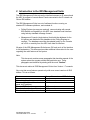
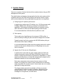
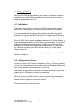
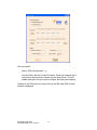
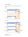
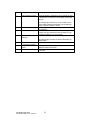
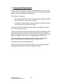
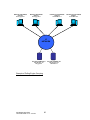
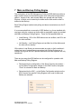
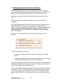
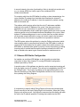
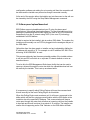
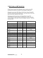
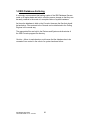
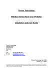
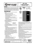
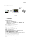
Chiron Technology IRIS Management Suite Technical Guide for the User Chiron Technology Wyvols Court Swallowfield Reading UK Tel: E-mail: +44 (0)118 988 0228 [email protected] [email protected] Chiron Technology Ltd 2007 Version 1.7C 4/11/07 The information contained is supplied without liability for any errors or omissions. No part may be reproduced or used except as authorised by contract or other written permission. The copyright and foregoing restriction on reproduction and use extend to all media in which the information may be embedded. Contents 1 2 3 4 Document Change History ........................................................................ 3 Introduction to the IRIS Management Suite .............................................. 4 System Sizing ............................................................................................ 5 Getting Started .......................................................................................... 7 4.1 Installation .......................................................................................... 7 4.2 Setting up the Licence ........................................................................ 7 4.3 Setting up the System via the Console .............................................. 9 5 Console and Polling Engine Windows..................................................... 10 5.1 Main Windows .................................................................................. 11 5.2 Configuration Selection .................................................................... 13 5.3 System and Console Configuration.................................................. 14 5.4 Polling Engine Configuration ............................................................ 15 5.5 Dialler Configuration ......................................................................... 17 6 Grouping Polling Engines ........................................................................ 19 7 Main and Backup Polling Engine............................................................. 21 8 Polling Overdue Detection and Action..................................................... 24 9 Dialler communications link and poll status reporting ............................. 26 10 Main IP Link Failure Detection and Action ........................................... 28 11 Remote Management Functions.......................................................... 30 11.1 Remote IRIS Dialler Configuration ................................................... 31 11.2 Alarm panel upload/download .......................................................... 32 12 SIA Codes on ARC Serial Link ............................................................ 34 13 Activity Logs ......................................................................................... 35 14 IRIS Database Archiving ...................................................................... 36 15 Technical Reference ............................................................................ 37 15.1 IP Port Number ................................................................................. 37 Iris Management Suite Technical Guide V1.7C 4/11/07 2 1 Document Change History Version Date Changes 1.7C 4/11/07 1.7B 14/7/06 1.7A 31/1/06 Added section to give more details about communications link monitoring and poll overdue handling. Guide to system menus included. Guide to sizing IP link to diallers. Description of operation of dialler remote management and remote voip connection for upload/download of panel. Added IP port numbers used by IRIS system. Added description on new Polling Engine Group function. Added ‘Getting Started’ section. Added recommendations about archiving. Added zone number for IRIS dialler panel interface trouble/restore. Iris Management Suite Technical Guide V1.7C 4/11/07 3 2 Introduction to the IRIS Management Suite The IRIS Management Suite acts as the interface between an IP network and the ARC for support of remote Alarm Panels connected to the IP network via Chiron IRIS diallers. The IRIS Management Suite is a set of software functions running on standard PC hardware platforms, and consists of: • Polling Engines (as many as required), communicating with remote IRIS diallers and signalling to the ARC via a standard serial interface using industry standard message formats. • Management Console (single device) that holds the database for the full system and distributes this database to the Polling Engines as required. The database can either be updated locally on the Console via a GUI or remotely from the ARC via a data file interface. All parts of the IRIS Management Suite have a GUI and much of the interface is self-explanatory. This document provides additional information for the user regarding the main features of the system. Note: This document contains some paragraphs that describe aspects of the system where the operator should take particular care. These paragraphs are identified by starting with the word “Caution”. This document relates to IRIS Management Suites from Version 1.7 onwards. Also note that some features operate only with more recent versions of IRIS diallers. This is as follows: Feature Compatible versions of IRIS diallers Extended polling times Remote call for upload/download of panel via IP gateway Remote IRIS dialler management Panel interface short/open detection Pin alarm input short/open detection V2.12 onwards V2.13 onwards Iris Management Suite Technical Guide V1.7C 4/11/07 V2.8 onwards V2.8 onwards V2.12 onwards 4 3 System Sizing There are a number of factors that should be considered when sizing an IRIS Management Suite system. The details below are based on the assumption that the main system activity is diallers polling into the IRIS Polling Engine and that the amount of alarm traffic (even at peak levels during opening/closing periods) is not significant. 1) Polling Engine PC platform performance. In practice any medium spec PC platform (e.g. 2.5 GHz processor with 512Mbyte RAM) will be adequate, providing it is dedicated to this application. Chiron have successfully tested such a system running with a simulation of 5000 remote diallers polling at 30s intervals. It is recommended that a Windows Server platform is used 2) Disk capacity. This is really only of significance to the storage of IRIS log files, in which all activity including all polls and alarm messages are recorded. Typically a days’ log file for a system with 500 IRIS diallers polling at 60s intervals will be about 40Mbyte. It is recommended that log files should be regularly archived to another medium so the amount actually held on a Polling Engine at any one time is minimised. 3) Speed of the IP link into the Polling Engine. In practice this is most often the main system bottleneck. Each poll requires the transfer of about 250 Bytes (2000 Bits) of data in each direction. Ideally the link should be symmetrical in bandwidth (i.e. same speed in both directions), or at least the sizing should be based on the bandwidth available on the lowest speed direction. Each alarm transmission also requires the same amount of data transfer, but typically the number of alarm transmissions is extremely small compared to the number of polls. Hence alarms are not normally significant in sizing calculations. The diagram below shows the bandwidth (in K bits per second) recommended for different numbers of diallers, depending on the polling frequency. Note – this assumes that the number of alarm messages is not significant, as noted above. Iris Management Suite Technical Guide V1.7C 4/11/07 5 250 IP link bandwidth (Kbits per sec) 200 150 20s polling 60s polling 180s polling 600s polling 100 50 0 50 100 200 500 1000 Number of diallers Iris Management Suite Technical Guide V1.7C 4/11/07 6 2000 5000 4 Getting Started Setting up the IRIS Management Suite is very easy. All software required is contained on a single CD and is installed in the normal way by running the setup.exe applications on the CD. 4.1 Installation The software that should be installed is the IRIS Console (single instance) and the IRIS Polling Engine (on as main hardware platforms as required). It is recommended that the program files should be installed in the default locations (C:\Program Files\IRIS Console and C:\Program Files\IRIS Polling Engine). When the IRIS Console sends an updated database to the Polling Engines, it copies the appropriate files into IRIS Polling Engine directories. It is therefore important that within the operating system, outside of the IRIS application software, the correct access mechanisms and permissions etc. are in place for a file to be copied from the IRIS Console directory to the IRIS Polling Engine directories. It is recommended that this is tested (e.g. by using Explorer) before the IRIS System is configured. 4.2 Setting up the Licence A licence to use the IRIS Console is enabled by Chiron Technology providing a Licence Key that determines the number of remote IRIS diallers that can be set up in the database and the duration of the licence. Alternatively, a demonstration mode can be entered whereby the system will support up to 5 IRIS diallers for a three month period. When first running the IRIS Console, a licence window will be automatically presented. It can be accessed again from the system configuration window should a licence upgrade or renewal be required. The licence window is as shown below: Iris Management Suite Technical Guide V1.7C 4/11/07 7 The user should: Select “IRIS Demonstration”, or Contact Chiron with the Product ID shown. Chiron will respond with a Licence Key that should be entered into the fields shown. This will enable the system for the number of diallers and time period agreed. Clicking on the OK button sets up the licence and the main IRIS Console window is displayed. Iris Management Suite Technical Guide V1.7C 4/11/07 8 4.3 Setting up the System via the Console All system parameters and information about the diallers are held in a database on the IRIS Console, so this has to be set up first. This is done through the Console’s configuration windows and these are described in detail below. Part of this setup is to tell the Console the network addresses of the Polling Engines, so that it knows where to send the database files. Once the setup is complete, or has been changed, it should be downloaded to all the Polling Engines and there is a button within the configuration windows to do this. The successful transfer of the database to the Poling Engines is reported on the main windows of the Console and all the Polling Engines. It is recommended that on the first download all windows are checked to ensure that this transfer has happened properly. Subsequently it should only be necessary to check on the Console itself. Iris Management Suite Technical Guide V1.7C 4/11/07 9 5 Console and Polling Engine Windows This section gives an overview of the functionality of each of the windows used for viewing system operation and setting up the system and dialler database. Subsequent sections give more detail on the operation of specific features of the IRIS system. In general the Console and the Polling Engines use the same window format. However configuration parameters and dialler information is ‘greyed out’ on the Polling Engine windows and can only be changed on the Console, so all changes must be done via the Console. This ensures that there is only one master database and there is no possibility of different devices getting out of step. On the Polling Engines some windows do contain information (e.g. dialler current status) that is specific to that Polling Engine only and not available on the Console. These are explained in the window descriptions below. Iris Management Suite Technical Guide V1.7C 4/11/07 10 5.1 Main Windows The main windows of the Console and the Poling Engines are as shown below: Console: 4 1 5 3 Polling Engine: 4 1 5 2 3 6 7 Iris Management Suite Technical Guide V1.7C 4/11/07 11 Item Purpose Description 1 Dialler database display Shows all diallers in database for group selected in Item 4. Double click on this area to enter dialler configuration window. 2 ARC messages display 3 Monitor display 4 Dialler display filter selection 5 6 7 Access system configuration windows Show connections status Clears adjacent display Iris Management Suite Technical Guide V1.7C 4/11/07 On Polling Engine each entry is colour coded to show current dialler status and the display can be filtered by status criteria as selected in Item 5. Polling Engine only. Shows messages sent to ARC via serial data link. Shows activity for this device (Console or Polling Engine). Can be configured to show all activity or only exception conditions (e.g. poll overdue). Selects which Group of diallers is displayed. On Polling Engine can also be used to filter display by dialler status. Click to enter system configuration windows. Only applies to Polling Engine. Shows status of IP link to diallers and serial link to ARC. The display is cleared but the information remains within the log file. 12 5.2 Configuration Selection System, Console and Polling Engine configuration windows are accessed by clicking on the Edit Config button in the main window. This brings up the Configuration Selection window shown below. 1 2 3 Item Purpose Description 1 Select which device to configure Shows which application is being accessed Close options Click on appropriate button to select what is to be configured. The indicator is highlighted for the application that the user is currently accessing. Applies to Console only. Remember that any changes will not be distributed to the Polling Engines unless the Update Polling Engines option is selected. 2 3 Iris Management Suite Technical Guide V1.7C 4/11/07 13 5.3 System and Console Configuration 1 4 2 5 3 6 Item Purpose Description 1 Determines what is displayed in Console Monitor window Pairs Polling Engines ‘All’ selects everything. ‘Normal’ prevents routine events being displayed. 2 3 4 5 6 Set poll overdue margins Open Licence window Sets up dialler link fail detection Exit options Iris Management Suite Technical Guide V1.7C 4/11/07 This setting is not essential, it just aids selection of main and backup Polling Engines on the Dialler Configuration window. Single setting that applies to all Polling Engines. See further description in section below. Console only. Opens the Licence window to show current licence or to update licence. Enables detection of failure of the IP link from the diallers. See more details in section below. This must be set to prevent an IP link failure resulting in multiple poll overdue events. Applies to Console only. Remember that any changes will not be saved unless the correct option is selected. 14 5.4 Polling Engine Configuration 1 2 9 3 4 10 5 11 6 7 8 12 Item Purpose Description 1 Polling Engine name Free text field. 2 Sets Polling Engine Group number within which this Polling Engine sits Polling Engine network location See section below for description of Group function. 3 4 Sets which type of PSTN receiver the Polling Engine emulates 5 Determines format of messages sent to ARC for events such as Poll Overdue 6 Setup of serial port to be used with communications with ARC Set rack number to be used for this polling engine on ARC serial interface 7 Iris Management Suite Technical Guide V1.7C 4/11/07 Tells the Console where to send the database files for this Polling Engine. Use the browse facility and click on the IRIS Polling Engine.exe icon. If this field has no entry, the Console assumes this Polling Engine does not exist and does not try to send it the database. For compatibility with existing ARC software, the Polling Engine emulates industry standard PSTN receivers on the serial interface. The options are: • Surguard – MLR2 • Radionics – D6600 • Transparent – text only, e.g. for printer Messages for poll status changes or comms status changes on the diallers are sent as SIA event messages to the ARC, as described in the section below. Optionally a SIA text message can also be sent as well for each event. Messages sent to the ARC in Surguard and Radionics emulations include a rack number and line card number. The Polling engine always sets line card 1 and the rack number can be set from 0 to 63. 15 8 9 Sets the account number used for reporting system events Dialler link IP address System events, which are not dialler specific, such as dialler link fail are reported to the ARC on this account number. This is the IP address that will be sent to any dialler that is told to use this Polling Engine as its main or backup. If the Polling Engine sits behind an address translating gateway or firewall, this must be the ‘public’ IP address on the other side of the gateway. Note – the facility to validate this address by making a test call to the address entered is automatically offered. 10 11 12 To tell which diallers to accept polls from Determines what is shown in the Polling Engine monitor window Exit options Iris Management Suite Technical Guide V1.7C 4/11/07 Caution – it is vital that this address is correct or diallers may not be able to communicate with the system as required. Normally set to ‘Own Diallers’, i.e. diallers for which this is the main Polling Engine, so that polls overdues are only reported to the ARC from one Polling Engine. This prevents possible confusion in the ARC if a dialler temporarily polls into its backup Polling Engine due to some transient IP network problem. In the event of the main Polling Engine completely failing, this can be set to ‘All Diallers’ to ensure that the Backup Polling Engine now reports any poll overdues and keeps the ARC updated. ‘All’ selects everything. ‘Normal’ prevents routine events being displayed. Remember that any changes will not be saved unless the correct option is selected. 16 5.5 Dialler Configuration The Dialler Configuration window is accessed by double clicking on the dialler database display area on the main window. Information relating to the particular dialler on which the pointer sits will be displayed. This window is used to add a new dialler, prior to installation, or to subsequently modify a dialler set up. It is important that the dialler is setup prior to installation or the installation process will not complete successfully. 1 8 2 3 9 10 4 11 5 12 6 7 13 Item Purpose Description 1 Gives dialler unique identification within its group Free text field. This information is also required by the installer so it can also be set up in the dialler. 2 3 Sets Polling Engine Group number within which this dialler sits Security key This window has a scroll button to allow any other dialler in the database to be selected. See section below for description of Group function. Free text key that secures communication between IRIS dialler and Polling Engine, providing both authentication and encryption of messages. The key can be changed at any time and the new key will be uploaded to the dialler when it next polls in. Iris Management Suite Technical Guide V1.7C 4/11/07 17 The Last Valid Key field shows the actual key in use by the dialler. Note this field is only refreshed when this window is opened. 4 5 Set main and backup Polling Engines for this dialler Sets polling interval 6 Automatically adds more database entries 7 8 Save or delete dialler Free text area for description of dialler Dialler remote access functions 9 10 Sets which dialler interfaces are monitored so that status changes are reported to ARC as Trouble/Restore. For maximum security it is recommended that the key length should be 32 characters, each dialler has a unique key and all keys are changed regularly. See section below for more details. Can be changed at any time and changes will be sent to the dialler when it next polls in. Note that extended polling intervals (above 40 minutes) are only supported by diallers version 2.12 and above. Database entries will be added in incremental numerical order from the one displayed. All parameters (security key etc) will be the same. Save current dialler settings or delete current dialler For reference only, e.g. site details, customer details, key holder info etc A set of commands that activate remote access functions for the dialler, e.g. configuration over IP or access to alarm panel for upload/download. See section below for more detail. ISDN: Dialler interface to ISDN line. PSTN: Dialler interface to PSTN line. Ethernet: Dialler interface to Ethernet. GPRS: Dialler interface to GPRS network. Panel: Dialler two wire interface to panel, short or open circuit detection – note this requires sense resistor to be fitted at the panel end of the connection – see IRIS Dialler Installation Guide- applies to diallers version 2.8 and later. Pin Inputs: Dialler pin input short or open circuit detection - note this requires sense resistors to be fitted at the remote end of the input lines – see IRIS Dialler Installation Guide – applies to diallers version 2.12 and later. 11 Shows current dialler interface status 12 Edit dialler or profile 13 Exit options Iris Management Suite Technical Guide V1.7C 4/11/07 Note - the actual interfaces available on a dialler depend on the actual dialler type (IRIS 800, 840 etc). Applies to Poling Engine only. Shows status irrespective of whether the monitoring boxes (as above) are ticked. This information is only refreshed when this window is opened. Option to allows definition of a default profile which can be applied to new or existing diallers to make setup easier. Remember that any changes will not be loaded into the Polling Engines unless the correct option is selected. 18 6 Grouping Polling Engines In some cases it is desirable to be able to duplicate dialler account numbers so that more than one dialler can use the same account number and yet each can be uniquely identified by the IRIS System. This could be, for example: • For very large systems where the number of diallers installed is greater than the number of account codes available. • To support an existing estate of diallers where it is convenient to leave the existing account numbers unchanged. To support this facility, Polling Engines and diallers are assigned to a group. Up to 256 groups are allowed. A group of Polling Engines would typically include a Main and Backup (or two load sharing units) and will be given unique IP addresses when installed. To ensure that a dialler connects to the correct group, the IP address set into the dialler on installation must be one of the Polling Engines of that group. This is exactly analogous with traditional PSTN systems where different groups of diallers are given different telephone numbers to dial. An example is shown in the diagram below. Group numbering is set up via the IRIS Console, both in the Polling Engine configuration window and the Dialler Configuration window. Iris Management Suite Technical Guide V1.7C 4/11/07 19 MAIN POLLING ENGINE GROUP 0 IP xxx.yyy.zzz.1 BACKUP POLLING ENGINE GROUP 0 IP aaa.bbb.ccc.1 MAIN POLLING ENGINE GROUP 1 IP xxx.yyy.zzz.2 IP NETWORK ACCOUNT NUMBER 1973 SET TO POLL TO xxx.yyy.zzz.1 Example of Polling Engine Grouping Iris Management Suite Technical Guide V1.7C 4/11/07 20 ACCOUNT NUMBER 1973 SET TO POLL TO aaa.bbb.ccc.1 BACKUP POLLING ENGINE GROUP 1 IP aaa.bbb.ccc.2 7 Main and Backup Polling Engine The combination of the IRIS Management Suite and IRIS diallers provides a highly resilient alarm communication system with multi-path communication options. As part of this, each remote dialler can operate with two Polling Engines, of which one is treated by the dialler as the Main and the other is treated as the Backup. Each Polling Engine handles both polling and alarm transmission over the IP network. It is recommended that a community of IRIS diallers (e.g. those installed with one large multi-site customer or those within a geographic region) is provided with Main and Backup Polling Engines. These can be operated either as: • Load Sharing - 50% of the IRIS diallers use one as Main, and 50% use the other as Main. • Hot Standby – one Polling Engine acts as Main for all the diallers and the other sits on standby. Of the above, Load Sharing is recommended as under no-fault conditions it makes best use of network resources and as both Polling Engines are in constant use it gives the ARC operator assurance that both systems are fully operational. There are two ways that IRIS diallers can be configured for operation with Main and Backup Polling Engines: • Determined by the configuration of the Alarm Panel by the installer – on the Dialler Configuration window on the IRIS Console, the option “Panel” is selected for Main and Backup. • Determined by the ARC – on the Dialler Configuration window on the IRIS Console, the specific Polling Engines to be used for Main and Backup are selected. Iris Management Suite Technical Guide V1.7C 4/11/07 21 These two options operate in different ways: Alarm Panel determined: This is the default mode of operation. The IRIS dialler uses only one Polling Engine for Polling and two Polling Engines for Alarm Transmission. Polling Engine IP addresses are determined by the installer – see IRIS Dialler Installation Guide. For Polling, the Polling Engine used is determined by the IP address loaded into the IRIS dialler by the installer. For Alarm Transmission the Polling Engine used is determined by the IP addresses loaded into the Alarm Panel. This operates in exactly the same way as traditional PSTN communications. Depending on exactly what facilities the Alarm panel supports this allows: • Transmission of alarms to Main Polling Engine with fallback to Backup if this transmission does not succeed. • Transmission of alarms to both Main and Backup Polling Engines. Iris Management Suite Technical Guide V1.7C 4/11/07 22 ARC determined: This mode allows the ARC to override the settings put in by the installer. Irrespective of the address loaded by the installer, for each poll the IRIS dialler will try first the Main Polling Engine, and retry if the initial attempt fails. It will then try the Backup Polling Engine. On the next poll this procedure will be repeated, i.e. the polling will be restored to the Main as soon as it recovers. For each alarm call, irrespective of the addresses loaded into the panel by the installer, the IRIS dialler will first try the Main Polling Engine and if this fails will immediately try the Backup Polling Engine. The Main and Backup addresses will be automatically loaded into the IRIS dialler when it polls in. If they are subsequently changed by the ARC, the new addresses will be loaded on the next poll. Note that this facility allows the ARC to hide the Main and Backup IP addresses from the installer. A special “commissioning” Polling Engine can be set up, and it is the IP address of this Polling Engine that is given to the installer. On the first poll, the dialler will be reconfigured with the actual Main and Backup IP addresses, unknown to the installer. Caution – the ARC operator must take extra care that valid IP addresses are loaded as if the IRIS dialler has the wrong IP addresses it will not be possible to communicate with it and a site visit will be required. It is strongly recommended that if the setup is changed it is tested on one easily accessible IRIS dialler before being applied to the full community. Iris Management Suite Technical Guide V1.7C 4/11/07 23 8 Polling Overdue Detection and Action The Polling Engine expects each remote IRIS dialler to poll in at the time interval specified within the database loaded from the Console. If a poll is not received, the Polling Engine reports this as a Poll Overdue to the ARC. When polls are again received, the Polling Engine reports a Poll OK to the ARC. The ARC therefore only sees state changes and is not inundated with messages. The Polling Engine makes allowance for the fact that a poll may be delayed, and allows extra time margin over the polling period, before reporting overdue. This extra margin allows for such things as transient network delays, longer delays if the polling is over GPRS, or delays because the Polling Engine is a Backup for the IRIS dialler which first times out while trying its Main Polling Engine. The amount of margin can be set as a system wide parameter on the Console. The way this operates is as follows: • For shorter polling periods, the margin is a proportion of the polling period. • For longer polling periods, the margin is a fixed period, as a percentage would give unnecessarily large overdue reporting times. The threshold between these actions can also be changed. If the poll period is less than the threshold, the percentage is used. If the poll period is greater or equal to the threshold, the fixed time is used. It is recommended that a typical setting for high security systems is a 60s poll with margin of 100%. This means that any communications problem with the remote alarm system will be reported in 120s, which is well within the 180s required with the EN 50131 standards for the highest security grade (Grade 4). Iris Management Suite Technical Guide V1.7C 4/11/07 24 For lower security systems a longer polling time can be used. By default, Polling Overdue and Polling Restore for each remote IRIS dialler are only reported by the Polling Engine acting as Main for that dialler. Some ARC systems cannot differentiate Polling Overdue or Polling OK messages seen on the serial links from the Main and Backup Polling Engines and this mechanism prevents potential confusion at the ARC in situations where, for example, there was a transient network problem and the IRIS dialler failed to connect to Main and so polled to the Backup. In circumstances where there has been a major failure at the site where the Main Polling Engine is located and no polls can get through, if the ARC wishes the Secondary Polling Engine to report Polling Overdue and Polling OK, this can be enabled by setting the Polling Accept option for that Polling Engine to “All Diallers”. Iris Management Suite Technical Guide V1.7C 4/11/07 25 9 Dialler communications link and poll status reporting On every poll, a dialler reports its communications interface status to the Polling Engine and these are shown in the Status area of the IRIS Dialler Configuration screen for the dialler, as shown below. Each interface is monitored on the dialler as follows: Interface Monitoring method ISDN Checks that low level communication with the local exchange (at Layer 2) is possible. Does not incur any call costs. Checks line voltage. Checks: Ethernet is synchronised (i.e. connected). And: Polling over Ethernet is possible, i.e. end-end connection with ARC is operational. Checks that GSM is registered with the local base station. Checks that the connection is not open or short circuit. Note – for this to operate correctly a sense resistor must be fitted at the end of line, as described in the dialler installation guide. Checks that each input is not open or short circuit. Note – for this to operate correctly sense resistors must be fitted at the end of each line, as described in the dialler installation guide. PSTN Ethernet GSM Panel Pin Inputs If the equivalent box in the Monitor section is ticked and the status changes, then an appropriate trouble/restore message is sent to the ARC, coded as described in “SIA Codes on ARC Serial Link” section below. Iris Management Suite Technical Guide V1.7C 4/11/07 26 The colour coding of the diallers as shown on the main Polling Engine window are derived from the status and the poll state: Colour Meaning Green Polling OK (not overdue) and all communications interfaces which are ticked in Monitor are OK. Polling OK (not overdue) but at least one of the communications interfaces which are ticked in Monitor is not OK. Polling overdue but all communications interfaces which are ticked in Monitor are OK. Yellow Brown Red For example, a situation that would cause this would be where the dialler suddenly stops polling because it has been physically disabled by all power being removed. Polling overdue and at least one of the communications interfaces which are ticked in Monitor is not OK. This is the status that will be seen before the dialler polls for the first time. Alternatively, red will be seen if a dialler with a communications interface problem (e.g. with GSM) goes poll overdue. Iris Management Suite Technical Guide V1.7C 4/11/07 27 10 Main IP Link Failure Detection and Action The Polling Engine has a mechanism to detect a failure of the IP link into which the IRIS diallers poll. Failure is determined to have occurred when no polls have been received within a timeout period. The failure is reported to the ARC via the serial link and during the failure period Poll status changes are not reported to the ARC. This prevents ‘flooding’ of the ARC with Poll Overdue messages while the IP link is in failure. When the IP link is restored, the Polling Engine waits for a ‘Soft Start’ period to elapse before starting to report Poll status changes. This gives a period during which all remote IRIS diallers can reconnect and the system can stabilise. This mechanism is enabled by setting the Dialler Link Timeout and Soft Start periods on the Console configuration menu. By default these are set to 0, i.e. are disabled. When deciding what settings to use, the following should be considered: • The Timeout period should be longer than the shortest poll period. This prevents a false reporting of link failure, even when the system is handling only a small number of remote diallers. • The Timeout period should be less than the shortest Poll Overdue reporting time (i.e. Poll period plus Overdue Margin). This means that Link Failure will be reported before any Poll Overdue reports. Poll Overdue reports will then be suspended until the link is restored. Iris Management Suite Technical Guide V1.7C 4/11/07 28 • The Soft Start period should be set according to the number of remote diallers to be supported by the Polling Engine. Recommended settings are: 500 or less: 50s 1000 or less: 100s 5000 or less: 500s If by chance there has been a failure at a remote IRIS dialler during the failure or Soft Start period then this will be reported at the end of the Soft Start period. Also note that any Alarm messages received within the Soft Start period will be forwarded to the ARC. Iris Management Suite Technical Guide V1.7C 4/11/07 29 11 Remote Management Functions One of the problems with IP networking that the IRIS system solves is how to make a remote management call into the IRIS dialler or the attached alarm panel when the dialler is on a private network behind a router that is the gateway to the public Internet. Such as situation is very common, ranging from very big networks (e.g. a retailer’s network with hundreds of sites) to very small networks (e.g. a home network with an ADSL line and a couple of PCs). This is illustrated below: POLLING ENGINE AT ARC INSTALLER’S SITE IP ADDRESS 10.45.78.156 IP ADDRESS 10.5.67.89 PUBLIC INTERNET POLLING AND ALARM CALLS IP ADDRESS 10.1.123.5 REMOTE MAINTENANCE CALLS ROUTER PRIVATE NETWORK IP ADDRESS 192.168.0.3 IP ADDRESS 192.168.0.2 IRIS DIALLER The IP addresses within the private network are allocated automatically (dynamically by DHCP). The IP addresses externally are fixed public IP addresses. Iris Management Suite Technical Guide V1.7C 4/11/07 30 In a small network, the router functionality is likely to be built into another unit, e.g. on a home ADSL line it will be part of the combined ADSL modem/router/firewall. For outgoing calls from the IRIS dialler for polling or alarm transmissions, the router receives IP packets from the dialler and translates the internal IP address to the external IP address. It does the opposite for packets coming back on the same call. The problem with incoming calls is that the only IP addresses available externally is the public IP address of the router. How does an external application set up a connection to a specific device behind the router ? This can be achieved by what is called port mapping within the router, but this requires specific set up and detailed technical knowledge of the router. When dynamic IP address assignment is used, or when there are multiple devices on the private network behind the router, all of which need to be accessed from time to time, this becomes very difficult or impossible to achieve. The IRIS system solves this problem by using the Polling mechanism (which uses outgoing calls) to carry back instructions to the IRIS dialler to make an outgoing call to the address on the public network from which access to the IRIS dialler or attached alarm panel is required. Hence the problem of making incoming calls is avoided and through the polling mechanism the ARC can help an installer who wants to gain remote access for maintenance etc. 11.1 Remote IRIS Dialler Configuration An installer can configure IRIS diallers on site by making a serial data connection to them from a laptop PC running IRIS dialler configuration software provided by Chiron. A special version of this software can also be used to accept an incoming call from the dialler over the IP network. This call can be instigated by the ARC via the Polling Engine. This is done by setting up the appropriate entries in the Remote Access are of the Dialler Configuration window on the Console and then updating the Polling Engines: It is necessary to specify which Polling Engine will issue the command and this will normally be the main Polling Engine for this dialler. When this Polling Engine next receives a poll, it will issue the command and the dialler will make the call to the IP address specified. Providing the installer has the IRIS Iris Management Suite Technical Guide V1.7C 4/11/07 31 configuration software set waiting for an incoming call then the connection will be made and the installer can proceed as though connected normally. At the end of the session either the installer can just disconnect or the call can be cleared by the ARC using the Stop Dialler Management command. 11.2 Alarm panel upload/download IRIS Diallers support upload/download over IP using the alarm panel manufacturer’ own upload download software. The way this is achieved is by passing the upload/download modem signal, as used on a PSTN connection, transparently over the IP network using VOIP (Voice over IP) technology embedded in all IRIS diallers. All that is required at the installer’s site is another IRIS dialler. The modem the installer would normally use on PSTN is plugged into the analogue dial port of the IRIS dialler. Calls either from the alarm panel or installer end are instigated by dialling the IP address with a prefix of ‘8’. For example to call IP address 192.168.0.3 the dial string ‘8192168000003’ is used. This process obviously has the same potential problem if the installer wishes to call into an IRIS unit which is on a private IP network behind a router as described above. To solve this, the IRIS Management Suite has a facility that can be used to open up a channel through the router via which the upload/download call can be made by the installer. This is set up as shown below. It is necessary to specify which Polling Engine will issue the command and this will normally be the main Polling Engine for this dialler. When this Polling Engine next receives a poll, it will issue a command to the dialler which will start an outgoing communication with the IRIS dialler at the installer’s site at the specified IP address. This communication will keep a route open through the router that will allow an incoming call from the installer to be made and this will continue for a period of 15 minutes. The installer can confirm this is happening as the ‘Dial’ indicator on the IRIS dialler will flash. Iris Management Suite Technical Guide V1.7C 4/11/07 32 The installer then dials from the upload/download software in the normal way, but rather than using the leading ‘8’ followed by a full IP address, just uses the leading ‘8’ followed by a further ‘8’. The IRIS dialler at the installer site will recognise this special case and pass a call through the router to the remote IRIS unit targeted. The call then proceeds as normal. Iris Management Suite Technical Guide V1.7C 4/11/07 33 12 SIA Codes on ARC Serial Link Polling Engines transmit Alarm Messages via the serial link to the ARC according to the serial link emulation in use (Surguard or Radionics). Messages received from IRIS diallers in Fast Format, Contact ID and SIA formats are transmitted without modification, in the same way as if they had been received by a standard PSTN receiver. Messages generated internally by the Polling Engine to report Poll Overdue/Restore or dialler interface Trouble/Restore use SIA event code format messages. As an option a SIA text message is only semt. These are as shown below: EVENT SIA DATA ZONE TYPE CODE NUMBER TEXT MESSAGE IRIS Dialler Polling Overdue IRIS Dialler Polling OK YC YK 9001 9001 POLLING Overdue POLLING Restore IRIS ISDN Comms Trouble IRIS PSTN Comms Trouble IRIS Ethernet Comms Trouble IRIS GSM/GPRS Comms Trouble IRIS Panel Interface Trouble IRIS Pin Input Trouble NT NT NT 9001 9002 9004 NT 9003 ISDN Comms Trouble PSTN Comms Trouble ETHERNET Comms Trouble GPRS Comms Trouble NT NT 9006 9007 PANEL Comms Trouble PIN INPUTS Trouble IRIS ISDN Comms Restore IRIS PSTN Comms Restore IRIS Ethernet Comms Restore IRIS GSM/GPRS Comms Restore IRIS Panel Interface Restore IRIS Pin Input Restore NR NR NR 9001 9002 9004 NR 9003 ISDN Comms Restore PSTN Comms Restore ETHERNET Comms Restore GPRS Comms Restore NR 9006 PANEL Comms Restore NR 9007 PIN INPUTS Restore Polling Engine IP Link Trouble Polling Engine IP Link Restore NT 9102 NR 9102 Iris Management Suite Technical Guide V1.7C 4/11/07 34 13 Activity Logs IRIS Polling Engines and Console maintain logs of activity. These are written to files in the Monitor sub-directory within the directory where the relevant programme file resides. A new log file is created for each day and each event is time-stamped. Caution – these log files use up storage area on the PC disk and care should be taken that files are archived to other machines and deleted on a regular basis so that disks do not become full, as this would prevent to correct operation of the IRIS System. Iris Management Suite Technical Guide V1.7C 4/11/07 35 14 IRIS Database Archiving It is strongly recommended that backup copies of the IRIS Database files are made on a regular basis and held in off site or secure storage so that they can be easily restored in the event of a complete failure of system hardware. As the entire database is held on the Console, these are the files that should be backed up. Files restored to the Console can be distributed to the Polling Engines in the normal way. The appropriate files are held in the Devices and System sub-directories of the IRIS Console program file directory. Caution – failure to make backups could mean that the database has to be recreated from scratch in the event of a system hardware failure. Iris Management Suite Technical Guide V1.7C 4/11/07 36 15 Technical Reference This section contains technical details about the IRIS System that the user may require. 15.1 IP Port Number IP port numbers used within the IRIS system are as follows: Polling: Port 52737 (TCP) Alarm transmission: Port 53165 (TCP) Remote configuration: Port 51292 (TCP) Panel upload/download: Ports 8738 and 8739 (UDP) Iris Management Suite Technical Guide V1.7C 4/11/07 37