1
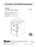
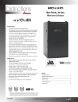
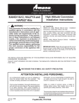
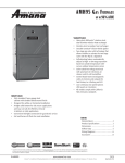
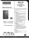
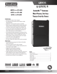
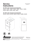
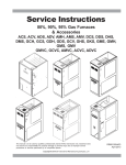
WGFM19
95% AFUE GAS FURNACE
PRODUCT SPECIFICATIONS
The Whirlpool® brand WGFM19 Upflow / Horizontal
Convertible multi-speed gas furnaces provide
exceptional indoor comfort. This quiet furnace
delivers a money-saving efficiency of up to 95%
AFUE.
Standard Features
•
•
•
•
•
•
•
•
HEATING INPUT:
46,000–115,000 BTU/H
•
•
Patented stainless-steel, dual-diameter tubular heat
exchanger with lifetime limited furnace replacement warranty
Two-stage gas valve with revolutionary new convertible
technology that allows installer to activate the two-stage
valve with the flip of a dipswitch
Silicon Nitride igniter with patented adaptive learning
control for maximum igniter life
Furnace control board with self-diagnostics, colorcoded low-voltage terminals, and provisions for
electronic air cleaner and 24-volt humidifiers
Control board stores the last five diagnostic codes in
memory; simple push-button activation outputs the fault
history to a flashing red LED
4 Speed PSC Multispeed Blower Motor
Self-adjusting feature automatically adjusts to high or low
stage based on outside temperature without an outdoor
temperature sensor
Dual-certified for sealed combustion direct vent
(2-pipe) or non-direct vent (1-pipe) applications
Easy-to-install top venting is standard; alternate flue/vent
located on the right
All models comply with California NOx emissions standards
Cabinet Features
•
•
•
•
•
Fully insulated, heavy-gauge steel cabinet with durable
baked-enamel finish
Designed for multi-position installation: upflow, horizontal
left or right
Airtight solid bottom for side return applications and easycut tabs for effortless removal in bottom air inlet applications
Convenient left or right connection for gas/ electric service
Coil and furnace fit flush for most installation
* To receive the Lifetime Unit Replacement Limited Warranty and 10-Year Parts Limited
Warranty, online registration must be completed within 60 days of installation. Online
registration is not required in California or Québec. Full warranty details are available
at www.whirlpoolhvac.com.
WGFM19.00
www.whirlpoolcomfort.com
10/09
PRODUCT SPECIFICATIONS
NOMENCLATURE
W
G
F
M
1
95
045
S
3
B
X
*
*
1
2
3
4
5
6,7
8,9,10
11
12
13
14
15
16
Engineering
Major Revision
Minor Revision
Brand
W Whirlpool
Product Category
G Gold
Revisions
A Initial Release
B 1st Revision
C 2nd Revision
Description
F Furnace
NOx
N Natural Gas
X Low NOx
Airflow Direction
D Dedicated Downflow
M Upflow/Horizontal
Description
1 Single Stage
AFUE
95 95%
A
B
C
D
Cabinet Width
14”
17½”
21”
24½”
Maximum
3
4
5
CFM @ 0.5” ESP
1,200
1,600
2,000
MBTU/h
045: 45,000
070: 70,000
090: 90,000
2
Blower
E EEM Multispeed
S PSC Multispeed
V ECM Variable
Speed
115: 115,000
140: 140,000
www.whirlpoolcomfort.com
WGFM19.00
PRODUCT SPECIFICATIONS
SPECIFICATIONS
WGFM195
045S3BX
WGFM195
070S3BX
WGFM195
070S4CX
WGFM195
090S4CX
WGFM195
090S5CX
WGFM195
115S5CX
46,000
44,600
39,330
95
3
35 - 65
69,000
66,400
58,995
95
3
30 - 60
69,000
66,400
58,995
95
4
35 - 65
92,000
89,000
78,660
95
4
30 - 60
92,000
88,400
78,660
95
5
35 - 65
115,000
110,500
98,325
95
5
35 - 65
10” X 8”
¹⁄₃
10” X 8”
¹⁄₃
10” X 10”
½
10” X 10”
½
11” X 10”
¾
11” X 10”
¾
4
2”
2
4
2”
3
4
2”
3
4
2”
4
4
3”
4
4
3”
5
290
580
288
580
385
770
385
770
480
960
480
960
9.4
15
132
9.4
15
135
13.8
15
136
13.8
15
158
13.2
15
172
13.2
15
175
Heating Capacity
Input¹
Natural Gas Output¹
LP Gas Output¹
AFUE²
Available AC @ 0.5” ESP
Temperature Rise Range (°F)
Circulator Blower
Size (D x W)
Horsepower @ 1750 RPM
Speed
Vent Diameter³
No. of Burners
Filter Size (in2)
Permanent4
Disposable
Electrical Data
Min. Circuit Ampacity 5
Max. Overcurrent Device (amps)6
Ship Weight (lbs)
1
2
3
4
5
6
Natural Gas BTU/h. For altitudes above 2,000’, reduce input rating 4% for each 1,000’ above sea level. Low-fire rate is 75% of high-fire rate
DOE AFUE based upon Isolated Combustion System (ICS)
Vent and combustion air diameters may vary depending upon vent length. Refer to the latest editions of the National Fuel Gas Code NFPA 54/ANSI Z223.1
(in the USA) and the Canada National Standard of Canada, CAN/CSA B149.1 and CAN/CSA B142.2 (in Canada).
Permanent air filter size is based on 600 FPM velocity. Check with filter manufacturer for specific details.
Minimum Circuit Ampacity = (1.25 x Circulator Blower Amps) + ID Blower amps. Wire size should be determined in accordance with
National Electrical Codes. Extensive wire runs will require larger wire sizes.
Maximum Overcurrent Protection Device refers to maximum recommended fuse or circuit breaker size. May use fuses or HACR-type
circuit breakers of the same size as noted.
Notes
• All furnaces are manufactured for use on 115 VAC, 60 Hz, single-phase electrical supply.
• Gas Service Connection ½” FPT
• Important: Size fuses and wires properly and make electrical connections in accordance with the National Electrical Code
and/or all existing local codes.
WGFM19.00
www.whirlpoolcomfort.com
3
PRODUCT SPECIFICATIONS
DIMENSIONS
28 3/4
19 7/8
22 1/16
FOLDED FLANGES
FOLDED FLANGES
23 9/16
UNFOLDED FLANGES
UNFOLDED FLANGES
LEFT SIDE VIEW
FRONT VIEW
Model
D
E
A
B
RIGHT SIDE VIEW
C
D
E
WGFM195045S3BX
17½”
16”
13¹⁄₈”
12¹⁄₈”
13⁵⁄₈”
WGFM195070S3BX
17½”
16”
13¹⁄₈”
12¹⁄₈”
13⁵⁄₈”
WGFM195070S4CX
16¹⁄₈”
16”
17½”
21”
19½”
WGFM195090S4CX
21”
19½”
16¹⁄₈”
16”
17½”
WGFM195090S5DX
24½”
23”
20⁵⁄₈”
19³⁄₈”
20⁷⁄₈”
WGFM195115S5DX
24½”
23”
20⁵⁄₈”
19³⁄₈”
20⁷⁄₈”
Notes:
• Installer must supply one or two PVC pipes: one for combustion air (optional) and one for the flue outlet (required). Vent pipe must be either 2” or 3” in
diameter, depending upon furnace input, number of elbows, length of run, and installation (1 or 2 pipes). The optional combustion air pipe is dependent on
installation/code requirements and must be 2” or 3” diameter PVC.
• Line voltage wiring can enter through the right or left side of furnace. Low-voltage wiring can enter through the right or left side of furnace.
• Conversion kits for high-altitude natural gas operation are available. Contact your Whirlpool distributor or dealer for details.
• Installer must supply the following gas line fittings, according to which entrance is used:
Left: One 90º street elbow; one 2½” pipe nipple; one 90º elbow; straight pipe; one ground joint union
Right: Straight pipe to reach gas valve
• Installations using a bottom return: Failure to unfold flanges will reduce airflow area by approximately 18%. This could result
in performance and noise issues.
MINIMUM CLEARANCES TO COMBUSTIBLE MATERIALS
Position
Sides
Rear
Front
Bottom
Flue
Top
Upflow
0”
0”
1”
C
0”
1”
Horizontal
6”
0”
1”
C
0”
4”
C = If placed on combustible floor, the floor MUST be wood ONLY.
Notes:
• For servicing or cleaning, a 24” front clearance is recommended.
• Unit connections (electrical, flue, and drain) may necessitate greater clearances than the minimum clearances listed above.
• In all cases, accessibility clearance must take precedence over clearances from the enclosure where accessibility
clearances are greater.
• Approved for line contact in the horizontal position.
4
www.whirlpoolcomfort.com
WGFM19.00
PRODUCT SPECIFICATIONS
BLOWER PERFORMANCE SPECIFICATIONS
(CFM & Temperature Rise vs. External Static Pressure)
Model
WGFM195
045S3BX
WGFM195
070S3BX
WGFM195
070S4CX
Motor
Speed
Tons AC
at 0.5”
ESP
External Static Pressure, (Inches Water Column)
0.1
0.2
0.3
0.4
0.5
0.6
0.7
0.8
CFM
Rise
CFM
Rise
CFM
Rise
CFM
Rise
CFM
Rise
CFM
CFM
CFM
High
3
1,352
29
1,318
30
1,260
31
1,202
33
1,128
35
1,044
955
853
Med
2.5
1,214
32
1,172
34
1,123
35
1,064
37
1,012
39
938
859
741
Med-Lo
2
997
40
994
40
960
41
923
43
884
45
817
741
611
Low
1.5
757
52
753
52
734
54
704
56
674
59
620
524
438
High
3
1,449
41
1,409
42
1,326
45
1,273
47
1,201
49
Med
2.5
1,192
50
1,172
51
1,141
52
1,094
54
1,046
57
973
904
793
Med-Lo
2
981
61
962
62
943
63
917
65
888
67
830
764
665
Low
1.5
750
79
730
81
714
83
692
86
657
90
620
570
502
High
4
2,069
29
1,965
30
1,871
32
1,756
34
1,661
36
1,549 1,415 1,275
Med
3.5
1,752
34
1,724
34
1,667
36
1,603
37
1,488
40
1,402 1,290 1,082
Med-Lo
3
1,437
41
1,437
41
1,417
42
1,369
43
1,320
45
1,256 1,140
984
Low
2.5
1,184
50
1,177
50
1,161
51
1,132
52
1,095
54
1,047
837
1,194 1,136 1,018
928
Notes:
• CFM in chart is without filter(s). Filters do not ship with this furnace, but must be provided by the installer.
• All furnaces ship as high-speed cooling and medium-speed heating. Installer must adjust blower cooling and heating speed as needed.
• For most jobs, about 400 CFM per ton when cooling is desirable.
• INSTALLATION IS TO BE ADJUSTED TO OBTAIN TEMPERATURE RISE WITHIN THE RANGE SPECIFIED ON THE RATING PLATE.
• The chart is for information only. For satisfactory operation, external static pressure should not exceed value shown on the rating plate.
• The above chart is for U.S. furnaces installed at 0-2000 feet. At higher altitudes, a properly de-rated unit will have approximately the same temperature rise
at a particular CFM, while ESP at the CFM will be lower.
WGFM19.00
www.whirlpoolcomfort.com
5
PRODUCT SPECIFICATIONS
BLOWER PERFORMANCE SPECIFICATIONS (CONT.)
(CFM & Temperature Rise vs. External Static Pressure)
Model
Motor
Speed
High
Med
WGFM195
090S4CX Med-Lo
Low
High
Med
WGFM195
090S5DX Med-Lo
Low
High
Med
WGFM195
115S5DX Med-Lo
Low
4
3.5
3
2.5
5
4
3.5
3
0.1
CFM Rise
1,970 40
1,713 46
1,439 55
1,183 67
2,147 37
1,675 47
1,489 53
1,307 61
External Static Pressure, (Inches Water Column)
0.2
0.3
0.4
0.5
0.6
CFM Rise CFM Rise CFM Rise CFM Rise CFM
1,874 42 1,757 45 1,667 48 1,566 51 1,431
1,650 48 1,572 50 1,510 52 1,418 56 1,313
1,412 56 1,370 58 1,327 60 1,260 63 1,166
1,155 69 1,122 71 1,108 72 1,062 75 1,011
2,114 37 2,057 39 2,030 39 1,978 40 1,889
1,686 47 1,640 48 1,623 49 1,557 51 1,501
1,470 54 1,436 55 1,409 56 1,361 58 1,318
1,265 63 1,234 64 1,203 66 1,168 68 1,096
0.7
CFM
1,334
1,211
1,078
931
1,784
1,455
1,243
1,053
0.8
CFM
1,182
1,079
956
816
1,713
1,360
1,130
991
5
4
3.5
3
2,134
1,678
1,453
1,259
2,103
1,643
1,440
1,239
1,733
1,423
1,253
1,082
1,625
1,339
1,205
1,015
Tons AC
at 0.5”
ESP
46
58
68
78
47
60
68
79
2,029
1,643
1,426
1,220
48
60
69
80
1,941
1,577
1,363
1,181
51
62
72
83
1,906
1,527
1,349
1,159
51
64
73
85
1,818
1,489
1,314
1,118
Notes:
• CFM in chart is without filter(s). Filters do not ship with this furnace, but must be provided by the installer.
• All furnaces ship as high-speed cooling and medium-speed heating. Installer must adjust blower cooling & heating speed as needed.
• For most jobs, about 400 CFM per ton when cooling is desirable.
• INSTALLATION IS TO BE ADJUSTED TO OBTAIN TEMPERATURE RISE WITHIN THE RANGE SPECIFIED ON THE RATING PLATE.
• The chart is for information only. For satisfactory operation, external static pressure should not exceed value shown on the rating plate.
• The above chart is for U.S. furnaces installed at 0-2000 feet. At higher altitudes, a properly de-rated unit will have approximately the same temperature rise
at a particular CFM, while ESP at the CFM will be lower.
CONFIGURATION & OPERATION
6
www.whirlpoolcomfort.com
WGFM19.00
PRODUCT SPECIFICATIONS
WIRING DIAGRAMS
BLO WER
COMPARTMENT
DOOR SWITCH
(OPEN WHEN
DOOR OPEN)
OR
24 VAC
HUMIDIFIER
GY
24 VAC
INTEGRATED
CONT ROL MODULE
HUMIDIFIER
TR (6)
GND
GND (8)
C
MVC (9)
115 VAC
24V THERMOSTAT
CONNECTIONS
C
GAS
VALVE
PM
W
R
G
BK
GY
3
OFF
2
1
6
5
4
9
8
7
11
12
2ND
STAGE
DELAY
MODE
HEAT
OFF
DELAY
*
*
GR
OR
G
PS (10)
HLI (7)
W
HLO (1)
R
RO2 (11)
RO1 (5)
TH (3)
24 VAC
40 V A
TRA NSFORMER
WH
XFMR-H
115 VAC
WH
FS
HOT SURFACE
IGNITER
IGN
BK
WH
OR
WH
GY
OR
BL
BK
BR
BR
GR
RD
PK
RD
YL
BK (HI)
BL (MED)
OR (MED LOW)
RD (LOW)
YL
HE LO
AT
-H
COOL-H
PU
BLOWER COMPARTMENT
EAC-H
MANUAL RESET
AUXILIARY LIMITS
(1) IN UPFLOW
BLOWER DECK
(2) IN C'FLOW
BLOWER HOUSING
BURNER COMPARTMENT
GND
BK
CIRCULATOR
BLWR
CIR-N
H I -H
AT
HE
OR
WH
CAPACITOR
ID-N
ID
BLWR
IND
ELECTRONIC
AIR CLEANE R
INTEGRATED CONTROL MODULE
INTEGRATED CONTROL MODULE
SEE
NOTE 4
XFMR-N
FLAME SENSOR
HEAT-H
LINE-H
NO
C
PSO (4)
TO
MICRO
Y
PK
XFMR-H
1
SEE
NOTE 6
GND
ID BLOWER
PRESSURE
SW ITCH
BR
115 VAC NEUTRAL
TERMINALS
FS
115 VAC HOT AND PARK TERMINALS
COOL-H
NO
XFMR-N
2
*
YL
10
RD
GY
OR
FACTORY SETTINGS
SHOWN
DIAGNOSTIC
LED
BL
OR
GY
*
PK
OR
24V THERMOSTAT CONNECTIONS
OR
INTEGRATED
CONTROL
MODULE
C
FRONT COVER
PRESSURE SWITCH
BK
WH
FUSE
ON
MVL(2)
C
Y
BK
BR
HI
MVH (12)
EAC-N
LINE-N
L INE-H
JUNCTION BOX
DOOR
SWITCH
WH
WH
INDUCED DRAFT
BLOWER
DIS CONNECT
WH
PU
BL
L
YL
RD
N
O
GND
N
TO 115VAC/ 1 Ø /60 HZ POWER SUPPLY WITH
OVERCURRENT PROTECTION DEVICE
OR
OR
C
RD
PK
WH
ID BLOWER
24 VAC
PRESSURE
HUMIDIFIER
SWITCH
2 CIRCUIT
CONNECTOR
HOT
SURFACE
IGNITER
0
1
PM
JUNCTION
BOX
BL
1
GY
C
2
BR
HI
3
N
O
C
FRONT COVER
PRESSURE SWITCH
GY
GND
STEADY ON = NORMAL OPERATION
= CONTROL FAILURE
=
LOW VOLTAGE (24V)
LOW VOLTAGE FIELD
2
2 FLASHES = PRESSURE SWITCH STUCK CLOSED
HI VOLTAGE (115V)
3
3 FLASHES = PRESSURE SWITCH STUCK OPEN
HI VOLTAGE FIELD
4
4 FLASHES = OPEN HIGH LIMIT
5
5 FLASHES = FLAME SENSE WITHOUT GAS VALVE
6
6 FLASHES =
7
7 FLASHES = LOW FLAME SIGNAL
C
CONTINUOUS/RAPID FLASHES = REVERSED 115 VA C POLARITY
COLOR CODES:
YL YELLOW
OR ORANGE
PU PURPLE
GN GREEN
BK BLACK
PK PINK
BR BROWN
WH WHITE
BL BLUE
GY GRAY
RD RED
0140F00098 REV.--
L
FLAME
SENSOR
OR
1 FLASH
N
GND
BK
GAS VALVE
OFF
WH
GR
EQUIPMENT GND
FIELD GND
FIELD SPLICE
SWITCH (TEMP.)
JUNCTION
TERMINAL
INTERNAL TO
INTEGRATED CONTROL
PLUG CONNECTION
IGNITER
SWITCH (PRESS.)
OVERCURRENT
PROT. DEVICE
NOTES:
1. SET HEAT ANTICIPATOR ON ROOM THERMOS TAT AT 0.7 AMPS.
2. MANUFACTURER'S SPE CIFIED REPLACEMENT PARTS MUST BE USED WHEN SERVICING.
3. IF ANY OF THE ORIGINAL WIRE AS SUPPLIED WITH THE FURNACE MUST BE REPLACED, IT MUST BE REPLACED WITH WIRING MATERIAL
HAVING A TEMPERATURE RATING OF AT LEAST 105 °C. USE COPP ER CONDUCTORS ONLY.
4. IF HEATING AND COOLING BLOWER SPE EDS ARE NOT THE SAME, DISCARD JUMPER B EFORE CONNECTING BLOWER LEADS. UNUSED
BLOWER LEADS MUST BE PLACED ON "PARK" TERMINALS OF INTEGRATED CONTR OL OR TAPED.
5. UNIT MUST BE PERMANENTLY GROUNDED AND CONFORM TO N.E.C. AND LOCAL CODES.
6. TO RECALL THE LAST 5 FAULT S, MOST RECENT TO LEAST RECENT, DEPRESS SWITCH FOR MORE T HAN 2 SECO NDS W HILE IN
STANDBY (NO THE RMOSTAT IN PUT S)
Wiring is subject to change. Always refer to the wiring diagram on the unit for most up-to-date wiring.
WARNING
HIGH VOLTAGE!
Disconnect all power before servicing or installing this unit.
Multiple power sources may be present.
Failure to do so may cause property damage, personal injury, or death.
WGFM19.00
www.whirlpoolcomfort.com
7
PRODUCT SPECIFICATIONS
ACCESSORIES
Model
WGFM195 WGFM195 WGFM195 WGFM195 WGFM195 WGFM195
045S3BX 070S3BX 070S4CX 070S4CX 090S5DX 115S5DX
Description
LPM-03B
LP Conversion Kit (Gas Valve)
√
√
√
√
√
√
LPM-05
LP Conversion Kit (Springs & Orifice)
√
√
√
√
√
√
LPLP01
LP Gas Low Pressure Kit
√
√
√
√
√
√
FTK03A
Twinning Kit
√
√
√
√
√
√
ASAS
Electronic Air Cleaners
√
√
√
√
√
√
AMU
Media Air Cleaners
√
√
√
√
√
√
HANG11
High Altitude Natural Gas Kit
1
1
1
1
1
1
HANG12
High Altitude Natural Gas Kit
2
2
2
2
2
2
HALP10
High Altitude LP Gas Kit
3
3
3
3
3
3
HAPS27
High Altitude Pressure Switch Kit
3
3
3
3
3
3
EFR01
External Filter Rack
√
√
√
√
√
√
DCVK-20
Horizontal/Vertical Concentric Vent Kit (2”)
√
√
---
---
---
---
DCVK-30
Horizontal/Vertical Concentric Vent Kit (3”)
√
√
√
√
√
√
017K00000S
Flush-mount Vent Kit
√
√
√
√
√
√
Notes:
√ Indicates available for this model
1 Indicates 7,001’ to 9,000’ altitude
2 Indicates 9,001’ to 11,000’ altitude
3 Indicates 7,001’ to 11,000’ altitude
All installations above 7,000’ require a pressure switch change. For installation in Canada, furnaces are certiÞed only to 4,500’.
Whirlpool® is a trademark of Whirlpool Corporation and used under license to Tradewinds Distributing Co. LLC. All rights reserved. Our continuing commitment
to quality products may mean a change in specifications without notice. © 2009 • Tradewinds Distributing Co. LLC. • Jacksonville, FL • Printed in the USA.
8
www.whirlpoolcomfort.com
WGFM19.00