1
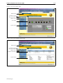
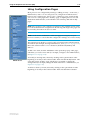
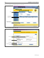
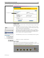
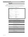
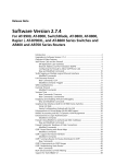
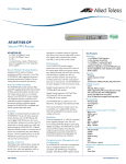
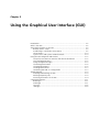
Chapter 3
Using the Graphical User Interface (GUI)
Introduction ................................................................................................... 3-2
What is the GUI? ........................................................................................... 3-2
Accessing the Router via the GUI ................................................................... 3-3
Browser and PC Setup ............................................................................. 3-3
Establishing a Connection to the Router .................................................. 3-5
Secure Access ........................................................................................ 3-10
System Status and System Hardware Details .......................................... 3-10
Using the GUI: Navigation and Features ....................................................... 3-12
The Quick Start Menu on AR750S and AR750S-DP Routers ................... 3-12
The Configuration Menu ....................................................................... 3-12
Using Configuration Pages .................................................................... 3-13
The Management Menu ........................................................................ 3-16
The Monitoring Menu ........................................................................... 3-16
The Diagnostics Menu ........................................................................... 3-17
Combining GUI and CLI Configuration .................................................. 3-17
Troubleshooting ........................................................................................... 3-18
Enabling and Disabling the GUI ............................................................. 3-18
Deleting Temporary Files ........................................................................ 3-18
Accessing the Router via the GUI ........................................................... 3-19
Command Reference ................................................................................... 3-21
disable gui ............................................................................................. 3-21
enable gui ............................................................................................. 3-21
reset gui ................................................................................................ 3-22
show gui ............................................................................................... 3-23
3-2
AlliedWare OS Software Reference
Introduction
You can set up, manage, monitor, and troubleshoot the router using the
command line interface (CLI) or the web-based GUI. The GUI includes the
commonly-required functions for a number of protocols. You can access the
GUI using HTTP, for local or remote access or HTTPS, for secure remote access
GUIs are available on the AR725, AR745, AR750S and AR750S-DP. No GUI is
available on the AR770S.
This section describes the basic functionality of the GUI, including:
■
What is the GUI?
•
■
■
an introduction to the Graphical User Interface
Accessing the router via the GUI:
•
browser and PC setup, including interaction with HTTP proxy servers
•
establishing a connection to your router, including information about
configuring SSL for secure access
•
the System Status page, the first GUI page you see
•
diagnosing and solving connection problems
Using the GUI: navigation and features:
•
an overview of the menus
•
using configuration pages, with a description of key elements of GUI
pages
•
combining GUI and CLI configuration
See Chapter 1, Getting Started for information about
■
changing your password
■
using the context sensitive online help
■
saving your configuration
What is the GUI?
The GUI (Graphical User Interface) is a web-based device management tool
designed to make it easier to configure and monitor the router. The GUI
provides an alternative to the CLI (Command Line Interface). Its purpose is to
make complicated tasks simpler and regularly performed tasks quicker.
The GUI relies on an HTTP server that runs on the router, and a web browser
on the host PC. When you use the GUI to configure the router, the GUI sends
commands to the router and the router sends the results back to your browser,
all via HTTP.
The tasks you may perform using the GUI are not as comprehensive as the
command set available on the CLI, but for some protocols, a few clicks of the
mouse are adequate. An example is the ease with which you can configure an
ISDN link.
The GUI is stored on the router in the form of an embedded resource file, with
an .rsc file extension. Resource files are model-specific, with the model and
version encoded in the file name.
Software Version 2.8.1
C613-03119-00 REV A
Using the Graphical User Interface (GUI)
3-3
Accessing the Router via the GUI
To use the GUI to configure the router, you use a web browser to open a
connection to the router’s HTTP server. Therefore, you need a PC, a web
browser and the router. Supported browsers and operating systems, and the
settings you need on your PC and browser, are detailed in the following
section. Router setup is detailed in “Establishing a Connection to the Router”
on page 3-5.
Browser and PC Setup
The GUI requires a web browser installed on a PC. Table 3-1 shows supported
combinations of operating system and browser.
Table 3-1: Supported browsers and operating systems
IE 5.0
IE 5.5
IE 6.0
NS 6.2.2
NS 6.2.3
Windows 95
!
Windows 98
!
!
!
Windows ME
!
!
!
!
!
Windows 2000
!
!
!
!
!
Windows XP
!
!
!
!
!
JavaScript must be enabled. To enable JavaScript in Internet Explorer:
1.
From the Tools menu, select Internet Options.
2.
Select the Security tab.
3.
Click the Custom Level button.
4.
Under the Scripting section, ensure that “Active scripting” is enabled.
To enable JavaScript in Netscape 6.2.x:
1.
From the Edit menu, select Preference.
2.
Select the Advanced menu option.
3.
Ensure that the “Enable JavaScript for Navigator” checkbox is checked.
The minimum screen resolution on the PC is 800x600.
Pop-up Windows
Pop-up windows must be allowed. If you are using a toolbar or plug-in on
your browser to block pop-ups, disable it while using the GUI. The GUI
displays detailed configuration options and information in pop-up windows.
Either turn the toolbar off or specify that pop-ups are allowed for the IP
address of the router. To turn off a toolbar on Internet Explorer 6, select
Toolbars from the View menu and make sure the toolbar is not checked.
Software Version 2.8.1
C613-03119-00 REV A
3-4
AlliedWare OS Software Reference
HTTP Proxy Servers
An HTTP proxy server provides a security barrier between a private network’s
PCs and the Internet. The PCs send HTTP requests (and other web traffic) to
the server, which then forwards the requests appropriately. Similarly, the server
receives incoming HTTP traffic addressed to a PC on the private network, and
forwards it to the appropriate PC. Proxy servers can be used to block traffic
from undesirable web sites, to log traffic flows, and to disallow cookies.
If your browser is configured to use a proxy server, and the router is on your
side of the proxy server, you must set the browser to bypass proxy entries for
the IP address of the appropriate interface on the router. See “Establishing a
Connection to the Router” on page 3-5 for information about giving router
interfaces IP addresses.
Caution To ensure that your network’s security settings are not compromised,
see your network administrator for information about bypassing the proxy
server on your system.
To bypass the proxy server on Internet Explorer, if your browser administration
does not use a script, and the PC and the router are in the same subnet:
1.
From the Tools menu, select Internet Options.
2.
Select the Connections tab and click the LAN Settings button.
3.
Check the “Bypass proxy server for local addresses” checkbox.
4.
If necessary, click the Advanced button and enter a list of local addresses.
To bypass the proxy server on Netscape, if your browser does not use a script:
1.
From the Edit menu, select Preferences.
2.
Click the Advanced menu option to expand it.
3.
Select the Proxies menu option.
4.
Enter the router’s IP address in the “No Proxy for” list.
Software Version 2.8.1
C613-03119-00 REV A
Using the Graphical User Interface (GUI)
3-5
Establishing a Connection to the Router
Before you start, consider how the router fits into your network. If you are
installing a new router, consider whether you want to configure it before
deploying it into the LAN, or want to configure it in situ. If you want to access
a router that has already been configured, consider the relative positions of the
PC and the router. The flow chart below summarises this process, and the
procedures that follow take you through each possibility in detail.
Figure 3-1: A summary of the process for establishing a connection via the GUI.
Start here
Is the router
already installed and
configured in
the LAN?
Yes
Determine the IP address
of an interface on the router
and browse to it.
See “Option 3: Connecting
to an Installed Router” on
page 3-9.
Yes
Connect your PC directly to
the router, give the router an
IP address and browse to it.
See “Option 1: Configuring
the Router before
Installation” on page 3-6.
No
Do you want
to configure the router
before installing it in
the LAN?
No
Install the router into the LAN,
give it an IP address and
browse to it.
See “Option 2: Installing
the Router into the LAN”
on page 3-7.
Software Version 2.8.1
C613-03119-00 REV A
3-6
AlliedWare OS Software Reference
The AR750S and AR750S-DP have default IP configuration for their default
VLAN. To see the default configuration, and a procedure for using the GUI to
connect via the router’s switch ports, see the router’s Installation and Safety
Guide.
Option 1: Configuring the Router before Installation
Use this procedure if:
■
you want to configure the router before installing it in your LAN
■
you want to install the router at a remote office or a customer site and want
to configure it first
■
you want a dedicated management PC permanently connected to the
router
■
you want to use the GUI to connect to the Eth port on an AR750S or
AR750S-DP router. If you want to use the default VLAN, which has an IP
address assigned by default, see the router’s Installation and Safety Guide.
1.
Select a PC to browse to the router from.
You can browse to the router from any PC that is running a supported
operating system with a supported browser installed. See “Browser and
PC Setup” on page 3-3 for more information.
You need to know the subnet of the PC.
2.
Connect the PC to the router.
Use a straight-through Ethernet cable to connect an Ethernet card on the
PC to any one of the switch ports (see Figure 3-2).
Use a straight-through Ethernet cable to connect an Ethernet card on the
PC to any one of the Ethernet ports (see Figure 3-2).
Figure 3-2: Connecting a PC directly to the router
straight-through cable
STATUS
ETHERNET
ENGINE
ACT DAT
ERR
CLR
10
COL
TX
PORTS
INTERFACE MODULES
Tx
SYN
Rx
PWR RUN SYS
SEC
FD
LNK
D
PRI
DISCONNECT MAINS SUPPLY BEFORE REMOVING
LID. CONTAINS NO USER SERVICEABLE PARTS
E1/T1
AR700 router
B
ACT
NT
RX
BASE
BAY 1
BAY 0
POWER
ETH port
PC
Important You can browse to the router through any ETH port, or any VLAN
on the AR750S or AR750S-DP, as long as you give that interface an IP address
(below). These instructions assume you are using eth0 as the LAN interface.
3.
Access the router’s command line interface.
Access the CLI from the PC, as described in your Installation and Safety
Guide or Quick Install Guide.
4.
Enable IP.
enable ip
5.
Assign the eth0 interface an IP address in the same subnet as the PC.
add ip interface=eth0 ip=ipaddress mask=mask
Software Version 2.8.1
C613-03119-00 REV A
Using the Graphical User Interface (GUI)
6.
3-7
Save the configuration and set the router to use it on bootup.
create config=your-name.cfg
set config=your-name.cfg
7.
On the PC, bypass the HTTP proxy server if necessary.
See “HTTP Proxy Servers” on page 3-4 for more information.
8.
Point your web browser at the LAN interface’s IP address.
9.
At the login prompt, enter the user name and password.
The default username is manager:
User Name: manager
Password: friend
The System Status page or System Hardware Details page is displayed
(Figure 3-6 on page 3-11). Select options from the sidebar menu to
configure and manage the router.
Option 2: Installing the Router into the LAN
Use this procedure if:
■
You want to install the router into the LAN before you configure it.
■
On an AR750S or AR750S-DP, if you want to use the GUI to connect to the
Eth port. If you want to use the default VLAN, which has an IP address
assigned by default, see the AR700 Series Router Installation and Safety
Guide.
1.
Select a PC to browse to the router from.
You can browse to the router from any PC that is running a supported
operating system with a supported browser installed, with JavaScript
enabled. See “Browser and PC Setup” on page 3-3 for more information.
You need to know the PC’s subnet.
2.
Plug the router into the LAN.
To install the router into the same subnet as the PC:
Use an Ethernet cable to connect one of the Ethernet ports to a device on the
LAN segment, for example, a hub, router or switch (see Figure 3-3).
Figure 3-3: Connecting the router into the same LAN segment as the PC.
4
3
2
STATUS
ETHERNET
ENGINE
1
ACT DAT
ERR
CLR
10
COL
TX
PORTS
INTERFACE MODULES
Tx
SYN
Rx
PWR RUN SYS
OFF
SEC
FD
LNK
BAY 1
POWER
ETH port
PC
Software Version 2.8.1
C613-03119-00 REV A
Hub or Layer 2
Switch
D
B
RX
BASE
POWER
PRI
10BASE-T/100BASE-TX SWITCH PORTS
E1/T1
DISCONNECT MAINS SUPPLY BEFORE REMOVING
LID. CONTAINS NO USER SERVICEABLE PARTS
ON
AR700 Series Router
BAY 0
ACT
NT
3-8
AlliedWare OS Software Reference
To install the router into a different subnet than the PC:
Use an Ethernet cable to connect any one of the Ethernet ports to a device
on the LAN segment in which you require the router to work, for example,
a hub, router, or switch (see Figure 3-4).
Figure 3-4: Configuring the router from a PC in another subnet
gateway
subnet
subnet
AR700 Series router
ETHERNET
PORTS
ENGINE
ERR
CLR
10
COL
TX
PWR RUN SYS
ACT DAT
SEC
FD
LNK
RX
INTERFACE MODULES
Tx
SYN
PRI
STATUS
Rx
BASE
E1/T1
DISCONNECT MAINS SUPPLY BEFORE REMOVING
LID. CONTAINS NO USER SERVICEABLE PARTS
B
BAY 1
ACT
NT
BAY 0
POWER
ETH port
PC
Important You can browse to the router through any ETH port, or any VLAN
on the AR750S or AR750S-DP, as long as you give that interface an IP address
(below). These instructions assume you use eth0 as the LAN interface.
3.
Access the router’s command line interface.
Access the CLI from the PC, as described in your Installation and Safety
Guide or Quick Install Guide.
4.
Enable IP.
enable ip
5.
Assign the eth0 interface an IP address.
add ip interface=eth0 ip=ipaddress mask=mask
If you use DHCP to assign IP addresses to devices on your LAN, and you
want to manage the router within this DHCP regime, we recommend you
set your DHCP server to always assign the same IP address to the router.
This lets you access the GUI by browsing to that IP address, and also lets
you use the router as a gateway device for your LAN. If you need the
router's MAC address for this, you can display it with the command show
eth=0 macaddress. To set the interface to obtain its IP address by DHCP,
use the commands:
add ip interface=eth0 ipaddress=dhcp
enable ip remoteassign
6.
If the PC you want to browse from is in a different subnet from the router, give
the router a route to the PC.
add ip route=pc-subnet interface=eth0
nexthop=gateway-ipaddress
where:
•
PC-subnet is the IP subnet address of the PC. For example, if the PC has
an IP address of 192.168.6.1 and a mask of 255.255.255.0, its subnet
address is 192.168.6.0.
•
gateway-ipaddress is the IP address of the gateway device that connects
the PC’s subnet with the router’s subnet (Figure 3-4 on page 3-8).
Software Version 2.8.1
C613-03119-00 REV A
Using the Graphical User Interface (GUI)
7.
3-9
If you want to be able to browse to the GUI securely, configure SSL (Secure
Sockets Layer).
For a step-by-step example, see “Configuration Example” on page 44-7 of
Chapter 44, Secure Sockets Layer (SSL).
8.
Save the configuration and set the router to use it on bootup.
create config=filename.cfg
set config=filename.cfg
9.
On the PC, bypass the HTTP proxy server, if necessary.
See “HTTP Proxy Servers” on page 3-4 for more information.
10. Point your web browser at the LAN interface’s IP address.
For normal access, point your web browser to
http://ip-address
For secure access, point your web browser to
https://ip-address
where ip-address is the interface’s IP address.
For more information about secure access, see “Configuration Example” on
page 44-7 of Chapter 44, Secure Sockets Layer (SSL).
11. At the login prompt, enter the user name and password.
The default username is manager:
User Name: manager
Password: friend
The System Status page or System Hardware Details page is displayed
(Figure 3-6 on page 3-11). Select options from the sidebar menu to
configure and manage the router.
Option 3: Connecting to an Installed Router
Use this procedure if at least one interface on the router already has an IP
address, and the router is already installed in a LAN.
1.
Find out the IP address of the router’s interface.
Ask your system administrator. Alternatively, access the CLI, as described
in your Installation and Safety Guide or Quick Install Guide, and enter the
command:
show ip interface
Important You can browse to the router through any ETH port, as long as you
give that interface an IP address (below). These instructions assume you use
eth0 as the LAN interface.
Software Version 2.8.1
C613-03119-00 REV A
3-10
AlliedWare OS Software Reference
2.
Select a PC.
You can browse to the GUI from any PC that:
•
has an IP address in the same subnet as the router, or that the router has
a route to
•
is running a supported operating system
•
has a supported browser installed, with JavaScript enabled
See “Browser and PC Setup” on page 3-3 for more information.
3.
If necessary, bypass the HTTP proxy server.
See “HTTP Proxy Servers” on page 3-4 for more information.
4.
Browse to the router
For normal access, point your web browser to
http://ip-address
where ip-address is the interface’s IP address.
To access the router securely if SSL (Secure Sockets Layer) has been
configured on the interface, point your web browser to
https://ip-address
For more information about secure access, see “Configuration Example”
on page 44-7 of Chapter 44, Secure Sockets Layer (SSL).
5.
At the login prompt, enter the user name and password
The default username is manager:
User Name: manager
Password: friend
The System Status page or System Hardware Details page is displayed
(Figure 3-6 on page 3-11). Select options from the sidebar menu to
configure and manage the router.
Secure Access
You can optionally browse to the router using Secure Sockets Layer (SSL). This
means that sensitive data including passwords and email addresses can not be
accessed by malicious parties.
A detailed step-by-step example is in “Configuration Example” on page 44-7 of
Chapter 44, Secure Sockets Layer (SSL).
System Status and System Hardware Details
The GUI opens to display the system status on the AR750S and AR750S-DP
Series routers, and system hardware details for AR725 and AR745 Series
routers. Figure 3-5 shows the system status page for AR750S and AR750S-DP
routers, and points out key information contained on the page. Figure 3-6
shows the system hardware details page and points out key information
contained on the page.
Software Version 2.8.1
C613-03119-00 REV A
Using the Graphical User Interface (GUI)
Figure 3-5: The System Status page
Model name
Software version
Help, Save and Exit
Sidebar menu
Port status
System status
Figure 3-6: The System Hardware Details page
Model name
Software version
Help, Save and Exit
Sidebar menu
Hardware information
System status
Software Version 2.8.1
C613-03119-00 REV A
3-11
3-12
AlliedWare OS Software Reference
Using the GUI: Navigation and Features
The GUI consists of a large number of pages, which you navigate between using
the menu on the left of the browser window. This section describes how to use
the GUI, and gives an overview of its functionality.
The Quick Start Menu on AR750S and
AR750S-DP Routers
The Quick Start options offer one-page configuration of your WAN or LAN
connection.
■
The WAN option provides a single page to simply specify your WAN
interface and choose between a PPPoE connection, a static IP address, or
using DHCP to dynamically assign an IP address. Your ISP can supply
information about the appropriate settings. You can also enter DNS servers
here.
■
The LAN page lets you change the IP address and/or mask of the default
VLAN (vlan1).
The Configuration Menu
You can use the GUI to configure:
•
the system identity and mail server
•
the system time, or NTP (Network Time Protocol)
•
triggers, to automatically run scripts at a time you specify or in response
to events you specify
•
ping polling, to monitor device reachability and respond to changes in
reachability
•
SNMP (Simple Network Management Protocol)
•
802.1x port security
•
Quality of Service, to prioritise packets and manage bandwidth
•
speed and duplex setting of the Eth ports
•
PPPoE connections
•
PPP dial-up connections over ISDN, and leased-line connections over
synchronous interfaces (on routers with an appropriate PIC installed)
•
Internet Protocol: interfaces, static routes, the preferences of dynamic
routes, RIP, multicasting, and OSPF
•
the DHCP server, to dynamically assign IP addresses to hosts in your
LAN
•
IPX
•
the firewall on AR750S and AR750S-DP routers, to protect your LAN
and public servers from attack. Firewall configuration includes options
for logging and alerts
AR750S Router
Software Version 2.8.1
C613-03119-00 REV A
Using the Graphical User Interface (GUI)
3-13
Using Configuration Pages
Most protocols are configured by creating or adding an entry - an IP route, a
PIM interface, and so on. For such protocols, configuration with the GUI is
based on sets of three pages: first you see a “summary” page, and from that
you access an “add” page and a “modify” page. Complex protocols are subdivided into different tabs, each with their own summary, add and modify
pages.
Note Only one person can configure a particular router with the GUI at a time,
to avoid clashes between configurations. Monitoring and diagnostics pages can
be viewed by more than one user at a time.
Note Use the menus and buttons on the GUI pages to navigate, not your
browser’s buttons, to ensure that the configuration settings are saved correctly.
The summary page displays a selection table of existing items and information
about them (for example, existing PIM interfaces; see Figure 3-7 on page 3-14).
Below the selection table is a row of buttons, labelled Add, Modify and
Remove.
To add a new item, click the Add button. This opens the popup “add” page,
which lets you create a new item (for example, configure a new PIM interface;
see Figure 3-8 on page 3-14).
AR745 Router
To modify an existing item, select it by clicking on the option button at the
beginning of its entry in the selection table. Then click the Modify button. This
opens the popup “modify” page, which lets you expand or change the
configuration (for example, change the Hello interval for a PIM interface; see
Figure 3-9 on page 3-15).
To delete or destroy an item, select it by clicking on the option button at the
beginning of its entry in the selection table. Then click the Remove button.
Software Version 2.8.1
C613-03119-00 REV A
3-14
AlliedWare OS Software Reference
Figure 3-7: An example of a configuration page with a selection table
Tabs
Heading row
Radio button
Add, Modify and
Remove buttons
Figure 3-8: An example of a popup “add” page
Text field
Select list
Checkbox
Apply and Cancel
buttons
Software Version 2.8.1
C613-03119-00 REV A
Using the Graphical User Interface (GUI)
3-15
Figure 3-9: An example of a popup “modify” page
Non-editable field
Editable Fields
GUI pages allow you to enter values or select options through a range of field
types. These include:
•
text fields, to enter character strings or numbers, especially for fields
where there are few limits on the entries (such as names). See the online
help for valid characters and field length.
•
select lists, to select one option from a small number of possibilities.
Only valid options are listed. For example, if you are asked to select an
IP interface from a drop-down list, the only interfaces displayed are
those to which you have assigned an IP address.
•
radio button lists, to choose one of a set of mutually-exclusive options.
•
checkboxes, to enable or disable features.
Ports Graphic
Pages on which you can select switch ports use a Ports graphic - a visual
representation of the switch ports.To toggle through the selection options, click
the icon representing the port you want to select or deselect.
Software Version 2.8.1
C613-03119-00 REV A
3-16
AlliedWare OS Software Reference
Apply Button
An Apply button applies the configuration settings on the page or the section
of the page. The new settings take effect immediately, but are not automatically
saved. To save the settings after clicking Apply, click the Save button above the
menu.
Cancel Button
A Cancel button closes a popup page without making any changes to the
configuration.
Close Button
A Close button closes a popup page, and conserves any changes that you made
to the settings on the page by clicking on buttons like Add, Modify, Remove or
Apply. Changes you made to editable fields are not conserved when you click
Close (unless you first clicked Apply).
The Management Menu
You can use the GUI to manage the router itself, including:
•
creating user accounts and enabling system security
•
creating and editing files
•
backing files up to the router’s Flash memory or to a PC or TFTP server
•
restoring the router’s configuration from backup
•
specifying which software and configuration files the router uses on
bootup, and displaying the currently-used files
•
enabling software version and feature licences
•
upgrading the router’s software
The Monitoring Menu
When you browse to the GUI, the sidebar menu opens to display the
monitoring menu, opened at the System > Status for AR750S and AR750S-DP
routers, and System > Hardware Details for AR725 and AR745 routers. From
this menu, you can also check:
AR750S Router
•
the Layer 2 Forwarding Database, which shows the MAC addresses
that the switch ports have learned, and out which port the device
switches traffic to each MAC address (on AR750S and AR750S-DP
routers)
•
information about Address Resolution Protocol (ARP) entries
•
the IP route table
•
the current PPPoE limits. You can also reset limits
•
information about the state of ping polling, including counters
•
the log messages that the router automatically generates. You can also
set up filters to determine where messages are saved to and which
messages are saved.
AR745 Router
Software Version 2.8.1
C613-03119-00 REV A
Using the Graphical User Interface (GUI)
3-17
The Diagnostics Menu
The GUI’s diagnostics pages enable you to troubleshoot network problems and
observe traffic flow, including:
AR750S Router
•
displaying the number of good and bad packets received and
transmitted over each switch port
•
displaying the number of frames related to 802.1x port authentication
received and transmitted over each authenticator and supplicant
•
displaying the number and type of PPP packets received and
transmitted
•
displaying the number and type of packets received and transmitted by
IP, and discarded by the IP gateway
•
displaying the number and type of ICMP and UDP packets received
and transmitted
•
displaying the number and type of RIP packets received and
transmitted; and the octets received and transmitted over each IP route
•
displaying the number and type of IPX packets received and
transmitted; and the bytes received and transmitted over each IPX route
•
displaying the number and type of DHCP messages received and
transmitted by the DHCP server
•
displaying UPnP counters
•
displaying Quality of Service counters
•
displaying the contents of the router’s file system and how much
memory is used and available. You can also delete files
•
an interface to the router’s command line interface, allowing you to
enter CLI commands.
AR745 Router
Combining GUI and CLI Configuration
On the AR750S and AR750S-DP routers, the GUI makes it easier to configure
several features by using scenario-based wizards. For these features, the GUI
requires some configuration parameters to use particular values (for example,
firewall policy names). These features should be configured either with the
GUI or the CLI, but not both. In particular, you cannot configure these features
using the CLI and modify them using the GUI. These features are:
■
VPN tunnels
■
Firewall
For other features and protocols, and on AR725 and AR745 routers, you can
alternate between the GUI and the CLI without difficulty. Note that GUI pages
do not automatically refresh to reflect changes in the CLI configuration; you
must reload the relevant page (for example, by clicking the Refresh button on
your browser).
Software Version 2.8.1
C613-03119-00 REV A
3-18
AlliedWare OS Software Reference
Troubleshooting
The GUI resource file has an 8-digit name, with the .rsc file extension (for
example, d_745e03.rsc). To check which resource files are present on the
router, use the command:
show file
To see which GUI resource file the router is currently using, and which it will
use on bootup, use the command:
show install
To display information about the GUI resource file that is currently installed,
use the command:
show gui
In particular, this command lets you check the file’s validity. If the file is invalid
or damaged, download a new file.
To display information about the router’s HTTP server, use the commands:
show http server
show http server session
Enabling and Disabling the GUI
The GUI is enabled by default. To enable or disable the GUI, use the following
commands:
enable gui
disable gui
When enabled, the GUI works when a valid resource file for the hardware
model is present in flash memory and when the HTTP server is enabled (see
“Using HTTP” on page 5-9).
Deleting Temporary Files
Browsers store local copies of web pages as temporary files. If you upgrade to a
new GUI resource file, or if you encounter problems in browsing to the GUI,
you may need to delete these files (clear the cache). To clear the cache in
Internet Explorer:
1.
From the Tools menu, select Internet Options.
2.
On the General tab, click the Delete Files button.
3.
The Delete Files dialog box opens. Click the OK button.
To clear the cache in Netscape 6.2.x:
1.
From the Edit menu, select Preferences.
2.
Click the Advanced menu option to expand it.
3.
Select the Cache menu option.
4.
Click the Clear Memory Cache and Clear Disk Cache buttons.
Software Version 2.8.1
C613-03119-00 REV A
Using the Graphical User Interface (GUI)
3-19
Accessing the Router via the GUI
Problem
Diagnosis
Solution
You cannot browse to the router.
Check if you can ping the router’s interface from your PC. If you get a
response, this indicates that the interface’s IP address is valid, and that your PC
has a route to it. Note that you do not get a response if Respond to ping is
unchecked on the Firewall Policy Options page (Configuration > Firewall >
Interfaces > Policy options). This option is checked by default.
■
If you cannot ping the router’s interface:
•
check that your PC’s gateway is correct, so that your PC has a route to
the router.
•
the IP address of the router’s interface may be incorrect. To correct this,
access the CLI and use the ipaddress parameter of set ip interface
command.
•
the IP address of the router’s default gateway may be incorrect, so that
the router does not have a route back to your PC’s gateway. To correct
this, access the CLI and use the nexthop parameter of the add ip route
or set ip route command.
■
If the router should be dynamically assigned an IP address, check that the
DHCP server can reach the router, by pinging the router from the DHCP
server. Note that you do not get a response if Respond to ping is
unchecked on the Firewall Policy Options page (Configuration > Firewall >
Interfaces > Policy options tab). This option is checked by default.
■
If your PC accesses the Internet through a proxy server, you may need to
set your browser to bypass the proxy when browsing to the router’s IP
address range. See “HTTP Proxy Servers” on page 3-4 for more
information.
■
If you cannot access the GUI because your username or password fails,
check that you are spelling them correctly. The username “manager” is
always valid. Its default password is “friend”. Note that passwords are
case sensitive.
Problem
The GUI is behaving inconsistently, or you cannot access some pages.
Solution
■
Delete your browser’s temporary files (see “Deleting Temporary Files” on
page 3-18) and try again.
■
Check that JavaScript is enabled.
■
If you are using a toolbar or plug-in on your browser to block pop-ups,
disable it while using the GUI. The GUI displays detailed configuration
options and information in pop-up windows.
Either turn the toolbar off or specify that pop-ups are allowed for the IP
address of the router. To turn off a toolbar on Internet Explorer 6, select
Toolbars from the View menu and make sure the toolbar is not checked.
■
Software Version 2.8.1
C613-03119-00 REV A
Check that you are trying to access the GUI from a supported operating
system and browser combination. See “Browser and PC Setup” on page 3-3
for more information.
3-20
AlliedWare OS Software Reference
Problem
The GUI does not seem to configure the router correctly.
Solution
■
Use the buttons on the GUI pages to navigate, not your browser’s Back,
Forward or Refresh buttons. The GUI’s navigation buttons perform aspects
of the configuration.
■
If you have enabled the firewall, check that your firewall access rules are
valid.
■
If you are using a toolbar or plug-in on your browser to block pop-ups,
disable it while using the GUI. The GUI displays detailed configuration
options and information in pop-up windows.
Either turn the toolbar off or specify that pop-ups are allowed for the IP
address of the router. To turn off a toolbar on Internet Explorer 6, select
Toolbars from the View menu and make sure the toolbar is not checked.
Software Version 2.8.1
C613-03119-00 REV A
Using the Graphical User Interface (GUI)
enable gui
3-21
Command Reference
This section describes the commands available on the router to support day-today operational and management activities.
The shortest valid command is denoted by capital letters in the Syntax section.
See “Conventions” on page lxiv of About this Software Reference for details of
the conventions used to describe command syntax. See Appendix A, Messages
for a complete list of messages and their meanings.
disable gui
Syntax
Description
DISable GUI
This command disables the web-based graphical user interface. If a GUI is
installed, it is enabled by default.
The GUI resource file that the router is currently set to use can be deleted when
the GUI is disabled. GUI resource files have an RSC extension. Use the show
install command and check the "Current Install" section to see which resource
file is currently set.
Related Commands
enable gui
reset gui
show gui
show install
enable gui
Syntax
Description
Related Commands
Software Version 2.8.1
C613-03119-00 REV A
ENAble GUI
This command enables the web-based graphical user interface. If a GUI is
installed, it is enabled by default. Even when enabled, the GUI only works
when:
■
there is a valid resource file for the hardware model being used.
■
the HTTP server is enabled.
disable gui
reset gui
show gui
3-22
reset gui
AlliedWare OS Software Reference
reset gui
Syntax
Description
Example
RESET GUI
This command is used after a new GUI resource file has been loaded so that the
router reads the updated file without the user rebooting the router.
To use details from the GUI resource file that has just been loaded onto the
router, use the command:
reset gui
Related Commands
disable gui
enable gui
load in Chapter 5, Managing Configuration Files and Software Versions
set install in Chapter 5, Managing Configuration Files and Software Versions
show gui
Software Version 2.8.1
C613-03119-00 REV A
Using the Graphical User Interface (GUI)
show gui
3-23
show gui
Syntax
Description
SHow GUI
This command displays information about the GUI status and the GUI
resource file. The resource file contains the HTML pages that make up the GUI
(Figure 3-10, Table 3-2).
Figure 3-10: Example output from the show gui command
GUI Configuration
------------------Module Status
: Enabled
Resource File
----------------------Name
: s_sb8e01.rsc
Status
: Good
Header Info
----------------------Type
:
Model
:
Gui Builder Version
:
Language
:
Version
:
File Creation Date
:
Build Type
:
File Size
:
Switch
Switchblade 4000
2.1
English
01
5/4/2002
PRODUCTION
1260309
Table 3-2: Parameters in the output of the show gui command
Software Version 2.8.1
C613-03119-00 REV A
Parameter
Meaning
Module Status
Whether the GUI is enabled or disabled.
Name
Filename of the GUI resource file.
Status
State of the resource file; either Good (no errors in the file) or
Error. If the state is Error, a line is displayed below the status
indicating the nature of the error.
Type
Type of GUI.
Model
The model the resource file has been produced to run on.
Resource files are model-dependent, so this must be the same
model as the router.
GUI Builder Version
Version of the Allied Telesis GUI creation program that this
resource file was built with.
Language
Language in which the GUI is displayed.
Version
Version of the GUI.
File Creation Date
Date in day/month/year format when the resource file was
created.
Build Type
The status of this build. “Production” indicates a build that has
been released for use.
File size
Byte size of the resource file.
3-24
show gui
Example
AlliedWare OS Software Reference
To display information about the GUI, use the command:
sh gui
Related Commands
disable gui
enable gui
reset gui
Software Version 2.8.1
C613-03119-00 REV A