1
Release Note
Software Version 2.7.4
For AT-9900, AT-8900, SwitchBlade, AT-9800, AT-8800,
Rapier i, AT-8700XL, and AT-8600 Series Switches and
AR400 and AR700 Series Routers
Introduction .......................................................................................................2
Upgrading to Software Version 2.7.4 .................................................................3
Overview of New Features .................................................................................4
VoIP Phone Calls and the Firewall ....................................................................... 5
SIP Application Layer Gateway .................................................................... 5
Network Address and Port Translation (NAPT) ............................................. 6
Configuring the Firewall to Allow VoIP Phone Calls ..................................... 7
New and Modified Commands ................................................................. 10
VLAN Tagging on Multiple Logical Ethernet Interfaces ...................................... 15
Modified Commands ................................................................................ 15
Link Discovery Protocol ....................................................................................17
New Commands: CDP .............................................................................. 17
Modified Command: Triggers ................................................................... 21
WAN Load Balancing .......................................................................................21
Inactivity Timeout ............................................................................................ 22
Modified Commands ................................................................................ 22
Summer Time ..................................................................................................24
New Commands: Timezone ..................................................................... 24
New Commands: Summertime ................................................................. 25
Displaying and Disabling All Active Debugging .................................................27
New and Modified Commands ................................................................. 27
Graphical User Interface (GUI) for AT-9900 Series Switches ............................... 29
Using GUI Help ......................................................................................... 29
Saving Configurations Entered with the GUI ............................................. 29
Enhancements to Virtual Bridge (VLAN) MIB Support .......................................30
RADIUS Accounting and 802.1x Dynamic VLAN Assignment ............................ 31
Enhancements to Login Authentication ............................................................32
Modified Commands ................................................................................ 32
Firewall: Using RADIUS to Authenticate MAC Addresses ..................................34
New and Modified Commands ................................................................. 34
Firewall: Automatic Teardown of Data Connections .........................................37
Modified Commands ................................................................................ 37
OSPF: Route Filtering with Route Maps ............................................................39
Modified Commands ................................................................................ 39
OSPF: Support for Passive Interfaces .................................................................42
Modified Commands ................................................................................ 42
OSPF: Summary Routes for Routes Distributed in OSPF .....................................44
New Commands ...................................................................................... 44
OSPF: Enhancements to OSPF Ranges .............................................................. 45
OSPF: Redistributing Static Routes ....................................................................46
New Commands ...................................................................................... 46
BGP: Enhancements to Prefix Filtering .............................................................. 47
Support for SwitchBlade V2 .............................................................................48
2
Introduction
Release Note
Introduction
Allied Telesyn announces the release of Software Version 2.7.4 on the products
shown in Table 1. This Release Note describes the new features in Software
Version 2.7.4 on any product. The product series each feature and enhancement
applies to are shown in “Overview of New Features” on page 4.
Table 1: Products supported by Software Version 2.7.4
Product series
Models
AT-9900
AT-9924T, AT-9924SP, AT-9924T/4SP
AT-8900
AT-8948
SwitchBlade
AT-SB4004, AT-SB4008
SwitchBlade V2
AT-SB4004 V2, AT-SB4008 V2
AT-9800
AT-9812T, AT-9816GB
Rapier i
Rapier 24i, Rapier 48i, Rapier 16fi
AT-8800
AT-8824, AT-8848
AT-8700XL
AT-8724XL, AT-8748XL
AT-8600
AT-8624T/2M, AT-8624PoE
AR700
AR725, AR745, AR750S
AR400
AR440S, AR441S, AR450S
This Release Note should be read in conjunction with the Installation and
Safety Guide or Quick Install Guide, Hardware Reference, and Software
Reference for your switch or router. These documents can be found on the
Documentation and Tools CD-ROM packaged with your switch or router, or at
www.alliedtelesyn.com
www.alliedtelesyn.co.nz/documentation/documentation.html
This Release Note has the following sections:
1.
Upgrading to Software Version 2.7.4
This section lists the file names that may be downloaded from the web site.
2.
Description of New Features in Software Version 2.7.4
This section lists the features that are new for Software Version 2.7.4 and
describes how to configure them.
3.
Using the Graphical User Interface (GUI) on AT-9900 Switches
Caution: Information in this document is subject to change without notice and
does not represent a commitment on the part of Allied Telesyn Inc. While every
effort has been made to ensure that the information contained within this
document and the features and changes described are accurate, Allied Telesyn
Inc. can not accept any type of liability for errors in, or omissions arising from,
the use of this information.
Software Version 2.7.4
C613-10444-00 REV A
Software Version 2.7.4
3
Upgrading to Software Version 2.7.4
Software Version 2.7.4 is available as a flash release that can be downloaded
directly from the Software Updates area of the Allied Telesyn web site at:
www.alliedtelesyn.com
www.alliedtelesyn.co.nz/support/updates/
Software versions must be licenced and require a password to activate. To
obtain a licence and password, contact your authorised Allied Telesyn
distributor or reseller.
Table 2: File names for Software Version 2.7.4
Product name
Release file
GUI resource file
CLI help file
AT-9924T
89-274.rez
d9924e22.rsc
99-274a.hlp
AT-9924SP
89-274.rez
d9924e22.rsc
99-274a.hlp
AT-9924T/4SP
89-274.rez
d9924e22.rsc
99-274a.hlp
AT-8948
89-274.rez
—
89-274a.hlp
AT-SB4004 V2
sb-274.rez
d_sb4e22.rsc
sb-274a.hlp
AT-SB4008 V2
sb-274.rez
d_sb8e22.rsc
sb-274a.hlp
AT-SB4004
sb-274.rez
d_sb4e22.rsc
sb-274a.hlp
AT-SB4008
sb-274.rez
d_sb8e22.rsc
sb-274a.hlp
AT-9812T
sb-274.rez
d9812e22.rsc
98-274a.hlp
AT-9816GB
sb-274.rez
d9816e22.rsc
98-274a.hlp
Rapier 24i
86s-274.rez
dr24ie22.rsc
rp-274a.hlp
Rapier 48i
86s-274.rez
dr48ie22.rsc
rp-274a.hlp
Rapier16fi
86s-274.rez
dr16ie22.rsc
rp-274a.hlp
AT-8824
86s-274.rez
d8824e22.rsc
88-274a.hlp
AT-8848
86s-274.rez
d8848e22.rsc
88-274a.hlp
AT-8724XL
87-274.rez
d8724e22.rsc
87-274a.hlp
AT-8748XL
87-274.rez
d8748e22.rsc
87-274a.hlp
AT-8624PoE
sr-274.rez
—
86-274a.hlp
AT-8624T/2M
sr-274.rez
dsr24e22.rsc
86-274a.hlp
AR750S
55-274.rez
d750se22.rsc
700-274a.hlp
AR725
52-274.rez
d_725e22.rsc
700-274a.hlp
AR745
52-274.rez
d_745e22.rsc
700-274a.hlp
AR440S
54-274.rez
d440se22.rsc
400-274a.hlp
AR441S
54-274.rez
d441se22.rsc
400-274a.hlp
AR450S
54-274.rez
d450se22.rsc
400-274a.hlp
Software Version 2.7.4
C613-10444-00 REV A
4
Overview of New Features
Release Note
Overview of New Features
This section lists the new features and enhancements by product series. For
supported models, see Table 1 on page 2.
!
AT-9900
AT-8900
SwitchBlade
AT-9800
AT-8600
AT-8700XL
AT-8800
Rapier
AR750S
AR7x5
AR400
Table 3: New features and enhancements in Software Version 2.7.4
VoIP Phone Calls and the Firewall
! ! ! ! !
!
VLAN Tagging on Multiple Logical Ethernet Interfaces
! ! !
Link Discovery Protocol
! ! ! ! ! ! ! ! ! ! !
!
WAN Load Balancing
Inactivity Timeout
! ! ! ! ! ! ! ! ! ! !
Summer Time
! ! ! ! ! ! ! ! ! ! !
Displaying and Disabling All Active Debugging
! ! ! ! ! ! ! ! ! ! !
!
Graphical User Interface (GUI) for AT-9900 Series Switches
! ! ! ! ! ! ! !
Enhancements to Virtual Bridge (VLAN) MIB Support
RADIUS Accounting and 802.1x Dynamic VLAN Assignment
!
Enhancements to Login Authentication
! ! ! ! ! ! ! ! ! ! !
Firewall: Using RADIUS to Authenticate MAC Addresses
! ! ! ! !
!
!
Firewall: Automatic Teardown of Data Connections
! ! ! ! !
!
!
OSPF: Route Filtering with Route Maps
! ! ! ! ! ! ! ! ! ! !
OSPF: Support for Passive Interfaces
! ! ! ! ! ! ! ! ! ! !
OSPF: Summary Routes for Routes Distributed in OSPF
! ! ! ! ! ! ! ! ! ! !
OSPF: Enhancements to OSPF Ranges
! ! ! ! ! ! ! ! ! ! !
OSPF: Redistributing Static Routes
! ! ! ! ! ! ! ! ! ! !
BGP: Enhancements to Prefix Filtering
! ! ! ! !
Support for SwitchBlade V2
! ! ! ! ! ! ! ! !
!
! !
!
Software Version 2.7.4
C613-10444-00 REV A
Software Version 2.7.4
5
VoIP Phone Calls and the Firewall
Software Version 2.7.4 enables you to use internet telephony (VoIP) or video
conferencing and still have your LAN protected by a firewall. This uses these
new firewall features:
■
SIP Application Layer Gateway
■
Network Address and Port Translation (NAPT)
After describing these new features, this section contains:
■
Configuring the Firewall to Allow VoIP Phone Calls, a step-by-step
procedure and example for using the SIP ALG and NAPT
■
New and Modified Commands
SIP Application Layer Gateway
About the SIP ALG
VoIP and other multimedia applications create sessions over the Internet
between users, for example between two people speaking on telephones.
Session Initiation Protocol (SIP) establishes, maintains and terminates these
sessions. People making phone calls use phone numbers or email-like
addresses to “call” other users, and SIP proxy servers resolve these names into
IP address and UDP port. This enables the SIP proxy servers to forward voice
traffic appropriately.
If users are “hidden” from the Internet behind a firewall, they cannot receive
SIP messages and so cannot use internet telephony. The SIP Application Layer
Gateway (ALG) enables the firewall to pass SIP messages to users behind the
firewall. The SIP ALG inspects SIP packets and converts their IP addresses,
UDP port numbers and other information as required.
Once SIP has established a session, the actual voice data in the phone call is
carried by Real-time Transport Protocol (RTP) and Real-time Transport Control
Protocol (RTCP). The SIP ALG dynamically controls the opening and closing of
logical ports in order to establish, maintain, and terminate the RTP/RTCP
sessions negotiated by the SIP protocol. It also modifies the RTP/RTCP packet
IP addresses and port numbers to allow voice traffic across the firewall.
For more information about SIP, see the Voice over IP (VoIP) chapter of your
router’s Software Reference.
The SIP ALG requires a feature licence, which is provided by default for some
models. For more information, contact your authorised distributor or reseller.
Configuration
To enable the SIP ALG, use the command:
enable firewall sipalg
To see whether the SIP ALG is enabled or disabled, use one of the commands:
show firewall
show firewall policy
To see detailed information about how the firewall is processing and
modifying SIP messages, use the command:
enable firewall policy=name
debug={trace|message|parsing|errorcode|sipalg}
For a description of each of the debugging options, see Table 5 on page 11.
Software Version 2.7.4
C613-10444-00 REV A
6
VoIP Phone Calls and the Firewall
Release Note
Network Address and Port Translation (NAPT)
About NAPT
Network Address and Port Translation (NAPT) translates the IP address and
TCP/UDP port of packets sent to and from private side devices. NAPT
expands on the existing NAT functionality, by giving you control over the UDP
or TCP port numbers that the firewall assigns to each user’s sessions.
When to use NAPT
NAPT increases the reliability of VoIP phone calls through the SIP Application
Layer Gateway by avoiding changes to the UDP port number. The port number
is important because public SIP proxy servers use it to locate users.
If you use enhanced NAT instead of NAPT, the firewall randomly assigns a
UDP port to each user’s session and uses this port number to determine which
user to send incoming traffic to. Once a session is established the firewall keeps
it alive, so the port number is constant until—and only until—the session is
closed. Sessions are closed, for example, if a user of a soft phone logs off. When
the user next logs on, the firewall will give the session a different UDP port
number. The SIP proxy server will only learn this port number when the user
phones out, so cannot direct incoming phone calls to a user before the user has
called out.
If you use NAPT, the firewall will always give the same UDP port number to
each user. This unchanging port number ensures that the SIP proxy server can
always connect to the user.
Like enhanced NAT, NAPT also lets users on your LAN access the Internet
when you have many private IP addresses on your LAN and one public IP
address on the firewall.
Configuration
To use NAPT on an interface, apply a firewall policy to that interface and create
rules on the policy. Use the command:
add firewall policy=name rule=id interface=interface
action=nat nattype=napt protocol=udp
ip=private-ip-address gblip=public-ip-address
port=private-port gblport=public-port [other-options...]
NAPT translates between the addresses specified in the ip and glbip
parameters, and the ports specified in the port and gblport parameters
(Table 4). You need to create rules on both the private and public interfaces.
Table 4: The translation performed by NAPT
Interface
Traffic direction
Translation direction
IP parameters
Port parameters
Private
Outgoing traffic
Private to public settings
ip to glbip
port to glbport
Incoming return traffic for sessions
initiated on private side
Public to private settings
gblip to ip
gblport to port
Incoming traffic
Public to private settings
gblip to ip
gblport to port
Outgoing return traffic for sessions
initiated on public side
Private to public settings
ip to glbip
port to glbport
Public
Software Version 2.7.4
C613-10444-00 REV A
Software Version 2.7.4
7
Configuring the Firewall to Allow VoIP Phone Calls
This section describes how to configure the SIP ALG and NAPT on the firewall.
Before you start
Procedure
This section describes the IP and firewall configuration. You also need to:
■
configure the underlying connection to the Internet, such as PPP or ADSL.
■
create a security officer and enable system security, if required.
Step Commands
Action
1
Configure IP on the public and
private interfaces:
add ip interface=interface ipaddress=ipadd
[other-ip-parameters]
add ip route=0.0.0.0 mask=0.0.0.0
interface=public-interface nexthop=ipadd
enable ip
• assign IP addresses
• create a default route on the
public interface, if required
• enable IP.
2
enable firewall
Enable the firewall.
3
enable firewall sipalg
Enable the SIP ALG.
4
create firewall policy=name
[other-policy-parameters]
Create a firewall policy.
5
add firewall policy=name
interface=public-interface type=public
Use the policy on the router’s public
and private interfaces.
add firewall policy=name
interface=private-interface type=private
6
Example
add firewall policy=name rule=id
interface=interface protocol=udp
action=nat nattype=napt
ip=user-private-ip gblip=public-ip
port=private-sip-port
gblport=user-global-sip-port
Create policy rules to use NAPT for:
• each user in the LAN, on
• both the public and the private
interfaces
NAPT translates between public and
private IP address and UDP port.
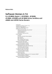
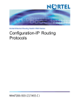
In this scenario (Figure 1):
■
Three users need to receive and make phone calls through a firewall. An
AR750S router is the firewall.
■
The router’s interface to the public Internet is eth1.
■
The router’s interface to the private LAN is vlan1. Each user is directly
plugged into one of the router’s LAN switch ports.
Important: This example uses 10.10.10.10 instead of a globally-unique IP
address on the firewall's public interface. Replace this address with a suitable
global address for your network.
This example only describes the configuration of the firewall to allow traffic to
and from residential gateways and phones. You may also need to configure
firewall rules for other devices in the LAN, such as servers and PCs.
Software Version 2.7.4
C613-10444-00 REV A
8
VoIP Phone Calls and the Firewall
Release Note
Figure 1: Configuration for allowing VoIP traffic through the firewall
SIP proxy server
Internet
public: eth1
private: vlan1
10.10.10.10
192.168.1.100
RG613
RG613
RG613
residential
gateway
residential
gateway
residential
gateway
192.168.1.1
192.168.1.2
192.168.1.3
fw-sip-config
Software Version 2.7.4
C613-10444-00 REV A
Software Version 2.7.4
# Allowing VoIP phone calls through the firewall
# IP and firewall configuration
# Configure IP on eth1 public interface
# Note: Replace 10.10.10.10 in this example with your globally-unique IP address
enable ip
add ip interface=eth1 ip=10.10.10.10
add ip route=0.0.0.0 mask=0.0.0.0 interface=eth1 next=ip-address-of-your-isp
# Configure IP on vlan1 private interface
add ip interface=vlan1 ip=192.168.1.100 mask=255.255.255.0
# Enable the firewall and the SIP ALG
enable firewall
enable firewall sipalg
# Create a firewall policy and add the interfaces to it
create firewall policy=voip
add firewall policy=voip interface=eth1 type=public
add firewall policy=voip interface=vlan1 type=private
# Configure NAPT by using firewall rules on public interface
# Note: Enter each command into the router on a single line
add firewall policy=voip rule=11 interface=eth1 protocol=udp action=nat nattype=napt
ip=192.168.1.1 gblip=10.10.10.10 port=5060 gblport=61001
add firewall policy=voip rule=12 interface=eth1 protocol=udp action=nat nattype=napt
ip=192.168.1.2 gblip=10.10.10.10 port=5060 gblport=61002
add firewall policy=voip rule=13 interface=eth1 protocol=udp action=nat nattype=napt
ip=192.168.1.3 gblip=10.10.10.10 port=5060 gblport=61003
# Configure NAPT by using firewall rules on private interface
# Note: Enter each command into the router on a single line
add firewall policy=voip rule=1 interface=vlan1 protocol=udp action=nat nattype=napt
ip=192.168.1.1 gblip=10.10.10.10 port=5060 gblport=61001
add firewall policy=voip rule=2 interface=vlan1 protocol=udp action=nat nattype=napt
ip=192.168.1.2 gblip=10.10.10.10 port=5060 gblport=61002
add firewall policy=voip rule=3 interface=vlan1 protocol=udp action=nat nattype=napt
ip=192.168.1.3 gblip=10.10.10.10 port=5060 gblport=61003
Software Version 2.7.4
C613-10444-00 REV A
9
10
VoIP Phone Calls and the Firewall
Release Note
New and Modified Commands
The following commands are new in Software Version 2.7.4:
■
enable firewall sipalg
■
disable firewall sipalg
The following commands include new features in Software Version 2.7.4:
■
add firewall policy rule
■
enable firewall policy debug
■
disable firewall policy debug
New parameter options are shown in bold in the command syntax.
The following show commands include new information in Software Version
2.7.4:
■
show firewall
■
show firewall policy
New entries are shown in bold in the example output.
enable firewall sipalg
Syntax
Description
ENAble FIREwall SIPAlg
This command enables the Session Initiation Protocol (SIP) Application Layer
Gateway (ALG). The SIP ALG allows SIP to set up sessions through the
firewall, when used in combination with NAPT firewall policy rules to modify
SIP packets. The SIP ALG is disabled by default.
disable firewall sipalg
Syntax
Description
DISable FIREwall SIPAlg
This command disables the Session Initiation Protocol (SIP) Application Layer
Gateway (ALG). The SIP ALG is disabled by default.
Software Version 2.7.4
C613-10444-00 REV A
Software Version 2.7.4
11
add firewall policy rule
Syntax
Description of changes
ADD FIREwall POLIcy=policy-name RUle=rule-id
ACtion={ALLOw|DENY|NAT|NONat} INTerface=interface
PROTocol={protocol|ALL|EGP|GRE|ICmp|OSPF|SA|TCP|UDP}
[AFTer=hh:mm] [BEFore=hh:mm]
[DAYs={MON|TUE|WED|THU|FRI|SAT|SUN|WEEKDAY|
WEEKEND}[,...]] [ENCapsulation={NONE|IPSec}]
[GBLIP=ipadd] [GBLPort={ALL|port[-port]|service-name}]
[GBLRemoteip=ipadd[-ipadd]] [IP=ipadd[-ipadd]]
[LISt={list-name|RADius}]
[NATType={DOuble|ENHanced|NApt|REVerse|STAndard}]
[NATMask=ipadd] [POrt={ALL|port[-port]|service-name}]
[REMoteip=ipadd[-ipadd]] [SOurceport={ALL|port[-port]}]
[TTL=hh:mm]
With Software Version 2.7.4 you can add up to 1200 rules to each firewall
policy.
A new option, napt, has been added to the nattype parameter. The nattype
parameter may only be used when action=nat. NAPT translates the address
and port of packets sent to and from private side devices. Therefore it
translates source address and port for outbound traffic and destination address
and port for inbound traffic (see Table 4 on page 6). The private side address
and port are specified with the ip and port parameters. The public side address
and port are specified with the gblip and gblport parameters.
enable firewall policy debug
Syntax
Description of changes
ENAble FIREwall POLIcy[=policy-name]
DEBug={ALL|ARP|HTTP|PACKET|PKT|PROCESS|PROXY|SMTP|
RADius|TCP|UPNP|ERRORcode|MESSage|PARSing|SIPAlg|TRAce}
This command enables the display of information that may help with
diagnosing and fixing firewall behaviour. New debugging modes have been
added for the SIP ALG. Debugging is disabled by default.
Table 5: New debugging options for SIP ALG
Software Version 2.7.4
C613-10444-00 REV A
Option
Result
ERRORcode
Translates internal SIP ALG error codes into meaningful messages,
displaying any errors encountered during processing.
MESSage
Translates each SIP message that is passed to the SIP ALG and displays its
contents line by line. The contents of a SIP message include a SIP header
and may include a Session Description Protocol (SDP) message body. Each
message is displayed first in its unmodified state as it arrives for
processing by the SIP ALG, then in its modified state after processing.
PARSing
Displays the steps the firewall takes during the parsing of a SIP message
(header and body) while they are occurring. This includes showing how
the message is modified to facilitate communication across the firewall.
SIPalg
Enables errorcode, message, and parsing debugging.
TRAce
Displays the names of all the functions that the SIP ALG calls when it
processes a SIP message
12
VoIP Phone Calls and the Firewall
Release Note
disable firewall policy debug
Syntax
Description of changes
DISable FIREwall POLIcy[=policy-name]
DEBug={ALL|ARP|HTTP|PACKET|PKT|PROCESS|PROXY|SMTP|
RADius|TCP|UPNP|ERRORcode|MESSage|PARSing|SIPAlg|TRAce}
This command disables firewall debugging, including the new debugging
options for SIP ALG. Debugging is disabled by default.
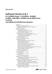
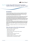
show firewall
Syntax
Description of changes
SHow FIREwall
Output from this command now indicates whether the SIP ALG is enabled or
disabled.
Figure 2: Example output from the show firewall command
Firewall Configuration
Status .................... enabled
Enabled Notify Options .... manager
SIP ALG enabled ........... TRUE
Maximum Packet Fragments .. 20
Policy : voip
TCP Timeout (s) ...................
UDP Timeout (s) ...................
Other Timeout (s) .................
TCP Handshake Timeout Mode ........
SMTP Domain .......................
TCP Setup Proxy ...................
UPNP ..............................
WAN interfaces ..................
LAN interfaces ..................
Maximum port maps ...............
SIP ALG ...........................
Private Interface : eth1-1
Private Interface : eth1-2
Public Interface : eth0-0
Method ..........................
3600
1200
1200
Normal
not set
enabled
disabled
none
none
250
enabled
dynamic
Software Version 2.7.4
C613-10444-00 REV A
Software Version 2.7.4
13
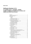
show firewall policy
Syntax
Description of changes
SHow FIREwall POLIcy[=policy-name] [COUnter] [DYnamic]
[LISt] [SUMmary] [USer]
When you specify a policy using the policy parameter, output from this
command now indicates:
■
whether the SIP ALG is enabled or disabled
■
if one of the new debugging options is enabled on the policy
■
if any rules on the policy use NAPT
If you specify the counter parameter, the output also includes the following
entries:
■
Total number of SIP messages
The number of SIP messages this policy has processed since the router last
started up.
■
Number of SIP messages ignored
The number of SIP messages that were passed to the SIP ALG but ignored
because the SIP message type defined in the SIP message header was
unknown (not supported).
■
Number of audio sessions created
The number of VoIP sessions that were created as a result of a successful SIP
peer-to-peer negotiation, since the router last started up.
Figure 3: Example output from the show firewall policy=voip command
Policy : voip
TCP Timeout (s) ...................
UDP Timeout (s) ...................
Other Timeout (s) .................
TCP Handshake Timeout Mode ........
MAC Cache Timeout (m) .............
RADIUS Limit ......................
Accounting ........................
Enabled Logging Options ...........
Enabled Debug Options .............
Identification Protocol Proxy .....
Enabled IP options ................
Enhanced Fragment Handling ........
Enabled ICMP forwarding ...........
Receive of ICMP PINGS .............
Number of Notifications ...........
Number of Deny Events .............
Number of Allow Events ............
Number of Active TCP Opens ........
Number of Active Sessions .........
Cache Hits ........................
Discarded ICMP Packets ............
SMTP Domain .......................
TCP Setup Proxy ...................
UPNP ..............................
WAN interfaces ..................
LAN interfaces ..................
Maximum port maps ...............
SIP ALG ...........................
Software Version 2.7.4
C613-10444-00 REV A
3600
1200
1200
Normal
1440
100
disabled
none
errorcode,parsing
enabled
none
none
none
enabled
0
1
0
0
0
0
0
not set
enabled
disabled
none
none
250
enabled
14
VoIP Phone Calls and the Firewall
Release Note
Figure 3: Example output from the show firewall policy=voip command (cont.)
Private Interface : eth0
Trust Private ...................
Rule ............................
Action ........................
NAT type ......................
IP ............................
Protocol ......................
Port ..........................
Global IP .....................
Global Port ...................
Source Port ...................
Days ..........................
Public Interface : eth1
Method ..........................
Rule ............................
Action ........................
NAT type ......................
IP ............................
Protocol ......................
Port ..........................
Global IP .....................
Global Port ...................
Source Port ...................
Days ..........................
yes
3
nat
napt
192.168.10.1
UDP
5060
10.10.10.10
61001
all
all
4
nat
napt
192.168.10.2
UDP
5060
10.10.10.10
61002
all
all
dynamic
1
nat
napt
192.168.10.1
UDP
5060
10.10.10.10
61001
all
all
2
nat
napt
192.168.10.2
UDP
5060
10.10.10.10
61002
all
all
Software Version 2.7.4
C613-10444-00 REV A
Software Version 2.7.4
15
VLAN Tagging on Multiple Logical
Ethernet Interfaces
Software Version 2.7.4 enables you to create up to 600 VLAN tagged logical
interfaces on each Eth interface, and give them a VLAN priority.
Configuration
To create a VLAN tagged eth interface and give it a VLAN priority, use the
command:
add ip interface=eth-interface ipaddress={ipadd|dhcp}
[vlantag={1..4094|none}] [vlanpriority=0..7]
[other-options...]
Example
To create two logical interfaces on the eth0 interface, tag them with different
VLAN tags, and give traffic on one a higher priority, use the commands:
add ip interface=eth0-0 ipaddress=192.168.1.1 vlantag=2
vlanpriority=2
add ip interface=eth0-1 ipaddress=192.168.2.1 vlantag=3
vlanpriority=3
You could use these two interfaces to separate and prioritise traffic destined for
two different users.
Modified Commands
add ip interface
set ip interface
Syntax
Software Version 2.7.4
C613-10444-00 REV A
ADD IP INTerface=interface IPaddress={ipadd|DHCP}
[ADVertise={YES|NO}] [BROadcast={0|1}]
[DIRectedbroadcast={False|NO|OFF|ON|True|YES}]
[FILter={0..99|NONE}] [FRAgment={NO|OFF|ON|YES}]
[GRAtuitousarp={ON|OFF}] [GRE={0..100|NONE}]
[IGMPProxy={OFF|UPstream|DOWNstream}]
[INVersearp={ON|OFF}] [MASK=ipadd] [METric=1..16]
[MULticast={BOTH|NO|OFF|ON|RECeive|SENd|YES}]
[OSPFmetric=1..65534] [POLicyfilter={100..199|NONE}]
[PREferencelevel={-2147483648..2147483647|NOTDEFAULT}]
[PRIorityfilter={200..299|NONE}]
[[PROxyarp={False|NO|OFF|ON|True|YES|STrict|DEFRoute}]
[RIPMetric=1..16]
[SAMode={Block|Passthrough}]
[VJC={False|NO|OFF|ON|True|YES}]
[VLANPRiority=0..7|None] [VLantag={1..4094|None}]
16
VLAN Tagging on Multiple Logical Ethernet Interfaces
Release Note
SET IP INTerface=interface [ADVertise={YES|NO}]
[PREferencelevel={-2147483648..2147483647|NOTDEFAULT}]
[BROadcast={0|1}]
[DIRectedbroadcast={False|NO|OFF|ON|True|YES}]
[FILter={0..99|NONE}] [FRAgment={NO|OFF|ON|YES}]
[GRAtuitousarp={ON|OFF}] [GRE={0..100|NONE}]
[IGMPProxy={OFF|UPstream|DOWNstream}]
[INVersearp={ON|OFF}] [IPaddress=ipadd|DHCP]
[MASK=ipadd] [METric=1..16]
[MULticast={BOTH|OFF|ON|RECeive|SENd}]
[OSPFmetric=1..65534|DEFAULT]
[POLicyfilter={100..199|NONE}]
[PRIorityfilter={200..299|NONE}]
[PROxyarp={False|NO|OFF|ON|True|YES|STrict|DEFRoute}]
[RIPMetric=1..16] [SAMode={Block|Passthrough}]
[VJC={False|NO|OFF|ON|True|YES}]
[VLANPRiority=0..7|None] [VLantag={1..4094|None}]
Description of changes
The new vlanpriority parameter specifies the value of the 802.1p User Priority
field of the VLAN tag. This priority is written into all VLAN-tagged frames
sent out the interface. Downstream routers may use this priority to determine
the quality of service the frame receives. This parameter is only valid when
vlantag is specified. The default is none when vlantag=none, and 0 when
vlantag specifies a value.
The pre-existing vlantag parameter specifies the VID (VLAN Identifier) to be
included in the header of each frame that is transmitted over the logical
interface. This parameter is valid for Eth interfaces only. Multiple logical
interfaces on the same physical interface can share the same VLAN tag. The
default is none, which means no VID is included.
show ip interface
Syntax
Description of changes
SHow IP INTerface[=interface] [COUnter[=MULticast]]
Output of this command now includes the VLAN priority for Ethernet frames
sent out over the interface.
Figure 4: Example output from the show ip interface command
Interface
Type
IP Address
Bc Fr PArp Filt RIP Met.
SAMode IPSc
Pri. Filt
Pol.Filt Network Mask
MTU
VJC
GRE OSPF Met. DBcast Mul.
VLAN Tag
VLAN Priority
InvArp
-------------------------------------------------------------------------------LOCAL
--Not set
- - --- -Pass
-----Not set
1500 --- -----none
none
eth0-1
Static
192.168.2.1
1 n On
--- 01
Pass
No
----255.255.255.0
1500 --- 0000000001 No
Rec
1
2
eth0-2
Static
192.168.3.1
1 n On
--- 01
Pass
No
----255.255.255.0
1500 --- 0000000001 No
Rec
2
0
---------------------------------------------------------------------------------
Software Version 2.7.4
C613-10444-00 REV A
Software Version 2.7.4
17
Link Discovery Protocol
This enhancement enables the router or switch to receive and process Cisco®
Discovery Protocol packets. This enables management of certain Cisco devices.
The Cisco Discovery Protocol is a link layer protocol used by Cisco devices to
advertise their network layer addresses, device type and capabilities. Cisco
devices regularly sent out advertisements. With this enhancement, the router
or switch can read, check, and process these advertisements.
Parts of the Cisco CDP MIB (CISCO-CDP-MIB.mib) have also been
implemented. The router or switch can:
■
read all CDP MIB variables that relate to reception of CDP advertisements
■
write the variables cdpInterfaceEnable and cdpGlobalRun.
You can create triggers to activate scripts when the CDP discovers a new device
and when the CDP removes a device through the action of the holddown timer.
New Commands: CDP
disable lldp cdp
Syntax
DISable LLDP CDP
disable lldp cdp debug
Syntax
DISable LLDP CDP DEBug[={PACket|ADJacency|EVent}]
disable lldp cdp interface
Syntax
DISable LLDP CDP INTerface=interface
enable lldp cdp
Syntax
ENAble LLDP CDP
enable lldp cdp debug
Syntax
Software Version 2.7.4
C613-10444-00 REV A
ENAble LLDP CDP DEBug[={PACket|ADJacency|EVent}]
18
Link Discovery Protocol
Release Note
enable lldp cdp interface
Syntax
ENAble LLDP CDP INTerface=interface
where interface is one of:
■
ethn
An Eth port, where n is the Eth port instance (for example, eth0)
■
portm
A switch port, where m is the port number (for example, port2 for the switch
port numbered 2).
reset lldp cdp counters
Syntax
RESET LLDP CDP COUnters
reset lldp cdp table
Syntax
RESET LLDP CDP TAble
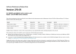
show lldp cdp
Syntax
SHow LLDP CDP
Figure 5: Example output from the show lldp cdp command
CDP general information
--------------------------------------------Enabled ...................... Yes
Number of CDP neighbours ..... 14
SysUpTime .................... 12345.42s
CDP processing time .......... 3.385727s
Triggers:
CDP neighbour add .......... CDP neighbour remove ....... 5
---------------------------------------------
Software Version 2.7.4
C613-10444-00 REV A
Software Version 2.7.4
19
show lldp cdp entry
Syntax
SHow LLDP CDP ENTry=entryname [PROTocol] [VERsion]
This command displays information about a neighbour or neighbours.
The entry parameter specifies the name of the neighbour you want information
for. The string can be any format and can be terminated with a wild-card
character (*) to match more than one device. The wild-card character can be
entered on its own to match all neighbours.
Figure 6: Example output from the show lldp cdp entry command
CDP entry information
-------------------------------------------------------------------------------Device ID ................. Switch
Protocol information:
IP address ................ 192.168.1.202
Platform .................... cisco WS-C3750G-24TS
Capabilities ................ Router,Switch,IGMP device
Interface ................... port20
Port ID (outgoing port) ..... GigabitEthernet1/0/10
Holdtime .................... 155s
Version:
Cisco Internetwork Operating System Software
IOS (tm) C3750 Software (C3750-I5-M), Version 12.2(20)SE, RELEASE SOFTWARE (fc1)
Copyright (c) 1986-2004 by cisco Systems, Inc.
Compiled Wed 19-May-04 11:52 by yenanh
--------------------------------------------------------------------------------
show lldp cdp interface
Syntax
SHow LLDP CDP INTerface[=interface]
Figure 7: Example output from the show lldp cdp interface command
CDP interface information
------------------------Name
Status
------------------------port1
Down
port2
Up
port3
Down
port8
Up
port14
Down
port16
Up
-------------------------
Software Version 2.7.4
C613-10444-00 REV A
20
Link Discovery Protocol
Release Note
show lldp cdp neighbour
Syntax
SHow LLDP CDP NEIghbour [INTerface=interface] [DETail]
Figure 8: Example output from the show lldp cdp neighbour command
CDP neighbour information
------------------------------------------------------------------------------Device ID
Loc Int
Hold Capability Platform
Port ID
------------------------------------------------------------------------------Switch
port20
165s RSI
WS-C3750G-24TS
Gig 1/0/10
-------------------------------------------------------------------------------
Figure 9: Example output from the show lldp cdp neighbour detail command
CDP neighbour information
------------------------------------------------------------------------------Device ID ................. Switch
Protocol information:
IP address ................ 192.168.1.202
Platform .................... cisco WS-C3750G-24TS
Capabilities ................ Router,Switch,IGMP device
Interface ................... port20
Port ID (outgoing port) ..... GigabitEthernet1/0/10
Holdtime .................... 177s
Version:
Cisco Internetwork Operating System Software
IOS (tm) C3750 Software (C3750-I5-M), Version 12.2(20)SE, RELEASE SOFTWARE (fc1)
Copyright (c) 1986-2004 by cisco Systems, Inc.
Compiled Wed 19-May-04 11:52 by yenanh
-------------------------------------------------------------------------------
show lldp cdp counters
Syntax
SHow LLDP CDP COUnters
Figure 10: Example output from the show lldp cdp counters command
CDP traffic counters
----------------------------------Rx CDPv1 packets ....... 0
Rx CDPv2 packets ....... 1188
Rx total packets ....... 1188
Errors:
Header syntax ........ 0
Checksum error ....... 0
No memory ............ 0
Invalid .............. 0
Fragments ............ 0
-----------------------------------
Software Version 2.7.4
C613-10444-00 REV A
Software Version 2.7.4
21
Modified Command: Triggers
create trigger
Syntax
CREATE TRIGger=trigger-id MODule=LLDP
EVENT={CDPAdd|CDPRemove}
[AFTer=hh:mm] [BEFore=hh:mm]
[{DAte=date|DAYs=day-list}] [NAMe=name]
[REPeat={Yes|No|ONCe|FORever|count}]
[SCript=filename...] [STAte={ENAbled|DIsabled}]
[TEST={YES|NO|ON|OFF|True|False}]
If you specify event=cdpadd, the trigger activates a script when the CDP
discovers a new device.
If you specify event=cdpremove, the trigger activates a script when the CDP
removes a device through the action of the holddown timer.
WAN Load Balancing
With the increasing use of the Internet to service core business functions comes
the need for reliable WAN connectivity. A specific aspect of this requirement is
for reliable connectivity to particular destinations. A simple and effective
method of achieving this is to provide alternative network connections via
different Internet Service Providers (ISPs).
WAN load balancing enables efficient use of multiple WAN connections. When
a router simultaneously connects to multiple WAN networks, the WAN load
balancer will try to distribute the router traffic equally across each network
interface.
For detailed information and commands, see the WAN Load Balancing chapter
of your router’s Software Reference for Software Release 2.7.3.
Software Version 2.7.4
C613-10444-00 REV A
22
Inactivity Timeout
Release Note
Inactivity Timeout
This enhancement enables you to set inactivity timeout periods on:
■
telnet and other TTY connections, by using the command set tty
■
console connections over an ASYN port, by using the command set asyn.
When the idle timer expires for an ASYN connection, the user is logged out
and the connection displays the login prompt. When the idle timer expires for a
telnet connection, the user is logged out and the connection is terminated.
Modified Commands
set tty
Syntax
SET TTy [IDLEtimeout={10..4294967294|OFF|0}]
[other-options...]
Timeout units are seconds. If the timeout value is off or zero, telnet sessions
never time out. The default is off.
show tty
Syntax
SHow TTy[=tty-number|ALL]
Figure 11: Example output from the show tty command
TTY information
Instance ..................
Login name ................
Description ...............
Secure ....................
Connections to ............
Current connection ........
In flow state .............
Out flow state ............
Attached module ...........
Attached module instance ..
Type ......................
Prompt ....................
Echo ......................
Attention .................
Manager ...................
Edit mode .................
History length ............
Page mode/length ..........
Idle Timeout (seconds).....
30
manager
Telnet 1
yes
21
0
on
on
Telnet
1
VT100
default
yes
char
yes
insert
30
22
300
Figure 12: Example output from the show tty=all summary command
TTY Description User name Module Inst Mgr Timeout
---------------------------------------------------------016 Port 0
support
TSER
000 yes off
018 Telnet 1
manager
TELN
001 yes 300
----------------------------------------------------------
Software Version 2.7.4
C613-10444-00 REV A
Software Version 2.7.4
23
set asyn
Syntax
SET ASYn[=asyn-number]
[IDLEtimeout={10..4294967294|OFF|0}] [other-options...]
Timeout units are seconds. An asynchronous port with a value of off or zero
never times out. The default is off.
show asyn
Syntax
SHow ASYn[=asyn-number|ALL]
Figure 13: Example output from the show asyn command
ASYN 2:0000070953 seconds Last change at:0000009023 seconds
ASYN information
Name ...................... Asyn 0
Status .................... enabled
Mode ...................... PPP
PPP Index ................. 1
TX ACCM ................... 00000000
Data rate ................. 38400
Parity .................... none
Data bits ................. 8
Stop bits ................. 1
Test mode ................. no
In flow state (mode) ...... on (Hardware)
Out flow state (mode) ..... off (Hardware)
Autobaud mode ............. disabled
Max tx queue length ....... 100
TX queue length ........... 0
Transmit frame ............ none
RX queue length ........... 0
IP address ................ none
Max transmission unit ..... 1500
IPX Network ............... none
Control signals
DTR (out) ............... on on 1
RTS (out) ............... on - 1
CD (in) ............... off connect 0
CTS (in) ............... off - 0
RNG (in) ............... off - 0
TTY information
Instance ..................
Login Name ................
Description ...............
Secure ....................
Connections to ............
Current connection ........
In flow state .............
Out flow state ............
Type ......................
Prompt ....................
Echo ......................
Attention .................
Manager ...................
Edit mode .................
History length ............
Page size .................
Idle Timeout (seconds).....
Software Version 2.7.4
C613-10444-00 REV A
18
Asyn 2
yes
none
on
on
VT100
login
yes
break
no
insert
20
22
300
24
Summer Time
Release Note
Summer Time
This enhancement enables you to:
■
define a timezone
■
enable summer time (daylight saving time) and specify when summer time
starts and ends.
Once summer time is enabled, the local time automatically changes when
summer time begins and ends.
You still need to set the local time by using the command:
set time
If you set the time before configuring summer time, set the time to standard
time even if summer time currently applies. When you configure summer time
the router or switch will automatically change the time to show summer time if
necessary.
If you set the time after configuring summer time, set the time to the current
local time: either summer time or standard time, whichever currently applies.
New Commands: Timezone
clear timezone
Syntax
CLear TIMEZone
This command removes the timezone definition from the system, which is
equivalent to setting a timezone of UTC±00:00.
set timezone
Syntax
SET TIMEZone[=timezone-name] [UTCoffset=std-utc-offset]
where:
■
timezone-name is a character string from 1 to 7 characters in length
representing the timezone abbreviation for standard time for this timezone
■
std-utc-offset is the amount of time by which this timezone is offset from
UTC time during standard time (not summer time). Time is a positive or
negative number in the format hh[:mm[:ss]], where hh=0-23, mm=0-59 and
ss=0-59. If hours are specified then minutes and seconds are optional. If
minutes are specified then seconds are optional.
This command supersedes the command set utc offset.
Software Version 2.7.4
C613-10444-00 REV A
Software Version 2.7.4
25
show timezone
Syntax
SHow TIMEZone
Figure 14: Example output from the show timezone command
Timezone name is set to 'NZST', offset from UTC is +12:00
New Commands: Summertime
clear summertime
Syntax
CLear SUMMertime
This command returns the summer time settings to default values (see
set summertime below)
disable summertime
Syntax
DISable SUMMertime
enable summertime
Syntax
Software Version 2.7.4
C613-10444-00 REV A
ENAble SUMMertime
26
Summer Time
Release Note
set summertime
Syntax
SET SUMMertime[=summertime-zone-name]
[STARTDAte=date]
[STARTMonth=month STARTWeek=week STARTDay=day]
[STARTTime=time]
[ENDDAte=date]
[ENDMonth=month ENDWeek=week ENDDay=day]
[ENDTime=time]
[Offset=offset]
where:
■
summertime-zone-name is a character string from 1 to 7 characters in length.
■
date is the date in d-mmm-yyyy, dd-mmm-yyyy, d-mmm-yy or dd-mm-yy
format. The day is one or two digits, the month is the first three letters of
the month (for example, apr), and the year is two or four digits.
■
month is the name of the month. The name is the first three letters of the
month (for example, apr).
■
week is a number between 1 and 5. 1 represents the first week of the month
and 5 represents the last week of month.
■
day is the first three letters of the name of a day of the week (for example,
mon, tue, wed).
■
time is the time in hh[:mm[:ss]] format, where hh=0-23, mm=0-59 and
ss=0-59. If hours are specified then minutes and seconds are optional. If
minutes are specified then seconds are optional.
■
offset is the number of minutes the time changes by, in the range 0 to 120.
Default values are:
summertime=dst
startmonth=apr startweek=1 startday=sun starttime=02:00
endmonth=oct endweek=5 endday=sun endtime=02:00
offset=60
show summertime
Syntax
SHow SUMMertime
Figure 15: Example output from the show summertime command
Summertime configuration
-------------------------------------------------------------------------------Enabled ........... No
Summertime name ... DST
Start ............. Sunday 02-Apr-2006 02:00am
End ............... Sunday 30-Oct-2005 02:00am
Offset ............ 60 minutes
Start rule ........ Recurring, First Sunday in April at 02:00am
End rule .......... Recurring, Last Sunday in October at 02:00am
--------------------------------------------------------------------------------
Software Version 2.7.4
C613-10444-00 REV A
Software Version 2.7.4
27
Displaying and Disabling All Active
Debugging
This enhancement provides an easy way to:
■
see which protocols currently have debugging enabled
■
disable debugging for all these protocols at once.
New and Modified Commands
show debug active
Syntax
SHow DEBug [ACTive={ALL|module}]
where module is the name of a switch or router module from the following list:
BGP, INTERFACE, IP, LACP, MSTP, OSPF, PIM, RADIUS, STP, SWITCH,
TACACS, TACPLUS or VRRP.
The output only shows the modules from this list that have debugging
enabled. It does not list modules:
■
for which debugging is disabled
■
which are not in the list, even if debugging is enabled for them
Figure 16: Example output from the show debug active command
Active Debug
BGP:
Debug Types
Peer IP Address
------------------------------------msg
state
192.168.1.20
-------------------------------------
DHCP: (no options available)
IP IGMP:
Destination IP Address
Source IP Address
------------------------------------------224.1.2.3
10.10.10.1
192.168.1.20
192.168.2.20
------------------------------------------LOAD BALANCER:
Debug Types Enabled:
http
firewall
trace
Software Version 2.7.4
C613-10444-00 REV A
28
Displaying and Disabling All Active Debugging
Release Note
disable debug active
Syntax
DISABLE DEBug ACTive={ALL|module}
where module is the name of a switch or router module from the following list:
BGP, INTERFACE, IP, LACP, MSTP, OSPF, PIM, RADIUS, STP, SWITCH,
TACACS, TACPLUS or VRRP.
Software Version 2.7.4
C613-10444-00 REV A
Software Version 2.7.4
29
Graphical User Interface (GUI) for AT-9900
Series Switches
The GUI (Graphical User Interface) is a web-based device management tool,
designed to make it easier to configure and monitor the router or switch. The
GUI provides an alternative to the CLI (Command Line Interface). Its purpose
is to make complicated tasks simpler and regularly-performed tasks quicker.
See Using the Graphical User Interface (GUI) at the end of this Release Note
for:
■
browser settings
■
details of how to access the switch via the GUI
■
an overview of the GUI’s features and navigation
The GUI is stored on the router or switch in the form of an embedded resource
file, d9924e22.rsc. Resource files are model-specific, with the model and
version encoded in the file name.
Using GUI Help
Help button
The GUI’s context-sensitive help system is displayed in a pop-up window that
covers the title of the GUI page. You can move the banner to any part of your
screen and/or resize it. To display help, click the Help button above the sidebar
menu or on the page for which you require assistance. The following types of
help are available:
■
Click General Page Info for brief information about background and
process flow. This page is also displayed when you click the Help button.
■
Click Page Element Info and roll your mouse over an element to view
information about that element.
To freeze the banner so that the help displayed does not change when you
move the mouse, press the Ctrl key. To unfreeze, press the Ctrl key again.
Note that element information is not available for most entries in tables. To
see descriptions of table columns, click Complete Help Page.
■
Click Complete Help Page to see all available information in a separate
printable window, including information about elements.
Saving Configurations Entered with the GUI
Save button
Configuration changes applied using the GUI can be saved as a configuration
file by clicking the Save button at the top of the sidebar menu. A pop-up Save
window gives you the option of saving to the current configuration file, to
another existing file, or to a new file. You can also choose to use this
configuration when the router or switch restarts.
When the Save button is red, this indicates that changes have been made to the
configuration and not yet saved. If you attempt to exit the GUI without saving
the configuration, a pop-up window lets you choose whether or not to save it.
The configuration file you create with the GUI Save function records
passwords in encrypted form, not plaintext.
Software Version 2.7.4
C613-10444-00 REV A
30
Enhancements to Virtual Bridge (VLAN) MIB Support
Release Note
Enhancements to Virtual Bridge (VLAN)
MIB Support
RFC 2674, Definitions of Managed Objects for Bridges with Traffic Classes, Multicast
Filtering and Virtual LAN Extensions, defines a portion of the Management
Information Base (MIB) for managing IEEE Standard 802.1Q VLANs.
Objects defined in this MIB reside in the mib(1) sub-tree, under the dot1dBridge
sub-tree defined in RFC 1493, and have the object identifier qBridgeMIBObjects
({ mib-2 dot1dBridge(17) qBridgeMIB(7) 1 }).
Previous software versions supported the following objects and groups in
the MIB:
■
All objects in the dot1qBase Group.
■
The dot1qVlanNumDeletes object in the dot1qVlan Group.
■
The dot1qVlanCurrentTable object in the dot1qVlan Group.
■
The dot1qVlanStaticTable object in the dot1qVlan Group.
■
The dot1qNextFreeLocalVlanIndex object in the dot1qVlan Group.
■
The dot1qPortVlanTable object in the dot1qVlan Group.
Software Version 2.7.4 adds support for the dot1qFdbTable and dot1qTpFdbTable
tables, and modifies the use of the dot1qVlanFdbId object in the
dot1qVlanCurrentEntry table.
dot1qFdbTable contains configuration and control information for each Filtering
Database currently operating on the device. dot1qFdbTable has an entry for each
configured VLAN, containing the following objects:
■
dot1qFdbId
The identity of this Filtering Database. Returns the VLAN ID.
■
dot1qFdbDynamicCount
The current number of dynamic entries in this Filtering Database. Returns
the number of MAC addresses used by the VLAN.
dot1qTpFdbTable contains information about unicast entries for which the
device has forwarding and/or filtering information. dot1qTpFdbTable has an
entry for each VLAN ID/MAC address pair, containing the following objects:
■
dot1qTpFdbAddress
A unicast MAC address for which the device has forwarding and/or
filtering information.
■
dot1qTpFdbPort
Either the value ‘0’, or the port number of the port on which a frame having
a source address equal to the value of the corresponding instance of
dot1qTpFdbAddress has been seen. Returns the same value as the equivalent
dot1dTpFdbPort object.
■
dot1qTpFdbStatus
The status of this entry; one of other(1), invalid(2), learned(3), self(4), or
mgmt(5). Returns the same value as the equivalent dot1dTpFdbStatus object.
Software Version 2.7.4
C613-10444-00 REV A
Software Version 2.7.4
31
RADIUS Accounting and 802.1x Dynamic
VLAN Assignment
The RADIUS server can now be configured to allow a user to be authenticated
in only one place at a time. This is achieved by limiting the number of open
RADIUS accounting sessions for a supplicant to one, and provides for greater
security.
Radius accounting is included for:
■
MAC based port authentication
■
802.1x port authentication in single-supplicant mode.
When a supplicant has been authenticated for a port, a START
Accounting-Request message is sent to the RADIUS server.
When a supplicant becomes unauthenticated, a STOP Accounting-Request
message is sent to the RADIUS server.
If no Accounting-Response is received from the RADIUS server after either a
START or STOP Accounting message is sent, (and once the RADIUS module
has reached its timeout and retry limit), the authorisation status of the
supplicant remains unaffected, but an appropriate message is logged.
Software Version 2.7.4
C613-10444-00 REV A
32
Enhancements to Login Authentication
Release Note
Enhancements to Login Authentication
This enhancement changes the approach that the router or switch uses for
authenticating users from RADIUS and the User Authentication Database.
Before Software Version 2.7.4, the router or switch searched the local user
database before attempting a RADIUS lookup. Software Version 2.7.4 enables
you to configure the router or switch to interrogate the RADIUS server first.
To do this, create users in the User Authentication Database of the new type
called “RADIUS unreachable” (RU) users, by using the command:
add user=login-name login={yes|no} password=password
radiusbackup=yes [other-options...]
If RU users are defined in the user database, the router or switch performs the
RADIUS lookup before checking the user database. If the lookup is successful,
the user is logged into the router or switch.
If the RADIUS server is unreachable, then the router or switch performs a user
database lookup for RU users only. Normal user database entries are not used
in this case.
If the RADIUS authentication fails, then the router or switch performs a lookup
in the user database, searching for normal (non-RU) users only.
Modified Commands
add user
Syntax
ADD USEr=login-name
LOgin={True|False|ON|OFf|Yes|No} PAssword=password
[RADiusbackup={ON|OFF|YES|NO|True|False}]
[other-options...]
set user
Syntax
SET USEr=login-name
[RADiusbackup={ON|OFF|YES|NO|True|False}]
[other-options...]
Software Version 2.7.4
C613-10444-00 REV A
Software Version 2.7.4
33
show user
Syntax
SHow USEr[=login-name]
Figure 17: Example output from the show user command
Number of logged in Security Officers currently active ...1
Number of Radius-backup users..... 2
User Authentication Database
-----------------------------------------------------------------------------Username: dave ()
Status: enabled
Privilege: Sec Off
Telnet: yes
Login: yes
RBU: yes
Callback number: 0061393546786
Calling number: 5554491
Logins: 2
Fails: 0
Sent: 0
Rcvd: 0
Authentications: 0 Fails: 0
Username: manager (Manager Account)
Status: enabled
Privilege: manager
Telnet: yes
Login: yes
RBU: no
Logins: 4
Fails: 0
Sent: 0
Rcvd: 0
Authentications: 0 Fails: 0
-----------------------------------------------------------------------------Active (logged in) Users
-----------------------User
Port/Device
Login Time
Location
--------------------------------------------------------------------manager
Asyn 0
14:33:22 18-Apr-2002
local
manager
Telnet 1
14:33:22 18-Apr-2002
10.1.1.1
---------------------------------------------------------------------
Software Version 2.7.4
C613-10444-00 REV A
34
Firewall: Using RADIUS to Authenticate MAC Addresses
Release Note
Firewall: Using RADIUS to Authenticate
MAC Addresses
This enhancement extends the firewall’s MAC address matching capabilities. It
enables the firewall to send queries about MAC addresses to a RADIUS server.
The response from the RADIUS server determines whether the packet is
allowed or denied.
The firewall stores the MAC address and RADIUS result in its MAC address
cache for a time length specified by using the command:
set firewall policy maccachetimeout=max-age
The default timeout is 1440 minutes (24 hours).
New and Modified Commands
add firewall policy rule
Syntax
ADD FIREwall POLIcy=policy-name RUle=rule-id
ACtion={ALLOw|DENY|NAT|NONat} INTerface=interface
PROTocol={protocol|ALL|EGP|GRE|ICmp|OSPF|SA|TCP|UDP}
[LISt={list-name|RADius|MACRADIUS}] [other-options...]
reset firewall policy maccache
Syntax
RESET FIREwall POLIcy=policy-name MACCACHE
set firewall policy
Syntax
SET FIREwall POLIcy=policy-name [MACCACHETIMEOUT=max-age]
[RADIUSLIMIT=number] [other-options...]
where
■
max-age is a time period from 1 to 43200 minutes.
■
number is a decimal value in the range 1 to 500.
Software Version 2.7.4
C613-10444-00 REV A
Software Version 2.7.4
35
show firewall policy
Syntax
SHow FIREwall POLIcy=policy-name [COUnter] [DYnamic]
[LISt] [SUMmary] [USer]
Figure 18: Example output from the show firewall policy command
Policy : admin
TCP Timeout(s).....................
UDP Timeout(s).....................
Other Timeout(s)...................
MAC Cache Timeout (m) .............
RADIUS Limit ......................
Accounting ........................
Enabled Logging Options ...........
Enabled Debug Options .............
Enhanced Fragment Handling ........
Enabled IP options ................
Enabled ICMP forwarding ...........
Receive of ICMP PINGS .............
Number of Notifications ...........
Number of Deny Events .............
Number of Allow Events ............
Number of Active TCP Opens ........
Number of Active Sessions .........
Cache Hits ........................
Discarded ICMP Packets ............
Spam Source Files .................
SMTP Domain .......................
HTTP Proxy Filter File ............
Cookies ...........................
TCP Setup Proxy ...................
UPNP ..............................
WAN interfaces ..................
LAN interfaces ..................
Maximum port maps ...............
Private Interface: eth0
Trust Private ...................
Public Interface: eth1
Method ..........................
Proxy ...........................
Private Interface .............
IP ............................
Direction .....................
Days ..........................
NAT .............................
Method ........................
Private Interface .............
Global IP .....................
Rule ............................
Action ........................
RADIUS MAC Lookup .............
IP ............................
Protocol ......................
Port ..........................
Global IP .....................
Global Port ...................
Source Port ...................
Days ..........................
Software Version 2.7.4
C613-10444-00 REV A
3600
1200
1200
1440
100
enabled
allow denydump
checksum
udp
none
ping timeexceeded
enabled
0
20
8987
0
1
429073
74
spam.spa
alliedtelesyn.co.nz
urlfilt.txt
enabled
enabled
enabled
eth0
vlan1
250
yes
dynamic
http
eth0
192.168.1.10
both
all
enhanced
enhanced interface
eth0
172.20.8.2
1
allow
enabled
192.168.1.2
TCP
23
0.0.0.0
23
all
all
36
Firewall: Using RADIUS to Authenticate MAC Addresses
Release Note
show firewall policy maccache
Syntax
SHow FIREwall POLIcy=policy-name MACCACHE
Figure 19: Example output from the show firewall policy maccache command
Policy : test - Cached MAC Addresses
MAC Address
Rule Type RADIUS Result Expiry (min) Cache Hits
------------------------------------------------------------------------------00-00-cd-0b-8c-84 Deny
Deny
205
16
00-00-cd-00-ab-dc Deny
Allow
996
400
00-0a-17-29-11-91 Allow
Allow
360
98
-------------------------------------------------------------------------------
Software Version 2.7.4
C613-10444-00 REV A
Software Version 2.7.4
37
Firewall: Automatic Teardown of Data
Connections
With this enhancement, the firewall can close a WAN link as soon as all TCP
connections are closed. This avoids the cost of unused dial-up links such as
ISDN links.
The firewall detects when TCP sessions are opened and closed. You can
configure triggers to activate when:
■
the first session opens, by specifying mode=start
■
the last TCP session closes, by specifying mode=end.
You can also see how many sessions are open.
Important This trigger only monitors TCP sessions, not UDP traffic or any
other traffic. Remember that the firewall may still be passing non-TCP traffic.
Modified Commands
create trigger
Syntax
CREate TRIGger=trigger-id
FIREwall={ALL|DOSattack|FRAgattack|HOStscan|PORtscan|
SESSION|SMTPATTACK|SMUrfattack|SYNattack|TCPattack}
[MODE={STArt|END|BOTH}] [AFTer=hh:mm] [BEFore=hh:mm]
[{DAte=date|DAYs=day-list}] [NAMe=name]
[REPeat={Yes|No|ONCe|FORever|count}]
[SCript=filename...] [STAte={ENAbled|DIsabled}]
[TEST={YES|NO|ON|OFF|True|False}]
set trigger
Syntax
Software Version 2.7.4
C613-10444-00 REV A
SET TRIGger=trigger-id
FIREwall={ALL|DOSattack|FRAgattack|HOStscan|PORtscan|
SESSION|SMTPATTACK|SMUrfattack|SYNattack|TCPattack}
[MODE={STArt|END|BOTH}] [AFTer=hh:mm] [BEFore=hh:mm]
[{DAte=date|DAYs=day-list}] [NAMe=name]
[REPeat={Yes|No|ONCe|FORever|count}]
[TEST={YES|NO|ON|OFF|True|False}]
38
Firewall: Automatic Teardown of Data Connections
Release Note
show trigger
Syntax
SHow TRIGger=trigger-id
Figure 20: Example output from the show trigger command
Trigger ..................... 1
Name ........................ Bring up Wellington link
Type and details ............ Time (13:45)
Days ........................ All
Active TCP sessions...........0
Enabled ..................... Enabled
Test ........................ No
Repeat ...................... No
Created/Modified ............ 1-Jun-2005 12:04:33
Number of Activations ....... 1
Last Activation ............. 14-Jun-2005 13:45:07
Number of scripts ........... 2
callwgtn.scp
idlewgtn.scp
Software Version 2.7.4
C613-10444-00 REV A
Software Version 2.7.4
39
OSPF: Route Filtering with Route Maps
This enhancement enables you to configure route maps to filter OSPF routes.
Route maps allow you to configure complex flexible filters. They achieve this
by having several levels of structure:
■
each route map consists of multiple entries
■
each entry consists of an action (include or exclude) and at least one clause:
•
zero or one match clauses, which determine which OSPF route attributes
match the entry. If you do not specify a match clause, every route
matches.
The match fields relevant for OSPF are interface, prefix list, next hop,
route source, metric, route type and tag.
•
zero or more set clauses, which change the attributes of matching
routes.
The set clauses relevant for OSPF are metric, type and tag.
You can use the route map in OSPF:
■
to filter OSPF routes before adding them to the IP route table for IP to use.
To do this, create the route map and use it in the command:
set ospf inroutemap=routemap-name
■
when redistributing static routes as OSPF AS external LSAs. See “OSPF:
Redistributing Static Routes” on page 46.
Modified Commands
For the add ip routemap and set ip routemap commands, this section only lists
the command syntax that is relevant for OSPF. Further options for BGP are
described in the Border Gateway Protocol version 4 (BGP-4) chapter of your
router or switch’s Software Reference.
add ip routemap
Syntax for
match clauses
ADD IP ROUTEMap=routemap ENTry=1..4294967295
[ACtion={INCLude|EXCLude}] MAtch
METRIC=0..4294967295[-0..4294967295]
ADD IP ROUTEMap=routemap ENTry=1..4294967295
[ACtion={INCLude|EXCLude}] MAtch INTERFACE=interface
ADD IP ROUTEMap=routemap ENTry=1..4294967295
[ACtion={INCLude|EXCLude}] MAtch
ROUTETYPE={INTRA|INTER|TYPE1|TYPE2|OTHER}
ADD IP ROUTEMap=routemap ENTry=1..4294967295
[ACtion={INCLude|EXCLude}] MAtch ROUTESOURCE=name
ADD IP ROUTEMap=routemap ENTry=1..4294967295
[ACtion={INCLude|EXCLude}] MAtch NEXThop=ipadd
Software Version 2.7.4
C613-10444-00 REV A
40
OSPF: Route Filtering with Route Maps
Release Note
ADD IP ROUTEMap=routemap ENTry=1..4294967295
[ACtion={INCLude|EXCLude}] MAtch PREFIXList=name
ADD IP ROUTEMap=routemap ENTry=1..4294967295
[ACtion={INCLude|EXCLude}] MAtch TAG=1..65535
Syntax for set clauses
ADD IP ROUTEMap=routemap ENTry=1..4294967295
[ACtion={INCLude|EXCLude}] SET METRIC=0..4294967295
ADD IP ROUTEMap=routemap ENTry=1..4294967295
[ACtion={INCLude|EXCLude}] SET TYPE={1|2}
ADD IP ROUTEMap=routemap ENTry=1..4294967295
[ACtion={INCLude|EXCLude}] SET TAG=1..65535
The routesource and prefixlist parameters use a pre-configured prefix list.
Prefix lists are already used by BGP and are described in the Border Gateway
Protocol version 4 (BGP-4) chapter of your router or switch’s Software
Reference.
delete ip routemap
Syntax
DELete IP ROUTEMap=routemap ENTry=1..4294967295
MAtch={ASPath|COMmunity|INTERFACE|MED|METRIC|NEXThop|
ORIGin|PREFIXList|ROUTESOURCE|ROUTETYPE|TAG}
DELete IP ROUTEMap=routemap ENTry=1..4294967295
SET={ASPath|BGPDampid|COMmunity|LOCalpref|MED|METric|
ORIGin|TAG|TYPE}
set ip routemap
Syntax for
match clauses
SET IP ROUTEMap=routemap ENTry=1..4294967295
[ACtion={INCLude|EXCLude}] MAtch
METRIC=0..4294967295[-0..4294967295]
SET IP ROUTEMap=routemap ENTry=1..4294967295
[ACtion={INCLude|EXCLude}] MAtch INTERFACE=interface
SET IP ROUTEMap=routemap ENTry=1..4294967295
[ACtion={INCLude|EXCLude}] MAtch
ROUTETYPE={INTRA|INTER|TYPE1|TYPE2|OTHER}
SET IP ROUTEMap=routemap ENTry=1..4294967295
[ACtion={INCLude|EXCLude}] MAtch ROUTESOURCE=name
SET IP ROUTEMap=routemap ENTry=1..4294967295
[ACtion={INCLude|EXCLude}] MAtch NEXThop=ipadd
SET IP ROUTEMap=routemap ENTry=1..4294967295
[ACtion={INCLude|EXCLude}] MAtch PREFIXList=name
SET IP ROUTEMap=routemap ENTry=1..4294967295
[ACtion={INCLude|EXCLude}] MAtch TAG=1..65535
Software Version 2.7.4
C613-10444-00 REV A
Software Version 2.7.4
Syntax for set clauses
41
SET IP ROUTEMap=routemap ENTry=1..4294967295
[ACtion={INCLude|EXCLude}] SET METRIC=0..4294967295
SET IP ROUTEMap=routemap ENTry=1..4294967295
[ACtion={INCLude|EXCLude}] SET TYPE={1|2}
SET IP ROUTEMap=routemap ENTry=1..4294967295
[ACtion={INCLude|EXCLude}] SET TAG=1..65535
The routesource and prefixlist parameters use a pre-configured prefix list.
Prefix lists are already used by BGP and are described in the Border Gateway
Protocol version 4 (BGP-4) chapter of your router or switch’s Software
Reference.
set ospf
Syntax
SET OSPF [INROUTEMAP=[routemap-name]] [other-options...]
The inroutemap parameter specifies a route map to filter OSPF routes before
adding them to the IP route table for IP to use. This route map can match on
any of the route map options that are valid for OSPF: interface, prefix list, next
hop, route source, metric, route type or tag.
show ip routemap
Syntax
SHow IP ROUTEMap=[routemap]
This command displays entries for the new route map match and set options.
Figure 21: Example output from the show ip routemap command
IP route Maps
Map Name
Entry
Action
Clauses
-----------------------------------------------------------1
1
Include
match
Interface vlan1
set
Tag 1
------------------------------------------------------------
Software Version 2.7.4
C613-10444-00 REV A
42
OSPF: Support for Passive Interfaces
Release Note
OSPF: Support for Passive Interfaces
OSPF passive interfaces are interfaces which do not operate as an OSPF
interface, but their networks are added to the router LSA as a stub network.
They do not exchange Hello packets or state transitions and have no OSPF
neighbours.
You can specify whether or not all interfaces are treated as passive by default.
Ghost interfaces (those IP interface which are not added to the OSPF
configuration) can be treated as passive interfaces if:
■
OSPF is configured so that interfaces are passive by default, and
■
there is a range defined on an area which includes the ghost interface's IP
network.
Modified Commands
add ospf interface
Syntax
ADD OSPF INTerface=interface AREa={BAckbone|area-number}
[PASSive={ON|OFF|YES|NO|True|False}]
The default for passive is off.
set ospf
Syntax
SET OSPF
[PASSiveinterfacedefault={ON|OFF|YES|NO|True|False}]
The passiveinterfacedefault parameter specifies whether all OSPF interfaces
other than those added by the add ospf interface command act as passive
interfaces or not. If on, yes or true is specified, interfaces that are not added
using the add ospf interface command will have a stub network link added to a
router LSA, as long as the OSPF routing process can identify the area to which
the interface belongs. This is done by finding an area's range that includes the
address of the interface. If such a range is found, that range's area becomes the
area for the passive interface. If off, no or false is specified, then non-OSPF
interfaces will not act as passive interfaces. The default is off.
set ospf interface
Syntax
SET OSPF INTerface=interface AREa={BAckbone|area-number}
[PASSive={ON|OFF|YES|NO|True|False}]
Software Version 2.7.4
C613-10444-00 REV A
Software Version 2.7.4
43
show ospf interface
Syntax
SHow OSPF INTerface[=interface]
[AREa={BAckbone|area-number}] [IPaddress=ipadd]
[{FULl|SUMmary}]
Figure 22: Example output from the show ospf interface command for a specified
interface
vlan1:
Status ........................
Area ..........................
IP address ....................
IP net mask ...................
IP network number .............
Type ..........................
OSPF on demand ................
Passive .......................
State .........................
Router priority ...............
Transit delay .................
Retransmit interval ...........
Hello interval ................
Router dead interval ..........
Poll interval .................
Interface events ..............
Authentication ................
Password ......................
Demand circuit ................
Designated router .............
Backup designated router ......
Metric boost 1 ................
Software Version 2.7.4
C613-10444-00 REV A
Enabled
Backbone
192.168.250.1
255.255.255.0
192.168.250.0
broadcast
ON (OFF)
No
otherDR
5
1 second
5 seconds
10 seconds
40 seconds
120 seconds
1
Password (area default)
Charlie1
ON
192.168.250.254
192.168.250.253
0
44
OSPF: Summary Routes for Routes Distributed in OSPF
Release Note
OSPF: Summary Routes for Routes
Distributed in OSPF
This enhancement enables you to specify one or more summary address
ranges. Each summary range specifies a network/mask pair. This becomes the
network and mask for the external LSA that OSPF creates when any routes
within the network range are distributed into OSPF. Therefore OSPF only
advertises the network and mask of the summary, not the network and mask of
the individual routes that initiate the advertisement.
Each summary range also optionally specifies whether matching routes are
advertised or not, and what the route tag of the AS external LSA is.
New Commands
add ospf summaryaddress
Syntax
ADD OSPF SUMMaryaddress=ipadd MASK=ipadd
[ADVertise={ON|OFF|YES|NO|True|False}] [TAG=0..65535]
The tag parameter specifies the tag value that OSPF places in the OSPF AS
external LSAs created as a result of redistributing routes. The default tag value
is 0. This tag setting overrides tags set by the original route and by the route
map used to select the sub-routes for redistribution, so by default the summary
route has a tag of 0.
delete ospf summaryaddress
Syntax
DELete OSPF SUMMaryaddress=ipadd
The summaryaddress parameter specifies the IP prefix that defines a range of
routes to no longer summarise.
set ospf summaryaddress
Syntax
SET OSPF SUMMaryaddress=ipadd MASK=ipadd
[ADVertise={ON|OFF|YES|NO|True|False}] [TAG=0..65535]
Software Version 2.7.4
C613-10444-00 REV A
Software Version 2.7.4
45
show ospf summaryaddress
Syntax
SHow OSPF SUMMaryaddress
Figure 23: Example output from the show ospf summaryaddress command
OSPF summary addresses
----------------------------------------------------------Base IP address
Mask
Advertise
Tag
----------------------------------------------------------192.168.1.0
255.255.255.0
Yes
13
10.3.0.0
255.255.0.0
No
0
-----------------------------------------------------------
OSPF: Enhancements to OSPF Ranges
This enhancement changes the way that OSPF summarises routes when you
specify an OSPF range. Ranges are specified by using the command:
add ospf range=ipadd area={backbone|area-number} [mask=ipadd]
[effect={advertise|donotadvertise}]
OSPF now:
■
creates a summary route as soon as you enter the add ospf range
command, rather than after an OSPF reset
■
removes the individual routes that the new range summarises
■
reinstates the individual routes when the range is deleted.
This enhancement did not require changes to the command syntax.
Software Version 2.7.4
C613-10444-00 REV A
46
OSPF: Redistributing Static Routes
Release Note
OSPF: Redistributing Static Routes
This enhancement enables OSPF to redistribute static routes. You can also
optionally specify:
■
a route map to select routes and set route parameters
■
route metric
■
metric type
■
route tag
■
whether subnets (classless network routes) can be redistributed, or only
classfull network routes.
New Commands
add ospf redistribute
Syntax
ADD OSPF REDistribute PROTocol=STAtic [METric=metric]
[ROUTEMap=routemap] [SUBNET={ON|OFF|YES|NO|True|False}]
[TAG=0..65535] [TYpe={1|2}]
The routemap parameter specifies a route map to filter static routes before
redistributing them through OSPF. This route map can match on interface,
prefix list, next hop, metric, or tag.
delete ospf redistribute
Syntax
DELete OSPF REDistribute PROTocol=STAtic
set ospf redistribute
Syntax
SET OSPF REDistribute PROTocol=STAtic [METric=metric]
[ROUTEMap=routemap] [SUBNET={ON|OFF|YES|NO|True|False}]
[TAG=0..65535] [TYpe={1|2}]
show ospf redistribute
Syntax
SHow OSPF REDistribute
Figure 24: Example output from the show ospf redistribute command
OSPF Redistribute
Protocol
Metric
RouteMap
Subnet
Tag
Type
-----------------------------------------------------------------------Static
20
YES
0
Ext2
Software Version 2.7.4
C613-10444-00 REV A
Software Version 2.7.4
47
BGP: Enhancements to Prefix Filtering
This enhancement changes the method of configuring prefix filters on BGP
peers. BGP can now use prefix lists to define the filter.
Prefix filtering rejects some of the routes from an update message, without
rejecting the whole update. This enables you to configure the router or switch
to accept only routes for particular networks from a particular peer, and to
send only routes for particular networks to a particular peer.
To create a prefix list, use the command
add ip prefixlist=name entry=1..65535
[action={match|nomatch}] [masklength=range] [prefix=ipadd]
See the Border Gateway Protocol version 4 (BGP-4) chapter of your router or
switch’s Software Reference for more information about prefix lists.
Then apply the filter to a BGP peer or peer template definition, using one of the
commands:
add bgp peer=ipadd remoteas=asn [infilter=prefixlist-name]
[outfilter=prefixlist-name] [other-options]
set bgp peer=ipadd [infilter=prefixlist-name]
[outfilter=prefixlist-name] [other-options]
add bgp peertemplate=1..30 [infilter=prefixlist-name]
[outfilter=prefixlist-name] [other-options]
set bgp peeertemplate=1..30 [infilter=prefixlist-name]
[outfilter=prefixlist-name] [other-options]
The infilter parameter uses the prefix list to filter update messages that the
router or switch receives from the peer. If a prefix matches a prefix in the prefix
list, BGP rejects that route. Otherwise, it accepts the route.
The outfilter parameter uses the prefix list to filter update messages that the
router or switch sends to the peer. If a prefix matches a prefix in the prefix list,
BGP removes that route from the update message. Otherwise, it leaves the
route in the update message and therefore advertises it to the peer.
You can continue to use IP filters as prefix filters. However, if you give a prefix
list a name that matches an existing IP filter, BGP uses the prefix list.
Example
To create a peer relationship on the local router or switch, with a peer that has
the IP address 192.168.1.1 and is part of AS 1, and prevent the local router or
switch from advertising routes from the 10.0.0.0/8 network, use the
commands:
add ip prefixlist=10_network entry=1 action=match
prefix=10.0.0.0/8
add bgp peer=192.168.1.1 remotas=1 outfilter=10_network
Software Version 2.7.4
C613-10444-00 REV A
48
Support for SwitchBlade V2
Release Note
Support for SwitchBlade V2
Allied Telesyn announces the release of SwitchBlade V2, with improved
switching functionality.
The new SwitchBlade includes the following hardware options, which are
supported by Software Version 2.7.4:
Switch controller
AT-SB4211A V2
AT-SB4211A/L3 V2 Switch controller with Full Layer 3 feature
licence bundle loaded
AT-SB4211C V2
Switch controller with CAM memory card fitted
AT-SB4211C/L3 V2 Switch controller with CAM memory card fitted
and Full Layer 3 feature licence bundle loaded
Line cards
AT-SB4311 V2
48-port (RJ-45) Fast Ethernet
AT-SB4352 V2
32-port (MT-RJ) Fast Ethernet
AT-SB4412 V2
24-port (RJ-45) Gigabit Ethernet
AT-SB4442 V2
24-port SFP Gigabit Ethernet
AT-SB4541A V2
1-port 10 Gigabit Ethernet
AT-SB4541C V2
1-port 10 Gigabit Ethernet with CAM fitted
AT-SB4311 V2, AT-SB4541A V2 and AT-SB4541C V2 are supported by Software
Version 2.7.1 or higher.
All legacy cards can be used with V2 cards, except that you cannot pair a V2
controller with a legacy controller.
To increase focus on the SwitchBlade’s core functionality, the following feature
licence bundles are no longer supported by Software Version 2.7.4:
Advanced Layer 3:
Security Pack:
IPv6 and DHCPv6
Firewall
BGP
SMTP Proxy
IS-IS
HTTP Proxy
Load Balancing
Software Version 2.7.4
C613-10444-00 REV A
Chapter 1
Using the Graphical User Interface (GUI)
on AT-9900 Switches
Introduction ................................................................................................... 1-2
What is the GUI? ........................................................................................... 1-2
Accessing the Switch via the GUI ................................................................... 1-3
Browser and PC Setup ............................................................................. 1-3
Establishing a Connection to the Switch .................................................. 1-5
Secure Access ........................................................................................ 1-10
System Status Details ............................................................................. 1-11
Using the GUI: Navigation and Features ....................................................... 1-12
The Configuration Menu ....................................................................... 1-12
Using Configuration Pages .................................................................... 1-12
The Management Menu ........................................................................ 1-15
The Monitoring Menu ........................................................................... 1-15
The Diagnostics Menu ........................................................................... 1-16
Combining GUI and CLI Configuration .................................................. 1-16
Troubleshooting ........................................................................................... 1-16
Enabling and Disabling the GUI ............................................................. 1-17
Deleting Temporary Files ........................................................................ 1-17
Accessing the Switch via the GUI ........................................................... 1-17
Command Reference ................................................................................... 1-18
disable gui ............................................................................................. 1-19
enable gui ............................................................................................. 1-19
reset gui ................................................................................................ 1-20
show gui ............................................................................................... 1-21
1-2
Introduction
Release Note
Introduction
You can set up, manage, monitor, and troubleshoot the switch using the
command line interface (CLI) or the web-based GUI. The GUI includes the
commonly-required functions for a number of protocols. You can access the
GUI using HTTP, for local or remote access or HTTPS, for secure remote access
This section describes the basic functionality of the GUI, including:
■
What is the GUI?
•
■
■
an introduction to the Graphical User Interface
Accessing the switch via the GUI:
•
browser and PC setup, including interaction with HTTP proxy servers
•
establishing a connection to your switch, including information about
configuring SSL for secure access
•
the System Status page, the first GUI page you see
•
diagnosing and solving connection problems
Using the GUI: navigation and features:
•
an overview of the menus
•
using configuration pages, with a description of key elements of GUI
pages
•
combining GUI and CLI configuration
What is the GUI?
The GUI (Graphical User Interface) is a web-based device management tool,
designed to make it easier to configure and monitor the switch. The GUI
provides an alternative to the CLI (Command Line Interface). Its purpose is to
make complicated tasks simpler and regularly-performed tasks quicker.
The GUI relies on an HTTP server that runs on the switch, and a web browser
on the host PC. When you use the GUI to configure the switch, the GUI sends
commands to the switch and the switch sends the results back to your browser,
all via HTTP.
The tasks you may perform using the GUI are not as comprehensive as the
command set available on the CLI, but for some protocols, a few clicks of the
mouse are adequate.
The GUI is stored on the switch in the form of an embedded resource file, with
an .rsc file extension. Resource files are model-specific, with the model and
version encoded in the file name.
Software Release 2.7.4
C613-10444-00 REV A
Using the Graphical User Interface (GUI) on AT-9900 Switches
1-3
Accessing the Switch via the GUI
To use the GUI to configure the switch, you use a web browser to open a
connection to the switch’s HTTP server. Therefore, you need a PC, a web
browser and the switch. Supported browsers and operating systems, and the
settings you need on your PC and browser, are detailed in the following
section. Switch setup is detailed in “Establishing a Connection to the Switch”
on page 1-5.
Browser and PC Setup
The GUI requires a web browser installed on a PC. Table 1-1 shows supported
combinations of operating system and browser.
Table 1-1: Supported browsers and operating systems
IE 5.0
IE 5.5
IE 6.0
NS 6.2.2
NS 6.2.3
Windows 95
!
Windows 98
!
!
!
Windows ME
!
!
!
!
!
Windows 2000
!
!
!
!
!
Windows XP
!
!
!
!
!
JavaScript must be enabled. To enable JavaScript in Internet Explorer:
1.
From the Tools menu, select Internet Options
2.
Select the Security tab
3.
Click on the Custom Level button
4.
Under the Scripting section, ensure that “Active scripting” is enabled.
To enable JavaScript in Netscape 6.2.x:
1.
From the Edit menu, select Preference
2.
Select the Advanced menu option.
3.
Ensure that the “Enable JavaScript for Navigator” checkbox is checked.
The minimum screen resolution on the PC is 800x600.
Pop-up Windows
Pop-up windows must be allowed. If you are using a toolbar or plug-in on
your browser to block pop-ups, disable it while using the GUI. The GUI
displays detailed configuration options and information in pop-up windows.
Either turn the toolbar off or specify that pop-ups are allowed for the IP
address of the router. To turn off a toolbar on Internet Explorer 6, select
Toolbars from the View menu and make sure the toolbar is not checked.
Software Release 2.7.4
C613-10444-00 REV A
1-4
Accessing the Switch via the GUI
Release Note
HTTP Proxy Servers
An HTTP proxy server provides a security barrier between a private network’s
PCs and the Internet. The PCs send HTTP requests (and other web traffic) to
the server, which then forwards the requests appropriately. Similarly, the server
receives incoming HTTP traffic addressed to a PC on the private network, and
forwards it to the appropriate PC. Proxy servers can be used to block traffic
from undesirable web sites, to log traffic flows, and to disallow cookies.
If your browser is configured to use a proxy server, and the switch is on your
side of the proxy server, you will need to set the browser to bypass proxy
entries for the IP address of the appropriate interface on the switch. (See
“Establishing a Connection to the Switch” on page 1-5 for information about
giving switch interfaces IP addresses.)
Warning To ensure that your network’s security settings are not compromised,
see your network administrator for information about bypassing the proxy
server on your system.
To bypass the proxy server on Internet Explorer, if your browser administration
does not use a script, and the PC and the switch are in the same subnet:
1.
From the Tools menu, select Internet Options.
2.
Select the Connections tab and click the LAN Settings button.
3.
Check the “Bypass proxy server for local addresses” checkbox.
4.
If necessary, click the Advanced button and enter a list of local addresses.
To bypass the proxy server on Netscape, if your browser does not use a script:
1.
From the Edit menu, select Preferences
2.
Click on the Advanced menu option to expand it.
3.
Select the Proxies menu option
4.
Enter the switch’s IP address in the “No Proxy for” list.
Software Release 2.7.4
C613-10444-00 REV A
Using the Graphical User Interface (GUI) on AT-9900 Switches
1-5
Establishing a Connection to the Switch
Before you start, consider how the switch fits into your network. If you are
installing a new switch, consider whether you want to configure it before
deploying it into the LAN, or want to configure it in situ. If you want to access
a switch that has already been configured, consider the relative positions of the
PC and the switch. The flow chart below summarises this process, and the
procedures that follow take you through each possibility in detail.
Figure 1-1: A summary of the process for establishing a connection via the GUI.
Start here
Is the router
already installed and
configured in
the LAN?
Yes
Determine the IP address
of an interface on the router
and browse to it.
See “Option 3: Connecting
to an Installed Switch” on
page 1-9.
Yes
Connect your PC directly to
the router, give the router an
IP address and browse to it.
See “Option 1: Configuring
the Switch before
Installation” on page 1-6.
No
Do you want
to configure the router
before installing it in
the LAN?
No
Install the router into the LAN,
give it an IP address and
browse to it.
See “Option 2: Installing
the Switch into the LAN”
on page 1-7.
Software Release 2.7.4
C613-10444-00 REV A
1-6
Accessing the Switch via the GUI
Release Note
Option 1: Configuring the Switch before Installation
Use this procedure if:
■
You want to configure the switch before installing it in your LAN.
■
You will be installing the switch at a remote office or a customer site and
want to configure it first.
■
You want a dedicated management PC permanently connected to the
switch.
1.
Select a PC to browse to the switch from.
You can browse to the switch from any PC that is running a supported
operating system with a supported browser installed. See “Browser and
PC Setup” on page 1-3 for more information.
You need to know the subnet of the PC.
2.
Connect the PC to the switch.
Use a straight-through Ethernet cable to connect an Ethernet card on the
PC to any one of the switch ports (see Figure 1-2).
Figure 1-2: Connecting a PC directly to the switch
your switch
AT-8724XL
Advanced Fast Ethernet Switch
PC
switch ports
Important You can browse to the switch through any VLAN, as long as you
give that VLAN an IP address (below). These instructions assume you will use
vlan1. The switch ports all belong to vlan1 by default.
3.
Access the switch’s command line interface.
Access the CLI from the PC, as described in your Installation and Safety
Guide or Quick Install Guide.
4.
Enable IP.
enable ip
5.
Assign the vlan1 interface an IP address in the same subnet as the PC.
add ip interface=vlan1 ip=ipaddress mask=mask
6.
Save the configuration and set the switch to use it on bootup.
create config=your-name.cfg
set config=your-name.cfg
7.
On the PC, bypass the HTTP proxy server if necessary.
See “HTTP Proxy Servers” on page 1-4 for more information.
8.
Point your web browser at the LAN interface’s IP address.
Software Release 2.7.4
C613-10444-00 REV A
Using the Graphical User Interface (GUI) on AT-9900 Switches
9.
1-7
At the login prompt, enter the user name and password.
The default username is manager:
User Name: manager
Password: friend
The System Status page is displayed (Figure 1-5 on page 1-11). Select
options from the sidebar menu to configure and manage the switch.
Option 2: Installing the Switch into the LAN
Use this procedure if:
■
You want to install the switch into the LAN before you configure it.
1.
Select a PC to browse to the switch from.
You can browse to the switch from any PC that is running a supported
operating system with a supported browser installed, with JavaScript
enabled. See “Browser and PC Setup” on page 1-3 for more information.
You need to know the PC’s subnet.
2.
Plug the switch into the LAN.
To install the switch into the same subnet as the PC:
Use an Ethernet cable to connect one of the switch ports to a device on the
LAN segment, for example, a hub, router or switch (see Figure 1-3).
Figure 1-3: Connecting the switch into the same LAN segment as the PC.
AT-8724XL
Advanced Fast Ethernet Switch
your switch
switch ports
hub or layer 2 switch
PC
To install the switch into a different subnet than the PC:
Use an Ethernet cable to connect any one of the switch ports to a device on
the LAN segment in which you require the switch to work, for example, a
hub, router, or switch (see Figure 1-4).
Software Release 2.7.4
C613-10444-00 REV A
1-8
Accessing the Switch via the GUI
Release Note
Figure 1-4: Configuring the switch from a PC in another subnet
gateway
subnet
subnet
AT-8724XL
Advanced Fast Ethernet Switch
PC
your switch
Important You can browse to the switch through any VLAN, as long as you
give that VLAN an IP address (below). These instructions assume you use
vlan1. The switch ports all belong to vlan1 by default.
3.
Access the switch’s command line interface.
Access the CLI from the PC, as described in your Installation and Safety
Guide or Quick Install Guide.
4.
Enable IP.
enable ip
5.
Assign the vlan1 interface an IP address.
add ip interface=vlan1 ip=ipaddress mask=mask
If you use DHCP to assign IP addresses to devices on your LAN, and you
want to manage the switch within this DHCP regime, we recommend that
you set your DHCP server to always assign the same IP address to the
switch. This lets you access the GUI by browsing to that IP address, and
also lets you use the switch as a gateway device for your LAN. If you need
the switch's MAC address for this, you can display it with the command
show switch. To set the interface to obtain its IP address by DHCP, use the
commands:
add ip interface=vlan1 ipaddress=dhcp
enable ip remoteassign
6.
If the PC you want to browse from is in a different subnet from the switch, give
the switch a route to the PC.
add ip route=pc-subnet interface=vlan1
nexthop=gateway-ipaddress
where:
•
PC-subnet is the IP subnet address of the PC. For example, if the PC has
an IP address of 192.168.6.1 and a mask of 255.255.255.0, its subnet
address is 192.168.6.0.
•
gateway-ipaddress is the IP address of the gateway device that connects
the PC’s subnet with the switch’s subnet (Figure 1-4 on page 1-8).
Software Release 2.7.4
C613-10444-00 REV A
Using the Graphical User Interface (GUI) on AT-9900 Switches
7.
1-9
If you want to be able to browse to the GUI securely, configure SSL (Secure
Sockets Layer).
For a step-by-step example, see “Configuration Example” in the Secure
Sockets Layer (SSL) chapter of your Software Reference.
8.
Save the configuration and set the switch to use it on bootup.
create config=filename.cfg
set config=filename.cfg
9.
On the PC, bypass the HTTP proxy server, if necessary.
See “HTTP Proxy Servers” on page 1-4 for more information.
10. Point your web browser at the LAN interface’s IP address.
For normal access, point your web browser to
http://ip-address
For secure access, point your web browser to
https://ip-address
where ip-address is the interface’s IP address.
For more information about secure access, see “Configuration Example” in
the Secure Sockets Layer (SSL) chapter of your Software Reference.
11. At the login prompt, enter the user name and password.
The default username is manager:
User Name: manager
Password: friend
The System Status page is displayed (Figure 1-5 on page 1-11). Select
options from the sidebar menu to configure and manage the switch.
Option 3: Connecting to an Installed Switch
Use this procedure if at least one interface on the switch already has an IP
address, and the switch is already installed in a LAN.
1.
Find out the IP address of the switch’s interface.
Ask your system administrator. Alternatively, access the CLI, as described
in your Installation and Safety Guide or Quick Install Guide, and enter the
command:
show ip interface
Important You can browse to the switch through any VLAN, as long as you
give that VLAN an IP address (below). These instructions assume you use
vlan1. The switch ports all belong to vlan1 by default.
2.
Select a PC.
You can browse to the GUI from any PC that:
•
has an IP address in the same subnet as the switch, or that the switch
has a route to
•
is running a supported operating system
•
has a supported browser installed, with JavaScript enabled
See “Browser and PC Setup” on page 1-3 for more information.
Software Release 2.7.4
C613-10444-00 REV A
1-10
Accessing the Switch via the GUI
3.
Release Note
If necessary, bypass the HTTP proxy server.
See “HTTP Proxy Servers” on page 1-4 for more information.
4.
Browse to the switch
For normal access, point your web browser to
http://ip-address
where ip-address is the interface’s IP address.
To access the switch securely if SSL (Secure Sockets Layer) has been
configured on the interface, point your web browser to
https://ip-address
For more information about secure access, see “Configuration Example” in
the Secure Sockets Layer (SSL) chapter of your Software Reference.
5.
At the login prompt, enter the user name and password
The default username is manager:
User Name: manager
Password: friend
The System Status page is displayed (Figure 1-5 on page 1-11). Select
options from the sidebar menu to configure and manage the switch.
Secure Access
You can optionally browse to the switch using Secure Sockets Layer (SSL). This
means that sensitive data including passwords and email addresses can not be
accessed by malicious parties.
A detailed step-by-step example is in “Configuration Example” in the Secure
Sockets Layer (SSL) chapter of your Software Reference.
Software Release 2.7.4
C613-10444-00 REV A
Using the Graphical User Interface (GUI) on AT-9900 Switches
System Status Details
The GUI opens to display the system status. Figure 1-5 points out key
information contained on the page.
Figure 1-5: The System Status page
Model name
Software release
Help, Save and Exit
Sidebar menu
Port status
System status
Software Release 2.7.4
C613-10444-00 REV A
1-11
1-12
Using the GUI: Navigation and Features
Release Note
Using the GUI: Navigation and Features
The GUI consists of a large number of pages, which you navigate between using
the menu on the left of the browser window. This section describes how to use
the GUI, and gives an overview of its functionality.
The Configuration Menu
Configuration available through the GUI includes:
•
the system identity and mail server
•
the system time, or NTP (Network Time Protocol)
•
triggers, to automatically run scripts at a time you specify or in response
to events you specify
•
ping polling, to monitor device reachability and respond to changes in
reachability
•
SNMP (Simple Network Management Protocol)
•
switch port settings, including mirroring, trunking and storm limits
•
VLANs, STP, MSTP and GARP
•
Internet Protocol: interfaces, static routes, the preferences of dynamic
routes, RIP, multicasting, and OSPF
•
IPX
Using Configuration Pages
Most protocols are configured by creating or adding an entry - an IP route, a
PIM interface, and so on. For such protocols, configuration with the GUI is
based on sets of three pages: first you see a “summary” page, and from that
you access an “add” page and a “modify” page. Complex protocols are subdivided into different tabs, each with their own summary, add and modify
pages.
Note Only one person can configure a particular switch with the GUI at a time,
to avoid clashes between configurations. Monitoring and diagnostics pages can
be viewed by more than one user at a time.
Note Use the menus and buttons on the GUI pages to navigate, not your
browser’s buttons, to ensure that the configuration settings are saved correctly.
The summary page displays a selection table of existing items and information
about them (for example, existing PIM interfaces; see Figure 1-6 on page 1-13).
Below the selection table is a row of buttons, labelled Add, Modify and
Remove.
To add a new item, click the Add button. This opens the popup “add” page,
which lets you create a new item (for example, configure a new PIM interface;
see Figure 1-7 on page 1-13).
Software Release 2.7.4
C613-10444-00 REV A
Using the Graphical User Interface (GUI) on AT-9900 Switches
1-13
To modify an existing item, select it by clicking on the option button at the
beginning of its entry in the selection table. Then click the Modify button. This
opens the popup “modify” page, which lets you expand or change the
configuration (for example, change the Hello interval for a PIM interface; see
Figure 1-8 on page 1-14).
To delete or destroy an item, select it by clicking on the option button at the
beginning of its entry in the selection table. Then click the Remove button.
Figure 1-6: An example of a configuration page with a selection table
Tabs
Heading row
Radio button
Add, Modify and
Remove buttons
Figure 1-7: An example of a popup “add” page
Text field
Select list
Checkbox
Apply and Cancel
buttons
Software Release 2.7.4
C613-10444-00 REV A
1-14
Using the GUI: Navigation and Features
Release Note
Figure 1-8: An example of a popup “modify” page
Non-editable field
Editable Fields
GUI pages allow you to enter values or select options through a range of field
types. These include:
•
text fields, to enter character strings or numbers, especially for fields
where there are few limits on the entries (such as names). See the online
help for valid characters and field length
•
select lists, to select one option from a small number of possibilities.
Only valid options are listed. For example, if you are asked to select an
IP interface from a drop-down list, the only interfaces displayed will be
those you have assigned an IP address to
•
radio button lists, to choose one of a set of mutually-exclusive options
•
checkboxes, to enable or disable features.
Ports Graphic
Pages on which you can select switch ports use a Ports graphic - a visual
representation of the switch ports.To toggle through the selection options, click
on the icon representing the port you want to select or deselect.
Software Release 2.7.4
C613-10444-00 REV A
Using the Graphical User Interface (GUI) on AT-9900 Switches
1-15
Apply Button
An Apply button applies the configuration settings on the page or the section
of the page. The new settings will take effect immediately, but are not
automatically saved. To save the settings after clicking Apply, click the Save
button above the menu.
Cancel Button
A Cancel button closes a popup page without making any changes to the
configuration.
Close Button
A Close button closes a popup page, and conserves any changes that you made
to the settings on the page by clicking on buttons like Add, Modify, Remove or
Apply. Changes you made to editable fields will not be conserved when you
click Close (unless you first clicked Apply).
The Management Menu
You can use the GUI to manage the switch itself, including:
•
creating user accounts and enabling system security
•
creating and editing files
•
backing files up to the switch’s Flash memory or to a PC or TFTP server
•
restoring the switch’s configuration from backup
•
specifying which software and configuration files the switch uses on
bootup, and displaying the currently-used files
•
enabling software release and feature licences
•
upgrading the switch’s software
The Monitoring Menu
When you browse to the GUI, the sidebar menu opens to display the
monitoring menu, opened at the System > Status. From this menu, other things
you can check include:
Software Release 2.7.4
C613-10444-00 REV A
•
information about the switch’s hardware
•
information about Address Resolution Protocol (ARP) entries
•
the IP route table
•
information about the state of ping polling, including counters
•
the log messages that the switch automatically generates. You can also
set up filters to determine where messages are saved to and which
messages are saved.
1-16
Troubleshooting
Release Note
The Diagnostics Menu
The GUI’s diagnostics pages enable you to troubleshoot network problems and
observe traffic flow, including:
•
displaying LACP counters
•
displaying STP, MSTP and GARP counters
•
displaying the number and type of packets received and transmitted by
IP, and discarded by the IP gateway
•
displaying the number and type of ICMP and UDP packets received
and transmitted
•
displaying the number and type of RIP packets received and
transmitted; and the octets received and transmitted over each IP route
•
displaying the number and type of IPX packets received and
transmitted; and the bytes received and transmitted over each IPX route
•
displaying the contents of the switch’s file system and how much
memory is used and available. You can also delete files
•
an interface to the switch’s command line interface, allowing you to
enter CLI commands.
Combining GUI and CLI Configuration
You can alternate between the GUI and the CLI without difficulty. Note that
GUI pages will not automatically refresh to reflect changes in the CLI
configuration; you must reload the relevant page (for example, by clicking the
Refresh button on your browser).
Troubleshooting
The GUI resource file has an 8-digit name, with the .rsc file extension. To check
which resource files are present on the switch, use the command:
show file
To see which GUI resource file the switch is currently using, and which it will
use on bootup, use the command:
show install
To display information about the GUI resource file that is currently installed,
use the command:
show gui
In particular, this command lets you check the file’s validity. If the file is invalid
or damaged, download a new file.
To display information about the switch’s HTTP server, use the commands:
show http server
show http server session
Software Release 2.7.4
C613-10444-00 REV A
Using the Graphical User Interface (GUI) on AT-9900 Switches
1-17
Enabling and Disabling the GUI
The GUI is enabled by default. To enable or disable the GUI, use the following
commands:
enable gui
disable gui
When enabled, the GUI works when a valid resource file for the hardware
model is present in flash memory and when the HTTP server is enabled.
Deleting Temporary Files
Browsers store local copies of web pages as temporary files. If you upgrade to a
new GUI resource file, or if you encounter problems in browsing to the GUI,
you may need to delete these files (clear the cache). To clear the cache in
Internet Explorer:
1.
From the Tools menu, select Internet Options.
2.
On the General tab, click the Delete Files button.
3.
The Delete Files dialog box opens. Click the OK button.
To clear the cache in Netscape 6.2.x:
1.
From the Edit menu, select Preferences
2.
Click on the Advanced menu option to expand it.
3.
Select the Cache menu option
4.
Click the Clear Memory Cache and Clear Disk Cache buttons.
Accessing the Switch via the GUI
Problem
Diagnosis
Solution
Software Release 2.7.4
C613-10444-00 REV A
You cannot browse to the switch.
Check if you can ping the switch’s interface from your PC. If you get a
response, this indicates that the interface’s IP address is valid, and that your PC
has a route to it.
■
If you cannot ping the switch’s interface:
•
Check that your PC’s gateway is correct, so that your PC has a route to
the switch.
•
The IP address of the switch’s interface may be incorrect. To correct this,
access the CLI and use the IPADDRESS parameter of command SET IP
INTERFACE
•
The IP address of the switch’s default gateway may be incorrect, so that
the switch does not have a route back to your PC’s gateway. To correct
this, access the CLI and use the NEXTHOP parameter of the command
ADD IP ROUTE or SET IP ROUTE.
■
If the switch should be dynamically assigned an IP address, check that the
DHCP server can reach the switch, by pinging the switch from the DHCP
server.
■
If your PC accesses the Internet through a proxy server, you may need to
set your browser to bypass the proxy when browsing to the switch’s IP
1-18
Command Reference
Release Note
address range. See “HTTP Proxy Servers” on page 1-4 for more
information.
■
If you cannot access the GUI because your username or password fails,
check that you are spelling them correctly. The username “manager” will
always be valid. Its default password is “friend”. Note that passwords are
case sensitive.
Problem
The GUI is behaving inconsistently, or you cannot access some pages.
Solution
■
Delete your browser’s temporary files (see “Deleting Temporary Files” on
page 1-17) and try again.
■
Check that JavaScript is enabled.
■
If you are using a toolbar or plug-in on your browser to block pop-ups,
disable it while using the GUI. The GUI displays detailed configuration
options and information in pop-up windows.
Either turn the toolbar off or specify that pop-ups are allowed for the IP
address of the router. To turn off a toolbar on Internet Explorer 6, select
Toolbars from the View menu and make sure the toolbar is not checked.
■
Check that you are trying to access the GUI from a supported operating
system and browser combination. See “Browser and PC Setup” on page 1-3
for more information.
Problem
The GUI does not seem to configure the switch correctly.
Solution
■
Use the buttons on the GUI pages to navigate, not your browser’s Back,
Forward or Refresh buttons. The GUI’s navigation buttons perform aspects
of the configuration.
■
If you are using a toolbar or plug-in on your browser to block pop-ups,
disable it while using the GUI. The GUI displays detailed configuration
options and information in pop-up windows.
Either turn the toolbar off or specify that pop-ups are allowed for the IP
address of the router. To turn off a toolbar on Internet Explorer 6, select
Toolbars from the View menu and make sure the toolbar is not checked.
Command Reference
This section describes the commands available on the switch to support day-today operational and management activities.
The shortest valid command is denoted by capital letters in the Syntax section.
In your Software Reference, see
■
“Conventions” in About this Software Reference for details of the
conventions used to describe command syntax
■
Appendix A, Messages for a complete list of messages and their meanings.
Software Release 2.7.4
C613-10444-00 REV A
Using the Graphical User Interface (GUI) on AT-9900 Switches
enable gui
1-19
disable gui
Syntax
Description
DISable GUI
This command disables the web-based graphical user interface. If a GUI is
installed, it is enabled by default.
The GUI resource file that the router is currently set to use can be deleted when
the GUI is disabled. GUI resource files have an RSC extension. Use the show
install command and check the “Current Install” section to see which resource
file is currently set.
Related Commands
enable gui
reset gui
show gui
enable gui
Syntax
Description
ENAble GUI
This command enables the web-based graphical user interface. If a GUI is
installed, it is enabled by default. Even when enabled, the GUI only works
when:
■
there is a valid resource file for the hardware model being used
■
the HTTP server is enabled
The GUI resource file that the router is currently set to use can be deleted when
the GUI is disabled. GUI resource files have an RSC extension. Use the show
install command and check the “Current Install” section to see which resource
file is currently set
Related Commands
Software Release 2.7.4
C613-10444-00 REV A
disable gui
reset gui
show gui
1-20
Command Reference
Release Note
reset gui
Syntax
Description
Example
RESET GUI
This command is used after a new GUI resource file has been loaded so that the
switch reads the updated file without the user rebooting the switch.
To use details from the GUI resource file that has just been loaded onto the
switch, use the command:
reset gui
Related Commands
disable gui
enable gui
load
set install
show gui
Software Release 2.7.4
C613-10444-00 REV A
Using the Graphical User Interface (GUI) on AT-9900 Switches
show gui
1-21
show gui
Syntax
Description
SHow GUI
This command displays information about the GUI status and the GUI
resource file. The resource file contains the HTML pages that make up the GUI
(Figure 1-9, Table 1-2 on page 1-21).
Figure 1-9: Example output from the show gui command
GUI Configuration
------------------Module Status
: Enabled
Resource File
----------------------Name
: s_sb8e01.rsc
Status
: Good
Header Info
----------------------Type
:
Model
:
Gui Builder Version
:
Language
:
Version
:
File Creation Date
:
Build Type
:
File Size
:
Switch
Switchblade 4000
2.1
English
01
5/4/2002
PRODUCTION
1260309
Table 1-2: Parameters in the output of the show gui command
Software Release 2.7.4
C613-10444-00 REV A
Parameter
Meaning
Module Status
Whether the GUI is enabled or disabled.
Name
Filename of the GUI resource file.
Status
State of the resource file; either Good (no errors in the file)
or Error. If the state is Error, a line is displayed below the
status indicating the nature of the error.
Type
Type of GUI.
Model
The model the resource file has been produced to run on.
Resource files are model-dependent, so this must be the
same model as the switch.
GUI Builder Version
Version of the Allied Telesyn GUI creation program that this
resource file was built with.
Language
Language in which the GUI is displayed.
Version
Version of the GUI.
File Creation Date
Date in day/month/year format when the resource file was
created.
Build Type
The status of this build. “Production” indicates a build that
has been released for use.
File size
Byte size of the resource file.
1-22
Command Reference
Example
Release Note
To display information about the GUI, use the command:
sh gui
Related Commands
disable gui
enable gui
reset gui
Software Release 2.7.4
C613-10444-00 REV A