1
Application Systems
www.appsys.ch
ADAT Multicore Extender
ADX-32A / ADX-64A-PRO
User's Manual
Contents
1. Device overview.....................................................................................................................3
1.1. Front panel.....................................................................................................................3
1.2. Rear panel......................................................................................................................3
2. Typical application..................................................................................................................4
2.1. Digital snake (32 channels)..............................................................................................4
3. Important safety notes............................................................................................................5
3.1. Cat5 connections............................................................................................................5
4. Introduction...........................................................................................................................5
4.1. Overview.......................................................................................................................5
4.2. Applications...................................................................................................................5
5. Theory of operation................................................................................................................6
5.1. Optical transmission........................................................................................................6
5.2. Electrical transmission.....................................................................................................6
5.3. Latency..........................................................................................................................7
5.4. Jitter.............................................................................................................................7
6. Front panel connections..........................................................................................................8
6.1. Cat5 Connection 1..........................................................................................................8
6.2. Cat5 Connection 2 (ADX-64A-PRO only)...........................................................................8
7. Rear panel connections...........................................................................................................9
7.1. Power Input....................................................................................................................9
7.2. ADAT 1-4......................................................................................................................9
7.3. ADAT 5-8/Wordclock (ADX-64A-PRO only) .......................................................................9
8. Settings..............................................................................................................................10
8.1. Cat5 Termination..........................................................................................................10
8.2. Transmission direction (ADAT 1-4)..................................................................................10
8.3. Transmission direction (ADAT 5-8), ADX-64A-PRO only....................................................11
8.4. Channel 5 mode selection (ADAT or Wordclock)...............................................................11
8.5. Wordclock termination...................................................................................................11
9. Wordclock synchronization....................................................................................................13
9.1. General concept............................................................................................................13
9.2. Wordclock synchronization over ADAT............................................................................13
9.3. Wordclock synchronization over coaxial cable...................................................................13
10. Example applications...........................................................................................................14
10.1. Digital 16/16 multicore................................................................................................14
10.2. Digital 24/8 multicore (Wordclock-Sync over ADAT)........................................................15
10.3. Digital 40/16 multicore (Wordclock-Sync over dedicated coaxial cable)..............................16
11. Settings overview...............................................................................................................17
12. Specifications....................................................................................................................18
13. Warranty...........................................................................................................................20
13.1. Terms and conditions...................................................................................................20
13.2. Contact......................................................................................................................20
13.3. About this document...................................................................................................20
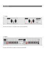
1. Device overview
1.1. Front panel
The connectors “Cat5 Connection 2“ are only available in the 64 channel version (ADX-64A-PRO).
1.2. Rear panel
The connectors „ADAT 5-8/WC“ are only available in the 64 channel version (ADX-64A-PRO).
User's Manual
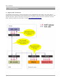
2. Typical application
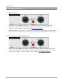
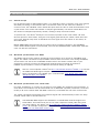
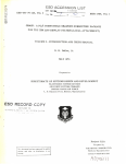
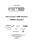
2.1. Digital snake (32 channels)
The diagram below shows a typical application of the ADAT Multicore Extender: One Cat5 cable is
used for both the transmission of 24 channels from the stage to the mix console, and 8 channels in the
opposite direction. All 32 channels are also fed into a monitor console and into a multitrack recorder.
Other examples setups can be found in chapter 10. Example applications.
4
ADX-32A / ADX-64A-PRO
3. Important safety notes
3.1. Cat5 connections
Use the Cat5 cable ONLY between ADAT Multicore Extenders!
NEVER connect an ADAT-Multicore Extender to any Ethernet networking device (PC,
Switch, other network equipment)! The ADAT Multicore Extender and/or the networking device may be DAMAGED!
4. Introduction
4.1. Overview
The ADAT-Multicore Extender devices are designed for building an inexpensive digital multicore
system, which acts, together with ADAT compatible mixers and converters, as an ideal
replacement for traditional analog multicores. The benefits are:
Heavily reduced cabling: one single Cat5 cable replaces 32 analog cables
No noise, hum, crackling etc. thanks to digital transmission and galvanic isolation
Very low latency (<0.6µs over 100ft Cat5 cable)
Simple, reliable and robust design
Scalable: available in 32 or 64 channel versions,
the 32 channel version can be easily upgraded to a 64 channel system
Wordclock distribution option (no coaxial cable needed) with the ADX-64A-PRO
Local loopback function provides ADAT pass-through on the same device. This allows the
connection of additional monitoring equipment or can be used as wordclock source
Compatible with all data formats using TOSLINK optical connectors:
ADAT Optical („ADAT Lightpipe“) 24bit/48kHz, ADAT S/MUX (Double Speed/DS, 24bit/96kHz),
ADAT S/MUX4 (Quad Speed/QS, 24bit/192kHz), SPDIF, AC-3, DTS etc.
Ruggedized 19“ aluminium rack case
Quality product „Made in Switzerland“
4.2. Applications
Using the ADX-32A, 4 ADAT Lightpipe-connections (32 channels of audio) can be transmitted
over a single Cat5 cable, up to a maximum distance of 330ft (100m).
Using the ADX-64A-PRO, 8 ADAT-Lightpipe connections (64 channels of audio) can be
transmitted over two Cat5 cables. This device also supports the transmission of a dedicated
wordclock signal (BNC connectors) along with the ADAT streams. When using this option, the
number of ADAT connections is reduced to 7 (56 channels of audio).
Both devices are designed for maximum flexibility: The direction of data transmission can be
selected individually for each ADAT connection. Thus, the ADX-32A can be operated in 32/0,
24/8, 16/16, 8/24 or 0/32 TX/RX channel configuration, and the ADX-64A-PRO can be
configured to 64/0, 56/8, 48/16 etc. to 0/64 of TX/RX channels.
5
User's Manual
For audio distribution to several places, up to 32 ADAT Multicore Extenders can be daisy-chained
together. This feature can be used for complex setups, e.g. multiroom audio distribution or the
connection of additional monitoring equipment. Each ADAT stream can be fed into the Cat5 at
an arbitrary place and is then distributed to all other connected devices.
All ADAT connections work completely independent of each other. This makes it possible to
transmit different data formats, sample rates, resolutions etc. at the same time over the same
Cat5 cable. This allows not only the ADAT protocol extensions S/MUX (DS/Double speed,
24bit/96kHz over 2 optical cables) and S/MUX4 (QS/Quad Speed, 24bit/192kHz over 4 optical
connections) but also many other encodings (S/PDIF, AES/EBU, AC-3) to be transmitted.
5. Theory of operation
5.1. Optical transmission
The commonly used ADAT Lightpipe interface (actually called “ADAT Optical“) uses Plastic
Optical Fiber (“POF“) as transmission media. POFs are very cheap and immune to
electromagnetic interference, but are limited to approx. 16ft (5m) transmission distance. Larger
distances cause problems as the light pulses are attenuated too much, leading to data errors
which usually result in drop-outs or crackles. Furthermore, POFs are also very sensitive to breaks
and sharp bends which may be a problem in harsh stage environments.
5.2. Electrical transmission
Electrical transmission over twisted pair cabling (e.g. Cat5) allows much longer distances than
POFs. Especially Cat5 cables are, as Ethernet cables, commonly used and very economic (many
buildings have Cat5 cables laid out already). Also, bending is not a problem, and for harsh
environments (like stage use), there is a selection of specially designed cable assemblies and
cable reels available, often using ruggedized Neutrik EtherCon® connectors.
Cat5 cable consists of four twisted pairs, each made up of two single wires. One pair can carry
one ADAT stream (8 channels), yielding a total transmission capacity of 32 channels.
The transmission method used on the Cat5 media is called “differential pair signalling” or
“balanced transmission”. This means that each signal is transmitted over a wire pair, where one
wire carries the inverted signal of the other one. In contrast to unbalanced (ground-referenced)
systems, differential signalling provides very good noise immunity, because coupled noise affects
both wires the same way and can be eliminated at the receiver's side by simply taking the
difference out. Additionally, EMI is greatly reduced because the electric and magnetic fields
surrounding the two wires cancel each other out.
The technology used in the ADAT Multicore Extender (RS-485) has been used for a long time,
e.g. for lighting applications (DMX) or harsh industrial environments (Profibus). The commonly
used AES/EBU standard works in a similar manner, but is, due to its relatively low data rate, only
able to transmit two audio channels over one pair. State-of-the-art technology is used in the
ADAT Multicore Extenders to ensure reliable operation at the higher data rates required by the
ADAT protocol.
6
ADX-32A / ADX-64A-PRO
5.3. Latency
Latency has – in contrast to traditional analog systems - always been a topic in digital audio
technology. High latency can lead to unwanted effects, such as phasing, hall, echo etc. and can
seriously affect audio performance. One design goal of the ADAT Multicore Extender was to
build a system offering one of the lowest latency values on the market. By design, other digital
snake solutions (e.g. Ethernet based systems) have a relatively high propagation delay, because
audio data has to be sampled, buffered, converted, transmitted, buffered and then finally
converted back to the original format. In contrast, ADAT Multicore Extender uses only minimal
buffering with no data conversion at all, achieving an excellent overall latency of less then 1µs.
5.4. Jitter
In any digital audio transmission, the clock signal picks up a certain amount of jitter (clock phase
noise). One must differentiate between two kinds of jitter (actually, two effects the jitter has on
an audio signal), as described below:
On one hand, there's the so called “sampling jitter”, occurring only at the point of digital-toanalog conversion or vice versa. Sampling jitter can cause distortion or noise since the timedomain information of a signal is altered. Today, DACs and ADCs make use of various advanced
re-clocking technologies in order to attenuate the jitter. Well designed equipment is no more
sensitive to sampling jitter regarding audio quality.
On the other hand, when jitter occurs on an interface used for the transmission of the data (e.g.
when used with an ADAT interface), it's called “interface jitter”. This kind is much less critical
since it only has an audible effect if its value is so large that it prevents the proper detection of
bits within the data stream (for AES/EBU, the specification allows a jitter value of ±20ns, which
is about 25% of a bit time). In a properly designed system, such high values should never occur.
To cope with jitter, other systems use often special re-clocking circuitry (Phase Locked Loop,
“PLL”). A PLL has good jitter attenuation characteristics, but must be specially adapted to the
used data format and sample rate in order to achieve optimal results. ADAT Multicore Extender
uses another approach: Instead of transmitting a signal with a relatively large gain of jitter and
then attenuating it with a PLL, it makes use of the most advanced transceiver technology
available, which has a very good out-of-the box jitter performance. The overall jitter of an ADAT
signal transmitted over 330ft (100m) Cat5 cable is only 4ns (typ.) which ensures correct bit
detection with an appropriate safety margin. This approach provides some advantages:
Very low latency since no buffering is required
Optimal transmission of arbitrary signals, independently of the encoding or speed
(e.g. ADAT, S/PDIF, AES/EBU, AC-3)
7
User's Manual
6. Front panel connections
6.1. Cat5 Connection 1
Cat5 cable carrying ADAT connections 1-4. Jacks “A” and “B” are electrically paralleled.
Depending on the number of jacks used, the push button “Termination” has to be set:
1 cable = “ON”, 2 cables = “OFF”. See also 8.1. Cat5 Termination.
NOTE: Redundant connections (the connection of two units with two cables over A and B at the
same time) are not supported! This would lead to signal loops causing undefined current flow.
6.2. Cat5 Connection 2 (ADX-64A-PRO only)
Cat5 cable carrying ADAT connections 5-8 and the wordclock signal. Jacks “A” and “B” are
electrically paralleled. Depending on the number of jacks used, the push button “Termination”
has to be set: 1 cable = “ON”, 2 cables = “OFF”. See also 8.1. Cat5 Termination.
8
ADX-32A / ADX-64A-PRO
7. Rear panel connections
7.1. Power Input
Power supply of the device. Use only the supplied DC adapter or a replacement with the
indicated voltage, power, polarity and matching connector (see 12. Specifications). The input
has a reverse-polarity protection. If the Power LED does not go on when a DC adapter is
connected, check the polarity (inner positive).
The second module in the 64 channel version is internally supplied with power.
7.2. ADAT 1-4
ADAT Lightpipe inputs and outputs 1-4. The direction (TX or RX) must be set using the DIP
switches, see 8.2. Transmission direction (ADAT 1-4).
7.3. ADAT 5-8/Wordclock (ADX-64A-PRO only)
ADAT Lightpipe Inputs/Outputs 5-8 and wordclock Input/Output. The direction (TX or RX) must
be set using the DIP switches, see 8.2. Transmission direction (ADAT 1-4).
Channel 5 can either be used as ADAT or as wordclock transmission, see 8.4. Channel 5 mode
selection (ADAT or Wordclock).
ADATs 5-8 may also be used to build a simple ADAT splitter. To do this, connect “Cat5
connection 1” to “Cat5 connection 2” using a short Cat5 cable
9
User's Manual
8. Settings
An overview of all switch settings can be found in 11. Settings overview.
8.1. Cat5 Termination
For proper operation, the termination (push button on the front panel) has to be set correctly.
The required setting depends on the position of the ADAT Multicore Extender within the cable
snake:
At devices on the end of a Cat5 snake (all devices having only one cable plugged in either A or
B), the termination has to be switched ON.
At devices in the middle of a Cat5 snake (all devices where cables are plugged into both jacks A
and B), the termination has to be switched OFF.
If you use only two devices (point-to-point connection), the termination must always remain
switched on.
Wrong termination settings are, depending on the cable length, not always noticeable
(the system appears to function properly). But reliability and immunity to noise is significantly decreased, because signals reflections can occur (with missing termination)
or the transmitters get overloaded (with too many terminations).
Please ensure therefore that the termination settings are correct under any circumstances.
If you're using the system in the same setup all time, you may use scotch tape to fix
the push button (or remove the push button cap) in order to prevent unwanted operation.
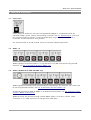
8.2. Transmission direction (ADAT 1-4)
The transmission direction (input or output) for ADAT connections 1-4 is set by the DIP-switches
1-4.
Input (DIP switch in lower position = OFF): The ADAT connection is configured as input (the
receiver is active). The received data is sent over the Cat5 cable.
The input signal is passed-through to the output alongside ("local loopback"). You can
use this output to connect additional monitors or as wordclock source, as shown in
9.2. Wordclock synchronization over ADAT.
10
ADX-32A / ADX-64A-PRO
Output (DIP switch in upper position = ON): The ADAT connection is configured as output (the
sender is active). Data received from the Cat5 cable is output on the “Output” jack.
Within a system, for each ADAT connection there must be only one sender (input) device.
8.3. Transmission direction (ADAT 5-8), ADX-64A-PRO only
The transmission direction (input or output) for ADAT connections 5-8 and the wordclock signal
is set by the DIP-switches 1-4.
8.4. Channel 5 mode selection (ADAT or Wordclock)
The mode of operation of channel 5 is user selecteable.
ADAT transmission: Set DIP switch #6 to “ON”. The direction can be set with DIP switch #1
(Output=“ON” , Input=“OFF”). The BNC wordclock jack is now disabled.
Wordclock transmission: Set DIP switch #6 to “OFF“. The direction of the wordclock
transmission can then be set with DIP switch #1 (Output=“ON”, Input=“OFF”).
ADAT Connection 5 is now disabled.
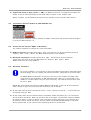
8.5. Wordclock termination
For proper operation, it is important to set the wordclock termination using DIP switch
#5 accordingly. (Do not confuse with Cat5 termination, switchable on the front side).
An ADAT Multicore Extender connected to the end of the wordclock coaxial cable
must have set the termination to ON (DIP switch #5=ON). If it is connected in the
middle of a coaxial cable (using a T-type connector), the wordclock termination must
be set to “OFF”.
NOTE: We recommend connecting the ADAT Multicore Extender on the end of the wordclock
cable (without T-type connector) with the termination set as follows:
At the input side (where the wordclock source – mixer, reference clock etc. - is connected, the
termination must be “ON”.
At the output side (where wordclock slaves, like DACs, ADCs, Recorders etc.) are connected,
the termination should be “OFF”. At the other end of the cable, a termination must be installed
by means of either a T-type connector with a 75 ohms resistor attached, or by switching on a
termination resistor within the device. There are different possibilities depending on the used
device, please refer to the manual of the respecting device for instructions.
11
User's Manual
The above configuration with only one cable end terminated is possible if the transmitter device
is located at the other end of the cable and has the advantage of lowering the driver's load.
However, if you have the ADAT Multicore Extender connected in the middle of the cable, both
ends must be terminated.
12
ADX-32A / ADX-64A-PRO
9. Wordclock synchronization
9.1. General concept
For all devices within a digital audio system, it is required to share a common clock. This ensures
that data processing on all channels and on all devices is done at the same rate. Without a
common clock, the individual clocks would drift apart with time due to small skew between even
crystal clocks. This means that number of samples generated by one device would differ from
the number of samples expected by another, leading to drop-outs and crackles.
To prevent this, one device (usually the mix console) operates at the clock master. All other
devices operate in slave mode, using the clock signal generated by the master rather than their
own clock. Several ways exist to distribute the clock signal from the master to the slaves, as
described below.
NOTE: ADAT Multicore Extenders do not need a clock to operate. However, the embedded
clocks within ADAT signals are transmitted, and with the ADX-64A-PRO, a dedicated (separate)
clock can also be transmitted.
9.2. Wordclock synchronization over ADAT
Any ADAT signal can be used for wordclock synchronization as it carries an embedded clock
signal. The master clock device outputs ADAT streams with the master clock timing embedded,
and all slaves can extract the embedded wordclock from the stream. Please refer to your
equipment's manual to ensure the appropriate wordclock source setting of the device.
If ADAT synchronization is used, no additional wordclock cabling is required.
Use the "local loopback” feature (see 8.2. Transmission direction (ADAT 1-4) to break
out additional ADAT signal outputs which can be used as wordclock source. An example configuration using ADAT sync is shown under 10.2. Digital 24/8 multicore
(Wordclock-Sync over ADAT).
9.3. Wordclock synchronization over coaxial cable
For larger installations, it is often not convenient to use ADAT for wordclock synchronization. In
such cases, the wordclock can be transmitted over a dedicated (separate) wordclock connection,
usually a 75 ohms coaxial cable with BNC connectors, terminated with 75 ohms at both ends.
The master clock device generates the wordclock signal and is distributed by means of a daisychained coaxial cable to all slave devices.
The ADX-64A-PRO supports the distribution of a dedicated wordclock signal over
Cat5 cables. This means that you do not need a separate coaxial cable along with
your Cat5 cabling. For details, see 8.4. Channel 5 mode selection (ADAT or Wordclock). An example configuration is shown under 10.3. Digital 40/16 multicore (Wordclock-Sync over dedicated coaxial cable).
13
User's Manual
10. Example applications
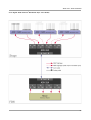
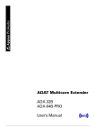
10.1. Digital 16/16 multicore
14
ADX-32A / ADX-64A-PRO
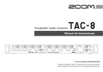
10.2. Digital 24/8 multicore (Wordclock-Sync over ADAT)
15
User's Manual
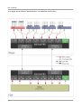
10.3. Digital 40/16 multicore (Wordclock-Sync over dedicated coaxial cable)
16
ADX-32A / ADX-64A-PRO
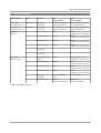
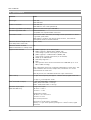
11. Settings overview
Switch location
Function
ON
(upper position)
OFF
(lower position)
Front panel
Termination
“Cat5 Connection 1”
Cat5 cable
termination
One cable connected to
“Cat5 Connection 1”
Two cables connected to
“Cat5 Connection 1”
Front panel (*)
Termination
“Cat5 Connection 2”
Cat5 cable
termination
One cable connected to
“Cat5 Connection 2”
Two cables connected to
“Cat5 Connection 2”
Rear panel
ADAT 1-4
1
ADAT 1 direction
Output
Input
(Output acts as loopback)
2
ADAT 2 direction
Output
Input
(Output acts as loopback)
3
ADAT 3 direction
Output
Input
(Output acts as loopback)
4
ADAT 4 direction
Output
Input
(Output acts as loopback)
5
No function
6
No function
1
ADAT 5/Wordclock
direction
Output
Input (Output acts as
loopback in ADAT mode)
2
ADAT 6 direction
Output
Input
(Output acts as loopback)
3
ADAT 7 direction
Output
Input
(Output acts as loopback)
4
ADAT 8 direction
Output
Input
(Output acts as loopback)
5
Wordclock
termination
75 ohms termination
active
No termination
6
Channel 5 mode
ADAT 5
(Wordclock disabled)
Wordclock
(ADAT 5 disabled)
Rear panel
ADAT 5-8/WC (*)
Label
(*) ADX-64A-PRO model only
17
User's Manual
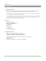
12. Specifications
Parameter
Value
Device type
ADX-32A
ADX-64A-PRO
Number of channels
ADX-32A: 32
ADX-64A-Pro: 64 (or 56+Wordclock)
Connector type ADAT Input/Output
Optical connector F05 type (TOSLINK ®)
Connector type Cat5 cable
Neutrik EtherCon®,
compatible with standard RJ45 connectors
Transmission media
Twisted-Pair cable (100 ohms) according to Cat5 specification or better
(e.g. Cat5e, Cat6, Cat7)
DMX cabling(110 Ohm) may also be used, however, the maximum
transmission distance could be reduced.
Maximum distance (length of the
entire daisy-chain end-to-end)
330ft (100m)
Maximum number of ADAT
32
Multicore Extenders on a daisy-chain
Supported data formats
ADAT Lightpipe ® up to 48kHz 24bit
ADAT Lightpipe ® 96kHz 24bit (S/MUX, DS)
(when using 2 optical connections per 8 channels)
ADAT Lightpipe ® 192kHz 24bit (S/MUX4, QS)
(when using 4 optical connections per 8 channels)
S/PDIF up to 96kHz/24bit
AC3/Dolby Digital 5.1 ®
DTS ®
other formats which can be transmitted over TOSLINK® up to 13.2
Mbit/s (NRZ encoding).
All 4 transmission lines work completely independent of each other. This
means different data formats, sample rates, resolutions etc. can be
transmitted at the same time.
With all formats, the embedded wordclock is also transmitted.
ADAT Latency
<0.4µs (entire system) plus approx. 1.6ns/ft (5ns/m) signal travel time
<0.4µs in „local loopback” mode
Jitter (measured at output)
3ft (1m) Cat5 cable: ±2.5ns typ.
100ft (30m) Cat5 cable: ±3ns typ.
330ft (100m) Cat5 cable: ±4ns typ.
Wordclock input/output
(ADX-64A-PRO only)
configured as input:
“H”-level: 1.55 V
“L”-level: 1.15V
configured as output:
“H”-level: 3.11V an 75 Ω
“L”-level: 0.15V
short-circuit protected
Termination (75 Ω) built-in, switchable
Latency: <0.1µs (entire system) plus approx. 1.6ns/ft (5ns/m) signal
travel time
18
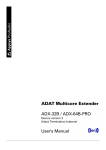
ADX-32A / ADX-64A-PRO
Pinout Cat5 cable
Jacks A+B are paralleled
Pin
Signal
1
ADAT1+ (ADAT 5/WC +*)
2
ADAT1— (ADAT 5/WC —*)
3
ADAT2+ (ADAT 6+*)
4
ADAT3+ (ADAT 7+*)
5
ADAT3 — (ADAT 7—*)
6
ADAT2 — (ADAT 6—*)
7
ADAT4+ (ADAT 8+*)
8
ADAT4— (ADAT 8—*)
* ADX-64A-PRO: Connections 5-8
Cat5 protection
Short-circuit protected
Electrostatic discharge (ESD) protection:
±15 kV according to IEC 61000-4-2
Power supply
8..24V DC 5W, Polarity:
(inner positive)
Plug type: ID=2.5mm, OD=Ø 5.5mm, Length=9mm
Supplied DC adapters are isolated from earth
Cat5 cable shield is connected to GND
Temperature range
Operation: 32°F...140°F (0°C...+60°C)
Storage: 14°F...140°F (-10°C...+60°C)
Dimensions
19“ rack 1HE
60mm in depth
19
User's Manual
13. Warranty
13.1. Terms and conditions
We offer a full warranty within two (2) years from the date of purchase. Within the warranty
period , we repair or exchange your device free of charge in case of a defect (*)
If you experience any problems, please contact us first. We try hard to solve your problem as
soon as possible - even after the warranty period.
(*) Not covered by the warranty are any damages resulting out of improper use, willful damage,
normal wear-out (especially of the connectors) or connection with incompatible devices like
Ethernet equipment or third-party power supplies.
13.2. Contact
Application Systems
Dipl.-Ing. (FH) Rolf Eichenseher
Bullingerstr. 63 / BK241
CH-8004 Zürich
Switzerland
www.appsys.ch
[email protected]
Tel. +41 22 550 05 42
13.3. About this document
ADAT® is a registered Trademark of Alesis Corp.
TOSLINK® is a registered Trademark of Toshiba Corp.
EtherCon® is a registered Trademark of Neutrik AG
All information provided here is subject to change without prior notice.
Document Revision: 4
2009-11-18
Copyright © 2009 Application Systems Rolf Eichenseher
20