1
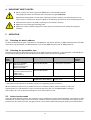
reduc Microphone Preamp Remoting Kit Remote Gain Controller RGC-24A-M w/accessories User's Manual CONTENTS 1. DEVICE OVERVIEW.................................................................................................................................................... 4 1.1. Kit Contents........................................................................................................................................................ 5 2. INTRODUCTION......................................................................................................................................................... 5 2.1. Supported Microphone Preamps...................................................................................................................... 5 2.2. Features.............................................................................................................................................................. 5 3. TYPICAL APPLICATIONS........................................................................................................................................... 7 3.1. Remote gain control with mixer at FOH............................................................................................................ 7 3.2. Remote gain control with mixer on stage......................................................................................................... 8 4. IMPORTANT SAFETY NOTES.................................................................................................................................... 9 5. OPERATION................................................................................................................................................................ 9 5.1. Selecting the device address............................................................................................................................. 9 5.2. Selecting the preamplifier type......................................................................................................................... 9 5.3. Active/passive mode.......................................................................................................................................... 9 5.4. Reset/power cycle behavior............................................................................................................................ 10 6. PREAMP MODIFICATION (ALL PREAMPS)............................................................................................................. 11 6.1. Overview.......................................................................................................................................................... 11 6.2. Modded device behavior................................................................................................................................. 11 6.3. Prerequisites .................................................................................................................................................... 11 6.4. Circuit............................................................................................................................................................... 11 7. COUPLER INSTALLATION........................................................................................................................................ 12 7.1. Choose your D-Sub connector installation method....................................................................................... 12 7.2. Method 1: D-Sub cable hanging out of preamp (quickest way)....................................................................12 7.3. Method 2: D-Sub jack mounted (more work- shown in ADA8000 pictures).................................................13 8. BEHRINGER ADA8000............................................................................................................................................. 14 9. FOCUSRITE OCTOPRE MKII.................................................................................................................................... 18 10. RME OCTAMIC....................................................................................................................................................... 20 11. ART TUBEOPTO 8.................................................................................................................................................. 21 12. MACKIE ONYX 800R.............................................................................................................................................. 21 13. PRESONUS DIGIMAX D8....................................................................................................................................... 21 14. MIDI INTERFACE.................................................................................................................................................... 22 14.1. Channel/Controller/Value setup..................................................................................................................... 22 14.2. Operation from standalone Windows software............................................................................................22 14.3. Operation from VST plugin (e.g. from SAC)................................................................................................. 22 14.4. Operation from Behringer BCR2000/BCF2000 MIDI Controller....................................................................23 14.5. Operation from Yamaha mix consoles (DM2000, 01v96).............................................................................23 14.6. Testing and Troubleshooting......................................................................................................................... 24 15. ADVANCED TOPICS............................................................................................................................................... 26 15.1. List of advanced settings............................................................................................................................... 26 15.2. Changing advanced settings......................................................................................................................... 27 15.3. Preamp requirements for remote gain control............................................................................................. 27 15.4. Matching the control curve to your preamp................................................................................................. 28 15.5. Reset to Factory Defaults............................................................................................................................... 28 16. SPECIFICATIONS.................................................................................................................................................... 29 17. APPENDIX.............................................................................................................................................................. 30 17.1. Warranty......................................................................................................................................................... 30 17.2. Contact........................................................................................................................................................... 30 17.3. Recycling........................................................................................................................................................ 30 17.4. Acknowledgements....................................................................................................................................... 30 17.5. About this document..................................................................................................................................... 30 3 1. DEVICE OVERVIEW Element Function “ACTIVE” LED On when the controller is active (gain control is enabled), off when the controller is inactive. If a valid MIDI command is detected, the light goes dark for a moment to indicate reception. “ACTIVE” Button Press to toggle between active and inactive mode. To perform “factory defaults reset”, press and hold down while connecting power until the “ACTIVE” LED flashes three times. DIP Switch Switch Meaning 1/2 Selects the MIDI channels to which the device responds to: OFF/OFF: Channels 1/2/3 (for preamps 1/2/3) OFF/ON: Channels 4/5/6 (for preamps 1/2/3) ON/OFF: Channels 7/8/9 (for preamps 1/2/3) ON/ON: Channels 10/11/12 (for preamps 1/2/3) 3/4 Selects the preamp type for PREAMP1, PREAMP2 and PREAMP3: OFF/OFF: Behringer ADA8000 (5k neg. log) OFF/ON: Focusrite OctoPre MkII (25k neg. log) ON/OFF: unused ON/ON:: Digital mode for 5V/500 Ohms Reed relays (e.g. for pad/phantom power switching) 5/6 7/8 “POWER” LED On when the device is powered up “POWER” Jack Power input “IN” Jack MIDI Input “THRU” Jack MIDI Thru. All data received on “IN” is passed to “THRU” without modification to allow daisy-chaining of MIDI equipment. “PREAMP 1” Jack To preamp #1 (optocouplers 1-8) “PREAMP 2” Jack To preamp #2 (optocouplers 9-16) “PREAMP 3” Jack To preamp #3 (optocouplers 17-24) Table 1: Overview of the device 4 1.1. Kit Contents The kit contains everything you need to bring remote gain control to three eight-channel preamps: Remote Gain Controller box, model RGC-24A-M Power supply 12V, 1A 24 high-grade analog optocouplers, individually selected to match to +/-5% resistance value 3 pcs. D-SUB cable, 9 pin, 1:1 male-female (for connecting the preamps to the controller) 3 pcs D-SUB connectors, 9 pin, male, for preamp mounting 3 pcs. flat ribbon cable, 9 pin, for connecting optocouplers to the D-SUB Insulated copper wire, for connecting the common anode of the couplers together Green LED for testing purposes Cable tie for strain relief This manual 2. INTRODUCTION 2.1. Supported Microphone Preamps Currently, preamps with 5k to 50k logarithmic potentiometers are supported. Typical models using these values are: Behringer ADA8000 Focusrite OctoPre MkII Focusrite OctoPre Dynamics ART TubeOpto 8 Presonus Digimax D8 Mackie Onyx 800R RME Octamic RME Octamic II all other preamps with pots in 2-pin configuration – contact us if you are unsure about your model. Remote switching of digital functions (e.g. pad or phantom power) via reed relays is also supported. The required relays are not included, please contact us for model recommendations. 2.2. Features The Microphone Preamp Remoting Kit adds remote gain control capability to your existing preamps, enabling you to position your microphone preamps on stage. Gain control is achieved by paralleling the existing potentiometers with high-class, analog optocouplers driven by an external control box (the Remote Gain Controller). When active, these couplers take over the function of the mechanical potentiometers for gain adjustment. The individual gain levels can be set using standard MIDI commands. The system has many advantages over other solutions: Allows to re-use existing preamps One RGC-24A-M controls up to 24 channels (e.g. three eight-channels preamps). Can be extended up to four controllers (96 channels) Sound quality and characteristics of your preamps remain unchanged Very simple installation, needs only two solder points per channel within the preamp Non-intrusive mod, can easily be undone No further modification of the original circuit Preset control curves (gain vs. resistance) for different preamps Automatically remembers last gain settings on power up Control curves can be altered by the user for perfect matching to any preamp type 5 Modified preamps retain original gain control function Full opto-isolation between preamp and control box Passive design, does not draw power from the preamp's supply Quality product „Made in Switzerland“ 6 3. TYPICAL APPLICATIONS 3.1. Remote gain control with mixer at FOH Preamp Preamp Remote RemoteGain GainController Controller RGC-24A-M RGC-24A-M Preamp Preamp Preamp/DAC Preamp/DAC Stage ADAT ADATMulticore MulticoreExtender Extender ADX-32B ADX-32B ADAT Lightpipe connection MIDI connection Cat.5 connection D-Sub connection ADAT Multicore Extender ADAT Multicore Extender ADAT Multicore Extender ADX-32B ADAT Multicore Extender ADX-32B ADX-32B ADX-32B MIDI MIDI Controller Controller Mix Mixconsole console FOH Picture 1: Digital multicore (24/8 configuration) with remote gain control 7 3.2. Remote gain control with mixer on stage Preamp Preamp Remote RemoteGain GainController Controller RGC-24A-M RGC-24A-M Preamp Preamp Preamp/DAC Preamp/DAC Mix Mixconsole console(e.g. (e.g.PC PCrunning runningSAC) SAC) Stage ADAT Lightpipe connection MIDI connection Network connection D-Sub connection ADAT Multicore control Extender for ADX-32B ADATRemote Remote Multicore control Extender formixer mixer ADX-32B FOH Picture 2: Remote gain control with mixer on stage 8 4. IMPORTANT SAFETY NOTES Never connect any other equipment (RS232 etc.) to the D-SUB outputs! The equipment and/or the Remote Gain Controller may get DAMAGED! Microphone preamplifiers contain parts operating at mains voltage. Only trained persons may open, repair or modify such devices! Observe the following precautions when modifying devices: Disconnect the mains cord before opening any microphone preamp Make sure not to damage insulating parts Make sure newly installed equipment is kept away from internal mains voltage and properly isolated. 5. OPERATION 5.1. Selecting the device address To allow multiple remote gain controllers on one MIDI port, the device address (= MIDI channels) where the RGC responds to can be altered. Use DIP-Switches 1/2 to set the MIDI channels (see 14. MIDI Interface). 5.2. Selecting the preamplifier type The RGC supports four different control curves for different types of preamps.. Curve selection is individually for each preamp output, that means that different preamps can be mixed on a single RGC. DIP “AMP TYPE” setting Preamp models Coupler type Potentiometer mimic Minimum firmware version * OFF OFF Behringer ADA8000 ART TubeOpto 8 Presonus Digimax D8 Mackie Onyx 800R Silonex NSL32-SR2 5..10k negative logarithmic 1 OFF ON Focusrite OctoPre MkII Focusrite OctoPre Dynamics RME Octamic RME Octamic II Silonex NSL32-SR2 25..50k negative logarithmic 2 ON OFF Reserved for custom preamp curve ON ON - Digital mode 2 5V/500 Ohm Reed Relays * See bottom of the device for firmware version. For upgrading, please contact us. We will continue to add more pre-defined curves on customer request; please contact us with your requirements. The characteristic curves can also be altered by the user via MIDI SYSEX messages. See Chapter 15.1 List of advanced settings for more information on this. 5.3. Active/passive mode Using the white “ACTIVE” button, the controller can be switched to inactive mode (disabled). All outputs are then switched off, and the couplers reach maximum resistance (several mega-ohms). This makes them appear to the preamp as if they were removed, and gain control can be done traditionally using the preamp's potentiometers. 9 5.4. Reset/power cycle behavior All settings, including active/passive mode and gain values, are stored in an internal EEPROM which retains its contents even when power is disconnected. On power up, all settings are restored to their last values. 10 6. PREAMP MODIFICATION (ALL PREAMPS) 6.1. Overview The mod is basically the same for all preamp types. Differences are only in respect to the coupler connection points and the mounting of the D-Sub connector. In this chapter is described only what is common to all preamps. For detailed instructions about your particular preamp model see the corresponding section. 6.2. Modded device behavior The stock gain potentiometer continues to function as before if the remote gain controller is not connected or if it's switched off. To experience remote control magic, turn all knobs to the leftmost (minimum position) and switch on the remote gain controller – now you are able to adjust the gains from everywhere, using common MIDI controllers. Limitations You cannot mix local and remote control, but you can switch between both modes. The maximum gain which is achievable in in remote-control mode is a few dB lower than with the original pot, because the couplers don't reach 0 ohms minimum resistance. 6.3. Prerequisites Screwdrivers for opening your preamp Wire cutter Solder iron and wire Additionally, if you decide to mount the D-Sub jack into the preamp: Saw and/or fretsaw, or preferably a mini-grinder tool (e.g. DREMEL with cut-off wheel) Small flat file for smoothening of the cutout edges 3mm drill 5mm wrench Bench vise for press-fitting the connector 6.4. Circuit The optocoupler's outputs are installed in parallel to the potentiometers. The input (LED) terminals are connected to the D-Sub connector, with common anode on pin 1 and cathodes on pins 2 to 9. 11 7. COUPLER INSTALLATION Picture 3: Pinout of Silonex NSL-32SR2 7.1. Choose your D-Sub connector installation method Depending on how much time you are willing to spend, you can choose between two methods of how to establish the D-Sub connection out of your preamp. 7.2. Method 1: D-Sub cable hanging out of preamp (quickest way) 1. 2. 3. 4. Cut off the female jack from the supplied D-Sub cables Drill a hole anywhere in the rear of your preamp, large enough for the cable, and feed it through. Locate the potentiometer terminal solder points on the front PCB (see the re) Cut the coupler wires “Ra” and “Rb” to about 20mm length and solder them to the potentiometer terminals. 5. Use the enameled copper wire to connect the anode (“A” terminals) of all couplers together. To remove the insulation and wet them with solder, heat the wire with the solder iron for about 20 seconds at 400°C. Note: This must be done before connecting the wire to the couplers as they can be damaged by excessive heat. 6. Strip off the cable jacket, and solder the wires directly to the couplers. The table below shows a popular assignment of cables colors to pins, but please check with a multimeter before as there are cables around using another color/pin mapping scheme! Pin 1 black All Anodes Pin 2 brown Cathode Ch 2 Pin 3 red Cathode Ch 4 Pin 4 orange Cathode Ch 6 Pin 5 yellow Cathode Ch 8 Pin 6 green Cathode Ch 1 Pin 7 blue Cathode Ch 3 Pin 8 violet Cathode Ch 5 Pin 9 white Cathode Ch 7 7. Use cable ties and/or hot-melt to fix the wires to the anode wire as required. 12 7.3. Method 2: D-Sub jack mounted (more work- shown in ADA8000 pictures) 1. Locate the potentiometer terminal solder points on the front PCB 2. Cut the coupler wires “Ra” and “Rb” to about 20mm length and solder them to the potentiometer terminals. 3. Use the enameled copper wire to connect the anode (“A” terminals) of all couplers together. To remove the insulation and wet them with solder, heat the wire with the solder iron for about 20 seconds at 400°C. Note: This must be done before connecting the wire to the couplers as they can be damaged by excessive heat. 4. Prepare the ribbon cable: Insert the cable into the D-SUB connector with conductor #1 (red) on Pin 1 of the connector. Pin 1 is upper left when looking at the mating face. 5. Make sure the cable is straightly oriented to the connector before press-fitting the connector (this can be done using a bench vise. Be careful only to apply gentle force in order not to damage the connector). 6. Solder conductor #1 (red) of the ribbon cable to the “A” terminal of coupler at CH1 7. Solder conductor #2 to “C” terminal of coupler at CH1 8. Solder conductors #3...#9 to “C” terminals of couplers at channels CH2...CH8 9. Use cable ties to fix the wires to the anode wire as required. 10. Mark a rectangular cutout on the rear of the preamp 11. Apply some protection (for example, plastic foil) over the PCB to protect it from metal chips. 12. Cut the area using a saw (fretsaw), or a small grinder tool (e.g. DREMEL) with cutting disc. 13. Trim the edges using a file 14. Carefully remove all metal chips and metal dust from the interior of the preamp, especially from the PCBs. This can be done using an old toothbrush and a vacuum cleaner. 15. Insert the 9-pin connector and mark the position of the holes 16. Remove the connector and drill 2 at the marked position (Ø3mm) 17. Mount the connector using the supplied bolts with flat washers on the front, and the spring washers and nuts on the rear 18. Fix the ribbon cable on the mainboard as required. 13 8. BEHRINGER ADA8000 Picture 4: Remove the top cover (6 screws, different sizes!) Picture 5: Remove both rack mount flanges Picture 6: Remove 3 screws from the bottom 14 Picture 7: Disconnect the 9 cables to the front panel from the main PCB Picture 8: Solder points for couplers Picture 9: Closeup Picture 10: Coupler orientation 15 Picture 11: Coupler wiring Picture 12: Front panel (complete) Picture 13: D-Sub cutout Picture 14: Drill markings Picture 15: Installed D-Sub Picture 16: Interior 16 Picture 17: Isolation tape on shielding Picture 18: Complete assembly Picture 19: Finished! 17 9. FOCUSRITE OCTOPRE MKII Picture 20: Screws to lift before Picture 21: Solder points Picture 22: Solder points Picture 23: Coupler orientation Picture 24: Installed couplers 18 Picture 25: Modded front panel Picture 26: Finished! 19 10. RME OCTAMIC Picture 27: Coupler installation Picture 28: Coupler closeup Picture 29: Finished! 20 11. ART TUBEOPTO 8 Picture 30: Solder points (Ch1 not shown) 12. MACKIE ONYX 800R No pictures yet – if you have one, please take a picture and send it to us! 13. PRESONUS DIGIMAX D8 No pictures yet – if you have one, please take a picture and send it to us! 21 14. MIDI INTERFACE 14.1. Channel/Controller/Value setup Gain adjustment is done via standard MIDI control commands: The preamp (1, 2 or 3) is selected by the MIDI channel The optocoupler (1 to 8) is selected by the controller number The gain value is set by adjusting the controller's value The raw MIDI bytes are indicated in [square brackets] DIP Address setting OFF OFF MIDI Channel * 2 = Preamp 1 [0xB1] 3 = Preamp 2 [0xB2] 4 = Preamp 3 [0xB3] OFF ON 5 = Preamp 1 [0xB4] 6 = Preamp 2 [0xB5] 7 = Preamp 3 [0xB6] ON OFF 8 = Preamp 1 [0xB7] 9 = Preamp 2 [0xB8] 10 = Preamp 3 [0xB9] ON ON 11 = Preamp 1 [0xBA] 12 = Preamp 2 [0xBB] 13 = Preamp 3 [0xBC] Controller number * Gain value 24 25 26 27 28 29 30 31 0...127 [0x00...0x7F] = Optocoupler 1 [0x18] = Optocoupler 2 [0x19] = Optocoupler 3 [0x1A] = Optocoupler 4 [0x1B] = Optocoupler 5 [0x1C] = Optocoupler 6 [0x1D] = Optocoupler 7 [0x1E] = Optocoupler 8 [0x1F] 0 = minimum gain 127 = maximum gain Resulting gain in dB depends on preamp type, for ADA8000 0...127 means +10..+50dB (approx 0.3dB steps) * These values and mappings can further be changed using SYSEX commands (see Advanced Topics). Examples (The following examples assume that the “ADDR.” DIP switches are both “OFF”): To set the gain on preamp 1, channel 1, to 63 (mid-scale): On MIDI channel 2, set controller number 24 to value 63 [Raw byte sequence: 0xB1 0x18 0x3F] To set the gain on preamp 3, channel 8, to 0 (minimum): On MIDI channel 4, set controller number 31 to value 0 [Raw byte sequence: 0xB3 0x1F 0x00] 14.2. Operation from standalone Windows software For PCs running Windows, a standalone software with full scene save & recall is available is available on our web page: http://appsys.ch/downloads/rgc-pc-software 14.3. Operation from VST plugin (e.g. from SAC) There is a VST plugin available which can be used with any VST-enabled software: http://appsys.ch/downloads/rgc-pc-software 22 14.4. Operation from Behringer BCR2000/BCF2000 MIDI Controller These hardware MIDI controllers are a very straightforward way to control the gains. Especially the BCR2000 variant is recommended, because it features 24 distinct rotary knobs which can be mapped to control four RGC24A-Ms (96 channels total). It supports also full scene recall and can be combined with any mix console. A preset file (.SYX) for the BCR2000 can be downloaded from our web page at http://appsys.ch/downloads/rgc-bcr2000-template 14.5. Operation from Yamaha mix consoles (DM2000, 01v96) The place where the settings can be done is the “Remote Layer” (available in the “Remote” menu), and not (as one might assume) within the MIDI menu! The gain setting can be operated by the rotary encoders and/or the faders. In the example below, we map Remote Layer 1/Fader 1 to RGC1, Preamp 1, Ch1 Remote Layer 1/Fader 2 (and Encoder 2) to RGC1, Preamp 1, Ch2 Remote Layer 1/Fader 3 to RGC1, Preamp 1, Ch3 Programming procedure: 1. Select menu “REMOTE”, then “REMOTE1” 2. Select TARGET= “USER DEFINED” 3. Select TRANSMIT = “ENABLED” 4. ID (RM01) equals fader/encoder 1, ID (RM02) equals fader/encoder 2 and so on 5. for Fader 1, enter “B1 – 18 – FAD – END” 6. for Fader 2, enter “B1 – 19 – FAD – END” (or “B1 – 19 – ENC – END” if you want to use the encoder) 7. for Fader 3, enter “B1 – 1A – FAD – END” 8. Repeat steps 4 & 5 with the respective data for the rest of the controllers (B1-B3 = Preamp 1-3, 18-1F = Ch 1-8 etc.) Picture 31: Setup of Ch1 23 Picture 32: Setup of Ch2 Picture 33: Setup of Ch3 14.6. Testing and Troubleshooting To test if your MIDI controller is configured correctly for the RGC: Observe the yellow “ACTIVE” LED while adjusting gain. If a MIDI command to the RGC was recognized, the LED goes dark for a moment to show the command's acceptance. If the LED remains on, double-check that: - MIDI channels match the RGC's configuration (DIP-Switch setting) - MIDI controllers match the RGC's expected values 24 Use the supplied green LED to test if the controller is actually working. Insert the longer wire (anode) into contact #1 from D-SUB connector on the RGC, and the shorter wire into any of contacts #2 to #9. The LED should change brightness when gain values change (dark at value 0, fully lit at value 127). Hint: The pins numbers are printed on the D-SUB jack (very small). Pin Function Pin Function 1 Common Anode 6 Cathode CH1 2 Cathode CH2 7 Cathode CH3 3 Cathode CH4 8 Cathode CH5 4 Cathode CH6 9 Cathode CH7 5 Cathode CH8 25 15. ADVANCED TOPICS 15.1. List of advanced settings To allow interfacing with almost every MIDI controller, whether in software or hardware, the RGC-24A-M allows fine-grain control of its behavior via “GLOBAL PARAMETERS”: The MIDI channel to which the RGC responds can be set to any value (0 ...15) The MIDI controller numbers on which the gain controls live can be altered to any value (0...127) The number of MIDI controllers on each channel can be adjusted. The default of 8 controllers per channel can be altered e.g. to 24 controllers on only one channel. The curve characteristics (the mapping between controller value and resistance) can be defined by the user. Each curve is defined by 17 values, dividing the gain entire control range into 16 sections. Slot Parameter Possible values Default value 00: General Configuration 01: MIDI channel base when DIP-Switches 1/2 are set to OFF/OFF 0x00 ...0x0F 0x01 (= Channels 2,3,4) 02: MIDI channel base when DIP-Switches 1/2 are set to OFF/ON 0x00 ... 0x0F 0x04 (= Channels 5,6,7) 03: MIDI channel base when DIP-Switches 1/2 are set to ON/OFF 0x00 ... 0x0F 0x07 (= Channels 8,9,10) 04: MIDI channel base when DIP-Switches 1/2 are set to ON/ON 0x00 ... 0x0F 0x0A (= Channels 11,12,13) 05: MIDI controller base 0 ...127 (0x00 ... 0x7F) 0x18 (= Controllers 24...31) 06: Number of controllers per 0x00 ... 0x18 MIDI channel 01: Curve adjustment for curve #1 00 ... 16: Curve node index 0x000 ... 0xFFF (0 ... 4095) 02: Curve adjustment for curve #2 00 ... 16: Curve node index 0x000 ... 0xFFF (0 ... 4095) 03: Curve adjustment for curve #3 00 ... 16: Curve node index 0x000 ... 0xFFF (0 ... 4095) 04: Curve adjustment for curve #4 00 ... 16: Curve node index 0x000 ... 0xFFF (0 ... 4095) Table 2: List of Global Parameters 26 0x08 15.2. Changing advanced settings This is done according to the “General MIDI” (GM1) standard, using the message “GLOBAL PARAMETER CONTROL”. This message is defined as follows: Byte value Meaning F0 7F Universal RealTime SysEx header Remarks Byte value Meaning 04 05 01 01 02 DEVICE CONTROL GLOBAL PARAMETER CONTROL Slot Path Length Parameter ID Width Value Width Set according to DIP 00 <Slot> <Param ID> <Value LSB> <Value MSB> [<Param ID>] [<Value LSB>] [<Value MSB>] Slot Number MSB Slot Number LSB Parameter ID Value lowest 7 bits Value highest 7 bits Parameter ID Value lowest 7 bits Value highest 7 bits ... ... ... F7 Remarks Byte value <Address> [<Param ID>] See Table 3 See Table 3 [<Value LSB>] [<Value MSB>] Meaning End of SYSEX message Remarks If the command is accepted, the “ACTIVE” LED goes dark for a moment. Example 1: To change the behavior in such a way that all three preamps are on MIDI channel 5, mapped to controller numbers 64 to 88, we need to adjust the settings in slot 00. We assume that DIP-Switches 1/2 are OFF/OFF, and the device has its default configuration of MIDI base channel 0x01. set the MIDI channel base (parameter 01) to 0x04 (the channel base is the number of the first MIDI channel minus 1) the controller number base (parameter 05) to 0x40 the number of controllers per channel (parameter 06) to 24 (0x18): F0 7F 01 04 05 01 01 02 00 00 01 04 00 05 40 00 06 18 00 F7 Note that the MIDI channel where the controller responds to has been altered. The new MIDI channel becomes effective after power is cycled. Subsequent commands then need to start with F0 F7 05. Example 2: We assume that DIP-Switches 1/2 are OFF/OFF, and the device has its default configuration of MIDI base channel 01. To adjust curve #2 (example: 5k neg log, using Silonex NSL-32SR2) with y-values of 0,4,8,12,20,32,44,64,84,140,204,300,456,724,1196,2080,4095 execute F0 7F 01 04 05 01 01 02 00 02 00 00 00 01 04 00 02 08 00 03 0C 00 04 14 00 05 20 00 06 2C 00 07 40 00 08 54 00 09 0C 01 0A 50 01 0B 2C 02 0C 48 03 0D 54 05 0E 2C 09 0F 20 10 10 7F 1F F7 15.3. Preamp requirements for remote gain control The controller can be adjusted to function with nearly every microphone preamp, if it meets the following conditions: 27 The original gain potentiometer is used in “rheostat” (2-pin) configuration; this is the case with standard 3-pin potentiometers if the wiper is connected to one of the other terminals. The original gain potentiometer has a nominal value between 5k or 50k. Larger values are possible, but require other type of optocouplers. Please contact us with your requirements. The minimum resistance with the supplied NSL-32SR2 couplers is about 40 Ohms. Depending on your preamp model, this may limit the range of gain adjustment which can be achieved (in case of ADA8000, the gain range which can be remoted is from +10dB to +50dB; vs. the original range of +10dB to +60dB. This is rarely a problem as most preamps produce a significant amount of noise in the high gain ranges). Some preamps use stereo (or even more channel) potentiometers for gain control. It is possible to mod such models by adding additional optocouplers in series configuration, but you may need to swap the voltage regulator inside the RGC-24A-M to compensate the higher forward voltage of the coupler's LEDs. Please contact us for details. 15.4. Matching the control curve to your preamp The remote gain controller is a precision, low-noise current source which controls the optocouplers light sources (LEDs). It delivers a controlled current in the range of 0 … 25mA, adjustable in 10bit precision (1024 linear steps, or about 24µA/step). Because gain control is usually done using a log taper potentiometer, and also the optocoupler has a log control characteristic, one must emulate logarithmic behavior of “gain” vs. “output current” by software. This results in control curves are usually flat at the lower gain ranges (only a few bits per step), but very steep at the higher gains. 15.5. Reset to Factory Defaults CAUTION: Resetting to Factory Defaults causes loss of all user-defined curves and parameters which were altered using SYSEX commands! To restore the factory defaults, perform the following steps: Remove power from the RGC Hold down “ACTIVE” button while re-connecting power Continue to hold down the button until the yellow “ACTIVE” LED flashes three times The factory defaults are now restored. 28 16. SPECIFICATIONS Parameter Value Optocoupler outputs 0...25mA precision current sink, common anode Pinout: 1: Common anode 2: Cathode CH2 3: Cathode CH4 4: Cathode CH6 5: Cathode CH8 6: Cathode CH1 7: Cathode CH3 8: Cathode CH5 9: Cathode CH7 Standard control characteristics Curve #1: 5..10k neg. log Curve #2: 25..50k neg. log Curve #3: unused Curve #4: Digital switching via reed relays There are lots of other possibilities (dual potentiometers , other curves and couplers etc.). Please contact us with your requirements. Curve adjustment 17 nodes, intermediate values are interpolated Power supply 8...12V DC, 1A Plug: OD=5.5mm, ID=2.5mm, center positive Operating temperature 0...50°C Storage temperature 0...70°C, non-condensing Dimensions LxBxH: 119x118.5x34 mm Mounting holes: 109.5x104.7mm Weight 298 g 29 17. APPENDIX 17.1. Warranty We offer a full two (2) year warranty from the date of purchase. Within this period, we repair or exchange your device free of charge in case of any defect.* If you experience any problems, please contact us first. We try hard to solve your problem as soon as possible even after the warranty period. * Not covered by the warranty are any damages resulting out of improper use, willful damage, normal wear-out (especially of the connectors) or connection with incompatible devices (including, but not limited to, Ethernet equipment and third-party power supplies). 17.2. Contact Appsys ProAudio Rolf Eichenseher Bullingerstr. 63 / BK241 CH-8004 Zürich Switzerland www.appsys.ch [email protected] Phone: +41 22 550 05 42 Mobile: +41 76 747 07 42 17.3. Recycling According to EU directive 2002/96/EU, electronic devices with a crossed-out dustbin may not be disposed into normal domestic waste. Please return the products back for environment-friendly recycling, we'll refund you the shipping fees. 17.4. Acknowledgements I would like to thank everyone who contributed to this product with ideas, testing and improvement ideas. Special thanks to Christian Boche (Idea & Focusrite preamps), the tools4music team for testing and writing about it, Achim Kaiser (PC software), Peter Schneider from Gotham Audio (RME Octamic mod), Stefan Heinen from Heinen Mobile Studios (DM2000 setup), James Sanderford from Sanderford sound (ART TubeOpto 8 mod), Thomas Neumann from SATlive (Client/Server software). 17.5. About this document All trademarks mentioned in this document are property of the respective owners. All information provided here is subject to change without prior notice. Document Revision: 4 2012-08-21 Copyright © 2011-2012 Appsys ProAudio Printed in Switzerland 30