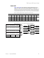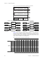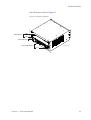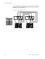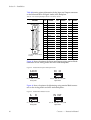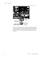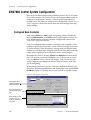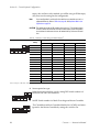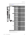
1
Concerto
ROUTING MATRIX
Instruction Manual
SOFTWARE VERSION 1.7.5
071813809
APRIL 2008
Affiliate with the N.V. KEMA in The Netherlands
CERTIFICATE
Certificate Number: 510040.001
The Quality System of:
Grass Valley, Inc.
400 Providence Mine Road
Nevada City, CA 95945
United States
15655 SW Greystone Ct.
Beaverton, OR 97006
United States
10 Presidential Way
rd
3 Floor, Suite 300
Woburn, MA 01801
United States
Nederland B.V.
4800 RP BREDA
The Netherlands
Weiterstadt, Germany
Brunnenweg 9
D-64331 Weiterstadt
Germany
Rennes, France
Rue du Clos Courtel
Cesson-Sevigne, Cedex
France
Technopole Brest Iroise
CS 73808
29238 Brest Cedex 3
France
17 rue du Petit Albi-BP 8244
95801 Cergy Pontoise
Cergy, France
2300 South Decker Lake Blvd.
Salt Lake City, UT 84119
United States
7140 Baymeadows Way
Suite 101
Jacksonville, FL 32256
United States
Including its implementation, meets the requirements of the standard:
ISO 9001:2000
Scope:
The design, manufacture and support of video hardware and software products and
related systems.
This Certificate is valid until:
This Certificate is valid as of:
Certified for the first time:
June 14, 2009
August 30, 2006
June 14, 2000
H. Pierre Sallé
President
KEMA-Registered Quality
The method of operation for quality certification is defined in the KEMA General Terms
And Conditions For Quality And Environmental Management Systems Certifications.
Integral publication of this certificate is allowed.
KEMA-Registered Quality, Inc.
4377 County Line Road
Chalfont, PA 18914
Ph: (215)997-4519
Fax: (215)997-3809
CRT 001 073004
Accredited By:
ANAB
Concerto
ROUTING MATRIX
Instruction Manual
SOFTWARE VERSION 1.7.5
071813809
APRIL 2008
Contacting Grass Valley
International
France +800 8080 2020 or +33 1 48 25 20 20 United States/Canada
Support Centers 24 x 7 +800 8080 2020 or +33 1 48 25 20 20
24 x 7
Asia
+1 800 547 8949 or +1 530 478 4148
Hong Kong, Taiwan, Korea, Macau: +852 2531 3058 Indian Subcontinent: +91 22 24933476
Southeast Asia/Malaysia: +603 7805 3884 Southeast Asia/Singapore: +65 6379 1313
China: +861 0660 159 450 Japan: +81 3 5484 6868
Local Support
Central/South America: +55 11 5509 3443
Australia and New Zealand: +61 1300 721 495
Centers
(available
Middle East: +971 4 299 64 40 Near East and Africa: +800 8080 2020 or +33 1 48 25 20 20
during normal
Belarus, Russia, Tadzikistan, Ukraine, Uzbekistan: +7 095 2580924 225 Switzerland: +41 1 487 80 02
business hours)
S. Europe/Italy-Roma: +39 06 87 20 35 28 -Milan: +39 02 48 41 46 58 S. Europe/Spain: +34 91 512 03 50
Europe
Benelux/Belgium: +32 (0) 2 334 90 30 Benelux/Netherlands: +31 (0) 35 62 38 42 1 N. Europe: +45 45 96 88 70
Germany, Austria, Eastern Europe: +49 6150 104 444 UK, Ireland, Israel: +44 118 923 0499
Copyright © Thomson. All rights reserved.
This product may be covered by one or more U.S. and foreign patents.
Grass Valley Web Site
The www.thomsongrassvalley.com web site offers the following:
Online User Documentation — Current versions of product catalogs, brochures,
data sheets, ordering guides, planning guides, manuals, and release notes
in .pdf format can be downloaded.
FAQ Database — Solutions to problems and troubleshooting efforts can be
found by searching our Frequently Asked Questions (FAQ) database.
Software Downloads — Download software updates, drivers, and patches.
4
Concerto — Instruction Manual
Contents
Preface. . . . . . . . . . . . . . . . . . . . . . . . . . . . . . . . . . . . . . . . . . . . . . . . . . . . . . . . . . . . . . . . . . . . .
9
About This Manual . . . . . . . . . . . . . . . . . . . . . . . . . . . . . . . . . . . . . . . . . . . . . . . . . . . . . 9
Additional Documentation . . . . . . . . . . . . . . . . . . . . . . . . . . . . . . . . . . . . . . . . . . . . 9
Safety Summary
Safety Terms and Symbols. . . . . . . . . . . . . . . . . . . . . . . . . . . . . . . . . . . . . . . . . . . . . .
Terms in This Manual . . . . . . . . . . . . . . . . . . . . . . . . . . . . . . . . . . . . . . . . . . . . . . . .
Terms on the Product . . . . . . . . . . . . . . . . . . . . . . . . . . . . . . . . . . . . . . . . . . . . . . . .
Symbols on the Product . . . . . . . . . . . . . . . . . . . . . . . . . . . . . . . . . . . . . . . . . . . . . .
Warnings . . . . . . . . . . . . . . . . . . . . . . . . . . . . . . . . . . . . . . . . . . . . . . . . . . . . . . . . . . . .
Cautions . . . . . . . . . . . . . . . . . . . . . . . . . . . . . . . . . . . . . . . . . . . . . . . . . . . . . . . . . . . . .
11
11
11
12
12
13
Regulatory Notices
Certifications and Compliances . . . . . . . . . . . . . . . . . . . . . . . . . . . . . . . . . . . . . . . . .
FCC Emission Control . . . . . . . . . . . . . . . . . . . . . . . . . . . . . . . . . . . . . . . . . . . . . . .
Canadian EMC Notice of Compliance . . . . . . . . . . . . . . . . . . . . . . . . . . . . . . . . . .
EN55022 Class A Warning . . . . . . . . . . . . . . . . . . . . . . . . . . . . . . . . . . . . . . . . . . . .
Canadian Certified Power Cords . . . . . . . . . . . . . . . . . . . . . . . . . . . . . . . . . . . . . .
Canadian Certified AC Adapter . . . . . . . . . . . . . . . . . . . . . . . . . . . . . . . . . . . . . . .
Laser Compliance . . . . . . . . . . . . . . . . . . . . . . . . . . . . . . . . . . . . . . . . . . . . . . . . . . .
Laser Safety Requirements . . . . . . . . . . . . . . . . . . . . . . . . . . . . . . . . . . . . . . . . . .
Laser Safety . . . . . . . . . . . . . . . . . . . . . . . . . . . . . . . . . . . . . . . . . . . . . . . . . . . . . . .
FCC Emission Limits . . . . . . . . . . . . . . . . . . . . . . . . . . . . . . . . . . . . . . . . . . . . . . .
Certification . . . . . . . . . . . . . . . . . . . . . . . . . . . . . . . . . . . . . . . . . . . . . . . . . . . . . . . .
15
15
15
15
16
16
16
16
16
17
17
Section 1 — System Description . . . . . . . . . . . . . . . . . . . . . . . . . . . . . . . . . . . . . . .
19
Mixed Module Matrices . . . . . . . . . . . . . . . . . . . . . . . . . . . . . . . . . . . . . . . . . . . . . . . .
Controller Module Identification . . . . . . . . . . . . . . . . . . . . . . . . . . . . . . . . . . . . . . . .
Module Configuration . . . . . . . . . . . . . . . . . . . . . . . . . . . . . . . . . . . . . . . . . . . . . . . . .
Module Identification . . . . . . . . . . . . . . . . . . . . . . . . . . . . . . . . . . . . . . . . . . . . . . . . . .
Optimum Matrix Configurations . . . . . . . . . . . . . . . . . . . . . . . . . . . . . . . . . . . . . . . .
7 RU Concerto / 8 RU Concerto+ Frames . . . . . . . . . . . . . . . . . . . . . . . . . . . . . . . . .
32x32 / 96x96 . . . . . . . . . . . . . . . . . . . . . . . . . . . . . . . . . . . . . . . . . . . . . . . . . . . . .
64x64 / 64x64 . . . . . . . . . . . . . . . . . . . . . . . . . . . . . . . . . . . . . . . . . . . . . . . . . . . . .
96x96 / 32x32 . . . . . . . . . . . . . . . . . . . . . . . . . . . . . . . . . . . . . . . . . . . . . . . . . . . . .
128x128 . . . . . . . . . . . . . . . . . . . . . . . . . . . . . . . . . . . . . . . . . . . . . . . . . . . . . . . . . .
32x32 / 32x32 / 64x64 . . . . . . . . . . . . . . . . . . . . . . . . . . . . . . . . . . . . . . . . . . . . . .
64x64 / 32x32 / 32x32 . . . . . . . . . . . . . . . . . . . . . . . . . . . . . . . . . . . . . . . . . . . . . .
32x32 / 64x64 / 32x32 . . . . . . . . . . . . . . . . . . . . . . . . . . . . . . . . . . . . . . . . . . . . . .
32x32 / 32x32 / 32x32 / 32x32 . . . . . . . . . . . . . . . . . . . . . . . . . . . . . . . . . . . . . . .
4 RU Frame. . . . . . . . . . . . . . . . . . . . . . . . . . . . . . . . . . . . . . . . . . . . . . . . . . . . . . . . . . .
64x64 . . . . . . . . . . . . . . . . . . . . . . . . . . . . . . . . . . . . . . . . . . . . . . . . . . . . . . . . . . . .
32x32 / 32x32 . . . . . . . . . . . . . . . . . . . . . . . . . . . . . . . . . . . . . . . . . . . . . . . . . . . . .
TDM Expansion. . . . . . . . . . . . . . . . . . . . . . . . . . . . . . . . . . . . . . . . . . . . . . . . . . . . . . .
TDM: 256x256 . . . . . . . . . . . . . . . . . . . . . . . . . . . . . . . . . . . . . . . . . . . . . . . . . . . . .
20
20
22
23
26
27
27
29
31
32
35
37
38
40
42
42
43
45
45
Concerto — Instruction Manual
5
Contents
TDM: 224x224 / 32x32 . . . . . . . . . . . . . . . . . . . . . . . . . . . . . . . . . . . . . . . . . . . . .
TDM: 192x192 / 64x64 . . . . . . . . . . . . . . . . . . . . . . . . . . . . . . . . . . . . . . . . . . . . .
TDM: 160x160 / 96x96 . . . . . . . . . . . . . . . . . . . . . . . . . . . . . . . . . . . . . . . . . . . . .
Monitor Output Configuration . . . . . . . . . . . . . . . . . . . . . . . . . . . . . . . . . . . . . . . . .
Analog Video Monitor Configuration . . . . . . . . . . . . . . . . . . . . . . . . . . . . . . . .
Digital Video Monitor Configuration . . . . . . . . . . . . . . . . . . . . . . . . . . . . . . . .
Audio Monitor Configuration. . . . . . . . . . . . . . . . . . . . . . . . . . . . . . . . . . . . . . .
Expanded Audio Monitor Configuration (7 RU and 8 RU Frames) . . . . . . .
47
50
52
55
55
55
56
59
Section 2 — Installation . . . . . . . . . . . . . . . . . . . . . . . . . . . . . . . . . . . . . . . . . . . . . . . .
65
Frame Installation. . . . . . . . . . . . . . . . . . . . . . . . . . . . . . . . . . . . . . . . . . . . . . . . . . . . .
Rear Support Bracket . . . . . . . . . . . . . . . . . . . . . . . . . . . . . . . . . . . . . . . . . . . . . . . .
Module Installation . . . . . . . . . . . . . . . . . . . . . . . . . . . . . . . . . . . . . . . . . . . . . . . . . . .
Cabling . . . . . . . . . . . . . . . . . . . . . . . . . . . . . . . . . . . . . . . . . . . . . . . . . . . . . . . . . . . . . .
Backplane Cabling . . . . . . . . . . . . . . . . . . . . . . . . . . . . . . . . . . . . . . . . . . . . . . . . . .
Expansion Audio System Cabling . . . . . . . . . . . . . . . . . . . . . . . . . . . . . . . . . . . . .
Pinouts . . . . . . . . . . . . . . . . . . . . . . . . . . . . . . . . . . . . . . . . . . . . . . . . . . . . . . . . . . . .
Frame Control Connectors. . . . . . . . . . . . . . . . . . . . . . . . . . . . . . . . . . . . . . . . . .
Matrix Backplane Connectors . . . . . . . . . . . . . . . . . . . . . . . . . . . . . . . . . . . . . . .
Crosspoint Bus Communications . . . . . . . . . . . . . . . . . . . . . . . . . . . . . . . . . . . . . .
Ethernet Communications. . . . . . . . . . . . . . . . . . . . . . . . . . . . . . . . . . . . . . . . . . . .
References . . . . . . . . . . . . . . . . . . . . . . . . . . . . . . . . . . . . . . . . . . . . . . . . . . . . . . . . .
Monitor Cabling . . . . . . . . . . . . . . . . . . . . . . . . . . . . . . . . . . . . . . . . . . . . . . . . . . . .
Analog Video Monitoring . . . . . . . . . . . . . . . . . . . . . . . . . . . . . . . . . . . . . . . . . .
Digital Video Monitoring. . . . . . . . . . . . . . . . . . . . . . . . . . . . . . . . . . . . . . . . . . .
Audio Monitoring . . . . . . . . . . . . . . . . . . . . . . . . . . . . . . . . . . . . . . . . . . . . . . . . .
Expanded Audio System Monitoring . . . . . . . . . . . . . . . . . . . . . . . . . . . . . . . .
Power . . . . . . . . . . . . . . . . . . . . . . . . . . . . . . . . . . . . . . . . . . . . . . . . . . . . . . . . . . . . . . .
AC Connections . . . . . . . . . . . . . . . . . . . . . . . . . . . . . . . . . . . . . . . . . . . . . . . . . . . .
48 VDC Connections . . . . . . . . . . . . . . . . . . . . . . . . . . . . . . . . . . . . . . . . . . . . . . . .
Option Installation . . . . . . . . . . . . . . . . . . . . . . . . . . . . . . . . . . . . . . . . . . . . . . . . . . . .
Expansion TDM Submodule Installation . . . . . . . . . . . . . . . . . . . . . . . . . . . . . . .
65
67
68
70
71
75
77
77
78
81
83
83
85
85
85
86
87
89
89
89
91
91
Section 3 — Control System Configuration . . . . . . . . . . . . . . . . . . . . . . . . . . . .
93
Controllers . . . . . . . . . . . . . . . . . . . . . . . . . . . . . . . . . . . . . . . . . . . . . . . . . . . . . . . . . . . 93
Control Mode/In Sel Setting. . . . . . . . . . . . . . . . . . . . . . . . . . . . . . . . . . . . . . . . . . 93
Ethernet Interface Configuration . . . . . . . . . . . . . . . . . . . . . . . . . . . . . . . . . . . . . . . . 94
Preparation . . . . . . . . . . . . . . . . . . . . . . . . . . . . . . . . . . . . . . . . . . . . . . . . . . . . . . . . 94
IP Address Setting Using NetConfig . . . . . . . . . . . . . . . . . . . . . . . . . . . . . . . . . . . 95
IP Address Setting Using Concerto Web Pages . . . . . . . . . . . . . . . . . . . . . . . . . . 97
Software Updates . . . . . . . . . . . . . . . . . . . . . . . . . . . . . . . . . . . . . . . . . . . . . . . . . . . 98
Concerto Web Pages . . . . . . . . . . . . . . . . . . . . . . . . . . . . . . . . . . . . . . . . . . . . . . . . . . 99
Matrix Controller System Configuration . . . . . . . . . . . . . . . . . . . . . . . . . . . . . . 100
Matrix Reference Configuration . . . . . . . . . . . . . . . . . . . . . . . . . . . . . . . . . . . . . . 101
Matrix Controller Factory Defaults . . . . . . . . . . . . . . . . . . . . . . . . . . . . . . . . . . . 102
Concerto Matrix Local Configuration . . . . . . . . . . . . . . . . . . . . . . . . . . . . . . . . . 103
Concerto Matrix Applications. . . . . . . . . . . . . . . . . . . . . . . . . . . . . . . . . . . . . . . . 104
System Maintenance. . . . . . . . . . . . . . . . . . . . . . . . . . . . . . . . . . . . . . . . . . . . . . . . 105
SMS7000 Control System Configuration . . . . . . . . . . . . . . . . . . . . . . . . . . . . . . . . 106
Configured Node Controller. . . . . . . . . . . . . . . . . . . . . . . . . . . . . . . . . . . . . . . . . 106
AES Attributes . . . . . . . . . . . . . . . . . . . . . . . . . . . . . . . . . . . . . . . . . . . . . . . . . . . . . . 108
AES Output Attributes. . . . . . . . . . . . . . . . . . . . . . . . . . . . . . . . . . . . . . . . . . . . . . 108
6
Concerto — Instruction Manual
Contents
AES Input Attributes. . . . . . . . . . . . . . . . . . . . . . . . . . . . . . . . . . . . . . . . . . . . . . . .
Encore Control System Configuration . . . . . . . . . . . . . . . . . . . . . . . . . . . . . . . . . . .
Jupiter Crosspoint Bus Controller Configuration . . . . . . . . . . . . . . . . . . . . . . . . .
Crosspoint Bus Controller Settings. . . . . . . . . . . . . . . . . . . . . . . . . . . . . . . . . . . .
CRS-MC-C2 Configuration. . . . . . . . . . . . . . . . . . . . . . . . . . . . . . . . . . . . . . . . .
Native Protocol Configuration . . . . . . . . . . . . . . . . . . . . . . . . . . . . . . . . . . . . . . . . .
Local Configuration Example . . . . . . . . . . . . . . . . . . . . . . . . . . . . . . . . . . . . . . . .
109
111
113
113
114
120
121
Section 4 — Maintenance and Troubleshooting. . . . . . . . . . . . . . . . . . . . . .
123
Field Replaceable Units . . . . . . . . . . . . . . . . . . . . . . . . . . . . . . . . . . . . . . . . . . . . . . .
Modules . . . . . . . . . . . . . . . . . . . . . . . . . . . . . . . . . . . . . . . . . . . . . . . . . . . . . . . . . .
To Remove Modules . . . . . . . . . . . . . . . . . . . . . . . . . . . . . . . . . . . . . . . . . . . . . .
To Insert Modules . . . . . . . . . . . . . . . . . . . . . . . . . . . . . . . . . . . . . . . . . . . . . . . .
Air Filter (7 RU Frame only) . . . . . . . . . . . . . . . . . . . . . . . . . . . . . . . . . . . . . . . . .
Fan Assembly . . . . . . . . . . . . . . . . . . . . . . . . . . . . . . . . . . . . . . . . . . . . . . . . . . . . . .
To Replace a Fan Assembly . . . . . . . . . . . . . . . . . . . . . . . . . . . . . . . . . . . . . . . .
Controller Modules . . . . . . . . . . . . . . . . . . . . . . . . . . . . . . . . . . . . . . . . . . . . . . . . .
Swapping a MCS-MC-C2 with a MCS-MC-C2 . . . . . . . . . . . . . . . . . . . . . . . .
Port Modules . . . . . . . . . . . . . . . . . . . . . . . . . . . . . . . . . . . . . . . . . . . . . . . . . . . . . .
Audio and SD Video Module Modifications. . . . . . . . . . . . . . . . . . . . . . . . . . . .
HD Video Module and Rear Panel Modifications . . . . . . . . . . . . . . . . . . . . . . .
Digital Audio Balanced Backplane Transformers . . . . . . . . . . . . . . . . . . . . . . .
Service and Replacement Parts . . . . . . . . . . . . . . . . . . . . . . . . . . . . . . . . . . . . . . . . .
Troubleshooting . . . . . . . . . . . . . . . . . . . . . . . . . . . . . . . . . . . . . . . . . . . . . . . . . . . . .
Matrix Controller LEDs . . . . . . . . . . . . . . . . . . . . . . . . . . . . . . . . . . . . . . . . . . . . .
Matrix Module LEDs. . . . . . . . . . . . . . . . . . . . . . . . . . . . . . . . . . . . . . . . . . . . . . . .
TDM Submodule LEDs. . . . . . . . . . . . . . . . . . . . . . . . . . . . . . . . . . . . . . . . . . . . . .
Power Supply Modules . . . . . . . . . . . . . . . . . . . . . . . . . . . . . . . . . . . . . . . . . . . . .
4 and 7 RU frames . . . . . . . . . . . . . . . . . . . . . . . . . . . . . . . . . . . . . . . . . . . . . . . .
8 RU frame . . . . . . . . . . . . . . . . . . . . . . . . . . . . . . . . . . . . . . . . . . . . . . . . . . . . . .
123
123
123
123
124
124
124
125
125
129
129
130
130
131
131
131
136
136
138
138
138
Appendix A — Specifications . . . . . . . . . . . . . . . . . . . . . . . . . . . . . . . . . . . . . . . . . .
139
Performance and Environmental Specifications . . . . . . . . . . . . . . . . . . . . . . . . . .
Concerto Routing Matrix . . . . . . . . . . . . . . . . . . . . . . . . . . . . . . . . . . . . . . . . . . . .
Analog Video . . . . . . . . . . . . . . . . . . . . . . . . . . . . . . . . . . . . . . . . . . . . . . . . . . . . . .
SD and HD Digital Video . . . . . . . . . . . . . . . . . . . . . . . . . . . . . . . . . . . . . . . . . . . .
Analog Audio. . . . . . . . . . . . . . . . . . . . . . . . . . . . . . . . . . . . . . . . . . . . . . . . . . . . . .
Digital Audio AES . . . . . . . . . . . . . . . . . . . . . . . . . . . . . . . . . . . . . . . . . . . . . . . . . .
TimeCode and Port . . . . . . . . . . . . . . . . . . . . . . . . . . . . . . . . . . . . . . . . . . . . . . . . .
Mechanical and Power Specifications . . . . . . . . . . . . . . . . . . . . . . . . . . . . . . . . . . .
139
139
139
140
142
143
144
144
Appendix B — Reference Tables . . . . . . . . . . . . . . . . . . . . . . . . . . . . . . . . . . . . . .
145
Physical Level Table . . . . . . . . . . . . . . . . . . . . . . . . . . . . . . . . . . . . . . . . . . . . . . . . . . 145
Glossary . . . . . . . . . . . . . . . . . . . . . . . . . . . . . . . . . . . . . . . . . . . . . . . . . . . . . . . . . . . . . . . . .
149
Index . . . . . . . . . . . . . . . . . . . . . . . . . . . . . . . . . . . . . . . . . . . . . . . . . . . . . . . . . . . . . . . . . . . . .
159
Concerto — Instruction Manual
7
Contents
8
Concerto — Instruction Manual
Preface
About This Manual
This manual provides installation, operation, and service information specific to the Concerto Multi-Format Router.
Additional Documentation
The Concerto Multi-Format Router can be controlled by the Encore, Jupiter,
or SMS Series 7000 Control Systems. Configuration information required
for using the Concerto with a control system is contained in the control
system’s documentation set. Concerto specific information is contained in
this manual.
Electronic copies of all routing documentation is available on the documentation CD that came with your frame. A printed copy of the documentation
set was provided with the system. Individual manuals may be ordered by
contacting Technical Support.
For assistance and to access the current documentation that is available on
our web site, see Contacting Grass Valley on page 4.
Concerto — Instruction Manual
9
Preface
10
Concerto — Instruction Manual
Safety Summary
Read and follow the important safety information below, noting especially
those instructions related to risk of fire, electric shock or injury to persons.
Additional specific warnings not listed here may be found throughout the
manual.
WARNING Any instructions in this manual that require opening the equipment cover
or enclosure are for use by qualified service personnel only. To reduce the
risk of electric shock, do not perform any servicing other than that contained in the operating instructions unless you are qualified to do so.
Safety Terms and Symbols
Terms in This Manual
Safety-related statements may appear in this manual in the following form:
WARNING Warning statements identify conditions or practices that may result in personal injury or loss of life.
CAUTION Caution statements identify conditions or practices that may result in damage
to equipment or other property, or which may cause equipment crucial to
your business environment to become temporarily non-operational.
Terms on the Product
The following terms may appear on the product:
DANGER — A personal injury hazard is immediately accessible as you read
the marking.
WARNING — A personal injury hazard exists but is not immediately acces-
sible as you read the marking.
CAUTION — A hazard to property, product, and other equipment is present.
Concerto — Instruction Manual
11
Safety Summary
Symbols on the Product
The following symbols may appear on the product:
Indicates that dangerous high voltage is present within the
equipment enclosure that may be of sufficient magnitude to
constitute a risk of electric shock.
Indicates that user, operator or service technician should refer
to product manual(s) for important operating, maintenance,
or service instructions.
This is a prompt to note fuse rating when replacing fuse(s).
The fuse referenced in the text must be replaced with one
having the ratings indicated.
Identifies a protective grounding terminal which must be connected to earth ground prior to making any other equipment
connections.
Identifies an external protective grounding terminal which
may be connected to earth ground as a supplement to an
internal grounding terminal.
Indicates that static sensitive components are present which
may be damaged by electrostatic discharge. Use anti-static
procedures, equipment and surfaces during servicing.
Warnings
The following warning statements identify conditions or practices that can
result in personal injury or loss of life.
Dangerous voltage or current may be present — Disconnect power and remove
battery (if applicable) before removing protective panels, soldering, or
replacing components.
Do not service alone — Do not internally service this product unless another
person capable of rendering first aid and resuscitation is present.
Remove jewelry — Prior to servicing, remove jewelry such as rings, watches,
and other metallic objects.
Avoid exposed circuitry — Do not touch exposed connections, components or
circuitry when power is present.
12
Concerto — Instruction Manual
Safety Summary
Use proper power cord — Use only the power cord supplied or specified for
this product.
Ground product — Connect the grounding conductor of the power cord to
earth ground.
Operate only with covers and enclosure panels in place — Do not operate this
product when covers or enclosure panels are removed.
Use correct fuse — Use only the fuse type and rating specified for this
product.
Use only in dry environment — Do not operate in wet or damp conditions.
Use only in non-explosive environment — Do not operate this product in an
explosive atmosphere.
High leakage current may be present — Earth connection of product is essential
before connecting power.
Dual power supplies may be present — Be certain to plug each power supply
cord into a separate branch circuit employing a separate service ground.
Disconnect both power supply cords prior to servicing.
Double pole neutral fusing — Disconnect mains power prior to servicing.
Use proper lift points — Do not use door latches to lift or move equipment.
Avoid mechanical hazards — Allow all rotating devices to come to a stop before
servicing.
Cautions
The following caution statements identify conditions or practices that can
result in damage to equipment or other property
Use correct power source — Do not operate this product from a power source
that applies more than the voltage specified for the product.
Use correct voltage setting — If this product lacks auto-ranging power sup-
plies, before applying power ensure that the each power supply is set to
match the power source.
Provide proper ventilation — To prevent product overheating, provide equip-
ment ventilation in accordance with installation instructions.
Use anti-static procedures — Static sensitive components are present which
may be damaged by electrostatic discharge. Use anti-static procedures,
equipment and surfaces during servicing.
Concerto — Instruction Manual
13
Safety Summary
Do not operate with suspected equipment failure — If you suspect product damage
or equipment failure, have the equipment inspected by qualified service
personnel.
Ensure mains disconnect — If mains switch is not provided, the power cord(s)
of this equipment provide the means of disconnection. The socket outlet
must be installed near the equipment and must be easily accessible. Verify
that all mains power is disconnected before installing or removing power
supplies and/or options.
Route cable properly — Route power cords and other cables so that they ar not
likely to be damaged. Properly support heavy cable bundles to avoid connector damage.
Use correct power supply cords — Power cords for this equipment, if provided,
meet all North American electrical codes. Operation of this equipment at
voltages exceeding 130 VAC requires power supply cords which comply
with NEMA configurations. International power cords, if provided, have
the approval of the country of use.
Use correct replacement battery — This product may contain batteries. To
reduce the risk of explosion, check polarity and replace only with the same
or equivalent type recommended by manufacturer. Dispose of used batteries according to the manufacturer’s instructions.
Troubleshoot only to board level — Circuit boards in this product are densely
populated with surface mount technology (SMT) components and application specific integrated circuits (ASICS). As a result, circuit board repair at
the component level is very difficult in the field, if not impossible. For warranty compliance, do not troubleshoot systems beyond the board level.
14
Concerto — Instruction Manual
Regulatory Notices
Certifications and Compliances
FCC Emission Control
This equipment has been tested and found to comply with the limits for a
Class A digital device, pursuant to Part 15 of the FCC Rules. These limits
are designed to provide reasonable protection against harmful interference
when the equipment is operated in a commercial environment. This equipment generates, uses, and can radiate radio frequency energy and, if not
installed and used in accordance with the instruction manual, may cause
harmful interference to radio communications. Operation of this equipment in a residential area is likely to cause harmful interference in which
case the user will be required to correct the interference at his own expense.
Changes or modifications not expressly approved by Grass Valley Group
can affect emission compliance and could void the user’s authority to
operate this equipment.
Canadian EMC Notice of Compliance
This digital apparatus does not exceed the Class A limits for radio noise
emissions from digital apparatus set out in the Radio Interference Regulations of the Canadian Department of Communications.
Le présent appareil numérique n’emet pas de bruits radioélectriques
dépassant les limites applicables aux appareils numeriques de la classe A
préscrites dans le Règlement sur le brouillage radioélectrique édicte par le
ministère des Communications du Canada.
EN55022 Class A Warning
For products that comply with Class A. In a domestic environment this
product may cause radio interference in which case the user may be
required to take adequate measures.
Concerto — Instruction Manual
15
Regulatory Notices
Canadian Certified Power Cords
Canadian approval includes the products and power cords appropriate for
use in the North America power network. All other power cords supplied
are approved for the country of use.
Canadian Certified AC Adapter
Canadian approval includes the AC adapters appropriate for use in the
North America power network. All other AC adapters supplied are
approved for the country of use.
Laser Compliance
Laser Safety Requirements
The device used in this product is a Class 1 certified laser product. Operating this product outside specifications or altering from its original design
may result in hazardous radiation exposure, and may be considered an act
of modifying or new manufacturing of a laser product under U.S. regulations contained in 21CFR Chapter1, subchapter J or CENELEC regulations
in HD 482 S1. People performing such an act are required by law to recertify
and reidentify this product in accordance with provisions of 21CFR subchapter J for distribution within the U.S.A., and in accordance with
CENELEC HD 482 S1 for distribution within countries using the IEC 825
standard.
Laser Safety
Laser safety in the United States is regulated by the Center for Devices and
Radiological Health (CDRH). The laser safety regulations are published in
the “Laser Product Performance Standard,” Code of Federal Regulation
(CFR), Title 21, Subchapter J.
The international Electrotechnical Commission (IEC) Standard 825, “Radiation of Laser Products, Equipment Classification, Requirements and
User’s Guide,” governs laser products outside the United States. Europe
and member nations of the European Free trade Association fall under the
jurisdiction of the Comite European de Normalization Electrotechnique
(CENELEC).
For the CDRH: The radiant power is detected trough a 7 mm aperture at a
distance of 200 mm from the source focused through a lens with a focal
length of 100 mm.
For IEC compliance: The radiant power is detected trough a 7 mm aperture
at a distance of 100 mm from the source focused through a lens with a focal
length of 100 mm.
16
Concerto — Instruction Manual
Regulatory Notices
FCC Emission Limits
This device complies with Part 15 of the FCC Rules. Operation is subject to
the following two conditions: (1) This device may not cause harmful interference, and (2) this device must accept any interference received,
including interference that may cause undesirable operation. This device
has been tested and found to comply with FCC Part 15 Class B limits for a
digital device when tested with a representative laser-based fiber optical
system that complies with ANSI X3T11 Fiber Channel Standard.
Certification
Category Standard
Designed/tested for compliance with:
Safety
UL1950
Safety of Information Technology Equipment, including Electrical Business Equipment (Second edition, 1993).
IEC 950
Safety of Information Technology Equipment, including Electrical Business Equipment (Second edition, 1991).
CAN/CSA C22.2, No. 950-93
Safety of Information Technology Equipment, including Electrical Business Equipment.
EN60950
Safety of Information Technology Equipment, including Electrical Business Equipment.
Concerto — Instruction Manual
17
Regulatory Notices
18
Concerto — Instruction Manual
Section
1
System Description
The Concerto Multi-Format Router is a matrix-type video/audio/data
switching system designed for use in broadcast, teleproduction, and networking facilities.
The module slots in the frame are not format sensitive. The slots are physically configured by plugging in any Concerto module and associated
backplane into any slot. Each module is a complete 32x32 matrix containing
inputs, outputs, and crosspoints. By inserting the modules in the frame in
different configurations, such as two digital video modules in adjoining
slots, matrices of 32x32 to 128x128 are created.
CAUTION If a module is plugged into an incompatible backplane it will cause damage.
Three rack frame versions are available:
•
4 RU Concerto frame with two slots for modules. This chassis, which is
sometimes referred to as the “Concerto 64” frame, can use the lower
cost 64x32 modules.
•
7 RU Concerto frame with four slots for modules. This frame can be
loaded with any four modules, with the exceptions that only two HD
video modules can be installed when there are two other modules; or if
three HD video modules are installed then the fourth slot must be left
empty.
•
8 RU Concerto+ frame with four slots for modules. This frame can be
loaded with any combination of four modules including four HD video
modules.
Module signal formats include:
•
Analog (audio and video),
•
Digital (AES audio, SD video, and HD video1), and
•
Data (TimeCode and Port) modules.
Two video reference inputs, allow assignment of both PAL and NTSC references to the same frame.
The frame is equipped with a 48 VDC external power connector.
1. For
a discussion of recent modifications to the HD video module and rear panel, see page 130.
Concerto — Instruction Manual
19
Section 1 — System Description
Mixed Module Matrices
The Analog Audio module has Analog to Digital and Digital to Analog
converters built into the module. This allows the configuration of physical
matrices that contain Analog Audio modules and Digital Audio modules.
These mixed audio matrices work the same as regular matrices with all
inputs available to all outputs.
When configuring a level or matrix that contains both Analog Audio
modules and AES Digital Audio modules use settings for AES Digital
Audio for all the modules in the grouping.
The Digital Video modules SD and HD can be combined into a physical
matrix. All SD video signals can be routed through either module making
SD video available to all inputs and outputs. The HD signal (1.485 Gbps)
can only be routed through the HD module.
CAUTION The maximum number of HD modules that can be in a 7 RU Concerto frame
is three in which case the fourth slot has to remain empty. If two HD modules
are used then the other two slots can be loaded with any of the non HD modules.
When configuring a level or matrix that contains both SD and HD Digital
Video modules use settings for SD Digital Video for all the modules in the
grouping. The Analog Video module can not be mixed with Digital Video
modules in the same level but can be in the same frame as a separate level.
The Port module can be used as either a TimeCode module or a Port
module. TimeCode and Port cannot be mixed in the same level.
Controller Module Identification
Controller (CM) modules are designed to work in pairs (one primary, one
backup) to provide failure resistance. The primary CM provides all
required functions; the backup is ready to take over should the primary
unit fail. Control logic facilitates the orderly change of control between the
two modules and ensures that only one module at a time controls the
external serial busses.
Control consists of the messages created and sent to the CM to set matrix
crosspoints, and the return messages from the CM containing true tally
status back to the control system.
The CMs can be inserted into a powered frame. To ensure that the system
power supply is not disturbed, a pre-charge resistor is connected in series
with one of the rear connector pins. The corresponding pin on the backplane connector is longer than any of the other power pins. This allows the
pre-charge pin to make connection before the others.
20
Concerto — Instruction Manual
Controller Module Identification
Vertical interval reference is required for crosspoint switching tasks. This is
an analog video input which can be NTSC or PAL. This input is processed
to extract vertical sync and odd/even field (if any) information. A predefined programmable logic device (PLD) is used to create a switching
strobe that is offset into line 10 for NTSC or line 6 for PAL. A video presence
detector interrupts the processor if the video reference is missing. If this reference is missing a fake sync is generated at a default asynchronous
interval.
Concerto has three Controller modules. Two of the modules are Ethernet
only. One Ethernet Controller is labeled CRS2001 CONTROLLER 671-6381-xx
with an Ethernet interface of10Base-T and the other is labeled CRS2001 FAST
CONTROLLER 671-6434-xx with an Ethernet interface of 10/100Base-T. The
third Controller is labeled CRS-MC-C2 671-6495-xx and can be set to allow
either Ethernet or Crosspoint Bus interface control. Do not mix Controller
types in a single matrix. See Figure 1 for help in identifying Controllers.
Figure 1. Controller Module Identification
GRASS VALLEY GROUP
CRS2001 FAST CONTROLLER
671-6434 –
GRASS VALLEY GROUP
CRS2001 CONTROLLER
671-6381 –
MADE
MADE
IN
U.S.A.
GRASS VALLEY GROUP
CRS-MC-C2
MADE
A_LEVEL
1 2 3 4 5 6 7 8
D_LEVEL
RECV
VI 2
PRES
1 2 3 4 5 6 7 8
ON
ON
ACT
SYNC
ERR
1 2 3 4 5 6 7 8
+2.5V
LINK
B_OPTIONS
D_OPTIONS
CONFIG
1 2 3 4 5 6 7 8
S13
S11
1 2 3 4 5 6 7 8
ON
DONE
RESET
CLEAR MEM
PWR
OK
48K
PRES
MODE/IN
SEL
M A T R I X MAP
BUSY
TC2
PRES
S12
ON
ON
TC1
PRES
XMIT ERROR
1 2 3 4 5 6 7 8
VI 1
PRES
A
B
C
D
E
F
G
H
C_OPTIONS
ON
ON
TX
+3.3V
B_LEVEL
A
B
C
D
E
F
G
H
671-6495
C_LEVEL
1 2 3 4 5 6 7 8
RX
1 2 3 4 5 6 7 8
+5V
COL
GND
A_OPTIONS
U.S.A.
U.S.A.
ON
ON
FAST
1 2 3 4 5 6 7 8
A
B
C
D
E
F
G
H
A
B
C
D
E
F
G
H
IN
IN
8138_02_65R2
Concerto — Instruction Manual
21
Section 1 — System Description
Module Configuration
Each module receives 32 inputs from the backplane associated with the slot
position of the module. Each module delivers 32 outputs to the backplane
associated with the slot position of the module. In Figure 2, the module in
slot position 1 (top position) is receiving Inputs 1-32 from the backplane in
slot position 1. Because Figure 2 shows a 128x128 matrix, Inputs 33-128 are
available to the module via the Interconnect module. The module can now
deliver any of the Sources connected to Inputs 1-128 to the Output connectors 1-32 on the backplane in slot position 1.
Figure 2. Block Diagram for Module in Slot 1 (Top) in 128x128 Matrix
32 Inputs
(1-32)
from Slot 1
backplane
Output
Reclocking
Input
Equalization
32 Inputs
(33-64)
from Matrix 2
32 Inputs
Input (1-32)
(65-96)
Distribution
from Matrix 3
to Slots
2, 3, & 4
32 Inputs
(97-128)
from Matrix 4
128x32
Crosspoint
Matrix
32x1
Monitor
Crosspoint
32 Outputs
(1-32)
to Slot 1
backplane
8138_00_62r0
The Analog Audio module has dual Inputs and Outputs to accommodate
the Left and Right channels. These dual connections are labelled on the
backplane using a 1A/1B format. The default is to software configure the
1A (Left) and 1B (Right) channels as a stereo signal. AES Audio has single
Inputs and Outputs where the default is to software configure each connector as a stereo signal.
The stereo channels can be configured to switch separately as mono signals.
The smallest mono matrix is a single module of 64x64 and the largest is
512x512 using two Concerto frames.
The module receives 64 inputs from the backplane associated with the slot
position of the module. Each module delivers 64 outputs to the backplane
associated with the slot position of the module. In Figure 3, the module in
slot position 1 is receiving Inputs 1A/1B-32A/32B from the backplane in
slot position 1. Because Figure 3 shows a 256x256 matrix, Inputs 33A/33B128A/128B are available to the module via the Interconnect module. The
module can now deliver any of the Sources connected to Inputs 1A/1B128A/128B to the Output connectors 1A/1B-32A/32B on the backplane in
slot position 1.
22
Concerto — Instruction Manual
Module Identification
Figure 3. Block Diagram for Module in Slot 1 in Analog Audio Mono 256x256 Matrix
64 Inputs
(1A/1B to
32A/32B)
from Slot 1
backplane
D to A
Converter
A to D
Converter
64 Inputs
(33A/33B to 64A/64B)
from Matrix 2
Time
Division
Multiplexing
256x64
64 Inputs
(65A/65B to 96A/96B)
from Matrix 3
64 Inputs
(97A/97B to 128A/128B)
from Matrix 4
64x1
Monitor
Crosspoint
64 Outputs
(1A/1B to
32A/32B)
to Slot 1
backplane
8138_00_63r0
Input (1A/1B to
32A/32B) Distribution
to Slots 2, 3, & 4
Module Identification
The modules have either a 128x32, 64x32, or a 32x32 Crosspoint configuration. The 64x32 Crosspoint configuration will allow two modules to create
a 64x64 matrix but will not allow larger matrices. The 64x32 Crosspoint
modules can only be used in slots 1 (top) and 2 or slots 3 and 4 of the 7 RU
Concerto or 8 RU Concerto+ frames to create 64x64 matrices. The 32x32
Crosspoint configuration modules cannot be combined into larger matrices
but can be used in all of the Concerto frames. The Analog audio matrices
also have three Maximum Input Level specifications +24 dBu, +18 dBu, and
+15 dBu. The attributes of each module are identified by the last two digits
of the part number.
Table 1 identifies Analog video modules.
Table 1. Analog Video Modules 671-6369-##
## Range
00-49
Matrix Size
4
96x96
3
64x64
2
32x32
50-79
80-99
Modules
128x128
64x64
1
a
2
32x32
1
32x32
1
a
If a 7 RU Concerto or 8 RU Concerto+ frame is used to create this matrix the modules
must be placed in slots 1 and 2 or slots 3 and 4
Concerto — Instruction Manual
23
Section 1 — System Description
Table 2 identifies SD digital video modules.
Table 2. SD Digital Video Modules 671-6372-##
## Range
Matrix Size
00-49
Modules
128x128
4
96x96
3
64x64
2
32x32
50-79
64x64
80-99
1
a
2
32x32
1
32x32
1
a
If a 7 RU Concerto or 8 RU Concerto+ frame is used to create this matrix the modules
must be placed in slots 1 and 2 or slots 3 and 4
Table 3 identifies HD digital video modules.
Table 3. HD Video Modules 691-0072-##
## Range
00-49
50-79
80-99
Matrix Size
Modules
Comments
128x128
4
Must use the 128x128 Concerto+ frame for this matrix.
96x96
3
If 128x128 Concerto frame is used for this matrix the fourth slot has
to remain empty.,
64x64
2
-
32x32
1
-
64x64a
2
-
32x32
1
-
32x32
1
-
a If
a 7 RU Concerto or 8 RU Concerto+ frame is used to create this matrix the modules must be placed in slots 1 and 2 or
slots 3 and 4
Table 5 identifies AES digital audio modules.
Table 4. AES Digital Audio Modules 671-6371-##
## Range
00-49
Matrix Size
128x128
4
96x96
3
64x64
2
32x32
50-79
80-99
Modules
64x64
1
a
2
32x32
1
32x32
1
a
If a 7 RU Concerto or 8 RU Concerto+ frame is used to create this matrix the modules
must be placed in slots 1 and 2 or slots 3 and 4
24
Concerto — Instruction Manual
Module Identification
Table 5 identifies Analog audio modules.
Table 5. Analog Audio Modules 671-6370-##
## Range
00-24
25-49
50-60
Maximum dBu Level
+24 dBu
+18 dBu
+15 dBu
Matrix Size
4
96x96
3
64x64
2
32x32
1
128x128
4
96x96
3
64x64
2
32x32
1
128x128
4
96x96
3
64x64
2
32x32
61-70
+24 dBu
71-80
+18 dBu
81-90
+24 dBu
91-99
+18 dBu
Modules
128x128
64x64
1
a
2
32x32
1
64x64a
2
32x32
1
32x32
1
32x32
1
a
If a 7 RU Concerto or 8 RU Concerto+ frame is used to create this matrix the modules must be placed in slots 1 and 2 or
slots 3 and 4
Concerto — Instruction Manual
25
Section 1 — System Description
Optimum Matrix Configurations
Optimum performance is achieved by positioning the modules in the
frame using the top to bottom priority shown in Table 6.
Note
This hierarchy is required for interfacing to Jupiter Control Systems.
Table 6. Top-to-bottom Module Positions
Module
Abbreviation
Analog Video
AV
Digital Video (SD or HD)
DV
Analog Audio
AA
Digital Audio (AES)
DA
Data (TimeCode or Port)
TCP
CAUTION The maximum number of HD modules that can be in a 7 RU Concerto frame
is three in which case the fourth slot has to remain empty. If two HD modules
are used then the other two slots can be loaded with any of the non HD modules.
Note
Because the 8 RU Concerto+ frame provides additional power and cooling
capacity when compared to the 7 RU frame, there are no restrictions on the
number of HD video modules in 8 RU frames.
The following are general guidelines:
26
•
Empty slots need to be identified for their future use, such as HD Video,
•
All modules that are in the same level must be next to each other in the
frame,
•
The preferred hierarchy between SD and HD Video modules in the
same frame is to place the SD modules before the HD modules. If you
have a frame with two SD modules and two HD modules, place the SD
modules in slots 1 (top) and 2, and the HD modules in slots 3 and 4, and
•
There is no preferred hierarchy between TimeCode and Port modules
in the same frame.
Concerto — Instruction Manual
7 RU Concerto / 8 RU Concerto+ Frames
7 RU Concerto / 8 RU Concerto+ Frames
32x32 / 96x96
Table 7 and Figure 4 show optimum module placement options for creating
a single module 32x32 matrix and a three module 96x96 matrix. In Option
1, you can use 3 SD Video modules or a combination of 1 or 2 HD Video
modules with SD Video modules. There are four variations shown (options
11 to 14) for a 96x96 matrix using mixed audio. Option 6 uses all audio
modules but the inputs and outputs of the two types of audio are kept separate. In Figure 4 the Analog to Digital and Digital to Analog converters are
shown in the mixed audio matrices. Additional combinations can be
created using mixed audio, or mixed video, or mixed data modules.
Table 7. Examples of Optimum Configurations (32x32 and 96x96)
One 32x32 Matrix and One 96x96 Matrix
a
a
Slot
Position
Option 1
Modules
Option 2
Modules
Option 3
Modules
Option 4
Modules
Option 5
Modules
Option 6
Modules
Option 7
Modules
Matrix
Size
1
AV
AV
AV
AV
DV
DV
DV
32x32
2
DV
AA
DA
TCP
AA
DA
TCP
3
DV
AA
DA
TCP
AA
DA
TCP
4
DV
AA
DA
TCP
AA
DA
TCP
96x96
For this option 1 or 2 HD video modules can be used with SD video modules to create a 96x96 Digital Video matrix.
One 32x32 Matrix and One 96x96 Matrix
Slot
Position
Option 8
Modules
Option 9
Modules
Option 10
Modules
Option 11
Modules
Option 12
Modules
Option 13
Modules
Option 14
Modules
Matrix
Size
32x32
1
AA
AA
DA
AV
DV
AV
DV
2
DA
TCP
TCP
AA
AA
AA
AA
3
DA
TCP
TCP
AA
AA
DA
DA
4
DA
TCP
TCP
DA
DA
DA
DA
Concerto — Instruction Manual
96x96
27
Section 1 — System Description
Figure 4. One 32x32 and One 96x96 Module Configuration and Signal Flow
Input 1-32
Xpt (In=1-32, Out=1-32)
Output 1-32
Input 1-32
Xpt (In=1-96, Out=1-32)
Output 1-32
Xpt (In=1-96, Out=33-64)
Input 65-96
Xpt (In=1-96, Out=65-96)
Controller 1
Controller 2
Power
Supply 2
Output 33-64
Signal Flow for Options 1 to 10
96x96
Matrix
Inputs 1-32
Xpt (In=1-32,
Out=1-32)
Outputs 1-32
Inputs 1-32
Xpt (In=1-96,
Out=1-32)
Outputs 1-32
Inputs 33-64
Xpt (In=1-96,
Out=33-64)
Outputs 33-64
Inputs 65-96
Xpt (In=1-96,
Out=65-96)
Outputs 65-96
Output 65-96
8138_00_37r0
Input 33-64
32x32
Matrix
Power
Supply 1
Signal Flow for Options 13 and 14
Signal Flow for Options 11 and 12
Xpt (In=1-32,
Out=1-32)
Inputs 1-32
A to D Conv.
Xpt (In=1-96,
Out=1-32)
Xpt (In=1-32,
Out=1-32)
Inputs 1-32
Outputs 1-32
D to A Conv.
Inputs 1-32
8138_00_45r0
Inputs 1-32
Outputs 1-32
D to A Conv.
Xpt (In=1-96,
Out=1-32)
Outputs 1-32
A to D Conv.
Inputs 33-64
A to D Conv.
Outputs 33-64
Xpt (In=1-96,
Out=65-96)
Inputs 65-96
Outputs 1-32
D to A Conv.
Xpt (In=1-96,
Out=33-64)
Outputs 65-96
Inputs 33-64
Xpt (In=1-96,
Out=33-64)
Outputs 33-64
Inputs 65-96
Xpt (In=1-96,
Out=65-96)
Outputs 65-96
8138_00_48r0
8138_00_46r0
Table 8 shows the Jupiter interface settings. Options 11 to 14 use mixed
modules AA and DA to create a 96x96 matrix level that is set as AES audio.
The numbers shown for the DIP switch banks indicate which of the eight
switches should be set in the On position.
Table 8. Rotary and DIP Switch Settings for Jupiter Interface
Jupiter Settings for Options from Table 7
1
3
4
5
6
7
8
9
10
11
12
13
14
Rotary S12
1
1
1
1
1
1
1
1
1
1
1
1
1
1
Rotary S13
0
3
3
7
3
3
7
4
A
A
3
3
3
3
A_LEVEL
1
1
1
1
1, 2, 3
1, 2, 3
1, 2, 3
2
2
6
1
1, 2, 3
1
1, 2, 3
A_OPTIONS
Switch
2
B_LEVEL
B_OPTIONS
C_LEVEL
C_OPTIONS
D_LEVEL
D_OPTIONS
-
-
-
-
-
-
-
-
-
-
-
-
-
-
1, 2, 3
2
6
5
2
6
1, 2
6
5
1, 2
6
6
6
6
-
-
-
-
-
-
1
-
-
1
-
-
-
-
1, 2, 3
2
6
5
2
6
1, 2
6
5
1, 2
6
6
6
6
-
-
-
-
-
-
1
-
-
1
-
-
-
-
1, 2, 3
2
6
5
2
6
1, 2
6
5
1, 2
6
6
6
6
-
-
-
-
-
-
1
-
-
1
-
-
-
-
DIP Switches set to ON Position
28
Concerto — Instruction Manual
7 RU Concerto / 8 RU Concerto+ Frames
64x64 / 64x64
Table 9 and Figure 5 show optimum module placement options for creating
a pair of two module 64x64 matrices.There are two variations shown
(options 5, and 9) for a lower 64x64 matrix using mixed audio. Option 9
uses all audio modules but the inputs and outputs of the two types of audio
are kept separate. In Figure 5 the Analog to Digital and Digital to Analog
converters are shown in the mixed audio matrices. Additional combinations can be created using mixed audio, or mixed video, or mixed data
modules.
Table 9. Examples of Optimum Matrix Configurations (64x64 and 64x64)
Two 64x64 Matrices
Slot
Position
Option 1
Modules
Option 2
Modules
Option 3
Modules
Option 4
Modules
Option 5
Modules
Option 6
Modules
1
AV
AV
AV
AV
AV
DV
2
AV
AV
AV
AV
AV
DV
3
DV
AA
DA
TCP
AA
AA
4
DV
AA
DA
TCP
DA
AA
Option 10
Modules
Option 11
Modules
Matrix
Size
Matrix
Size
64x64
64x64
Two 64x64 Matrices
Slot
Position
Option 7
Modules
Option 8
Modules
Option 9
Modules
1
DV
DV
AA
AA
DA
2
DV
DV
AA
AA
DA
3
DA
TCP
DA
TCP
TCP
4
DA
TCP
DA
TCP
TCP
Concerto — Instruction Manual
64x64
64x64
29
Section 1 — System Description
Figure 5. Two 64x64 Module Configuration and Signal Flow
Input 1-32
Xpt (In=1-64, Out=1-32)
Output 1-32
64x64
Matrix
Input 33-64
Xpt (In=1-64, Out=33-64)
Output 33-64
Input 1-32
Xpt (In=1-64, Out=1-32)
Output 1-32
64x64
Matrix
Xpt (In=1-64, Out=33-64)
Controller 1
Power
Supply 2
Controller 2
Output 33-64
8138_00_33r0
Input 33-64
Power
Supply 1
Signal Flow for Options 1 to 4, and 6 to 11
Signal Flow for Option 5
Inputs 1-32
Xpt (In=1-64,
Out=1-32)
Outputs 1-32
Inputs 33-64
Xpt (In=1-64,
Out=33-64)
Outputs 33-64
Inputs 1-32
Xpt (In=1-64,
Out=1-32)
Outputs 1-32
Xpt (In=1-64,
Out=33-64)
Outputs 33-64
Xpt (In=1-64,
Out=1-32)
Inputs 1-32
Inputs 33-64
Outputs 1-32
Outputs 33-64
Xpt (In=1-64,
Out=33-64)
D to A Conv.
Inputs 1-32
Inputs 33-64
A to D Conv.
Xpt (In=1-64,
Out=1-32)
Outputs 1-32
Inputs 33-64
Xpt (In=1-64,
Out=33-64)
Outputs 33-64
8138_00_44r0
8138_00_49r0
Table 10 shows the Jupiter interface settings. Options 4, 10, and 11 show settings for Port modules, and Option 8 shows the settings for TimeCode. The
numbers shown for the DIP switch banks indicate which of the eight
switches should be set in the On position.
Table 10. Rotary and DIP Switch Settings for Jupiter Interface
Jupiter Settings for Options from Table 9
Switches
1
2
3
4
5
6
7
8
9
10
11
Rotary S12
2
2
2
2
2
2
2
2
2
2
2
Rotary S13
0
2
2
6
2
2
2
6
4
9
9
A_LEVEL
1
1
1
1
1
1, 2, 3
1, 2, 3
1, 2, 3
2
2
6
A_OPTIONS
-
-
-
-
-
-
-
-
-
-
-
B_LEVEL
1
1
1
1
1
1, 2, 3
1, 2, 3
1, 2, 3
2
2
6
B_OPTIONS
C_LEVEL
C_OPTIONS
D_LEVEL
D_OPTIONS
-
-
-
-
-
-
-
-
-
-
-
1, 2, 3
2
6
5
6
2
6
1, 2
6
5
5
-
-
-
-
-
-
-
1
-
-
-
1, 2, 3
2
6
5
6
2
6
1, 2
6
5
5
-
-
-
-
-
-
-
1
-
-
-
DIP Switches set to ON Position
30
Concerto — Instruction Manual
7 RU Concerto / 8 RU Concerto+ Frames
96x96 / 32x32
Table 11 and Figure 6 show optimum module placement options for creating a three module 96x96 matrix and a single module 32x32 matrix.
Options 5, 6, and 7, you can use 3 SD Video modules or a combination of 1
or 2 HD Video modules with SD Video modules. Additional combinations
can be created using mixed audio, or mixed video, or mixed data modules.
Table 11. Examples of Optimum Matrix Configurations (96x96 and 32x32)
One 96x96 Matrix and One 32x32 Matrix
Slot
Option 1 Option 2 Option 3 Option 4 Option 5a
Position Modules Modules Modules Modules Modules
a
Option 6a
Modules
Option 7a
Modules
Option 8 Option 9
Modules Modules
1
AV
AV
AV
AV
DV
DV
DV
AA
AA
2
AV
AV
AV
AV
DV
DV
DV
AA
AA
3
AV
AV
AV
AV
DV
DV
DV
AA
AA
4
DV
AA
DA
TCP
AA
DA
TCP
DA
TCP
Matrix
Size
96x96
32x32
For this option 1 or 2 HD video modules can be used with SD video modules to create a 96x96 Digital Video matrix.
Figure 6. One 96x96 and One 32x32 Module Configuration and Signal Flow
Signal Flow for Options 1 to 9
Xpt (In=1-96, Out=1-32)
Output 1-32
Input 33-64
Xpt (In=1-96, Out=33-64)
Output 33-64
Input 65-96
Xpt (In=1-96, Out=65-96)
Output 65-96
Input 1-32
Xpt (In=1-32, Out=1-32)
Output 1-32
Controller 1
Controller 2
Power
Supply 2
Concerto — Instruction Manual
Power
Supply 1
96x96
Matrix
32x32
Matrix
Inputs 1-32
Xpt (In=1-96,
Out=1-32)
Outputs 1-32
Inputs 33-64
Xpt (In=1-96,
Out=33-64)
Outputs 33-64
Inputs 65-96
Xpt (In=1-96,
Out=65-96)
Outputs 65-96
Inputs 1-32
Xpt (In=1-32,
Out=1-32)
Outputs 1-32
8138_00_54r0
8138_00_36r0
Input 1-32
31
Section 1 — System Description
Table 12 shows the Jupiter interface settings. Options 4 and 9 show settings
for Port modules, and Option 7 shows Timecode.The numbers shown for
the DIP switch banks indicate which of the eight switches should be set in
the On position.
Table 12. Rotary and DIP Switch Settings for Jupiter Interface
Jupiter Settings for Options from Table 11
Switches
1
2
3
4
5
6
7
8
9
Rotary S12
3
3
3
3
3
3
3
3
3
Rotary S13
0
1
1
5
1
1
5
4
8
A_LEVEL
1
1
1
1
1, 2, 3
1, 2, 3
1, 2, 3
2
2
A_OPTIONS
-
-
-
-
-
-
-
-
-
B_LEVEL
1
1
1
1
1, 2, 3
1, 2, 3
1, 2, 3
2
2
B_OPTIONS
-
-
-
-
-
-
-
-
-
C_LEVEL
1
1
1
1
1, 2, 3
1, 2, 3
1, 2, 3
2
2
C_OPTIONS
-
-
-
-
-
-
-
-
-
1, 2, 3
2
6
5
2
6
1, 2
6
5
-
-
-
-
-
-
1
-
-
D_LEVEL
D_OPTIONS
DIP Switches set to ON Position
128x128
Table 13 and Figure 7 show optimum module placement options for creating a single four module 128x128 matrix. There are three variations
shown (options 5 to 7) for a 128x128 matrix using mixed audio. In Figure 7
the Analog to Digital and Digital to Analog converters are shown in the
mixed audio matrices. Additional combinations can be created using
mixed audio, or mixed video, or mixed data modules.
Table 13. Examples of Optimum Matrix Configurations (128x128)
One 128x128 Matrix
a
Slot
Option 1 Option 2
Position Modules Modules
1
a
32
AV
DV
Option 3 Option 4 Option 5 Option 6 Option 7 Option 8b
Modules Modules Modules Modules Modules Modules
AA
DA
AA
AA
AA
TCP
Option 9c
Modules
Matrix
Size
TCP
2
AV
DV
AA
DA
AA
AA
DA
TCP
TCP
3
AV
DV
AA
DA
AA
DA
DA
TCP
TCP
4
AV
DV
AA
DA
DA
DA
DA
TCP
TCP
128x128
For this option 1 or 2 HD video modules can be used with SD video modules to create a 128x128 Digital Video matrix.
b
All modules are Timecode.
c
All modules are Port
Concerto — Instruction Manual
7 RU Concerto / 8 RU Concerto+ Frames
Figure 7. 128x128 Module Configuration and Signal Flow
Input 1-32
Xpt (In=1-128, Out=1-32)
Output 1-32
Input 33-64
Xpt (In=1-128, Out=33-64)
Output 33-64
128x128
Matrix
Xpt (In=1-128, Out=65-96)
Input 97-128
Xpt (In=1-128, Out=97-128) Output 97-128
Controller 1
Power
Supply 2
Controller 2
Output 65-96
Power
Supply 1
Signal Flow for Options 1 to 4, 8, 9
Signal Flow for Option 5
Inputs 1-32
Xpt (In=1-128,
Out=1-32)
Outputs 1-32
Inputs 33-64
Xpt (In=1-128,
Out=33-64)
Outputs 33-64
Inputs 65-96
Xpt (In=1-128,
Out=65-96)
Outputs 65-96
Inputs 97-128
Xpt (In=1-128,
Out=97-128)
Outputs 97-128
Inputs 1-32
8138_00_31r0
Input 65-96
A to D Conv.
Inputs 33-64
Xpt (In=1-128,
Out=1-32)
D to A Conv.
Xpt (In=1-128,
Out=33-64)
D to A Conv.
A to D Conv.
Inputs 65-96
A to D Conv.
8138_00_53r0
Inputs 97-128
Outputs 1-32
Outputs 33-64
Xpt (In=1-128,
Out=65-96)
Xpt (In=1-128,
Out=97-128)
D to A Conv.
Outputs 65-96
Outputs 97-128
8138_00_50r0
Signal Flow for Option 7
Signal Flow for Option 6
Inputs 1-32
Xpt (In=1-128,
Out=1-32)
A to D Conv.
Inputs 33-64
A to D Conv.
Inputs 65-96
Inputs 97-128
Xpt (In=1-128,
Out=33-64)
Xpt (In=1-128,
Out=65-96)
D to A Conv.
Inputs 1-32
Outputs 1-32
A to D Conv.
Concerto — Instruction Manual
Outputs 1-32
Inputs 33-64
Outputs 33-64
Outputs 97-128
8138_00_51r0
D to A Conv.
Xpt (In=1-128,
Out=33-64)
D to A Conv.
Outputs 65-96
Xpt (In=1-128,
Out=97-128)
Xpt (In=1-128,
Out=1-32)
Outputs 33-64
Inputs 65-96
Xpt (In=1-128,
Out=65-96)
Outputs 65-96
Inputs 97-128
Xpt (In=1-128,
Out=97-128)
Outputs 97-128
8138_00_52r0
33
Section 1 — System Description
Table 14 shows the Jupiter interface settings. Option 8 shows settings for
TimeCode modules, and Option 9 shows Port.The numbers shown for the
DIP switch banks indicate which of the eight switches should be set in the
On position.
Table 14. Rotary and DIP Switch Settings for Jupiter Interface
Jupiter Settings for Options from Table 13
Switches
1
2
3
4
5a
6a
7a
8b
9c
Rotary S12
0
0
0
0
0
0
0
0
0
Rotary S13
0
0
4
4
4
4
4
E
E
A_LEVEL
1
1, 2, 3
2
6
6
6
6
1, 2
5
A_OPTIONS
-
-
-
-
-
-
-
1
-
B_LEVEL
1
1, 2, 3
2
6
6
6
6
1, 2
5
B_OPTIONS
-
-
-
-
-
-
-
1
-
C_LEVEL
1
1, 2, 3
2
6
6
6
6
1, 2
5
C_OPTIONS
-
-
-
-
-
-
-
1
-
D_LEVEL
1
1, 2, 3
2
6
6
6
6
1, 2
5
D_OPTIONS
-
-
-
-
-
-
-
1
-
DIP Switches set to ON Position
a
Mixed Audio modules use AES Digital Audio as level.
b All modules TimeCode.
c All modules Port.
34
Concerto — Instruction Manual
7 RU Concerto / 8 RU Concerto+ Frames
32x32 / 32x32 / 64x64
Table 15 and Figure 8 show optimum module placement options for creating a two single module 32x32 matrices and a two module 64x64 matrix.
There is one variation shown (option4) for a 64x64 matrix using mixed
audio. In Figure 8 the Analog to Digital and Digital to Analog converters
are shown in the mixed audio matrices. Additional combinations can be
created using mixed audio, or mixed video, or mixed data modules.
Table 15. Examples of Optimum Matrix Configurations (32x32,32x32, and 64x64)
Two 32x32 Matrices and One 64x64 Matrix
Slot
Position
Option 1
Modules
Option 2
Modules
Option 3
Modules
Option 4
Modules
Option 5
Modules
Option 6
Modules
Matrix
Size
1
AV
AV
AV
AV
AV
AV
32x32
32x32
2
DV
DV
DV
DV
AA
AA
3
AA
DA
TCP
AA
DA
TCP
4
AA
DA
TCP
DA
DA
TCP
64x64
Two 32x32 Matrices and One 64x64 Matrix
Slot
Position
Option 7
Modules
Option 8
Modules
Option 9
Modules
Option 10
Modules
Option 11
Modules
Matrix
Size
1
AV
DV
DV
DV
AA
32x32
32x32
2
DA
AA
AA
DA
DA
3
TCP
DA
TCP
TCP
TCP
4
TCP
DA
TCP
TCP
TCP
Concerto — Instruction Manual
64x64
35
Section 1 — System Description
Figure 8. Two 32x32 and One 64x64 Module Configuration and Signal Flow
Input 1-32
Xpt (In=1-32, Out=1-32)
Output 1-32
32x32
Matrix
Input 1-32
Xpt (In=1-32, Out=1-32)
Output 1-32
32x32
Matrix
Input 1-32
Xpt (In=1-96, Out=1-32)
Output 1-32
64x64
Matrix
Xpt (In=1-96, Out=33-64)
Controller 1
Power
Supply 2
Controller 2
Output 33-64
8138_00_38r0
Input 33-64
Power
Supply 1
Signal Flow for Options 1 to 3, 5 to 11
Signal Flow for Option 4
Inputs 1-32
Xpt (In=1-32,
Out=1-32)
Outputs 1-32
Inputs 1-32
Xpt (In=1-32,
Out=1-32)
Outputs 1-32
Inputs 1-32
Xpt (In=1-32,
Out=1-32)
Outputs 1-32
Inputs 1-32
Xpt (In=1-32,
Out=1-32)
Outputs 1-32
Inputs 1-32
Xpt (In=1-64,
Out=1-32)
Outputs 1-32
Xpt (In=1-64,
Out=33-64)
Outputs 33-64
Inputs 33-64
Inputs 1-32
D to A Conv.
Xpt (In=1-64,
Out=1-32)
A to D Conv.
Outputs 1-32
Xpt (In=1-64,
Out=33-64)
Inputs 33-64
8138_00_56r0
Outputs 33-64
8138_00_55r0
Table 16 shows the Jupiter interface settings. Options 3, 6, 10, and 11 show
settings for Port modules, and Options 7 and 9 show the settings for TimeCode. The numbers shown for the DIP switch banks indicate which of the
eight switches should be set in the On position.
Table 16. Rotary and DIP Switch Settings for Jupiter Interface
Jupiter Settings for Options from Table 15
1
2
3
4
5
6
7
8
9
10
11
Rotary S12
4
4
4
4
4
4
4
4
4
4
4
Rotary S13
2
2
6
2
3
D
D
3
D
D
9
A_LEVEL
1
1
1
1
1
1
1
1, 2, 3
1, 2, 3
1, 2, 3
2
A_OPTIONS
Switches
-
-
-
-
-
-
-
-
-
-
-
1, 2, 3
1, 2, 3
1, 2, 3
1, 2, 3
2
2
6
2
2
6
6
B_OPTIONS
-
-
-
-
-
-
-
-
-
-
-
C_LEVEL
2
6
5
2
6
5
1, 2
6
1, 2
5
5
C_OPTIONS
-
-
-
-
-
-
1
-
1
-
-
D_LEVEL
2
6
5
6
6
5
1, 2
6
1, 2
5
5
D_OPTIONS
-
-
-
-
-
-
1
-
1
-
-
B_LEVEL
DIP Switches set to ON Position
36
Concerto — Instruction Manual
7 RU Concerto / 8 RU Concerto+ Frames
64x64 / 32x32 / 32x32
Table 17 and Figure 9 show optimum module placement options for creating a two module 64x64 matrix and two single module 32x32 matrices.
Additional combinations can be created using mixed audio, or mixed
video, or mixed data modules.
Table 17. Examples of Optimum Matrix Configurations (64x64, 32x32, and 32x32)
One 64x64 Matrix and Two 32x32 Matrices
Slot
Option 1 Option 2 Option 3 Option 4 Option 5 Option 6 Option 7 Option 8 Option 9
Position Modules Modules Modules Modules Modules Modules Modules Modules Modules
Matrix
Size
1
AV
AV
AV
AV
AV
DV
DV
DV
AA
2
AV
AV
AV
AV
AV
DV
DV
DV
AA
3
DV
DV
DV
AA
AA
AA
AA
DA
DA
32x32
4
AA
DA
TCP
DA
TCP
DA
TCP
TCP
TCP
32x32
64x64
Figure 9. One 64x64 and Two 32x32 Module Configuration and Signal Flow
Input 1-32
Xpt (In=1-96, Out=1-32)
Output 1-32
Signal Flow for Options 1 to 9
64x64
Matrix
Input 1-32
Input 1-32
Controller 1
Controller 2
Xpt (In=1-96, Out=33-64)
Xpt (In=1-32, Out=1-32)
Xpt (In=1-32, Out=1-32)
Power
Supply 2
Output 33-64
Output 1-32
Output 1-32
Power
Supply 1
32x32
Matrix
Inputs 1-32
Xpt (In=1-64,
Out=1-32)
Outputs 1-32
Inputs 33-64
Xpt (In=1-64,
Out=33-64)
Outputs 33-64
Inputs 1-32
Xpt (In=1-32,
Out=1-32)
Outputs 1-32
Inputs 1-32
Xpt (In=1-32,
Out=1-32)
Outputs 1-32
32x32
Matrix
8138_00_39r0
Input 33-64
8138_00_57r0
Table 18 shows the Jupiter interface settings. Options 3, 7, and 18 show settings for Port modules, and Options 5 and 9 show the settings for Time-
Concerto — Instruction Manual
37
Section 1 — System Description
Code. The numbers shown for the DIP switch banks indicate which of the
eight switches should be set in the On position.
Table 18. Rotary and DIP Switch Settings for Jupiter Interface
Jupiter Settings for Options from Table 17
Switches
1
2
3
4
5
6
7
8
9
Rotary S12
5
5
5
5
5
5
5
5
5
Rotary S13
1
1
5
2
B
2
B
B
8
A_LEVEL
1
1
1
1
1
1, 2, 3
1, 2, 3
1, 2, 3
2
A_OPTIONS
-
-
-
-
-
-
-
-
-
B_LEVEL
1
1
1
1
1
1, 2, 3
1, 2, 3
1, 2, 3
2
B_OPTIONS
C_LEVEL
-
-
-
-
-
-
-
-
-
1, 2, 3
1, 2, 3
1, 2, 3
2
2
2
2
6
6
C_OPTIONS
-
-
-
-
-
-
-
-
-
D_LEVEL
2
6
5
6
1, 2
6
5
5
1, 2
D_OPTIONS
-
-
-
-
1
-
-
-
1
DIP Switches set to ON Position
32x32 / 64x64 / 32x32
Table 19 and Figure 10 show optimum module placement options for creating a single modules 32x32 matrix, a two module 64x64 matrix and a
second single module 32x32 matrix. 64x32 Video modules cannot be used
in slots 2 and 3 to create a 64x64 matrix. Use 128x32 Video modules for these
configurations. Additional combinations can be created using mixed
audio, or mixed video, or mixed data modules.
Table 19. Examples of Optimum Matrix Configurations (32x32,64x64, and 32x32)
One 32x32 Matrix, One 64x64 Matrix, & One 32x32 Matrix Options 1 to 6
Slot
Position
Option 1
Modules
Option 2
Modules
Option 3
Modules
Option 4
Modules
Option 5
Modules
Option 6
Modules
Matrix
Size
32x32
1
AV
AV
AV
AV
AV
AV
2
DV
DV
DV
AA
AA
AA
3
DV
DV
DV
AA
AA
DA
4
AA
DA
TCP
DA
TCP
TCP
64x64
32x32
One 32x32 Matrix, One 64x64 Matrix, & One 32x32 Matrix Options 7 to 12
Slot
Position
38
Option 7
Modules
Option8
Modules
Option 9
Modules
Option 10
Modules
Option 11
Modules
Option 12
Modules
Matrix
Size
32x32
1
AV
DV
DV
DV
DV
AA
2
DA
AA
AA
AA
DA
DA
3
DA
AA
AA
DA
DA
DA
4
TCP
DA
TCP
TCP
TCP
TCP
64x64
32x32
Concerto — Instruction Manual
7 RU Concerto / 8 RU Concerto+ Frames
Figure 10. One 32x32, One 64x64 and One 32x32 Module Configuration and Signal Flow
Input 1-32
Xpt (In=1-32, Out=1-32)
Output 1-32
Input 1-32
Xpt (In=1-96, Out=1-32)
Output 1-32
32x32
Matrix
Signal Flow for Options 1 to 12
64x64
Matrix
Input 1-32
Controller 1
Controller 2
Xpt (In=1-96, Out=33-64)
Xpt (In=1-32,
Out=1-32)
Outputs 1-32
Inputs 1-32
Xpt (In=1-64,
Out=1-32)
Outputs 1-32
Inputs 33-64
Xpt (In=1-64,
Out=33-64)
Outputs 33-64
Inputs 1-32
Xpt (In=1-32,
Out=1-32)
Outputs 1-32
Output 33-64
Xpt (In=1-32, Out=1-32)
Output 1-32
Power
Supply 2
32x32
Matrix
8138_00_35r0
Input 33-64
Inputs 1-32
Power
Supply 1
8138_00_58r0
Table 20 shows the Jupiter interface settings. Options 3, 5, 6, 9, 11, and 12
show settings for Port modules, and Options 7and 10 show Timecode.The
numbers shown for the DIP switch banks indicate which of the eight
switches should be set in the On position.
Table 20. Rotary and DIP Switch Settings for Jupiter Interface
Jupiter Settings for Options from Table 19
Switches
1
2
3
4
5
6
7
8
9
10
11
12
Rotary S12
6
6
6
6
6
6
6
6
6
6
6
6
Rotary S13
1
1
5
3
C
C
C
3
C
C
C
8
A_LEVEL
1
1
1
1
1
1
1
1, 2, 3
1, 2, 3
1, 2, 3
1, 2, 3
2
A_OPTIONS
-
-
-
-
-
-
-
-
-
-
-
-
1, 2, 3
1, 2, 3
1, 2, 3
2
2
6
6
2
2
6
6
6
-
-
-
-
-
-
-
-
-
-
-
-
1, 2, 3
1, 2, 3
1, 2, 3
2
2
6
6
2
2
6
6
6
B_LEVEL
B_OPTIONS
C_LEVEL
C_OPTIONS
-
-
-
-
-
-
-
-
-
-
-
-
D_LEVEL
2
6
5
6
5
5
1, 2
6
5
1, 2
5
5
D_OPTIONS
-
-
-
-
-
-
1
-
-
1
-
-
DIP Switches set to ON Position
Concerto — Instruction Manual
39
Section 1 — System Description
32x32 / 32x32 / 32x32 / 32x32
Table 21 and Figure 11 shows the optimum module placement for creating
four single module 32x32 matrices. Additional combinations are created
using mixed audio, or mixed video, or mixed data modules.
Table 21. Examples of Optimum Matrix Configurations (32x32, 32x32, 32x32, and 32x32)
Four 32x32 Matrices
Slot
Option 1 Option 2 Option 3 Option 4 Option 5 Option 6 Option 7 Option 8 Option 9
Position Modules Modules Modules Modules Modules Modules Modules Modules Modules
1
AV
AV
DV
AV
AV
AV
DV
2
DV
3
AA
4
DA
DV
DV
AA
DV
DV
DV
DV
AA
DA
DV
DV
DV
AA
TCP
TCP
AA
DA
TCP
DA
TCP
Matrix
Size
AA
32x32
AA
DA
32x32
TCP
TCP
32x32
TCP
32x32
Figure 11. Four 32x32 Module Configuration and Signal Flow
Input 1-32
Xpt (In=1-32, Out=1-32)
Output 1-32
32x32
Matrix
Input 1-32
Xpt (In=1-32, Out=1-32)
Output 1-32
32x32
Matrix
Input 1-32
Controller 1
Controller 2
Xpt (In=1-32, Out=1-32)
Xpt (In=1-32, Out=1-32)
Power
Supply 2
Output 1-32
Output 1-32
Power
Supply 1
Inputs 1-32
Xpt (In=1-32,
Out=1-32)
Outputs 1-32
Inputs 1-32
Xpt (In=1-32,
Out=1-32)
Outputs 1-32
Inputs 1-32
Xpt (In=1-32,
Out=1-32)
Outputs 1-32
Inputs 1-32
Xpt (In=1-32,
Out=1-32)
Outputs 1-32
32x32
Matrix
32x32
Matrix
8138_00_34r0
Input 1-32
Signal Flow for Options 1 to 9
8138_00_59r0
Table 22 shows the Jupiter interface settings. Options 3 to 7 show settings
for SD Video and HD Video modules that are not combined. Options 8 and
9 show settings for matrices with both TimeCode and Port modules. The
40
Concerto — Instruction Manual
7 RU Concerto / 8 RU Concerto+ Frames
numbers shown for the DIP switch banks indicate which of the eight
switches should be set in the On position.
Table 22. Rotary and DIP Switch Settings for Jupiter Interface
Jupiter Settings for Options from Table 21
Switches
1
2
3
4
5
6
7
8
9
Rotary S12
7
7
7
7
7
7
7
7
7
Rotary S13
2
B
C
1
1
5
2
D
D
A_LEVEL
1
1
1, 2, 3
1
1
1
1, 2, 3
1, 4
2
A_OPTIONS
-
-
-
-
-
-
-
-
-
1, 2, 3
1, 2, 3
2
1, 2, 3
1, 2, 3
1, 2, 3
1, 2, 3
2
6
B_LEVEL
B_OPTIONS
-
-
-
-
-
-
-
-
-
C_LEVEL
2
2
6
1, 4
1, 4
1, 4
2
5
5
C_OPTIONS
-
-
-
-
-
-
-
-
-
D_LEVEL
6
5
5
2
6
5
6
1, 2
1, 2
D_OPTIONS
-
-
-
-
-
-
-
1
1
DIP Switches set to ON Position
Concerto — Instruction Manual
41
Section 1 — System Description
4 RU Frame
64x64
Table 23 and Figure 12 show optimum module placement options for creating a 64x64 matrix. Additional combinations can be created using mixed
audio, or mixed video, or mixed data modules.
Table 23. Examples of Optimum Matrix Configurations (64x64)
64x64 Matrices
Slot
Position
Option 1
Modules
Option 2
Modules
Option 3
Modules
Option 4
Modules
Option 5
Modules
Option 6
Modules
1
AV
DV
AA
DA
TCP
AA
2
AV
DV
AA
DA
TCP
DA
Matrix
Size
64x64
Figure 12. 64x64 Module Configuration and Signal Flow
Input 1-32
Xpt (In=1-64, Out=1-32)
Output 1-32
64x64
Matrix
Controller 1
Controller 2
Xpt (In=1-64, Out=33-64)
Power
Supply 2
Output 33-64
Power
Supply 1
8138_05_167r0
Input 33-64
Signal Flow for Options 1 to 5
Signal Flow for Option 6
D to A Conv.
Inputs 1-32
Inputs 1-32
Xpt (In=1-64,
Out=1-32)
Outputs 1-32
Inputs 33-64
Xpt (In=1-64,
Out=33-64)
Outputs 33-64
8138_05_169r0
A to D Conv.
Xpt (In=1-64,
Out=1-32)
Outputs 1-32
Inputs 33-64
Xpt (In=1-64,
Out=33-64)
Outputs 33-64
8138_05_168r0
Table 24 shows the Jupiter interface settings. Option 4 shows settings for
Port modules, and Option 2 shows the settings for SD video. The numbers
42
Concerto — Instruction Manual
4 RU Frame
shown for the DIP switch banks indicate which of the eight switches should
be set in the On position.
Table 24. Rotary and DIP Switch Settings for Jupiter Interface
Jupiter Settings for Options from Table 23
Switches
1
2
3
4
5
6
Rotary S12
2
2
2
2
2
2
Rotary S13
0
0
4
4
E
4
A_LEVEL
1
1, 2, 3
2
6
5
2
A_OPTIONS
-
-
-
-
-
-
B_LEVEL
1
1, 2, 3
2
6
5
2
B_OPTIONS
-
-
-
-
-
-
DIP Switches set to ON Position
32x32 / 32x32
Table 25 and Figure 13 shows the optimum module placement for creating
two single module 32x32 matrices. Additional combinations are created
using mixed audio, or mixed video, or mixed data modules.
Table 25. Examples of Optimum Matrix Configurations (32x32, 32x32, 32x32, and 32x32)
Four 32x32 Matrices
Slot
Option 1 Option 2 Option 3 Option 4 Option 5 Option 6 Option 7 Option 8 Option 9 Option 10
Position Modules Modules Modules Modules Modules Modules Modules Modules Modules Modules
Matrix
Size
1
AV
AV
AV
AV
DV
DV
DV
AA
AA
DA
32x32
2
DV
AA
DA
TCP
AA
DA
TCP
DA
TCP
TCP
32x32
Figure 13. Two 32x32 Module Configuration and Signal Flow
Xpt (In=1-32, Out=1-32)
Output 1-32
32x32
Matrix
Input 1-32
Xpt (In=1-32, Out=1-32)
Output 1-32
32x32
Matrix
Controller 1
Controller 2
Power
Supply 2
Power
Supply 1
Signal Flow for Options 1 to 10
8138_05_170r0
Input 1-32
Inputs 1-32
Xpt (In=1-32,
Out=1-32)
Outputs 1-32
Inputs 1-32
Xpt (In=1-32,
Out=1-32)
Outputs 1-32
8138_05_171r0
Table 26 shows the Jupiter interface settings. Options 4 to 7 show settings
for SD Video modules in slot 1. Option 1 shows settings for SD video
module in slot 2. Options 4, 7, 9, and 10 show settings for Port modules. The
Concerto — Instruction Manual
43
Section 1 — System Description
numbers shown for the DIP switch banks indicate which of the eight
switches should be set in the On position.
Table 26. Rotary and DIP Switch Settings for Jupiter Interface
Jupiter Settings for Options from Table 25
Switches
1
2
3
4
5
6
7
8
9
10
Rotary S12
7
7
7
7
7
7
7
7
7
7
Rotary S13
0
3
3
7
3
3
7
4
A
A
A_LEVEL
1
1
1
1
1, 2, 3
1, 2, 3
1, 2, 3
2
2
6
A_OPTIONS
-
-
-
-
-
-
-
-
-
-
1, 2, 3
2
6
5
2
6
5
6
5
5
-
-
-
-
-
-
-
-
-
-
B_LEVEL
B_OPTIONS
DIP Switches set to ON Position
44
Concerto — Instruction Manual
TDM Expansion
TDM Expansion
You can use any two Concerto frames to create larger Audio matrices. The
matrices can be either Stereo or Mono. A Time Division Multiplex (TDM)
submodule is attached to one of the Audio modules in each frame.
For matrices under Jupiter control, the slot position of the Audio modules
with the TDM submodules will depend on the architecture of the expansion frame. If you have put a Video module in slot 1 of the expansion frame
and the module in slot 2 is an Audio module, then the Audio modules with
the TDM submodules would go in slot 2 on both frames.
For matrices under Encore control the Audio modules with the TDM submodules have to be in slot 1 in both frames.
A few examples of supported architecture are shown.
TDM: 256x256
In this configuration all modules in both frames are Audio modules.
Figure 14 shows the Signal Flow of a 256x256 Stereo matrix.
Figure 14. 256x256 Signal Flow
Inputs 1-32
TDM
Outputs 1-64
Outputs 65-128
TDM
Inputs 1-64
Inputs 65-128
Inputs 129-192
Inputs 193-256
Outputs 129-192
Outputs 193-256
Xpt (In=1-128,
Out=1-32)
A to D Conv.
Inputs 33-64
Outputs 1-32
Xpt (In=1-128,
Out=33-64)
A to D Conv.
Inputs 65-96
A to D Conv.
Inputs 97-128
D to A Conv.
D to A Conv.
Outputs 33-64
Xpt (In=1-128,
Out=65-96)
Xpt (In=1-128,
Out=97-128)
D to A Conv.
Outputs 65-96
Outputs 97-128
Inputs 129-160
Xpt (In=129-256,
Out=129-160)
A to D Conv.
Inputs 161-192
Outputs 129-160
Xpt (In=129-256,
Out=161-192)
A to D Conv.
Inputs 193-224
A to D Conv.
Inputs 225-256
D to A Conv.
D to A Conv.
Outputs 161-192
Xpt (In=129-256,
Out=193-224)
Xpt (In=129-256,
Out=225-256)
D to A Conv.
Outputs 193-224
Outputs 225-256
8138_04_104r0
Concerto — Instruction Manual
45
Section 1 — System Description
Figure 15 shows the configuration of the two frames with a TDM submodule attached to the Audio modules in slot 1 of each frame.
Figure 15. 256x256 Audio
Input 1-32
Xpt (In=1-128, Out=1-32)
TDM
Output 1-32
TDM
Input 129-160
Xpt (In=129-256, Out=129-160)
Output 129-160
Input 33-64
Xpt (In=1-128, Out=33-64)
Output 33-64
Input 161-192
Xpt (In=129-256, Out=161-192)
Output 161-192
256x256
Matrix
Xpt (In=1-128, Out=65-96)
Output 65-96
Input 193-224
Xpt (In=129-256, Out=193-224)
Output 193-224
Input 97-128
Xpt (In=1-128, Out=97-128)
Output 97-128
Input 225-256
Xpt (In=129-256, Out=225-256)
Output 225-256
Controller 1
Controller 2
Power
Supply 2
Controller 1
Power
Supply 1
Power
Supply 2
Controller 2
8138_00_108
Input 65-96
Power
Supply 1
Figure 16 shows the Rotary and DIP switch settings on the CRS-MC-C2
Controller module for this configuration.
Figure 16. Switch Settings for 256x256
Base Frame
2
2, 3
D_LEVEL
6, 8
6, 8
D_OPTIONS
2
2, 3
MODE/IN
SEL
ON
CLEAR MEM
1 2 3 4 5 6 7 8
CONFIG
2
4
ON
1 2 3 4 5 6 7 8
D_LEVEL
1 2 3 4 5 6 7 8
ON
B_LEVEL
ON
ON
1 2 3 4 5 6 7 8
1 2 3 4 5 6 7 8
A
B
C
D
E
F
G
H
1 2 3 4 5 6 7 8
C_OPTIONS
ON
1 2 3 4 5 6 7 8
A_OPTIONS
ON
3 4 5
2
7
8
9
D C B
M A T R I X MAP
6
1
0
F
E
A
B
C
D
E
F
G
H
4
1 2 3 4 5 6 7 8
1 2 3 4 5 6 7 8
Expansion Frame
A
B
C
D
E
F
G
H
S11 MODE IN SEL
1 2 3 4 5 6 7 8
1 2 3 4 5 6 7 8
A
6
7
8
9
E
ON
3 4 5
1
0
F
D C B
A
ON
1 2 3 4 5 6 7 8
1 2 3 4 5 6 7 8
MODE/IN
SEL
C_OPTIONS
1 2 3 4 5 6 7 8
S13
6
ON
A
S11
6
ON
D C B
ON
S13
C_LEVEL
ON
7
8
9
E
S11
2, 3
S12
2
D_OPTIONS
B_OPTIONS
B_OPTIONS
6
1 2 3 4 5 6 7 8
6
A
B
C
D
E
F
G
H
6
1 2 3 4 5 6 7 8
3 4 5
1
0
F
A
ON
S12
B_LEVEL
1 2 3 4 5 6 7 8
D_OPTIONS
2, 3
ON
B_OPTIONS
2
ON
2
7
8
9
D C B
M A T R I X MAP
6
ON
CLEAR MEM
1 2 3 4 5 6 7 8
A
B
C
D
E
F
G
H
A_OPTIONS
ON
D_LEVEL
6
B_LEVEL
6
A
B
C
D
E
F
G
H
A_LEVEL
C_OPTIONS
4
A_OPTIONS
4
A
B
C
D
E
F
G
H
S13 MATRIX Map
3 4 5
1
0
F
E
C_LEVEL
0
A_LEVEL
0
2
A
B
C
D
E
F
G
H
DIP
Switch
Banks
S12 CONFIG
CONFIG
C_LEVEL
Rotary
Expansion
Frame
A_LEVEL
Switch
Base
Frame
8138_04_129r0
46
Concerto — Instruction Manual
TDM Expansion
TDM: 224x224 / 32x32
In this configuration one module in the expansion frame is not an Audio
module. Figure 17 shows the Signal Flow of a 224x224 and a 32x32 matrix.
The Signal Flow is independent of the slot positions in the expansion frame.
Figure 17. 224x224 and 32x32 Signal Flow
TDM
Outputs 1-64
Outputs 65-128
TDM
Inputs 1-64
Inputs 65-128
Inputs 129-192
Inputs 193-224
Outputs 129-192
Outputs 193-224
Inputs 1-32
Xpt (In=1-128,
Out=1-32)
D to A Conv.
A to D Conv.
Outputs 1-32
Xpt (In=1-128,
Out=33-64)
Inputs 33-64
A to D Conv.
D to A Conv.
Outputs 33-64
Xpt (In=1-128,
Out=65-96)
Inputs 65-96
A to D Conv.
Xpt (In=1-128,
Out=97-128)
Inputs 97-128
D to A Conv.
Outputs 65-96
Outputs 97-128
Inputs 129-160
Xpt (In=129-224,
Out=129-160)
A to D Conv.
D to A Conv.
Outputs 129-160
Xpt (In=129-224,
Out=161-192)
Inputs 161-192
A to D Conv.
D to A Conv.
Outputs 161-192
Xpt (In=129-224,
Out=193-224)
Inputs 193-224
A to D Conv.
D to A Conv.
Outputs 193-224
Xpt (In=1-32,
Out=1-32)
Inputs 1-32
Outputs 1-32
8138_04_105r0
Figure 18 shows the configuration of the two frames with a TDM submodule attached to the Audio modules in slot 1 of each frame. A Data
module is in slot 4 of the expansion frame.
Figure 18. 224x224 Audio and 32x32 Data
Xpt (In=1-128, Out=1-32)
TDM
Output 1-32
TDM
Input 129-160
Xpt (In=129-224, Out=129-160)
Output 129-160
Input 33-64
Xpt (In=1-128, Out=33-64)
Output 33-64
Input 161-192
Xpt (In=129-224, Out=161-192)
Output 161-192
Input 65-96
Xpt (In=1-128, Out=65-96)
Output 65-96
Input 193-224
Xpt (In=129-224, Out=193-224)
Output 193-224
Input 97-128
Xpt (In=1-128, Out=97-128)
Output 97-128
Input 1-32
Xpt (In=1-32, Out=1-32)
Output 1-32
Controller 1
Controller 2
Power
Supply 2
Concerto — Instruction Manual
Power
Supply 1
Controller 1
Controller 2
Power
Supply 2
Power
Supply 1
224x224
Matrix
32x32
Matrix
8138_00_118
Input 1-32
47
Section 1 — System Description
Figure 19 shows the Rotary and DIP switch settings on the CRS-MC-C2
Controller module for this configuration.
Figure 19. Switch Settings for 224x224 Audio and 32x32 Data
Base Frame
2
2, 3
C_LEVEL
6
6
C_OPTIONS
2
2, 3
D_LEVEL
6, 8
5a (or 1, 2) 8
D_OPTIONS
2
1b
S11 MODE IN SEL
4
ON
1 2 3 4 5 6 7 8
ON
1 2 3 4 5 6 7 8
ON
1 2 3 4 5 6 7 8
7
8
9
E
D C B
A
ON
1 2 3 4 5 6 7 8
1 2 3 4 5 6 7 8
MODE/IN
SEL
B_OPTIONS
1 2 3 4 5 6 7 8
S13
6
1 2 3 4 5 6 7 8
6
S11
6
1 2 3 4 5 6 7 8
A
ON
3 4 5
1
0
F
ON
CLEAR MEM
1 2 3 4 5 6 7 8
Expansion Frame
CONFIG
2
4
3 4 5
2
7
8
9
E
D C B
M A T R I X MAP
6
1
0
F
3 4 5
6
1
0
F
S13
B_LEVEL
S12
2, 3
ON
D_OPTIONS
2
ON
B_OPTIONS
A_OPTIONS
ON
2
7
8
9
D C B
M A T R I X MAP
6
A
B
C
D
E
F
G
H
6
S12
6
D_LEVEL
A_LEVEL
B_LEVEL
8
A
B
C
D
E
F
G
H
4
C_OPTIONS
S13 MATRIX Map
3 4 5
1
0
F
E
A_OPTIONS
3
A
B
C
D
E
F
G
H
0
2
C_LEVEL
DIP
Switch
Banks
S12 CONFIG
CONFIG
A_LEVEL
Rotary
Expansion
Frame
A
B
C
D
E
F
G
H
Switch
Base
Frame
A
7
8
9
E
D C B
A
1 2 3 4 5 6 7 8
1 2 3 4 5 6 7 8
1 2 3 4 5 6 7 8
MODE/IN
SEL
ON
S11
D_OPTIONS
B_OPTIONS
ON
1 2 3 4 5 6 7 8
ON
ON
CLEAR MEM
1 2 3 4 5 6 7 8
A
B
C
D
E
F
G
H
1 2 3 4 5 6 7 8
D_LEVEL
ON
B_LEVEL
C_OPTIONS
1 2 3 4 5 6 7 8
ON
A
B
C
D
E
F
G
H
1 2 3 4 5 6 7 8
A_OPTIONS
ON
1 2 3 4 5 6 7 8
ON
A
B
C
D
E
F
G
H
C_LEVEL
ON
A
B
C
D
E
F
G
H
b On for Timecode, Off for Port
A_LEVEL
a 5 = Port, 1 and 2 = Timecode
8138_04_130r0
48
Concerto — Instruction Manual
TDM Expansion
Jupiter Only Variation
Figure 20 shows the configuration of the two frames with a TDM submodule attached to the Audio modules in slot 2 of each frame. A Video
module is in slot 1 of the expansion frame.
Figure 20. 224x224 Audio and 32x32 Video Non Redundant
32x32
Matrix
Xpt (In=1-128, Out=1-32)
Output 1-32
Input 1-32
Xpt (In=1-32, Out=1-32)
Output 1-32
Input 33-64
Xpt (In=1-128, Out=33-64)
TDM
Output 33-64
TDM
Input 129-160
Xpt (In=129-224, Out=129-160)
Output 129-160
Input 65-96
Xpt (In=1-128, Out=65-96)
Output 65-96
Input 161-192
Xpt (In=129-224, Out=161-192)
Output 161-192
Input 97-128
Xpt (In=1-128, Out=97-128)
Output 97-128
Input 193-224
Xpt (In=129-224, Out=193-224)
Output 193-224
Controller 1
Controller 2
Power
Supply 2
Controller 1
Power
Supply 1
Power
Supply 2
Controller 2
224x224
Matrix
8138_00_120
Input 1-32
Power
Supply 1
Figure 21 shows the Rotary and DIP switch settings on the CRS-MC-C2
Controller module for this configuration.
Figure 21. Switch Settings for 224x224 Audio and 32x32 Video
Base Frame
2
2, 3
C_LEVEL
6
6
C_OPTIONS
2
2, 3
MODE/IN
SEL
S11
D_OPTIONS
S13
S12
1 2 3 4 5 6 7 8
ON
1 2 3 4 5 6 7 8
ON
ON
1 2 3 4 5 6 7 8
1 2 3 4 5 6 7 8
3 4 5
2
7
8
9
D C B
M A T R I X MAP
6
1
0
F
S12
1 2 3 4 5 6 7 8
ON
D_LEVEL
ON
1 2 3 4 5 6 7 8
Off for Reclocking, On for Forced Bypass
A
B
C
D
E
F
G
H
b
ON
B_LEVEL
a Off for Sync 1, On for Sync 2
A
B
C
D
E
F
G
H
4
C_OPTIONS
2, 3
4
CLEAR MEM
1 2 3 4 5 6 7 8
E
A_OPTIONS
2
S11 MODE IN SEL
1 2 3 4 5 6 7 8
ON
2
6, 8
D_OPTIONS
1 2 3 4 5 6 7 8
CONFIG
C_LEVEL
6, 8
1 2 3 4 5 6 7 8
ON
Expansion Frame
A_LEVEL
D_LEVEL
1 2 3 4 5 6 7 8
D C B
A
A
6
7
8
9
E
ON
3 4 5
1
0
F
D C B
A
ON
1 2 3 4 5 6 7 8
1 2 3 4 5 6 7 8
MODE/IN
SEL
B_OPTIONS
1 2 3 4 5 6 7 8
7
8
9
E
S13
6
ON
6
S11
6
ON
B_OPTIONS
B_LEVEL
ON
1 2 3 4 5 6 7 8
A
ON
3 4 5
1
0
F
A
B
C
D
E
F
G
H
1-4a, 5-8b
1 2 3 4 5 6 7 8
ON
D_OPTIONS
2
1 2 3 4 5 6 7 8
ON
B_OPTIONS
A_OPTIONS
ON
2
7
8
9
D C B
M A T R I X MAP
6
ON
CLEAR MEM
1 2 3 4 5 6 7 8
A
B
C
D
E
F
G
H
1 = Analog
1, 2, 3 = SD
1, 4 = HD
D_LEVEL
3
6
B_LEVEL
4
A_LEVEL
A
B
C
D
E
F
G
H
S13 MATRIX Map
A
B
C
D
E
F
G
H
DIP
Switch
Banks
C_OPTIONS
1
A_OPTIONS
0
3 4 5
1
0
F
E
A
B
C
D
E
F
G
H
S12 CONFIG
2
A
B
C
D
E
F
G
H
Rotary
CONFIG
C_LEVEL
Expansion
Frame
A_LEVEL
Base
Frame
Switch
8138_04_131r0
Concerto — Instruction Manual
49
Section 1 — System Description
TDM: 192x192 / 64x64
In this configuration two modules in the expansion frame are not Audio
modules. Figure 22 shows the Signal Flow of a 192x192 and a 64x64 matrix.
The Signal Flow is independent of the slot positions in the expansion frame.
Figure 22. 192x192 and 64x64 Signal Flow
TDM
Outputs 1-64
Outputs 65-128
TDM
Inputs 1-64
Inputs 65-128
Inputs 129-192
Outputs 129-192
Inputs 1-32
Xpt (In=1-128,
Out=1-32)
D to A Conv.
A to D Conv.
Outputs 1-32
Xpt (In=1-128,
Out=33-64)
Inputs 33-64
A to D Conv.
Xpt (In=1-128,
Out=65-96)
Inputs 65-96
A to D Conv.
Xpt (In=1-128,
Out=97-128)
Inputs 97-128
D to A Conv.
Inputs 129-160
D to A Conv.
Xpt (In=129-192,
Out=129-160)
A to D Conv.
Outputs 129-160
Xpt (In=129-192,
Out=161-192)
Inputs 161-192
Outputs 33-64
A to D Conv.
D to A Conv.
Inputs 1-32
Xpt (In=1-64,
Out=132)
Inputs 33-64
Xpt (In=1-64,
Out=33-64)
D to A Conv.
Outputs 161-192
Outputs 1-32
Outputs 65-96
Outputs 97-128
Outputs 33-64
8138_04_106r0
Figure 23 shows the configuration of the two frames with a single TDM
submodule attached to the Audio modules in slot 1 of each frame. Two
Data modules are in slots 3 and 4 of the expansion frame.
Figure 23. 192x192 Audio and 64x64 Data
Input 1-32
Xpt (In=1-128, Out=1-32)
TDM
Output 1-32
TDM
Input 129-160
Xpt (In=129-192, Out=129-160)
Output 129-160
192x192
Matrix
Input 33-64
Xpt (In=1-128, Out=33-64)
Output 33-64
Input 161-192
Xpt (In=129-192, Out=161-192)
Output 161-192
Input 65-96
Xpt (In=1-128, Out=65-96)
Output 65-96
Input 1-32
Xpt (In=1-64, Out=1-32)
Output 1-32
64x64
Matrix
Controller 1
Controller 2
50
Xpt (In=1-128, Out=97-128)
Power
Supply 2
Output 97-128
Power
Supply 1
Input 33-64
Controller 1
Controller 2
Xpt (In=1-64, Out=33-64)
Power
Supply 2
Output 33-64
Power
Supply 1
8138_00_116
Input 97-128
Concerto — Instruction Manual
TDM Expansion
Jupiter Only Variation
Figure 24 shows the configuration of the two frames with a TDM submodule attached to the Audio modules in slot 3 of each frame. Two Video
modules are in slots 1 and 2 of the expansion frame.
Figure 24. 192x192 Audio and 64x64 Video
Input 1-32
Xpt (In=1-128, Out=1-32)
Output 1-32
Input 1-32
Xpt (In=1-64, Out=1-32)
Output 1-32
64x64
Matrix
Input 33-64
Xpt (In=1-128, Out=33-64)
Output 33-64
Input 33-64
Xpt (In=1-64, Out=33-64)
Output 33-64
Input 65-96
Xpt (In=1-128, Out=65-96)
TDM
Output 65-96
TDM
Input 129-160
Xpt (In=129-192, Out=129-160)
Output 129-160
192x192
Matrix
Xpt (In=1-128, Out=97-128)
Controller 1
Controller 2
Power
Supply 2
Output 97-128
Input 161-192
Xpt (In=129-192, Out=161-192)
Controller 1
Power
Supply 1
Output 161-192
Power
Supply 2
Controller 2
8138_00_117
Input 97-128
Power
Supply 1
Figure 25 shows the Rotary and DIP switch settings on the CRS-MC-C2
Controller module for this configuration.
Figure 25. Switch Settings for 192x192 Audio and 64x64 Video
Base Frame
B_LEVEL
6
1 = Analog
1, 2, 3 = SD
1, 4 = HD
B_OPTIONS
2
1-4a, 5-8b
C_LEVEL
6
6
1 2 3 4 5 6 7 8
1 2 3 4 5 6 7 8
ON
CLEAR MEM
1 2 3 4 5 6 7 8
Expansion Frame
CONFIG
2, 3
1 2 3 4 5 6 7 8
A
6
7
8
9
E
ON
3 4 5
1
0
F
D C B
A
ON
S11
D_OPTIONS
B_OPTIONS
1 2 3 4 5 6 7 8
ON
1 2 3 4 5 6 7 8
2
7
8
9
D C B
M A T R I X MAP
6
1 2 3 4 5 6 7 8
1 2 3 4 5 6 7 8
ON
CLEAR MEM
1 2 3 4 5 6 7 8
A
B
C
D
E
F
G
H
1 2 3 4 5 6 7 8
ON
D_LEVEL
ON
1 2 3 4 5 6 7 8
ON
B_LEVEL
Off for Reclocking, On for Forced Bypass
A
B
C
D
E
F
G
H
b
1 2 3 4 5 6 7 8
ON
A
B
C
D
E
F
G
H
4
C_OPTIONS
4
Off for Sync 1, On for Sync 2
A_OPTIONS
S11 MODE IN SEL
a
ON
A
B
C
D
E
F
G
H
2, 3
C_LEVEL
6, 8
2
A_LEVEL
6, 8
D_OPTIONS
3 4 5
1
0
F
E
D_LEVEL
1 2 3 4 5 6 7 8
MODE/IN
SEL
1 2 3 4 5 6 7 8
S12
2
D C B
A
ON
2
C_OPTIONS
7
8
9
E
S11
ON
S13
S12
1 2 3 4 5 6 7 8
ON
D_OPTIONS
ON
1 2 3 4 5 6 7 8
A
ON
6
MODE/IN
SEL
1-4a, 5-8b
1 2 3 4 5 6 7 8
ON
3 4 5
1
0
F
S13
2
1 2 3 4 5 6 7 8
ON
B_OPTIONS
A_OPTIONS
ON
2
7
8
9
D C B
M A T R I X MAP
6
A
B
C
D
E
F
G
H
1 = Analog
1, 2, 3 = SD
1, 4 = HD
D_LEVEL
2
6
B_LEVEL
4
A_LEVEL
A
B
C
D
E
F
G
H
S13 MATRIX Map
C_OPTIONS
2
A_OPTIONS
0
3 4 5
1
0
F
E
A
B
C
D
E
F
G
H
S12 CONFIG
2
C_LEVEL
DIP
Switch
Banks
CONFIG
Expansion
Frame
A_LEVEL
Rotary
Base
Frame
A
B
C
D
E
F
G
H
Switch
8138_04_133r0
Concerto — Instruction Manual
51
Section 1 — System Description
TDM: 160x160 / 96x96
In this configuration three modules in the expansion frame are not Audio
modules. Figure 26 shows the Signal Flow of a 160x160 and a 96x96 matrix.
The Signal Flow is independent of the slot positions in the expansion frame.
Figure 26. 160x160 and 96x96 Signal Flow
TDM
Outputs 1-64
Outputs 65-128
TDM
Inputs 1-64
Inputs 65-128
Inputs 129-160
Outputs 129-160
Inputs 1-32
Xpt (In=1-128,
Out=1-32)
D to A Conv.
A to D Conv.
Outputs 1-32
Xpt (In=1-128,
Out=33-64)
Inputs 33-64
A to D Conv.
D to A Conv.
Inputs 129-160
D to A Conv.
Xpt (In=129-160,
Out=129-160)
A to D Conv.
Outputs 129-160
Inputs 1-32
Xpt (In=1-96,
Out=1-32)
Outputs 1-32
Inputs 33-64
Xpt (In=1-96,
Out=33-64)
Outputs 33-64
Inputs 65-96
Xpt (In=1-96,
Out=65-96)
Outputs 33-64
Xpt (In=1-128,
Out=65-96)
Inputs 65-96
A to D Conv.
Xpt (In=1-128,
Out=97-128)
Inputs 97-128
D to A Conv.
Outputs 65-96
Outputs 97-128
Outputs 65-96
8138_04_107r0
Figure 27 shows the configuration of the two frames with a single TDM
submodule attached to the Audio modules in slot 1 of each frame. Three
Data modules are in slots 2, 3, and 4 of the expansion frame.
Figure 27. 160x160 Audio and 96x96 Data
Xpt (In=1-128, Out=1-32)
TDM
Output 1-32
TDM
Input 129-160
Xpt (In=129-160, Out=129-160)
Output 129-160
Input 33-64
Xpt (In=1-128, Out=33-64)
Output 33-64
Input 1-32
Xpt (In=1-96, Out=1-32)
Output 1-32
Input 65-96
Xpt (In=1-128, Out=65-96)
Output 65-96
Input 33-64
Xpt (In=1-96, Out=33-64)
Output 33-64
Input 97-128
Xpt (In=1-128, Out=97-128)
Output 97-128
Input 65-96
Xpt (In=1-96, Out=65-96)
Output 65-96
Controller 1
Controller 2
52
Power
Supply 2
Power
Supply 1
Controller 1
Controller 2
Power
Supply 2
Power
Supply 1
160x160
Matrix
96x96
Matrix
8138_00_122
Input 1-32
Concerto — Instruction Manual
TDM Expansion
Figure 28 shows the Rotary and DIP switch settings on the CRS-MC-C2
Controller module for this configuration.
Figure 28. Switch Settings for 160x160 Audio and 96x96 Data
Base Frame
4
A
A_LEVEL
6
6
A_OPTIONS
2
2, 3
B_LEVEL
6
a
5 (or 1, 2)
B_OPTIONS
2
1b
C_LEVEL
6
5a (or 1, 2)
C_OPTIONS
2
1b
D_LEVEL
6, 8
5a (or 1, 2) 8
D_OPTIONS
2
1b
1 2 3 4 5 6 7 8
A
7
8
9
E
ON
D C B
A
ON
S11
D_OPTIONS
B_OPTIONS
ON
1 2 3 4 5 6 7 8
D C B
6
1 2 3 4 5 6 7 8
1 2 3 4 5 6 7 8
ON
CLEAR MEM
1 2 3 4 5 6 7 8
A
B
C
D
E
F
G
H
1 2 3 4 5 6 7 8
D_LEVEL
ON
B_LEVEL
C_OPTIONS
1 2 3 4 5 6 7 8
ON
A
B
C
D
E
F
G
H
1 2 3 4 5 6 7 8
A_OPTIONS
ON
1 2 3 4 5 6 7 8
ON
A
B
C
D
E
F
G
H
ON
Expansion Frame
CONFIG
2
4
3 4 5
2
7
8
9
E
D C B
M A T R I X MAP
6
1
0
F
S12
4
E
3 4 5
1
0
F
MODE/IN
SEL
S13 MATRIX Map
2
7
8
9
S13
1
M A T R I X MAP
6
3 4 5
6
1
0
F
S13
0
3 4 5
1
0
F
S12
S12 CONFIG
S11 MODE IN SEL
2
C_LEVEL
DIP
Switch
Banks
CONFIG
A_LEVEL
Rotary
Expansion
Frame
A
B
C
D
E
F
G
H
Switch
Base
Frame
A
7
8
9
E
D C B
A
1 2 3 4 5 6 7 8
1 2 3 4 5 6 7 8
1 2 3 4 5 6 7 8
MODE/IN
SEL
ON
S11
D_OPTIONS
B_OPTIONS
ON
1 2 3 4 5 6 7 8
ON
ON
CLEAR MEM
1 2 3 4 5 6 7 8
A
B
C
D
E
F
G
H
1 2 3 4 5 6 7 8
D_LEVEL
ON
B_LEVEL
C_OPTIONS
1 2 3 4 5 6 7 8
ON
A
B
C
D
E
F
G
H
1 2 3 4 5 6 7 8
A_OPTIONS
ON
1 2 3 4 5 6 7 8
ON
A
B
C
D
E
F
G
H
C_LEVEL
ON
A
B
C
D
E
F
G
H
b On for Timecode, Off for Port
A_LEVEL
a 5 = Port, 1 and 2 = Timecode
8138_04_134r0
Concerto — Instruction Manual
53
Section 1 — System Description
Jupiter Only Variation
Figure 29 shows the configuration of the two frames with a TDM submodule attached to the Audio modules in slot 4 of each frame. Three Video
modules are in slots 1, 2, and 3 of the expansion frame.
Figure 29. 160x160 Audio and 96x96 Video
Input 1-32
Xpt (In=1-128, Out=1-32)
Output 1-32
Input 1-32
Xpt (In=1-96, Out=1-32)
Output 1-32
Input 33-64
Xpt (In=1-128, Out=33-64)
Output 33-64
Input 33-64
Xpt (In=1-96, Out=33-64)
Output 33-64
Input 65-96
Xpt (In=1-128, Out=65-96)
Output 65-96
Input 65-96
Xpt (In=1-96, Out=65-96)
Output 65-96
Input 97-128
Xpt (In=1-128, Out=97-128)
TDM
Output 97-128
TDM
Input 129-160
Xpt (In=129-160, Out=129-160)
Output 129-160
Controller 2
Power
Supply 2
Controller 1
Power
Supply 1
Power
Supply 2
Controller 2
160x160
Matrix
8138_00_123
Controller 1
96x96
Matrix
Power
Supply 1
Figure 30 shows the Rotary and DIP switch settings on the CRS-MC-C2
Controller module for this configuration.
Figure 30. Switch Settings for 160x160 Audio and 96x96 Video
Base Frame
B_LEVEL
6
1 = Analog
1, 2, 3 = SD
1, 4 = HD
B_OPTIONS
2
1-4a, 5-8b
C_LEVEL
6
1 = Analog
1, 2, 3 = SD
1, 4 = HD
1 2 3 4 5 6 7 8
1 2 3 4 5 6 7 8
ON
CLEAR MEM
1 2 3 4 5 6 7 8
2
b
Off for Reclocking, On for Forced Bypass
1 2 3 4 5 6 7 8
ON
1 2 3 4 5 6 7 8
1 2 3 4 5 6 7 8
2
7
8
9
D C B
M A T R I X MAP
6
A
6
7
8
9
E
ON
3 4 5
1
0
F
D C B
A
ON
S11
ON
D_OPTIONS
ON
B_OPTIONS
4
1 2 3 4 5 6 7 8
3 4 5
1
0
F
1 2 3 4 5 6 7 8
1 2 3 4 5 6 7 8
ON
CLEAR MEM
1 2 3 4 5 6 7 8
A
B
C
D
E
F
G
H
4
Off for Sync 1, On for Sync 2
1 2 3 4 5 6 7 8
D_LEVEL
S11 MODE IN SEL
a
1 2 3 4 5 6 7 8
ON
B_LEVEL
2, 3
ON
A
B
C
D
E
F
G
H
2
C_OPTIONS
D_OPTIONS
ON
A_OPTIONS
6, 8
A
B
C
D
E
F
G
H
6, 8
C_LEVEL
D_LEVEL
1 2 3 4 5 6 7 8
MODE/IN
SEL
1 2 3 4 5 6 7 8
CONFIG
A_LEVEL
1-4a, 5-8b
A
Expansion Frame
A
B
C
D
E
F
G
H
2
D C B
ON
E
C_OPTIONS
7
8
9
E
S11
ON
S13
S12
1 2 3 4 5 6 7 8
ON
D_OPTIONS
ON
1 2 3 4 5 6 7 8
A
ON
6
MODE/IN
SEL
1-4a, 5-8b
1 2 3 4 5 6 7 8
ON
3 4 5
1
0
F
S13
2
1 2 3 4 5 6 7 8
ON
B_OPTIONS
A_OPTIONS
ON
2
7
8
9
D C B
M A T R I X MAP
6
A
B
C
D
E
F
G
H
1 = Analog
1, 2, 3 = SD
1, 4 = HD
S12
[3] 1
6
D_LEVEL
4
A_LEVEL
B_LEVEL
S13 MATRIX Map
A
B
C
D
E
F
G
H
DIP
Switch
Banks
3 4 5
1
0
F
E
C_OPTIONS
3
A_OPTIONS
0
A
B
C
D
E
F
G
H
S12 CONFIG
2
C_LEVEL
Rotary
CONFIG
A_LEVEL
Expansion
Frame
A
B
C
D
E
F
G
H
Base
Frame
Switch
8138_04_135r1
54
Concerto — Instruction Manual
Monitor Output Configuration
Monitor Output Configuration
Monitor Output configuration allows a single Destination signal per configured matrix to be sent to external monitoring devices (speakers, headphones, signal meters, video monitors, etc.). The physical configuration of
the Concerto frame will determine what type and how many monitoring
devices can be connected. For cabling information see Monitor Cabling on
page 85.
Analog Audio, Digital Audio (AES), Analog Video, and Digital Video (SD
and HD) signals can be monitored. TimeCode and Port signals are not monitored. The following tables will show the different supported configurations and how they affect monitoring.
Analog Video Monitor Configuration
Analog Video modules use a BNC backplane with a single set of Monitor In
and Monitor Out BNC connectors, can not be combined with any other
module type in a matrix, and they use internal bussing to support monitor
functions, so all outputs in the matrix are available. The Monitor In connections are not used. One Destination signal is available to all the Monitor Out
BNC connectors in the matrix. There is one Monitor connector per backplane, so in a 32x32 matrix there is one backplane, one connector, one monitoring device can be attached. In a 64x64 matrix there are two backplanes,
two connectors, two monitoring devices can be attached. The same signal
is sent to all the Monitor Out connectors in the matrix. For cabling information
see Analog Video Monitoring on page 85.
Table 27. Analog Video Monitoring Configuration
Matrix
Size
Number
of
Modules
Backplane
Output
Range
Total
Monitor
Outputs
128x128
4
BNC
1-128
4
96x96
3
BNC
1-96
3
64x64
2
BNC
1-64
2
32x32
1
BNC
1-32
1
Digital Video Monitor Configuration
Digital Video modules use BNC backplanes with a single set of Monitor In
and Monitor Out BNC connectors per backplane, SD and HD modules can be
combined in a matrix, and they use external cabling to support monitor
functions, so all outputs in the matrix are available. All SD video signals
can be routed through either module making SD video available to all outputs. The HD signal (1.485 Gbps) can only be routed through the HD
module. Therefore, the SD modules should be before the HD modules in
the frame.
Concerto — Instruction Manual
55
Section 1 — System Description
One Destination signal is available to the last Monitor Out BNC connector in
the matrix. The other connectors are used to cable the backplanes together.
For cabling information see Digital Video Monitoring on page 85.
Table 28. Digital Video Monitoring Configuration
Matrix
Size
Digital
Video
Typea
Number
of
Modules
Backplane
Output
Range
External
Cable
Looping
Total
Monitor
Outputs
128x128
SD
4
SD BNC
1-128
Yes
1
1-128
Yes
1
1-128
Yes
1
1-96
Yes
1
1-96
Yes
1
1-96
Yes
1
128x128
128x128
96x96
SD
3
SD BNC
HD
1
HD BNC
SD
2
SD BNC
HD
2
HD BNC
SD
3
SD BNC
SD
2
SD BNC
HD
1
HD BNC
SD
1
SD BNC
HD
2
HD BNC
64x64
SD
2
SD BNC
1-64
Yes
1
64x64
HD
2
HD BNC
1-64
Yes
1
SD
1
SD BNC
HD
1
HD BNC
1-64
Yes
1
32x32
SD
1
SD BNC
1-32
No
1
32x32
HD
1
HD BNC
1-32
No
1
96x96
96x96
64x64
a
The maximum number of HD modules that can be in a Concerto matrix is three and the fourth slot has to remain empty. If
two HD modules are used then the other two slots can be loaded with any of the non HD modules.
Audio Monitor Configuration
Audio modules use five different backplanes, Analog and AES Digital
modules can be combined in the same matrix, and they use internal bussing
to support monitor functions, so all outputs in the matrix are available. The
Monitor In connections are not used. One Destination signal is available to all
the Monitor Out connectors in the matrix. All the backplanes have at least one
Monitor Out connector. Two of the AES Audio backplanes have two Monitor Out
connectors. On the AES Terminal Block backplane there is a terminal block
Monitor Out connector and a BNC Monitor Out connector and on the AES 50 pin
D backplane there is a 9 pin D Monitor Out connector and a BNC Monitor Out
connector. In Table 29, the Total Monitor Outputs column displays the
maximum number of Monitor Out connectors available based on the matrix
configuration.
Table 29. Audio Monitoring Configurations
Matrix
Size
56
Audio
Module
Type
Number
of
Modules
Backplane
Level
Output
Range
Total
Monitor
Outputs
128x128
Analog
4
Terminal Block
Stereo
1-128
4
256x256
Analog
4
Terminal Block
Mono
1-256
8
Concerto — Instruction Manual
Monitor Output Configuration
Table 29. Audio Monitoring Configurations - (continued)
Matrix
Size
Audio
Module
Type
Number
of
Modules
Backplane
Level
Output
Range
Total
Monitor
Outputs
128x128
Analog
4
50 Pin D
Stereo
1-128
4
256x256
Analog
4
50 Pin D
Mono
1-256
8
128x128
AES Digital
4
Terminal Block
Stereo
1-128
8
128x128
AES Digital
4
50 Pin D
Stereo
1-128
8
128x128
AES Digital
4
BNC
Stereo
1-128
4
Analog
3
Terminal Block
Stereo
AES Digital
1
Terminal Block
Stereo
1-128
5
1-128
5
1-128
4
1-128
4
1-128
6
1-128
6
1-128
4
1-128
4
1-128
7
1-128
7
1-128
4
1-128
4
128x128
128x128
128x128
128x128
128x128
128x128
128x128
128x128
128x128
128x128
Analog
3
50 pin D
Stereo
AES Digital
1
50 pin D
Stereo
Analog
3
Terminal Block
Stereo
AES Digital
1
BNC
Stereo
Analog
3
50 pin D
Stereo
AES Digital
1
BNC
Stereo
Analog
2
Terminal Block
Stereo
AES Digital
2
Terminal Block
Stereo
Analog
2
50 pin D
Stereo
AES Digital
2
50 pin D
Stereo
Analog
2
Terminal Block
Stereo
AES Digital
2
BNC
Stereo
Analog
2
50 pin D
Stereo
AES Digital
2
BNC
Stereo
Analog
1
Terminal Block
Stereo
AES Digital
3
Terminal Block
Stereo
Analog
1
50 pin D
Stereo
AES Digital
3
50 pin D
Stereo
Analog
1
Terminal Block
Stereo
AES Digital
3
BNC
Stereo
Analog
1
50 pin D
Stereo
AES Digital
3
BNC
Stereo
96x96
Analog
3
Terminal Block
Stereo
1-96
3
192x192
Analog
3
Terminal Block
Mono
1-192
3
96x96
AES Digital
3
Terminal Block
Stereo
1-96
6
96x96
Analog
3
50 pin D
Stereo
1-96
3
192x192
Analog
3
50 pin D
Mono
1-192
3
96x96
AES Digital
3
50 pin D
Stereo
1-96
6
96x96
AES Digital
3
BNC
Stereo
1-96
3
1-96
4
1-96
4
128x128
128x128
96x96
96x96
Concerto — Instruction Manual
Analog
2
Terminal Block
Stereo
AES Digital
1
Terminal Block
Stereo
Analog
2
50 pin D
Stereo
AES Digital
1
50 pin D
Stereo
57
Section 1 — System Description
Table 29. Audio Monitoring Configurations - (continued)
Matrix
Size
96x96
96x96
96x96
96x96
96x96
96x96
Number
of
Modules
Backplane
Level
Analog
2
Terminal Block
Stereo
AES Digital
1
BNC
Stereo
Analog
2
50 pin D
Stereo
AES Digital
1
BNC
Stereo
Analog
1
Terminal Block
Stereo
AES Digital
2
Terminal Block
Stereo
Analog
1
50 pin D
Stereo
AES Digital
2
50 pin D
Stereo
Analog
1
Terminal Block
Stereo
AES Digital
2
BNC
Stereo
Analog
1
50 pin D
Stereo
AES Digital
2
BNC
Stereo
Output
Range
Total
Monitor
Outputs
1-96
3
1-96
3
1-96
5
1-96
5
1-96
3
1-96
3
64x64
Analog
2
Terminal Block
Stereo
1-64
2
128x128
Analog
2
Terminal Block
Mono
1-128
2
64x64
AES Digital
2
Terminal Block
Stereo
1-64
4
64x64
Analog
2
50 pin D
Stereo
1-64
2
128x128
Analog
2
50 pin D
Mono
1-128
2
64x64
AES Digital
2
50 pin D
Stereo
1-64
4
64x64
AES Digital
2
BNC
Stereo
1-64
2
Analog
1
Terminal Block
Stereo
AES Digital
1
Terminal Block
Stereo
1-64
3
Analog
1
50 pin D
Stereo
AES Digital
1
50 pin D
Stereo
1-64
3
1-64
2
1-64
2
64x64
64x64
64x64
Analog
1
Terminal Block
Stereo
AES Digital
1
BNC
Stereo
Analog
1
50 pin D
Stereo
AES Digital
1
BNC
Stereo
Analog
1
Terminal Block
Stereo
1-32
1
64x64
Analog
1
Terminal Block
Mono
1-64
1
32x32
AES Digital
1
Terminal Block
Stereo
1-32
2
32x32
Analog
1
50 pin D
Stereo
1-32
1
64x64
Analog
1
50 pin D
Mono
1-64
1
32x32
AES Digital
1
50 pin D
Stereo
1-32
2
32x32
AES Digital
1
BNC
Stereo
1-32
1
64x64
32x32
58
Audio
Module
Type
Concerto — Instruction Manual
Monitor Output Configuration
Expanded Audio Monitor Configuration (7 RU and 8 RU Frames)
Audio modules use five different backplanes, Analog and AES Digital
modules can be combined in the same matrix, and they use external cabling
to support expanded monitor functions, so all outputs in the matrix are
available. The Monitor In and the Monitor Out connectors on one backplane in
the base frame are cabled to the Monitor In and the Monitor Out connectors on
one backplane in the expanded frame. For cabling information see Monitor
Cabling on page 85.
One Destination signal is available to all the Monitor Out connectors in the
matrix. All the backplanes have at least one Monitor Out connector. Two of the
AES Audio backplanes have two Monitor Out connectors. On the AES Terminal Block backplane there is a terminal block Monitor Out connector and a
BNC Monitor Out connector and on the AES 50 pin D backplane there is a 9
pin D Monitor Out connector and a BNC Monitor Out connector. In Table 30, the
Total Monitor Outputs column displays the maximum number of Monitor Out
connectors available based on the matrix configuration.
Table 30. Expanded Stereoa Audio Monitoring Configurations
Matrix
Size
Audio
Module
Type
Number
of
Modules
Backplane
Output
Range
Total
Monitor
Outputs
256x256
Analog
8
Terminal Block
1-256
6
256x256
Analog
8
50 Pin D
1-256
6
256x256
AES Digital
8
Terminal Block
1-256
14
256x256
AES Digital
8
50 Pin D
1-256
14
256x256
AES Digital
8
BNC
1-256
6
1-256
7
1-256
7
1-256
6
1-256
6
1-256
8
1-256
8
1-256
6
1-256
6
1-256
9
256x256
256x256
256x256
256x256
256x256
256x256
256x256
256x256
256x256
Concerto — Instruction Manual
Analog
7
Terminal Block
AES Digital
1
Terminal Block
Analog
7
50 pin D
AES Digital
1
50 pin D
Analog
7
Terminal Block
AES Digital
1
BNC
Analog
7
50 pin D
AES Digital
1
BNC
Analog
6
Terminal Block
AES Digital
2
Terminal Block
Analog
6
50 pin D
AES Digital
2
50 pin D
Analog
6
Terminal Block
AES Digital
2
BNC
Analog
6
50 pin D
AES Digital
2
BNC
Analog
5
Terminal Block
AES Digital
3
Terminal Block
59
Section 1 — System Description
Table 30. Expanded Stereoa Audio Monitoring Configurations - (continued)
Matrix
Size
256x256
256x256
256x256
256x256
256x256
256x256
256x256
256x256
256x256
256x256
256x256
256x256
256x256
256x256
256x256
256x256
256x256
256x256
Number
of
Modules
Backplane
Analog
5
50 pin D
AES Digital
3
50 pin D
Analog
5
Terminal Block
AES Digital
3
BNC
Analog
5
50 pin D
AES Digital
3
BNC
Analog
4
Terminal Block
AES Digital
4
Terminal Block
Analog
4
50 pin D
AES Digital
4
50 pin D
Analog
4
Terminal Block
AES Digital
4
BNC
Analog
4
50 pin D
AES Digital
4
BNC
Analog
3
Terminal Block
AES Digital
5
Terminal Block
Analog
3
50 pin D
AES Digital
5
50 pin D
Analog
3
Terminal Block
AES Digital
5
BNC
Analog
3
50 pin D
AES Digital
5
BNC
Analog
2
Terminal Block
AES Digital
6
Terminal Block
Analog
2
50 pin D
AES Digital
6
50 pin D
Analog
2
Terminal Block
AES Digital
6
BNC
Analog
2
50 pin D
AES Digital
6
BNC
Analog
1
Terminal Block
AES Digital
7
Terminal Block
Analog
1
50 pin D
AES Digital
7
50 pin D
Analog
1
Terminal Block
AES Digital
7
BNC
Output
Range
Total
Monitor
Outputs
1-256
9
1-256
6
1-256
6
1-256
10
1-256
10
1-256
6
1-256
6
1-256
11
1-256
11
1-256
6
1-256
6
1-256
12
1-256
12
1-256
6
1-256
6
1-256
13
1-256
13
1-256
6
1-256
6
5
Analog
1
50 pin D
AES Digital
7
BNC
Analog
7
Terminal Block
1-224
224x224
Analog
7
50 Pin D
1-224
5
224x224
AES Digital
7
Terminal Block
1-224
12
256x256
224x224
60
Audio
Module
Type
Concerto — Instruction Manual
Monitor Output Configuration
Table 30. Expanded Stereoa Audio Monitoring Configurations - (continued)
Matrix
Size
Audio
Module
Type
Number
of
Modules
Backplane
Output
Range
Total
Monitor
Outputs
224x224
AES Digital
7
50 Pin D
1-224
12
224x224
AES Digital
7
BNC
1-224
5
Analog
6
Terminal Block
AES Digital
1
Terminal Block
1-224
6
1-224
6
1-224
5
1-224
5
1-224
7
1-224
7
1-224
5
1-224
5
1-224
8
1-224
8
1-224
5
1-224
5
1-224
9
1-224
9
1-224
5
1-224
5
1-224
10
1-224
10
1-224
5
224x224
224x224
224x224
224x224
224x224
224x224
224x224
224x224
224x224
224x224
224x224
224x224
224x224
224x224
224x224
224x224
224x224
224x224
224x224
Concerto — Instruction Manual
Analog
6
50 pin D
AES Digital
1
50 pin D
Analog
6
Terminal Block
AES Digital
1
BNC
Analog
6
50 pin D
AES Digital
1
BNC
Analog
5
Terminal Block
AES Digital
2
Terminal Block
Analog
5
50 pin D
AES Digital
2
50 pin D
Analog
5
Terminal Block
AES Digital
2
BNC
Analog
5
50 pin D
AES Digital
2
BNC
Analog
4
Terminal Block
AES Digital
3
Terminal Block
Analog
4
50 pin D
AES Digital
3
50 pin D
Analog
4
Terminal Block
AES Digital
3
BNC
Analog
4
50 pin D
AES Digital
3
BNC
Analog
3
Terminal Block
AES Digital
4
Terminal Block
Analog
3
50 pin D
AES Digital
4
50 pin D
Analog
3
Terminal Block
AES Digital
4
BNC
Analog
3
50 pin D
AES Digital
4
BNC
Analog
2
Terminal Block
AES Digital
5
Terminal Block
Analog
2
50 pin D
AES Digital
5
50 pin D
Analog
2
Terminal Block
AES Digital
5
BNC
61
Section 1 — System Description
Table 30. Expanded Stereoa Audio Monitoring Configurations - (continued)
Matrix
Size
224x224
224x224
Number
of
Modules
Backplane
Analog
2
50 pin D
AES Digital
5
BNC
Analog
1
Terminal Block
AES Digital
6
Terminal Block
Output
Range
Total
Monitor
Outputs
1-224
5
1-224
11
1-224
11
1-224
5
1-224
5
Analog
1
50 pin D
AES Digital
6
50 pin D
Analog
1
Terminal Block
AES Digital
6
BNC
Analog
1
50 pin D
AES Digital
6
BNC
192x192
Analog
6
Terminal Block
1-192
4
192x192
Analog
6
50 Pin D
1-192
4
192x192
AES Digital
6
Terminal Block
1-192
10
192x192
AES Digital
6
50 Pin D
1-192
10
192x192
AES Digital
6
BNC
1-192
4
1-192
5
1-192
5
1-192
4
1-192
4
1-192
2
1-192
2
1-192
4
1-192
4
1-192
7
1-192
7
1-192
4
1-192
4
1-192
8
224x224
224x224
224x224
192x192
192x192
192x192
192x192
192x192
192x192
192x192
192x192
192x192
192x192
192x192
192x192
192x192
62
Audio
Module
Type
Analog
5
Terminal Block
AES Digital
1
Terminal Block
Analog
5
50 pin D
AES Digital
1
50 pin D
Analog
5
Terminal Block
AES Digital
1
BNC
Analog
5
50 pin D
AES Digital
1
BNC
Analog
4
Terminal Block
AES Digital
2
Terminal Block
Analog
4
50 pin D
AES Digital
2
50 pin D
Analog
4
Terminal Block
AES Digital
2
BNC
Analog
4
50 pin D
AES Digital
2
BNC
Analog
3
Terminal Block
AES Digital
3
Terminal Block
Analog
3
50 pin D
AES Digital
3
50 pin D
Analog
3
Terminal Block
AES Digital
3
BNC
Analog
3
50 pin D
AES Digital
3
BNC
Analog
2
Terminal Block
AES Digital
4
Terminal Block
Concerto — Instruction Manual
Monitor Output Configuration
Table 30. Expanded Stereoa Audio Monitoring Configurations - (continued)
Matrix
Size
192x192
192x192
192x192
192x192
192x192
192x192
Audio
Module
Type
Number
of
Modules
Backplane
Analog
2
50 pin D
AES Digital
4
50 pin D
Analog
2
Terminal Block
AES Digital
4
BNC
Analog
2
50 pin D
AES Digital
4
BNC
Analog
1
Terminal Block
AES Digital
5
Terminal Block
Analog
1
50 pin D
AES Digital
5
50 pin D
Analog
1
Terminal Block
AES Digital
5
BNC
Output
Range
Total
Monitor
Outputs
1-192
8
1-192
4
1-192
4
1-192
9
1-192
9
1-192
4
1-192
4
Analog
1
50 pin D
AES Digital
5
BNC
Analog
5
Terminal Block
1-160
3
160x160
Analog
5
50 Pin D
1-160
3
160x160
AES Digital
5
Terminal Block
1-160
8
160x160
AES Digital
5
50 Pin D
1-160
8
160x160
AES Digital
5
BNC
1-160
3
Analog
4
Terminal Block
AES Digital
1
Terminal Block
1-160
4
Analog
4
50 pin D
AES Digital
1
50 pin D
1-160
4
1-160
3
1-160
3
1-160
5
1-160
5
1-160
3
1-160
3
1-160
6
1-160
6
1-160
3
192x192
160x160
160x160
160x160
160x160
160x160
160x160
160x160
160x160
160x160
160x160
160x160
160x160
Concerto — Instruction Manual
Analog
4
Terminal Block
AES Digital
1
BNC
Analog
4
50 pin D
AES Digital
1
BNC
Analog
3
Terminal Block
AES Digital
2
Terminal Block
Analog
3
50 pin D
AES Digital
2
50 pin D
Analog
3
Terminal Block
AES Digital
2
BNC
Analog
3
50 pin D
AES Digital
2
BNC
Analog
2
Terminal Block
AES Digital
3
Terminal Block
Analog
2
50 pin D
AES Digital
3
50 pin D
Analog
2
Terminal Block
AES Digital
3
BNC
63
Section 1 — System Description
Table 30. Expanded Stereoa Audio Monitoring Configurations - (continued)
Matrix
Size
160x160
160x160
160x160
160x160
160x160
a
Audio
Module
Type
Number
of
Modules
Backplane
Analog
2
50 pin D
AES Digital
3
BNC
Analog
1
Terminal Block
AES Digital
4
Terminal Block
Analog
1
50 pin D
AES Digital
4
50 pin D
Analog
1
Terminal Block
AES Digital
4
BNC
Analog
1
50 pin D
AES Digital
4
BNC
Output
Range
Total
Monitor
Outputs
1-160
3
1-160
7
1-160
7
1-160
3
1-160
3
Expanded Stereo Audio configurations require the base frame to have four Audio modules.
In Table 31, the Total Monitor Outputs column displays the maximum number
of Monitor Out connectors available based on the matrix configuration.
Table 31. Expanded Monoa Audio Monitoring Configurations
a
64
Matrix
Size
Audio
Module
Type
Number
of
Modules
Backplane
Output
Range
Total
Monitor
Outputs
512x512
Analog
8
Terminal Block
1-512
14
512x512
Analog
8
50 Pin D
1-512
14
448x448
Analog
7
Terminal Block
1-448
12
448x448
Analog
7
50 pin D
1-448
12
384x384
Analog
6
Terminal Block
1-384
10
384x384
Analog
6
50 pin D
1-384
10
320x320
Analog
5
Terminal Block
1-320
8
320x320
Analog
5
50 pin D
1-320
8
Expanded Mono Audio Configurations require the base frame to have four Analog Audio modules.
Concerto — Instruction Manual
Section
2
Installation
Frame Installation
Three Concerto rack frames are available:
•
4 RU Concerto frame
•
7 RU Concerto frame
•
8 RU Concerto+ frame
All are installed in a standard 483 mm (19-inch) rack. Cooling is by horizontal airflow using an internal multi-fan module.
4 RU Frame
Figure 31. 4 RU Concerto frame
178 mm
7 in.
483 mm
19 in.
432 mm
17 in.
483 mm
19 in.
8138_04_160r0
Concerto — Instruction Manual
65
Section 2 — Installation
7 and 8 RU Frames
A 7 RU Concerto frame is shown in Figure 32. The 8 RU Concerto+ frame
is similar but is 14 inches high.
Figure 32. 7 RU Concerto Frame
See Note 1
483 mm
19 in.
432 mm
17 in.
8138_00_13r1
See Note
2
Note 1:
7 RU Concerto chassis height = 312 mm / 12.25 in.
8 RU Concerto+ chassis height = 356 mm / 14 in.
Note 2:
7 RU Concerto chassis depth = 483 mm / 19 in.
8 RU Concerto+ chassis depth = 502 mm / 19.8 in.
Note
66
Your cover may be different from the one pictured. The installation dimensions are correct.
Concerto — Instruction Manual
Frame Installation
Rear Support Bracket
A rear support bracket is supplied for optional use with the 4 RU and 7 RU
frames. See Figure 33.
Figure 33. Rear Support Bracket
Rear Support Bracket
Screw Head
Spacer
Screw Head
8138_04_162r0
Spacer
Concerto — Instruction Manual
67
Section 2 — Installation
Module Installation
All the modules are horizontally oriented in the frames, and edge guides
aid insertion and removal. Modules are oriented in the frame with the front
(populated) side facing up. The position of the modules is the same for the
7 RU frame (shown in Figure 34) and the 8 RU Concerto+ frame.
CAUTION It is critical that the modules be oriented correctly to prevent bent pins. It is
very important that the module and the backplane are compatible. If a module
is plugged into an incompatible backplane, it will cause damage.
Figure 34. 7 RU frame configuration
Slot 1
Slot 2
Matrix Modules
Slot 3
Slot 4
Controller Modules
Slot 1
Slot 2
Slot 2
8138_00_05r1
Power Supply Modules
Slot 1
68
Concerto — Instruction Manual
Module Installation
The 4 RU frame is shown in Figure 35.
Figure 35. 4 RU frame configuration
Slot 1
Matrix Modules
Slot 2
Controller Modules
Slot 1
Slot 2
Slot 2
8138_04_156r0
Power Supply Modules
Slot 1
Concerto — Instruction Manual
69
Section 2 — Installation
Cabling
Table 32 contains a compilation of the connectors found on the Concerto
router. Table 33 contains a compilation of the connectors and label variations found on the Matrix Module Backplanes. The Gender column indicates the gender of the connector found on the frame. The Details column
contains information to assist in using the connector.
Table 32. Connectors Found on Concerto Frame
Connector
Label
Type
Details
Gender
AES REF
BNC
Female
Synchronous audio references use unbalanced 75 ohm connector, terminator, and coaxial cable.
Loop-thru cabling supported.
ALARM
D-9 Pin
Female
Audio Alarm use serial/machine cable.
Use 3-conductor 12 AWG (3.31 mm2) wire for DC power connection.
DC PWR
4 and 7 RU frames
Terminal Block
Male
8 RU frame
Barrier Strip
NA
E-NET 1 and
E-NET 2
RJ45
Female
Ethernet network communication interface is 10Base-T and 100Base-T compatible use Category
5 cable, 8 conductor twisted pair. All Ethernet connections need to be routed through switches.
EXT-COM1 and
EXT-COM2
D-9 Pin
Female
External Control (factory use) use serial/machine cable.
VIDEO REF 1 and 2
BNC
Female
Video reference use unbalanced 75 ohm connector, terminator, and coaxial cable. Loop-thru
cabling supported.
Table 33. Connectors Found on Module Backplanes
Label
EXP IN 1 and 2
EXP OUT 1 and 2
INPUTS
Modulea
Connector
Type
Gender
BNC
Female
Use unbalanced 75 ohm connector and coaxial cable.
AV, DA, DV
BNC
Female
Use unbalanced 75 ohm connector and coaxial cable.
AA, DA, TC
50 Pin D
Female
Use balanced 110 ohm connector and shielded twisted pair cable.
AA
Terminal
Block
Male
Single wire compression for solid or stranded cable 28-20 AWG (.081 to.518 mm2)
PT
9 Pin D
Female
Use balanced 110 ohm connector and shielded twisted pair cable
AA, DA
9 Pin D
Female
Monitor input use balanced 110 ohm connector and shielded twisted pair cable
AA, DA
Single wire compression for solid or stranded cable 28-20 AWG (.081 to.518 mm2) Use
balanced 110 ohm shielded twisted pair cable.
DA, TC
MON IN, MON OUT, and
MONITOR IN and OUT
AV, DA, DV
AA
BNC
Female
Monitor input use an unbalanced 75 ohm connector and coaxial cable.
Terminal
Block
Male
Single wire compression for solid or stranded cable 28-20 AWG (.081 to.518 mm2)
Single wire compression for solid or stranded cable 28-20 AWG (.081 to.518 mm2) Use
balanced 110 ohm shielded twisted pair cable.
DA
OUTPUTS
AV, DA, DV
BNC
Female
Use unbalanced 75 ohm connector and coaxial cable.
AA, DA, TC
50 Pin D
Female
Use balanced 110 ohm connector and shielded twisted pair cable.
AA
Terminal
Block
Male
Single wire compression for solid or stranded cable 28-20 AWG (.081 to.518 mm2)
9 Pin D
Female
Single wire compression for solid or stranded cable 28-20 AWG (.081 to.518 mm2) Use
balanced 110 ohm shielded twisted pair cable.
DA, TC
PT
70
Details
Use balanced 110 ohm connector and shielded twisted pair cable
Concerto — Instruction Manual
Cabling
a
AA = Analog Audio, AV = Analog Video, DA = Digital Audio (AES), DV = Digital Video, TC = TimeCode, PT = Port
Backplane Cabling
Figure 36 shows the power, control, and reference cabling for the 4 and 7
RU Concerto frames. Cabling for the 8 RU Concerto+ frame is similar
except for the DC power connector (see Table 32).
Figure 36. 4 and 7 RU Concerto Frame Cabling
36-60V
400W; 11.1A
–_
+
EXT COM
2
AC PWR 1
100-240V
E-NET
1
AES REF
VID-REF 2
VID-REF 1
ALARM
AC PWR 2
500W; 5A
8103_00_14r1
50/60Hz
E-NET
2
EXT COM
1
AC
PWR 1
DC PWR EXT COM EXT COM
2
1
AC
PWR 2
E-NET E-NET
2
1
AES REF VID REF 2 VID REF 1
ALARM
Figure 37 shows the cabling for the BNC backplane. This backplane is used
by SD Digital Video, Analog Video, and Digital Audio (AES) modules. The
EXP IN and EXP OUT BNC connectors are used by the Digital Audio module
for expansion.
Figure 37. BNC Backplane Cabling
MON IN
MON OUT
MON IN
25
INPUTS
MON OUT
EXP
IN
1
22
17
18
13
14
9
10
5
6
1
31
2
27
28
23
24
19
20
15
16
11
12
7
OUTPUTS
8
2
AUDIO/DATA
TDM
1
21
2
EXP
OUT
31
29
32
27
30
26
28
23
24
19
20
15
16
11
12
7
8
3
4
32
29
30
25
26
21
22
17
18
13
14
9
10
5
6
3
4
1
2
8138_00_16R0
EXP IN 1 &2
EXP OUT 1 & 2
Concerto — Instruction Manual
INPUTS
1-32
OUTPUTS
1-32
71
Section 2 — Installation
Figure 38 shows the cabling for the HD BNC backplane. This backplane is
used by HD Digital Video modules.
CAUTION The maximum number of HD modules that can be in a 7 RU Concerto frame
is three in which case the fourth slot has to remain empty.
Figure 38. HD Digital Video BNC Backplane Cabling
MON IN
MON OUT
HD
MON IN
BACKPLANE
25
INPUTS
MON OUT
21
29
27
32
13
9
5
31
1
27
23
19
15
11
7
OUTPUTS
22
31
17
30
18
26
14
23
28
24
10
19
6
15
20
16
11
12
2
7
8
28
32
3
24
29
30
4
20
25
26
16
12
21
22
8
17
18
13
9
14
5
10
3
6
1
4
2
8138_03_94R0
INPUTS
1-32
OUTPUTS
1-32
Figure 39 shows the cabling for the Analog Audio Balanced terminal block
backplane. This backplane is used by the Analog Audio module.
Figure 39. Analog Audio Balanced Terminal Block Backplane Cabling
EXP IN 1 &2
EXP OUT 1 & 2
AA BACKPLANE
A 29 B
A 25 B
+
A 30 B
MON IN
MON OUT
A 26
G +
G
EXP. OUT
1
5 B
A
1
B
A 29 B
A
6 B
A
2
B
A 30
A
7 B
A
3 B
A 31 B
A
8 B
A
4
A 32
A 25 B
A 21 B
A 17 B
A 13 B
A
9 B
A
B
A
B
1
B A 26
B A 22
B A 18
B A 14
B A 10
B
2
G
OUTPUTS
A 27 B
A 23 B
A 21 B
A 19 B
A 17 B
A 15 B
A 13 B
A 11 B
A
A 32 B
A 28
A 24 B
A 22
A 20 B
A 18
A 16 B
A 14
A 12 B
A 10
B
G +
MON. IN
INPUTS
A 31 B
B
+
MON. OUT
B
EXP. IN
A
2
B
B
9 B
B
B
A 27 B
B A 28
A 23 B
B A 24
A 19 B
B A 20
A 15 B
B A 16
A 11 B
B A 12
B
A
7 B
A
5 B
A
3 B
A
1 B
A
8
A
6
A
4
A
2
B
B
B
B
8138_00_15R0
INPUTS
1-32
72
OUTPUTS
1-32
Concerto — Instruction Manual
Cabling
Figure 40 shows the cabling for the Analog Audio Balanced 50 pin D backplane. This backplane is used by the Analog Audio module.
Figure 40. Analog Audio 50 Pin D Backplane Cabling
MON IN
MON OUT
OUTPUTS
9-16
INPUTS
9-16
OUTPUTS
25-32
AA BACKPLANE
EXPANSION
OUT
MON OUT
IN
IN 9-16
OUT 25-32
OUT 9-16
1
MON IN
IN 25-32
2
1
2
IN 1-8
IN 9-16
OUT 17-24
OUT 1-8
8138_00_17r0
INPUTS
25-32
EXP IN
1&2
EXP OUT
1&2
INPUTS
17-24
INPUTS
1-8
OUTPUTS
17-24
OUTPUTS
1-8
Figure 41 shows the cabling for the Digital Audio Balanced terminal block
backplane. This backplane is used by the Digital Audio (AES) module and
the TimeCode module.
Figure 41. Digital Audio Balanced Terminal Block Backplane Cabling
EXP IN 1 &2
EXP OUT 1 & 2
1
2 9
10 17
18
4 11
12 19
20
EXP. OUT
3
INPUTS
1
MON IN
MON OUT
23
24
21
22
2
EXP. IN
1
AES BALANCED BACKPLANE
OUTPUTS
2
+
G +
G
MONITOR
5
6 13
14 21
22 25
26 29
7
8 15
16 23
24 27
28
30 31
32 3
4 7
8 11
12 15
16 19
20 27
28
31
32
1
2 5
6 9
10 13
14 17
18 25
26
29
30
IN
OUT
IN
OUT
8138_00_25R0
MON IN
MON OUT
INPUTS
1-32
Concerto — Instruction Manual
OUTPUTS
1-32
73
Section 2 — Installation
Figure 42 shows the cabling for the Digital Audio Balanced 50 pin D backplane. This backplane is used by the Digital Audio (AES) module and the
TimeCode module.
Figure 42. Digital Audio 50 Pin D Backplane Cabling
MON IN
MON OUT
EXP IN 1 & 2
EXP OUT 1 & 2
OUTPUTS
1-16
OUTPUTS
17-32
MON OUT
OUT 25-32
OUT 9-16
MON IN
IN 25-32
IN 9-16
8138_00_26r0
INPUTS
17-32
INPUTS
1-16
Figure 43 shows the cabling for the Port backplane. This backplane is used
by the Port module.
Note
This backplane meets the industry standard. To verify that you have the
correct pinouts see Table 38 on page 79, and the correct Port module see
Port Modules on page 129.
Figure 43. Port Backplane Cabling
1
4
11
14
17
20
23
26
PORT BACKPLANE
1
1
CONTROLLING
Tx
CONTROLLED
Rx
Rx
2
5
7
9
12
15
18
21
24
27
29
Tx
31
3
6
8
10
13
16
19
22
225
28
30
32
8138_03_93r1
Ports
1 to 32
74
Concerto — Instruction Manual
Cabling
Expansion Audio System Cabling
Two Concerto frames can be cabled to create Audio matrices of 160x160,
192x192, 224x224, or 256x256. For more information on supported frame
configurations see TDM Expansion on page 45.
A Time Division Multiplex (TDM) submodule is attached to one of the
Audio modules in each frame.
If you ordered your Audio modules with the TDM submodules already
installed, they will be attached to the bottom side of the Audio modules.
Identify which of your Audio modules have TDM submodules and which
don’t. The cabling of the backplanes and the location of the TDM submodules must be in sync to work properly.
If you ordered the TDM submodule as an option to add to your existing
Audio module see Expansion TDM Submodule Installation on page 91 for
installation instructions.
The base frame must have four Audio modules and the expansion frame
must have at least one Audio module. An Audio module with an attached
TDM submodule should be inserted in the expansion frame in or as close
to slot 1 as possible. If the expansion frame has Video modules they will fill
slot 1, then slot 2, etc. If the expansion frame does not have any Video
modules then an Audio module can go into slot 1.
The Audio module in the expansion frame that is in or closest to slot 1 will
determine where the Audio module with the attached TDM will go in the
base frame. If the TDM is in slot 1 on the expansion frame it needs to be in
slot 1 on the base frame.
Concerto — Instruction Manual
75
Section 2 — Installation
After verifying that the modules are in the correct slots, cable the two backplanes as shown in Figure 44. EXP. OUT 1 on the base frame is connected to
EXP. IN 1 on the expansion frame.
Figure 44. Expansion Audio System Cabling
EXP. OUT
1
EXP. OUT
2
1
2
Table 34.
EXP. IN
1
EXP. IN
2
1
2
Frame
Expansion
EXP. IN 1
EXP. OUT 1
EXP. IN 2
EXP. OUT 2
A 29 B
A 25 B
+
A 30 B
G +
EXP. OUT
G
1
A 29 B
A 25 B
A 29 B
A 30 B
A 26 B
A 30 B A 26 B A 22 B A 18 B A 14 B A 10 B
A 25 B
A 21 B
A 17 B
A 13 B
A 9 B
A
B
2
EXP. IN
A 29 B
1
A
OUTPUTS
A 21 B
A 19 B
A 17 B
A 15 B
A 13 B
A 11 B
A 9 B
A 22 B
A 20 B
A 18 B
A 16 B
A 14 B
A 12 B
A 10 B
+
A 30 B
G +
EXP. OUT
G
1
A 7 B
A 3 B
A 31 B
A 11 B
A 7 B
A 8 B
A 4 B
A 32 B A 28 B A 24 B A 20 B A 16 B A 12 B
A 8 B
A 29 B
A 25 B
A 29 B
A 27 B
A 30 B
A 26 B
A 30 B A 26 B A 22 B A 18 B A 14 B A 10 B
A 25 B
A 23 B
A 21 B
A 19 B
A 17 B
A 15 B
A 13 B
A 9 B
A
B
A
B
2
EXP. IN
A 5 B
A 3 B
A 1 B
A 6 B
A 3 B
A 2 B
1
2
OUTPUTS
A 23 B
A 21 B
A 19 B
A 24 B
A 22 B
A 20 B
10 17
18
12 19
20
G +
MON. IN
INPUTS
A 27 B
A 28 B
2 9
+
MON. OUT
A 26 B
A 31 B
A 32 B
4 11
G
MON. IN
A 23 B
A 24 B
A 25 B
1
G +
B
2
INPUTS
A 27 B
A 28 B
A 29 B
3
+
MON. OUT
A 26 B
A 31 B
A 32 B
A 17 B
A 15 B
A 13 B
A 11 B
A 9 B
A 18 B
A 16 B
A 14 B
A 12 B
A 10 B
EXP. OUT
1
A 7 B
A 3 B
A 31 B
A 11 B
A 7 B
A 5 B
A 3 B
A 1 B
A 8 B
A 4 B
A 32 B A 28 B A 24 B A 20 B A 16 B A 12 B
A 8 B
A 6 B
A 3 B
A 2 B
23
24
21
22
OUTPUTS
A 27 B
A 23 B
A 19 B
2
G
A 25 B
+
A 30 B
G +
1
2
+
G +
G
+
G +
G
EXP. OUT
G
1
A 29 B
A 25 B
A 29 B
A 30 B
A 26 B
A 30 B A 26 B A 22 B A 18 B A 14 B A 10 B
A 25 B
A 21 B
A 17 B
A 13 B
A 9 B
A
B
2
EXP. IN
1
A
OUTPUTS
A 21 B
A 19 B
A 17 B
A 15 B
A 13 B
A 11 B
A 9 B
A 22 B
A 20 B
A 18 B
A 16 B
A 14 B
A 12 B
A 10 B
+
A 30 B
G +
EXP. OUT
G
1
A 7 B
A 3 B
A 31 B
A 11 B
A 7 B
A 8 B
A 4 B
A 32 B A 28 B A 24 B A 20 B A 16 B A 12 B
A 8 B
A 29 B
A 25 B
A 29 B
A 27 B
A 30 B
A 26 B
A 30 B A 26 B A 22 B A 18 B A 14 B A 10 B
A 25 B
A 23 B
A 21 B
A 19 B
A 17 B
A 15 B
A 13 B
A 9 B
A
B
A
B
2
EXP. IN
A 5 B
A 3 B
A 1 B
A 6 B
A 3 B
A 2 B
1
2
A 21 B
A 19 B
A 24 B
A 22 B
A 20 B
18
20
6 13
14 21
22 25
26 29
16 23
24 27
28
A 17 B
A 15 B
A 13 B
A 11 B
A 9 B
A 18 B
A 16 B
A 14 B
A 12 B
A 10 B
EXP. OUT
1
A 7 B
A 3 B
A 31 B
A 11 B
A 7 B
A 5 B
A 3 B
A 1 B
A 8 B
A 4 B
A 32 B A 28 B A 24 B A 20 B A 16 B A 12 B
A 8 B
A 6 B
A 3 B
A 2 B
23
24
21
22
OUTPUTS
A 27 B
A 23 B
A 19 B
2
EXP. IN
A 15 B
AES BALANCED BACKPLANE
INPUTS
1
2
+
G +
G
+
G +
G
MONITOR
5
6 13
14 21
22 25
26 29
7
8 15
16 23
24 27
28
1
2 9
10 17
18
3
4 11
12 19
20
30 31
32 3
4 7
8 11
12 15
16 19
20 27
28
31
32
6 9
10 13
14 17
18 25
26
29
30
2 5
1
23
24
21
22
OUT
OUTPUTS
2
32 3
4 7
8 11
12 15
16 19
20 27
28
31
32
6 9
10 13
14 17
18 25
26
29
30
IN
7
8 15
1
2 9
10 17
18
3
4 11
12 19
20
1
EXP. OUT
AES BALANCED BACKPLANE
1
30 31
OUT
IN
2
EXP. IN
MONITOR
5
IN
1
EXP. OUT
INPUTS
2 5
1
23
24
21
22
EXP. IN
6 13
14 21
22 25
26 29
30 31
32 3
4 7
8 11
12 15
16 19
20 27
28
31
7
8 15
16 23
24 27
28
1
36-60V
OUTPUTS
2
5
2 5
6 9
10 13
76
AC PWR 1
500W; 5A
14 17
18 25
26
29
30
14 21
22 25
26 29
30 31
32 3
EXT COM
2
E-NET
1
IN
E-NET
2
OUT
7
8 15
16 23
24 27
28
1
VID-REF 1
8 11
12 15
16 19
20 27
28
31
32
VID-REF 2
2 5
6 9
10 13
AC PWR 1
100-240V
50/60Hz
AC PWR 1
500W; 5A
18 25
EXT COM
1
ALARM
14 17
26
29
30
OUT
IN
OUT
400W; 11.1A
+
AES REF
4 7
IN
36-60V
EXT COM
1
50/60Hz
6 13
OUT
400W; 11.1A
+
AC PWR 1
100-240V
OUT
AES BALANCED BACKPLANE
1
MONITOR
32
IN
OUT
IN
2
INPUTS
MONITOR
5
G
OUTPUTS
A 23 B
10 17
12 19
G +
MON. IN
INPUTS
A 27 B
A 28 B
2 9
+
MON. OUT
A 26 B
A 31 B
A 32 B
4 11
G
MON. IN
A 23 B
A 24 B
A 25 B
1
G +
B
2
INPUTS
A 27 B
A 28 B
A 29 B
3
+
MON. OUT
A 26 B
A 31 B
A 32 B
AES BALANCED BACKPLANE
INPUTS
EXP. IN
A 15 B
AA BACKPLANE
EXP. IN 2
AA BACKPLANE
EXP. OUT 2
AA BACKPLANE
EXP. IN 1
AA BACKPLANE
Base
EXP. OUT 1
EXT COM
2
E-NET
1
E-NET
2
AES REF
ALARM
VID-REF 1
VID-REF 2
8138_04_103
Concerto — Instruction Manual
Cabling
Pinouts
Frame Control Connectors
Table 35 contains pinout information for the D-type control connectors.
Table 35. Concerto Routing Matrix D Connector Pinouts
EXT-COM 1
Pin
9 Pin D Female
1
GND
6
TX1_COM
2
TX1-
7
TX1+
3
RX1+
8
RX1-
4
RX1_COM
9
GND
5
-
-
-
1
6
9
5
EXT-COM 2
Pin
9 Pin D Female
1
6
9
5
Function
Pin
Function
Pin
Function
1
GND
6
TX2_COM
2
TX2-
7
TX2+
3
RX2+
8
RX2-
4
RX2_COM
9
GND
5
-
-
-
ALARMa
Pin
9 Pin D Female
1
-
6
ALARM1_COM
2
ALARM1_NO
7
-
3
-
8
-
4
ALARM2_COM
9
ALARM2_NO
5
GND
-
-
1
6
9
5
a
Function
Function
Pin
Function
Alarm contact closures are separate relay contacts.
Table 36 contains pinout information for the RJ45 Ethernet connectors.
Table 36. RJ45 Ethernet Pinouts
Wire Color
RJ45 Ethernet
Orange White
RJ45 Female
8
8103 00 20
1
Concerto — Instruction Manual
Pin Function
1
TX+
Orange
2
TX-
Green White
3
RX+
Blue
4
-
Blue White
5
-
Green
6
RX-
Brown White
7
-
Brown
8
-
77
Section 2 — Installation
Matrix Backplane Connectors
Table 37 contains pinout information for the monitor 9 Pin D connectors on
on the AES and Analog audio the Balanced 50 Pin D backplanes.
Table 37. Matrix Backplane Monitor D Connector Pinouts
MONITOR IN
AES
Pin
9 Pin D Female
1
GND
6
EXT_MON_IN-
2
EXT_MON_IN+
7
GND
3
GND
8
GND
4
-
9
-
5
GND
-
-
1
5
9
Pin
Function
MONITOR OUT
AES
Pin
9 Pin D Female
1
GND
6
EXT_MON_OUT-
2
EXT_MON_OUT+
7
GND
3
GND
8
GND
4
-
9
-
5
GND
-
-
1
5
6
9
Function
Pin
Function
MONITOR IN
ANALOG AUDIO
Pin
9 Pin D Female
1
GND
6
MON_IN-R
2
MON_IN+R
7
GND
3
GND
8
GND
4
MON_IN-L
9
MON_IN+L
5
GND
-
-
1
5
6
9
Function
Pin
Function
MONITOR OUT
ANALOG AUDIO
Pin
9 Pin D Female
1
GND
6
MON_OUT-R
2
MON_OUT+R
7
GND
3
GND
8
GND
4
MON_OUT-L
9
MON_OUT+L
5
GND
-
-
1
5
78
6
Function
6
9
Function
Pin
Function
Concerto — Instruction Manual
Cabling
Table 38 contains pinout information for the 9 Pin D connectors on the Port
9 Pin D Backplanes.
Table 38. Matrix Port Backplane D Connector Pinouts
Controlled
Pin
9 Pin D Female
1
GND
6
GND
2
TX-
7
TX+
3
RX+
8
RX-
4
GND
9
GND-
5
Not Used
-
-
1
6
9
5
Function
Pin
Controlling
Pin
9 Pin D Female
1
GND
6
GND
2
RX-
7
RX+
3
TX+
8
TX-
4
GND
9
GND
5
Not Used
-
-
1
5
6
9
Function
Function
Pin
Function
Table 39 contains pinout information for the Input and Output connectors
on the Balanced 50 Pin D Analog Audio Backplane.
Table 39. Analog Audio Input/Output 50 Pin D Connector Pinouts
Input/Output D Connector
Analog Audio
50 Pin D Female
18
1
34
33
17
50
Concerto — Instruction Manual
Pin
Function
Pin
Function
Pin
Function
1
Ground
18
1A-
34
1A+
2
1B+
19
1B-
35
Ground
3
Ground
20
2A-
36
2A+
4
2B+
21
2B-
37
Ground
5
Ground
22
3A-
38
3A+
6
3B+
23
3B-
39
Ground
7
Ground
24
4A-
40
4A+
8
4B+
25
4B-
41
Ground
9
Ground
26
5A-
42
5A+
10
5B+
27
5B-
43
Ground
11
Ground
28
6A-
44
6A+
12
6B+
29
6B-
45
Ground
13
Ground
30
7A-
46
7A+
14
7B+
31
7B-
47
Ground
15
Ground
32
8A-
48
8A+
16
8B+
33
8B-
49
Ground
17
-
-
-
50
-
79
Section 2 — Installation
Table 40 contains pinout information for the Input and Output connectors
on the Balanced 50 Pin D Digital Audio (AES) Backplane.
Table 40. AES Audio Input/Output 50 Pin D Connector Pinouts
Input/Output D Connector
AES Audio
50 Pin D Female
18
1
34
33
17
50
Use 110 Ohm Shielded Twisted
Pair Cable
Pin
Function
Pin
Function
Pin
Function
1
Ground
18
1-
34
1+
2
2+
19
2-
35
Ground
3
Ground
20
3-
36
3+
4
4+
21
4-
37
Ground
5
Ground
22
5-
38
5+
6
6+
23
6-
39
Ground
7
Ground
24
7-
40
7+
8
8+
25
8-
41
Ground
9
Ground
26
9-
42
9+
10
10+
27
10-
43
Ground
11
Ground
28
11-
44
11+
12
12+
29
12-
45
Ground
13
Ground
30
13-
46
13+
14
14+
31
14-
47
Ground
15
Ground
32
15-
48
15+
16
16+
33
16-
49
Ground
17
-
-
-
50
-
Figure 46 shows the pinouts for Inputs and Outputs using terminal block
connectors on the Analog Audio and AES Audio backplanes.
Figure 45. Terminal Block Inputs and Outputs Pinouts
A 29 B
29 30
A+, A-, GND, B+, B-, GND
Analog Audio
29+, 29-, GND, 30+, 30-, GND
Digital Audio
Figure 46 shows the pinouts for Monitoring using terminal block connectors on the Analog Audio and AES Audio backplanes.
Figure 46. Terminal Block Monitor Pinouts
A
B
A+, A-, GND, B+, B-, GND
Analog Audio
80
IN OUT
IN+, IN-, GND, OUT+, OUT-, GND
Digital Audio
Concerto — Instruction Manual
Cabling
Crosspoint Bus Communications
A Crosspoint Bus is used for communication between the Concerto router
and a Jupiter Control System. Communications can be established using
either EXT COM 1 (to communicate with the Controller in slot 1) or EXT COM
2(to communicator with the Controller in slot 2). One connection can be
used as a primary connection and the other can be used as a redundant connection.
A Concerto that is ordered with a single Crosspoint Bus Controller module
will include the following:
•
A 9 pin D to 9 pin D cable (for pinouts see Table 35 on page 77),
•
A 9 pin D to 15 pin D adaptor box,
Note
The adaptor box comes with a bracket that can be mounted in any of three
positions on the box and is mounted on a rack support at the rear of the Concerto Matrix.
XPT BUS
EXT COM
8138_03_96r1
•
A 15 pin D terminator, and
•
A 15 pin D to 15 pin D cable.
See Figure 47 for cabling of a single non-redundant Crosspoint Bus Controller matrix.
Figure 47. Non-redundant Connection between Concerto and Jupiter
Concerto
MON IN
25
INPUTS
MON OUT
21
EXP
IN
1
2
1
2
AUDIO/DATA
TDM
MON IN
31
EXP
OUT
29
27
32
1
2
21
A 29 B
A 25 B
AA BACKPLANE
AUDIO/DATA
TDM
31
A 26 B
A 31 B
A 27 B
27
26
30
14
23
28
19
24
16
G +
EXP. OUT
G
1
32
1
7
29
31
3
25
27
32
A 25 B
A 13 B
13
15
21
7
9
11
17
A 9 B
6
7
A 32 B A 28
A 21 B
13
9
14
A
10
B A 24 B A 22
1
2 9
10 17
18
3
4 11
12 19
20
A
6 13
14 21
22 25
A 17 B
B A 20 B A 18
INPUTS
26 29
3
B
+
G +
8 15
16 23
24 27
A 26 B
A 30 B
A 26
B
A 22 B
A 18 B
A 14 B
A 10 B
A 7 B
A 3 B
A 31 B
A 27 B
A 23 B
A 19 B
A 15 B
A 11 B
A 7 B
B
A 5 B
A 3 B
A 1 B
A 32 B
A 28 B
A 24 B
A 20 B
A 16 B
A 12 B
A 8 B
A 6 B
A 3 B
A
MON. IN
A 15 B
A 13 B
A 11 B
B A 16 B
A 14 B
A 12 B A 10
1
30 31
32 3
A 9 B
B A 8 B A 4
23
24
21
22
B
1
4 7
OUTPUTS
+
2
8 11
28
1
2 5
6 9
12 15
G +
G
MONITOR
16 19
20 27
28
31
32
10 13
14 17
18 25
26
29
OUT
IN
30
XPT BUS
OUT
400W; 11.1A
-
+
EXT COM
2
50/60Hz
B
AES BALANCED BACKPLANE
2
EXP. IN
36-60V
AC PWR 1
100-240V
G
A 30 B
2
To Jupiter Control System
2
IN
7
1
4
OUTPUTS
A 19 B
EXP. OUT
5
5
6
MON. OUT
1
1
2
OUTPUTS
INPUTS
A 23 B
3
4
8
2
EXP. IN
5
10
12
18
OUTPUTS
8
14
16
22
A 17 B
17
19
25
11
12
18
20
26
A 21 B
21
23
29
15
16
22
24
30
A 29 B
19
20
26
28
4
A 25 B
23
24
30
2
8
27
28
3
5
11
12
31
4
6
15
20
7
9
10
1
2
8
13
18
A 29 B
+
A 30 B
29
32
11
12
17
22
EXP
OUT
16
5
6
15
20
25
INPUTS
9
10
19
24
EXP
IN
2
14
23
28
13
18
26
30
MON OUT
1
17
22
EXT COM
1
E-NET
2
E-NET
1
EXT COM
AES REF
VID-REF 2
VID-REF 1
Terminator
ALARM
AC PWR 2
500W; 5A
8138_03_95r1
Concerto — Instruction Manual
Thomson
9 pin D to 15 pin D
Adaptor
81
Section 2 — Installation
A second Crosspoint Bus Controller module ordered to provide redundancy will include the following:
•
A 9 pin D to 9 pin D cable (for pinouts see Table 35 on page 77),
•
A 9 pin D to 15 pin D adaptor box, and
Note
The adaptor box comes with a bracket that can be mounted in any of three
positions on the box and is mounted on a rack support at the rear of the Concerto Matrix.
XPT BUS
EXT COM
•
8138_03_96r1
A 15 pin D to 15 pin D cable.
See Figure 48 for cabling of a redundant Crosspoint Bus Controller matrix.
Figure 48. Redundant Connection between Concerto and Jupiter Control Frame
Concerto
MON IN
25
INPUTS
MON OUT
21
EXP
IN
1
2
1
2
AUDIO/DATA
TDM
MON IN
31
EXP
OUT
29
27
32
2
1
2
AA BACKPLANE
AUDIO/DATA
TDM
31
EXP
OUT
29
27
32
16
A 29 B
A 25 B
A 30 B
A 26
A 31 B
A 27 B
A 23 B
A 21 B
A 19 B
A 17 B
A 15 B
A 13 B
A 11 B
A
A 32 B
A 28
A 24 B
A 22
A 20 B
A 18
A 16 B
A 14
A 12 B
A 10
+
G +
EXP. OUT
G
1
3
11
1
29
31
2
3
25
27
32
4
A 29 B
A 25 B
A 29 B
A 26
A 30
A
7 B
A
3 B
A 31 B
A
8 B
A
4
A 32
A 25 B
9
11
17
5
7
1
B A 26
13
9
14
10
A 9 B
A
B
B A 22 B A 18 B A 14 B A 10 B
A
B
2
1
2 9
10 17
18
3
4 11
12 19
20
B
2
5
3
6
1
4
+
To Jupiter Control System
2
G +
G
MON. IN
OUTPUTS
INPUTS
B
1
4
OUTPUTS
MON. OUT
B
3
6
8
2
B
EXP. IN
OUTPUTS
10
12
18
A 13 B
13
15
21
7
8
14
16
22
A 17 B
17
19
25
11
12
18
20
26
A 21 B
21
23
29
15
16
22
24
30
A 30 B
19
20
26
28
7
8
23
24
30
5
12
27
32
4
6
15
20
31
28
7
9
10
19
24
1
2
8
13
14
23
28
11
12
17
18
26
30
16
21
22
5
6
15
20
25
EXP
IN
9
10
19
24
INPUTS
14
23
28
13
18
26
30
MON OUT
1
17
22
B
EXP. OUT
INPUTS
1
B
9 B
B
23
24
21
22
B
A 27 B
B A 28
A 23 B
A 19 B
A 15 B
A 11 B
A 7 B
A 5 B
A 3 B
A 1 B
B A 24 B A 20 B A 16 B A 12 B
A 8 B
A 6 B
A 3 B
A 2 B
2
EXP. IN
1
Terminator
AES BALANCED BACKPLANE
OUTPUTS
+
2
G +
G
MONITOR
5
6 13
14 21
22 25
26 29
30 31
32 3
4 7
8 11
12 15
16 19
20 27
28
31
32
IN
7
8 15
16 23
24 27
28
1
36-60V
2 5
6 9
10 13
+
EXT COM
2
50/60Hz
18 25
26
29
OUT
IN
30
EXT COM
1
E-NET
2
E-NET
1
EXT COM
AES REF
VID-REF 2
XPT BUS
VID-REF 1
0.3 m (1 ft)
EXT COM
ALARM
AC PWR 2
500W; 5A
8138_03_96r1
82
XPT BUS
OUT
400W; 11.1A
-
AC PWR 1
100-240V
14 17
Thomson
9 pin D to 15 pin D
Adaptors
Concerto — Instruction Manual
Cabling
Ethernet Communications
Ethernet is used for communication between the Concerto and either an
Encore or SMS 7000 Control System frame. Communications can be established using either E-NET 1 (to communicate with the Controller in slot 1) or
E-NET 2 (to communicator with the Controller in slot 2). One connection can
be used as a primary connection and the other can be used as a redundant
connection. See Figure 49.
Figure 49. Network Connection between Concerto and Control Frame
Concerto
MON IN
25
INPUTS
MON OUT
21
EXP
IN
1
1
2
31
EXP
OUT
29
27
32
26
14
30
28
9
5
10
1
2
1
2
6
AUDIO/DATA
TDM
31
A 25 B
A 30 B
A 26
29
25
27
32
+
G +
1
31
2
27
23
28
1
9
16
3
6
11
12
32
4
24
1
31
2
19
20
25
26
27
15
16
3
32
4
22
24
29
11
7
12
26
A 21 B
19
OUTPUTS
To Control Frame
8
15
21
9
11
17
6
7
13
9
14
10
A 29 B
A 25 B
A 29 B
A 9 B
A
B
A 30 B
A 26
A 30 B A 26 B A 22 B A 18 B A 14 B A 10 B
A
B
B
2
A 27 B
A 23 B
A 21 B
A 19 B
A 17 B
A 15 B
A 13 B
A 11 B
A
A 28
A 24 B
A 22
A 20 B
A 18
A 16 B
A 14
A 12 B
A 10
1
2 9
10 17
18
3
4 11
12 19
20
2
5
3
6
1
4
+
2
G +
G
OUTPUTS
INPUTS
A 31 B
B
4
MON. IN
A 32 B
B
1
OUTPUTS
MON. OUT
1
3
8
2
B
EXP. IN
5
10
12
18
A 13 B
13
14
16
22
A 17 B
17
18
20
25
30
A 25 B
21
23
28
7
8
29
30
5
10
15
20
7
8
13
14
19
24
11
12
17
18
23
28
EXP. OUT
G
16
21
26
30
15
20
22
EXP
OUT
A 29 B
19
24
INPUTS
MON OUT
23
EXP
IN
AA BACKPLANE
13
18
2
AUDIO/DATA
TDM
MON IN
17
22
B
EXP. OUT
INPUTS
1
B
9 B
B
A
7 B
A
3 B
A 31 B
A 11 B
A 7 B
A 5 B
A 3 B
A 1 B
A
8 B
A
4
A 32 B A 28 B A 24 B A 20 B A 16 B A 12 B
A 8 B
A 6 B
A 3 B
A 2 B
23
24
21
22
B
A 27 B
A 23 B
A 19 B
A 15 B
2
EXP. IN
1
AES BALANCED BACKPLANE
OUTPUTS
+
2
G +
G
Managed
Ethernet Switch
MONITOR
5
6 13
14 21
22 25
26 29
30 31
32 3
4 7
8 11
12 15
16 19
20 27
28
31
32
IN
7
8 15
16 23
24 27
28
1
36-60V
2 5
6 9
10 13
+
EXT COM
2
50/60Hz
18 25
26
29
OUT
IN
30
OUT
400W; 11.1A
-
AC PWR 1
100-240V
14 17
EXT COM
1
AC PWR 2
500W; 5A
E-NET
2
E-NET
1
AES REF
ALARM
VID-REF 2
VID-REF 1
8138_00_18r1
References
Concerto requires a Video Reference. Most composite analog video sync
signals will work with the exception of 4 Volt and 2 Volt discreet sync signals. Color Black is recommended. To allow time stamped deterministic
switching, the Video Reference must contain an embedded Vertical Interval
Time Code (VITC) signal.
The AES sync reference loop-thru input provides a 48 kHz formatted signal
for re-synchronization to frame and block boundaries. The signal is
required for the Analog Audio and the Digital Audio (AES) modules to
function properly. Lack of this signal will cause the router to add or drop
samples.
The Concerto matrix supports multiple independent switch point reference
signals. Multiple reference signals support synchronously switching
groups of sources with different repetition rates (PAL/NTSC) or offset
timing (delay from studios vs. direct feeds).
Reference signals can be routed via loop-thru daisy-chains. The signal originates at a generator. It can then either be directly fed into the Concerto
Concerto — Instruction Manual
83
Section 2 — Installation
matrix, or routed through a control frame or a matrix frame before connecting to Concerto In Figure 50 two Video References and an AES Reference are routed to the Concerto frame. Video Reference 1 is terminated at
the Concerto frame. Video Reference 2 continues from Concerto to the
7500WB and on to the 7500NB before being terminated at the end of the
bus. The AES Audio Reference is routed to the 7500NB where it is terminated. All references used must be terminated at the end of the bus. Unused
reference connectors do not need to be terminated.
Note
If Concerto is configured with an Audio Module, an AES Audio Reference
must be present. In an Audio Expansion Set both matrices have to use the
same reference.
Figure 50. Reference Cabling
7500NB 256x256
= 75 ohm coaxial cable
7500WB 128x128
INPUTS
OUTPUTS
193-224
129-160
193-224
OUTPUTS
129-160
75 ohm Terminators
(required)
INPUTS
65-96
1-32
65-96
1-32
Video Ref Generator
Concerto
VID
REF
MON IN
25
INPUTS
MON OUT
EXP
IN
1
2
1
2
AES
REF2
MON IN
31
29
27
32
28
25
INPUTS
21
22
13
14
19
20
17
18
9
10
15
16
13
14
5
6
11
12
9
10
1
31
3
32
2
7
8
5
6
27
23
28
4
24
29
1
26
31
2
19
27
16
21
18
19
24
11
12
17
22
23
28
15
20
25
30
20
15
16
7
OUTPUTS
8
13
14
9
5
10
11
12
6
7
3
4
1
2
2
31
EXP
OUT
29
27
32
26
30
28
23
24
19
20
15
16
11
12
7
8
3
32
4
29
25
30
21
26
22
17
18
13
14
9
10
5
6
3
4
1
2
GSC
+
AA BACKPLANE
1
2
G +
G
EXP. OUT
1
EXP. IN
1
2
1
1
+
G +
MONITOR
OUT
VID-REF2
400W; 11.1A
–
+
EXT COM
2
EXT COM
1
E-NET
2
E-NET
1
AES REF
VID-REF 2
VID-REF 1
ALARM
AC PWR 2
500W; 5A
VID-REF2
AES-REF
Video Ref Generator
G
2
IN
50/60Hz
G
AES BALANCED BACKPLANE
2
OUTPUTS
EXP. IN
36-60V
AC PWR 1
100-240V
G +
OUTPUTS
MC1
MC2
DIGITAL VIDEO REF
84
+
MON. IN
+
INPUTS
2
MON. OUT
2
MONITOR
EXP. OUT
1
2
1
INPUTS
OUT
IN
VIDEO REF
VID-REF1
OUTPUTS
8
2
AUDIO/DATA
TDM
1
23
24
EXP
IN
17
18
26
30
MON OUT
1
21
22
AUDIO/DATA
TDM
EXP
OUT
AES Ref Generator
AES-REF
8138_02_70r0
GSC
AES
REF1
Concerto — Instruction Manual
Cabling
Monitor Cabling
Monitors are supported for Analog Audio, Digital Audio, Analog Video,
and Digital Video modules. Port and TimeCode modules do not have
monitor outputs. The physical configuration of the Concerto frame will
determine how many and what type of monitoring devices can be connected.
Analog Video Monitoring
Analog Video modules have one backplane, use internal bussing for
monitor outputs, and cannot be combined with any other module type. All
outputs are available to all Analog Video modules in the same configured
matrix. Each backplane has a single BNC Mon Out, so the number of modules
in the configured matrix will determine the number of Mon Out connectors. A 32x32 configured matrix will have outputs 1-32 available to a single
Mon Out BNC connector. A 64x64 configured matrix will have outputs 1-64
available to two Mon Out BNC connectors. Both outputs are the same and
two monitoring devices can display the same Video signal. The Mon In connectors are not used. For more information on configured matrix sizes and
number of Mon Out connectors per matrix see Analog Video Monitor Configuration on page 55
Digital Video Monitoring
There are two types of Digital Video modules a SD Digital Video and a HD
Digital Video. Each of the two modules has its own BNC backplane. These
modules use external loop cabling for monitor outputs and the two types
of Digital Video can be combined into a configured matrix.
CAUTION The maximum number of HD modules that can be in a 7 RU Concerto frame
is three in which case the fourth slot has to remain empty. If two HD modules
are used then the other two slots can be loaded with any of the non HD modules.
The preferred hierarchy between SD and HD Video modules in the same
configured matrix is to place the SD modules before the HD modules. If
you have a frame with two SD modules and two HD modules, place the SD
modules in slots 1 and 2, and the HD modules in slots 3 and 4. Then all the
SD video signals (outputs 1-64) will be routed to the HD modules (outputs
65-128) making all outputs available to the Mon Out BNC connector on the
backplane in slot 4. HD signals (1.485 Gbps) can only be routed through HD
modules, so if the HD module is before a SD module it will break the chain.
Figure 51 shows the external loop cabling for monitoring in a 128x128
Digital Video configured matrix with two SD modules and two HD modules. On the backplane in slot 1 the Mon In BNC connector is not used. A
cable is looped from the Mon Out BNC connector on the backplane in slot 1
to the Mon In BNC connector on the backplane in slot 2. Then a cable is
looped from the Mon Out BNC connector on the backplane in slot 2 to the Mon
Concerto — Instruction Manual
85
Section 2 — Installation
In BNC connector on the backplane in slot 3. And a third cable is looped
from the Mon Out BNC connector on the backplane in slot 3 to the Mon In BNC
connector on the backplane in slot 4. A cable is then attached to the Mon Out
BNC connector on backplane 4 and a monitoring device. For more information on configured matrix sizes a see Digital Video Monitor Configuration on
page 55.
Figure 51. Digital Video External Cabling
Slot 1, Outputs 1-32,
Cable Mon Out to Mon In
in Slot 2
Slot 2, Outputs 1-64,
Cable Mon Out to Mon In
in Slot 3
MON IN
MON OUT
Concerto
MON IN
25
INPUTS
MON OUT
EXP
IN
MON IN
MON OUT
1
AUDIO/DATA
TDM
1
MON IN
2
31
EXP
OUT
29
32
27
30
26
28
24
EXP
IN
2
1
2
31
EXP
OUT
29
32
HD
27
30
20
26
28
25
INPUTS
MON OUT
1
31
3
32
1
31
3
32
27
28
2
18
27
14
19
20
21
30
26
28
8
9
10
15
16
17
18
23
24
25
INPUTS
MON OUT
23
24
6
2
7
8
29
30
4
5
11
12
13
14
19
20
21
19
20
26
27
28
15
16
11
12
21
22
23
24
29
30
4
25
18
7
OUTPUTS
8
20
15
16
17
18
9
5
10
11
12
21
22
13
14
19
25
26
17
6
7
3
4
1
2
OUTPUTS
8
13
14
9
10
5
6
3
4
1
2
9
10
15
5
16
6
11
1
31
3
32
12
1
31
3
32
2
7
27
8
28
23
4
24
29
19
30
20
25
15
26
16
11
12
21
22
17
7
18
8
13
14
9
29
32
17
13
9
5
27
23
19
15
10
11
5
6
3
4
1
2
7
OUTPUTS
22
31
27
30
36-60V
26
28
18
23
24
14
19
20
10
15
16
6
11
12
2
7
8
28
4
24
29
30
20
25
26
16
12
21
22
17
18
8
13
14
9
10
5
6
3
4
1
2
400W; 11.1A
-
+
EXT COM
2
50/60Hz
12
13
7
BACKPLANE
MON OUT
AC PWR 1
100-240V
5
6
11
OUTPUTS
29
32
HD
16
17
23
24
22
MON IN
9
10
15
BACKPLANE
31
MON IN
13
14
19
21
22
AUDIO/DATA
TDM
Slot 3, Outputs 1-96,
Cable Mon Out to Mon In
in Slot 4
17
18
23
25
INPUTS
MON OUT
1
MON IN
21
22
2
EXT COM
1
E-NET
2
E-NET
1
AES REF
VID-REF 2
VID-REF 1
ALARM
AC PWR 2
500W; 5A
8138_04_155r0
Slot 4, Outputs 1-128
MON IN
MON OUT
Slot 4, Outputs 1-128,
Cable Mon Out
to Monitoring Device
Audio Monitoring
Analog and AES Digital modules can be combined in the same configured
matrix, and they use internal bussing to support monitor functions, so all
outputs in the matrix are available. Monitor In connections are not used. One
Destination signal is available to all the Monitor Out connectors in the configured matrix. All the backplanes have at least one Monitor Out connector. Two
of the AES Audio backplanes have two Monitor Out connectors. On the AES
Terminal Block backplane there is a terminal block Monitor Out connector and
a BNC Monitor Out connector and on the AES 50 pin D backplane there is a 9
pin D Monitor Out connector and a BNC Monitor Out connector. See Table 37 on
page 78 for the 9 pin D connector pinouts used on the 50 pin D backplanes.
See Figure 46 on page 80 for the terminal block connector pinouts used on
the terminal block backplanes. For more information on configured matrix
sizes and number of Mon Out connectors per matrix see Audio Monitor Configuration on page 56.
86
Concerto — Instruction Manual
Cabling
Expanded Audio System Monitoring
Expanded Audio systems require external looped cables between the two
frames for monitoring. You need to connect a cable from a Monitor Out connector on a backplane in the base frame to a Monitor In connector on a backplane in the expansion frame. And a second cable from the Monitor Out
connector on the same backplane on the expansion frame to the Monitor In
connector on the backplane in the base frame. You can use any of the available connector types and any of the available backplanes. Figure 52 shows
an expanded 256x256 system, using the terminal block connectors on the
backplanes in slots 1 and 5. The connectors could be used on any of the
backplanes. Since all Outputs are available to all monitor connectors on
each frame it does not matter which two backplanes are used as long as it
is one in the base frame and one in the expansion frame. In Figure 52 the
recommended cabling is shown.
One Destination signal is available to all the Monitor Out connectors in the
configured matrix. All the backplanes have at least one Monitor Out connector. Two of the AES Audio backplanes have two Monitor Out connectors.
On the AES Terminal Block backplane there is a terminal block Monitor Out
connector and a BNC Monitor Out connector and on the AES 50 pin D backplane there is a 9 pin D Monitor Out connector and a BNC Monitor Out connector. See Table 37 on page 78 for the 9 pin D connector pinouts used on
the 50 pin D backplanes. See Figure 46 on page 80 for the terminal block
connector pinouts used on the terminal block backplanes. For more information on configured matrix sizes and number of Mon Out connectors per
matrix see Expanded Audio Monitor Configuration (7 RU and 8 RU Frames) on
page 59.
Concerto — Instruction Manual
87
Section 2 — Installation
Figure 52. Monitor Cabling in Expanded Audio Systems
A
B
A
MON. OUT
A
MON. OUT
B
A
B
MON. IN
MON. IN
A
7 B
A
5 B
A
A
7 B
A
5 B
A
A
8
A
6
A
A
8
A
6
A
B
A
B
B
Slot 2,
Outputs 1-256,
MON. OUT
A
B
EXP. OUT
G
1
A 29 B
A 25 B
A 29 B
A 30 B
A 26
A 30
A 25 B
A 21 B
A 17 B
A 13 B
A
9 B
A
B
B A 26
B A 22
B A 18
B A 14
B A 10
B
A
A 29 B
OUTPUTS
A 15 B
A 13 B
A 11 B
A
A 18
A 16 B
A 14
A 12 B
A 10
B
B
9 B
B
A 25 B
+
A 30 B
A 26
G +
EXP. OUT
G
1
A
7 B
A
3 B
A 31 B
A
8 B
A
4
A 32
B
A 27 B
B A 28
A 29 B
A 25 B
A 29 B
A 30 B
A 26
A 30
A 23 B
B A 24
A 25 B
A 19 B
B A 20
A 21 B
A 15 B
B A 16
A 17 B
A 11 B
B A 12
A 13 B
A
B
A
7 B
A
5 B
A
3 B
A
1 B
A
8
A
6
A
3
A
2
9 B
B
A
EXP. IN
B
B
B A 26
B A 22
B A 18
B A 14
B A 10
B
A
A 17 B
A 15 B
A 13 B
A 11 B
A
A 18
A 16 B
A 14
A 12 B
A 10
B
EXP. OUT
12 19
20
6 13
14 21
22 25
26 29
8 15
16 23
24 27
28
1
2 9
10 17
18
3
B
1
9 B
B
A
7 B
A
3 B
A 31 B
A
8 B
A
4
A 32
23
24
B
A 27 B
B A 28
A 23 B
B A 24
A 19 B
B A 20
A 15 B
B A 16
2
B
A
7 B
A
5 B
A
3 B
A
1 B
A
8
A
6
A
3
A
2
B
B
B
B
G +
OUTPUTS
12 15
16 19
20 27
28
31
32
6 9
10 13
14 17
18 25
26
29
30
21
1
G +
Slot 6,
Outputs 1-256,
Monitor Out B
Monitor Out A
Monitor In not used
1
A 29 B
A 25 B
A 29 B
A 30 B
A 26
A 30
A 25 B
A 21 B
A 17 B
A 13 B
A
9 B
A
B
2
EXP. IN
B
B A 26
B A 22
B A 18
B A 14
B A 10
B
A
OUTPUTS
A 17 B
A 15 B
A 13 B
A 11 B
A
A 20 B
A 18
A 16 B
A 14
A 12 B
A 10
B
B
9 B
B
A 25 B
+
A 30 B
A 26
G +
EXP. OUT
G
1
A
7 B
A
3 B
A 31 B
A
8 B
A
4
A 32
B
A 27 B
B A 28
A 29 B
A 25 B
A 29 B
A 30 B
A 26
A 30
A 23 B
B A 24
A 25 B
A 19 B
B A 20
A 21 B
A 15 B
B A 16
A 17 B
A 11 B
B A 12
A 13 B
A
B
A
7 B
A
5 B
A
3 B
A
1 B
A
8
A
6
A
3
A
2
9 B
B
A
EXP. IN
B
B
B A 26
B A 22
B A 18
B A 14
B A 10
B
A
32 3
A 17 B
A 15 B
A 13 B
A 11 B
A
A 18
A 16 B
A 14
A 12 B
A 10
B
B
EXP. OUT
1
12 19
20
6 13
14 21
22 25
26 29
8 15
16 23
24 27
28
1
2 9
10 17
18
9 B
B
A
7 B
A
3 B
A 31 B
A
8 B
A
4
A 32
23
24
21
B
A 27 B
B A 28
A 23 B
B A 24
A 19 B
B A 20
A 11 B
B A 12
B
A
7 B
A
5 B
A
3 B
A
1 B
A
8
A
6
A
3
A
2
B
B
23
3
4 11
12 19
20
1
21
EXP. IN
1
22
OUTPUTS
12 15
16 19
20 27
28
31
32
6 9
10 13
14 17
18 25
26
29
30
1
2
+
G +
G
+
G +
G
MONITOR
3
+
G +
32 3
1
EXP. OUT
OUTPUTS
2
4 11
12 19
20
1
24
21
22
EXP. IN
6 13
14 21
7
8 15
16 23
22 25
26 29
24 27
28
30 31
32 3
4 7
8 11
12 15
16 19
2 5
6 9
10 13
14 17
20 27
28
31
1
18 25
26
29
30
5
6 13
14 21
7
8 15
16 23
22 25
26 29
24 27
28
30 31
32 3
EXT COM
1
EXT COM
2
E-NET
1
E-NET
2
1
VID-REF 1
12 15
16 19
2 5
6 9
10 13
14 17
20 27
28
31
18 25
26
29
32
VID-REF 2
EXT COM
1
ALARM
AC PWR 1
500W; 5A
AC PWR 1
100-240V
50/60Hz
30
OUT
IN
OUT
400W; 11.1A
+
AES REF
8 11
IN
OUT
36-60V
-
4 7
OUT
IN
400W; 11.1A
+
50/60Hz
OUT
OUTPUTS
2
MONITOR
32
IN
1
36-60V
AC PWR 1
100-240V
OUT
IN
AES BALANCED BACKPLANE
INPUTS
G
23
2
MONITOR
5
B
IN
OUT
AES BALANCED BACKPLANE
INPUTS
30 31
OUT
IN
24
2
B
AES BALANCED BACKPLANE
22
8 11
2 5
EXP. IN
A 15 B
B A 16
2
4 7
INPUTS
4 11
5
7
G
IN
1
EXP. OUT
G
OUTPUTS
A 19 B
A 20 B
18
MONITOR
30 31
G +
MON. IN
A 21 B
A 22
B
B
B
2
A 23 B
A 24 B
B
+
MON. OUT
1
INPUTS
A 27 B
A 28
10 17
B
B
2
B
A 31 B
A 32 B
2 9
G
MON. IN
A 19 B
A 22
B
G +
B
2
A 21 B
A 24 B
B
+
MON. OUT
1
INPUTS
A 23 B
3
+
2
EXP. OUT
G
B
A 27 B
A 28
AES BALANCED BACKPLANE
22
8 11
2 5
EXP. IN
A 11 B
B A 12
A 26
A 31 B
1
4 7
INPUTS
4 11
5
7
G
OUTPUTS
A 19 B
A 20 B
18
A 25 B
+
A 30 B
A 32 B
A 29 B
G +
MON. IN
A 21 B
A 22
B
B
B
2
A 23 B
A 24 B
B
+
MON. OUT
1
INPUTS
A 27 B
A 28
10 17
B
B
2
B
A 31 B
A 32 B
2 9
G
MON. IN
A 17 B
A 20 B
1
G +
B
2
A 19 B
A 22
B
+
MON. OUT
1
A 21 B
A 24 B
B
B
A
B
2
EXP. IN
INPUTS
A 23 B
A 29 B
AA BACKPLANE
G +
B
A 27 B
A 28
A
MON. IN
AA BACKPLANE
A 26
A 31 B
B
Slot 5:
Outputs 129-256 Mon Out A
to Slot 1: Mon In A
Outputs 129-256 Mon Out B
to Slot 1: Mon In B
MON. OUT
AA BACKPLANE
AA BACKPLANE
A 25 B
+
A 30 B
A
B
Monitor Out A
Monitor In not used
A
A 32 B
B
Monitor Out B
MON. IN
A 29 B
Slot 1:
Outputs 1-128 Mon Out A
to Slot 5: Mon In A
Outputs 1-128 Mon Out B
to Slot 5: Mon In B
B
EXT COM
2
E-NET
1
E-NET
2
AES REF
VID-REF 1
VID-REF 2
ALARM
AC PWR 1
500W; 5A
MONITOR
MONITOR
Monitor Out
Monitor Out
IN
OUT
IN
OUT
CKPLANE
IN
Slot 3,
Outputs 1-256,
Monitor Out
Monitor In not used
OUT
IN
OUT
CKPLANE
MONITOR
OUT
IN
OUT
Monitor Out
IN
Slot 4,
Outputs 1-256,
Monitor Out
Monitor In not used
88
Monitor Out
Monitor In not used
MONITOR
Monitor Out
IN
Slot 7,
Outputs 1-256,
OUT
IN
8138_04_154
OUT
Slot 8,
Outputs 1-256,
Monitor Out
Monitor In not used
Concerto — Instruction Manual
Power
Power
WARNING For safety, the installer must always provide for a readily accessible and
rapid method of disconnecting all power sources.
Frames may be powered using either an AC power source, or a 48 VDC
power source.
It is also possible to cable a matrix using an AC power source and a 48 VDC
power source at the same time, provided that the DC supply normally
delivers between 47 and 48.5 V. When a matrix has both AC and DC power
sources available it will use whichever power source has the higher
voltage. So if the AC power source fails then the DC power source would
feed the matrix, and if the DC power starts to fall the AC power would feed
the matrix. AC and DC power sources are kept separate with no feedback,
so the AC power source will not charge batteries used in a connected DC
power source.
AC Connections
The matrix frame comes with one internal power supply. Redundancy is
provided by adding an additional internal power supply.
48 VDC Connections
WARNING Do not apply a 48 VDC power source until all 48 VDC connections on the
matrices are complete and secure.
The 48 VDC connection requires 12 AWG (3.31 mm2) wire.
The 4 and 7 RU Concerto frames use a 3-pin female terminal block connector (see Figure 53).
Concerto — Instruction Manual
89
Section 2 — Installation
Figure 53. 48 VDC connection for 7 RU frame. DC connector for 4 RU frame is identical.
MON IN
25
INPUTS
MON OUT
21
EXP
IN
1
1
2
31
EXP
OUT
29
27
32
26
30
14
23
28
9
10
19
24
5
6
16
21
EXP
IN
15
20
25
INPUTS
MON OUT
1
1
31
2
27
23
28
24
19
20
15
16
11
7
12
OUTPUTS
8
12
17
22
11
8
13
18
14
7
9
10
3
32
4
25
30
5
6
29
1
31
2
26
27
21
22
23
28
24
17
18
19
20
13
9
14
15
16
5
10
11
7
12
3
6
1
4
2
OUTPUTS
8
2
AUDIO/DATA
TDM
AA BACKPLANE
13
18
2
AUDIO/DATA
TDM
MON IN
17
22
31
EXP
OUT
1
2
A 29 B
A 25 B
A 30 B
A 26 B
29
27
32
+
G +
30
23
28
EXP. OUT
G
26
19
24
1
15
20
16
11
12
7
8
3
32
4
29
25
30
A 25 B
26
A 21 B
21
17
A 13 B
22
A 17 B
18
13
9
14
10
A 29 B
A 25 B
A 29 B
A 9 B
A
B
A 30 B
A 26 B
A 30 B A 26 B A 22 B A 18 B A 14 B A 10 B
A
B
2
EXP. IN
5
MON. OUT
1
2
3
6
1
4
+
2
G +
G
MON. IN
OUTPUTS
INPUTS
A 31 B
A 27 B
A 23 B
A 21 B
A 19 B
A 17 B
A 15 B
A 13 B
A 11 B
A 9 B
A 7 B
A 3 B
A 31 B
A 11 B
A 7 B
A 5 B
A 3 B
A 1 B
A 32 B
A 28 B
A 24 B
A 22 B
A 20 B
A 18 B
A 16 B
A 14 B
A 12 B
A 10 B
A 8 B
A 4 B
A 32 B A 28 B A 24 B A 20 B A 16 B A 12 B
A 8 B
A 6 B
A 3 B
A 2 B
1
2 9
10 17
18
3
4 11
12 19
20
EXP. OUT
INPUTS
1
23
24
21
22
A 27 B
A 23 B
A 19 B
A 15 B
2
EXP. IN
1
AES BALANCED BACKPLANE
OUTPUTS
+
2
G +
G
MONITOR
6 13
14 21
22 25
26 29
30 31
32 3
4 7
8 11
12 15
16 19
20 27
28
31
32
IN
7
8 15
16 23
24 27
28
1
36-60V
2 5
6 9
10 13
EXT COM
2
50/60Hz
18 25
26
29
30
OUT
IN
OUT
400W; 11.1A
+
AC PWR 2
100-240V
14 17
EXT COM
1
E-NET
2
E-NET
1
AES REF
VID-REF 2
VID-REF 1
ALARM
AC PWR 1
500W; 5A
3-pin Male
Terminal Block
Connector
Tighten screws
to secure wires.
Negative
Positive
8138_00_11r0
5
3-pin Female
Terminal Block
Connector
The 8 RU Concerto+ frame uses a fixed barrier strip for this connection.
Since a screwdriver must be used to disconnect the wires leading to this
strip, the installer must arrange for a separate emergency disconnect
method (e.g., power switch, circuit breaker, or quick disconnect power
cord, etc.).
90
Concerto — Instruction Manual
Option Installation
Option Installation
Expansion TDM Submodule Installation
If you want to add a TDM submodule to an Audio module that you already
have, or you decide that you want to put the TDM submodule on an AES
Digital Audio module instead of an Analog Audio module, or vice versa,
use this installation procedure.
1. Inspect the TDM submodule.
2. Lift the ejector tabs on the front of the Audio module.
3. Pull the module gently to disengage it from the backplane.
4. Slide the module out of the frame.
5. Use anti-static precautions to protect the module.
6. Place the module on a padded surface, so that the back side of the
module is facing up. See Figure 54.
7. Remove the four nuts from the TDM submodule, set aside.
8. Seat the TDM on the Audio module by aligning the connectors on the
back of the TDM submodule with the connectors on the back of the
Audio module. See Figure 54, the four plastic pins on the TDM
submodule will match up with the four holes on the Audio module.
Figure 54. TDM Submodule Installation
Back View of AES Digital Audio Module
Nut
Spacer
TDM Submodule
Rear View of TDM
Snap Lock
Nut
Audio Module
Spacer
TDM Submodule
Snap Lock
8138_04_145r0
Note
Concerto — Instruction Manual
The installation for Analog Audio and AES Digital Audio modules is the same.
91
Section 2 — Installation
9. Secure the TDM submodule to the Audio module by finger tightening
the four nuts to the submodule on the front side of the Audio module.
See Figure 54, the Audio module will be on the plastic pin between the
spacer and the nut.
10. Align the Audio module in the appropriate frame slot.
11. Slide the module into the frame.
12. Gently push the module to engage the backplane.
13. Close the ejector tabs.
Repeat this procedure for installing each of your TDM submodules.
92
Concerto — Instruction Manual
Section
3
Control System Configuration
The Concerto can connect to different control systems using either Crosspoint Bus or Ethernet buses. Control using a Crosspoint Bus interface
requires DIP Switch and Rotary Switch settings. Control using an Ethernet
interface requires IP address configuration.
This section covers the IP settings, switch settings, and specific configuration items that Concerto requires to be controlled. General configuration
areas that apply to all matrices connected to a control system are covered in
the Instruction Manuals for the control system.
Controllers
All of the Concerto Controllers can communicate via Ethernet. The CRSMC-C2 module communicates via Ethernet or Crosspoint Bus based on the
configuration of the Control MODE/IN SEL DIP Switch.
MODE/IN
SEL
Control Mode/In Sel Setting
S11
ON
1 2 3 4 5 6 7 8
On the CRS-MC-C2 Controller module, DIP Switch bank S11 (MODE/IN SEL)
determines the control system interface. If this bank is configured for
Ethernet (field or frame switching rate) control, then all of the other DIP
Switches and Rotary Switches are bypassed and the controller uses
Ethernet to communicate. If this bank is set for Crosspoint Bus (field or
frame switching rate) control, then all of the other DIP Switches and Rotary
Switches are used to configure the Concerto matrix.
Table 41. Bank S11 DIP Switch Settings for Control Mode
Control Mode In Control System Switching Rate
#1
#2
#3
#4
Field
OFF
OFF
OFF
ON
Frame
ON
OFF
OFF
ON
SMS 7000
Field
OFF
OFF
OFF
OFF
Encore
Frame
ON
OFF
OFF
OFF
CLEAR MEM
Crosspoint Bus
SYNC
ERR
FAST
COL
GND
+5V
RX
TX
+3.3V
RECV
S13
TC1
PRES
XMIT ERROR
Ethernet
RESET
48K
PRES
BUSY
Jupiter
MODE/IN
SEL
S11
CLEAR MEM
1 2 3 4 5 6 7 8
VI 1
PRES
ACT
1 2 3 4 5 6 7 8
ON
VI 2
PRES
LINK
+2.5V
ON
1 2 3 4 5 6 7 8
TC2
PRES
D_LEVEL
1 2 3 4 5 6 7 8
D_OPTIONS
C_OPTIONS
ON
B_OPTIONS
1 2 3 4 5 6 7 8
1 2 3 4 5 6 7 8
M A T R I X MAP
ON
A
B
C
D
E
F
G
H
ON
B_LEVEL
A_OPTIONS
A
B
C
D
E
F
G
H
1 2 3 4 5 6 7 8
1 2 3 4 5 6 7 8
ON
A
B
C
D
E
F
G
H
ON
1 2 3 4 5 6 7 8
ON
A
B
C
D
E
F
G
H
C_LEVEL
A_LEVEL
S12
CONFIG
ON
Switch Settingsa
PWR
OK
DONE
8138_03_97r0
a Switches #5 through #8 are for Factory Use and must be set to OFF for normal operation.
Concerto — Instruction Manual
93
Section 3 — Control System Configuration
Ethernet Interface Configuration
IP addresses for either the 10Base-T controller or the 10/100Base-T Controller are set at the factory for Encore installations. For that reason, it’s possible to configure a Concerto using the default IP addresses with an Encore
System Controller also running default IP addresses.
Table 42. Default Concerto IP Addresses
Concerto Matrix Controllers
Primary
Secondary
Matrix Controller 1
Matrix Controller 2
Ethernet IP Address
192.168.1.34
192.168.1.35
Ethernet Subnet Mask
255.255.255.0
255.255.255.0
CAUTION Concerto Controller redundant operation employs consecutive IP addresses.
The next higher IP address is reserved for this purpose and cannot be
assigned to another device on the network, even if the Concerto is not operating redundantly. Serious system communications problems can occur if
this next higher Concerto Controller IP address is used on the network.
Concerto IP addresses need to be changed on their controllers before they
will interface with the SMS 7000 Control System, or interface with an
Encore system that is not using default settings.
Note
IP addresses set on a Concerto Matrix Controller with the Factory Defaults
button on the Concerto Matrix Network Configuration web page
(192.168.1.134 primary, 192.168.1.135 secondary) are different from the IP
addresses manually set on a Concerto at the factory before shipment.
Preparation
Before you change the IP addresses on Concerto, you should complete any
software updates that are available for the control system you will be using
to configure Concerto. You can update Concerto’s software using NetConfig after the settings on Concerto are complete (see Software Updates on
page 98).
The following is required:
94
•
The IP address(es) you want for each Matrix Controller (and backup if
you have one) so that they can be uniquely addressed on your network,
•
The IP address of your gateway (if you have one),
•
The IP address of the Control System, (MCPU and backup MCPU for
SMS 7000 or the System Control Processor for Encore).
•
NetConfig installed on the PC being used for configuration, and
•
The Concerto Software loaded onto the PC, which will be installed onto
the Concerto Matrix controller after network communication is established.
Concerto — Instruction Manual
Ethernet Interface Configuration
The NetConfig application can be used to change IP addresses and load
software to devices on a network.
CAUTION If you are using a CRS-MC-C2 Controller module, the mode setting on DIP
Switch bank S11 must be set correctly before it will communicate using
Ethernet. See Control Mode/In Sel Setting on page 93.
IP Address Setting Using NetConfig
1. Double-click on the NetConfig icon to launch NetConfig (see
Figure 55). The main NetConfig window will appear.
Figure 55. Matrix Controller Invalid IP Address
2. Select Device IP Addresses on the Configure menu to access the Change IP
Addresses window.
3. Select the Concerto Controller on the list (you can narrow the selection
with the category drop down menu). Change Concerto’s Controller
Module IP setting(s) to the same subnet as your Control System (See
Figure 56). For details on using NetConfig for these procedures, see the
NetConfig Instruction Manual.
Concerto — Instruction Manual
95
Section 3 — Control System Configuration
Figure 56. Change IP Addresses
After you’ve made these changes to Concerto IP settings you will be able to
communicate fully with the Concerto via Ethernet and be able to make
additional setting changes via NetConfig and/or the Control System.
You can review your Concerto settings or make any changes NetConfig
supports by selecting your Concerto in NetConfig’s IP or Device views and
then using the various pages in the Browser. The Concerto Matrix Description
screen (Figure 57) is a read-only screen that displays the current Concerto
settings.
96
Concerto — Instruction Manual
Ethernet Interface Configuration
Figure 57. Concerto Matrix Description
IP Address Setting Using Concerto Web Pages
The IP addresses on a Concerto controller can also be changed directly from
it’s web page, provided the PC used is configured with a compatible IP
address compatible. However, it is more convenient to use NetConfig for
this purpose, because it can list devices even the device is not configured
directly on the network. Refer to the NetConfig Instruction Manual for
detailed information.
If you know the existing IP address of the Concerto Matrix controller, you
can access it from a properly configured computer. Once the Concerto web
page is displayed, the IP address is changed by going to the Network Configuration screen (Figure 58). The Concerto Matrix controller will need to
be reset to make any changes take effect. This is accomplished by checking
the Do Reset box and then clicking on the Save New Settings button at the
bottom of the screen, as shown in the example screen.
Concerto — Instruction Manual
97
Section 3 — Control System Configuration
Figure 58. Concerto Matrix Network Configuration
Software Updates
When you’re ready to update Concerto’s software, follow these steps.
CAUTION This procedure will take your Concerto(s) off line during the final step.
1. Ensure that the PC you’re using is connected to the same network as
your Concerto, and that NetConfig and the Concerto software has been
loaded onto the PC.
2. Launch NetConfig and select your Concerto in either the IP or Device
view in the left pane of NetConfig’s main window.
3. Choose Update Device Software on the Configure menu.
4. When the Update Devices dialog box (Figure 59) appears, navigate
through the hierarchy on the left to find your Concerto Controllers.
5. When your Concerto(s) appear in the right pane, click the Select All
button.
98
Concerto — Instruction Manual
Concerto Web Pages
Note
Unpredictable system behavior is likely if different versions of software run
in your facility.
Figure 59. The Update Devices Dialog Box
6. Ensure that the Re-Boot when complete checkbox is checked and click the
Load button.
7. After the Concerto Controller reboots, verify that the correct software
version is now loaded using the Concerto Matrix Description window.
See Figure 57 on page 97.
8. Exit NetConfig. Your Concerto changes are complete.
Concerto Web Pages
The Concerto system offers web pages to report system status and allow
configuration changes. These Web pages are accessible with a PC configured on the same network. Various web pages are displayed by clicking on
the names of the pages on the left side of the screen.
The Concerto Controller must be reset before most changes will take effect.
This is accomplished by checking the Do Reset box and then clicking on the
Save New Settings button at the bottom of the screen.
The Concerto Matrix Description (Figure 57 on page 97) and Concerto Matrix
Network Configuration pages (Figure 58 on page 98) are illustrated earlier in
this document. The following Concerto web pages are also available:
Concerto — Instruction Manual
99
Section 3 — Control System Configuration
Matrix Controller System Configuration
The Matrix Controller System Configuration web page allows you to enter
descriptive information for the Concerto device, adjust serial port settings,
and select control options.
Figure 60. Matrix Controller System Configuration Web Page
System Parameters
The screen section allows descriptive information for the Concerto device,
including name, asset tag, and location.
Serial Port Configuration
Control settings for the console and external serial ports are available in this
screen section.
Control Options
Standard, Standalone, and Native Protocol settings are available. Most Concerto
systems will run under Standard Control. Standalone and Native Protocol
settings are used when the Concerto system is directly controlled by an
automation system or other external control point.
If Standalone is selected, additional settings become available on the Local
Control web page (see Figure 76 on page 121).
100
Concerto — Instruction Manual
Concerto Web Pages
Matrix Reference Configuration
The Matrix Reference Configuration page reports the status of the system’s
video reference. The signal type is automatically detected and cannot be
changed from this page.
Figure 61. Matrix Reference Configuration Web Page
Reference Count Server
A Reference Count Server feature can be used with Grass Valley Prelude
systems (not Encore systems) to synchronize frame boundary Takes initiated from system control panels. For Prelude control the Broadcast frame count
setting should be Enabled.
On Encore systems, the Broadcast frame count setting should be Disabled on
Concerto and any other matrices controlled by Encore to prevent conflicts.
Concerto — Instruction Manual
101
Section 3 — Control System Configuration
Matrix Controller Factory Defaults
This read-only page shows the factory default settings for the Concerto
system. The Factory Defaults button on the Network Configuration page is
used to restore these settings (see Figure 58 on page 98).
Figure 62. Matrix Controller Factory Defaults Web Page
Note
102
IP addresses set on a Concerto Matrix Controller with the Factory Defaults
button on the Concerto Matrix Network Configuration web page
(192.168.1.134 primary, 192.168.1.135 secondary) are different from the IP
addresses manually set on a Concerto at the factory before shipment.
Concerto — Instruction Manual
Concerto Web Pages
Concerto Matrix Local Configuration
The Local Configuration page only has active controls when Local Control
is selected in the System Configuration web page. See Native Protocol Configuration on page 120 for specific information.
Figure 63. Concerto Matrix Local Configuration Web Page
Concerto — Instruction Manual
103
Section 3 — Control System Configuration
Concerto Matrix Applications
This screen is used to enter an SNMP license key, which is an optional
feature available on Concerto systems.
Figure 64. Concerto Matrix Applications Web Page
104
Concerto — Instruction Manual
Concerto Web Pages
System Maintenance
The System Maintenance page is not intended for customer use. It is for
Grass Valley factory setup and engineering system development.
Figure 65. System Maintenance Web Page
Concerto — Instruction Manual
105
Section 3 — Control System Configuration
SMS7000 Control System Configuration
Most of the Concerto configuration procedures are the same as for earlier
Grass Valley matrices. This section covers only those procedures which are
unique to, or required by Concerto. Concerto-specific procedures are
covered here in the order you would create a configuration. See the Series
7000 Configuration Manual for details about the other configuration steps
and procedures.
Configured Node Controller
After setting Enables and Limits, begin configuring a Node Controller by
choosing Node Controllers on the Setup menu. Step through the various settings documented in the Node Controller Configuration section of the
Series 7000 Configuration Manual.
Only one configured node controller is used per frame, regardless of the
number of signal types in that frame. Create a slice for each physical matrix.
If you are creating a slice that contains Analog Audio and Digital Audio
modules use the signal type of Digital Audio for the slice, then set the individual output signal type to Analog Audio for the analog outputs.
Remember that for the Concerto, Inputsize and Outputsize must be in multiples of 32 and can not exceed 128, Exp must always be set to 0 (no expansion), and W/O must always be set to 0 (outputs 1-128). Ensure that you
specify a Sig(nal) type appropriate for the Concerto board(s) in the slice
you’re configuring.
When choosing the Frame type for a Concerto, scroll to the bottom of the
drop down list under the Frm column and double-click frame option 67 Concerto Matrix (Figure 66).The drop down list may not be in numerical order.
Figure 66. Choosing the Concerto Frame
AES Attributes allow
individual settings for
inputs and outputs.
Do not use this feature to
change the AES signal
type.
Enter settings for up to
four slices (one per
board) for a Concerto in
this section.
106
Concerto — Instruction Manual
SMS7000 Control System Configuration
Specifying the Concerto Matrix frame type enables the Concerto Frame Boards
button above the Frm column. Click the number in the Slice column to select
the slice you’re configuring. Then click the Boards button to open the Boards
for Slices n dialog box (Figure 67).
Figure 67. Boards for Slices Dialog
In the Boards in Frame column on the left, select the board(s) you want in this
slice. All of the boards in a slice must be contiguous and compatible, but not
necessarily identical (Analog Audio and Digital Audio modules can be in
the same slice, also Digital Video and HD Video can be in the same slice).
Click the Add >> button or use the Add All button as appropriate. For more
information on slices and the types of boards that can be included in a slice,
see Optimum Matrix Configurations on page 26. You can also use the Remove
buttons to change your mind. The Boards in Exp Frame section of this dialog
is reserved for future use. Click the OK button to finalize your choices.
A slice must be created for each signal type. To create additional slices click
on the first column to highlight it (see Figure 68), then press i to insert a row,
a to append a row, or d to delete a row.
Figure 68. Managing Slices
Concerto — Instruction Manual
107
Section 3 — Control System Configuration
AES Attributes
This section contains information for the AES Attributes as they are configured using a SMS7000 GUI. Encore settings are slightly different but the
underlaying principles are the same.
The Output Attrib Info and Input Attrib Info buttons are enabled when there is a
check in the AES Attributes box. Some of these attributes require Concertospecific settings.
AES Output Attributes
1. Click the Output Attrib Info button to access the settings for output
attributes. Use this dialog to set the outputs individually or in groups.
Note
Asynchronous Output (or input) is not supported by Concerto.
Figure 69. AES Output Attributes Dialog
Outputs can be assigned Soft Mute/No Soft Mute individually, in groups, or
by using the All buttons. The Soft Mute/No Soft Mute attribute is a soft mute
or alignment of one signal’s amplitude to another signal’s amplitude at
switching. Some users call this audio dunking. Soft mute prevents a
crack or pop at switching.
Note
The 20/24 Bit attribute is not supported by Concertos controlled by
SMS7000.
2. When you’ve finished assigning Output attributes click Ok to finalize
your settings.
108
Concerto — Instruction Manual
AES Attributes
AES Input Attributes
1. Click the Input Attrib Info button to open the AES Input Attributes dialog.
CH1
Left Channel
CH1
CH1 Left
CH2
Right Channel
CH2
CH2
Right
Right CH1
CH1
CH2
CH2
Left Only
Sum
Left
Right
CH1
Left CH2
CH1 Left
CH2 Right
Left & Right
Left & Right
CH1
CH2
7103_01_01_r0
Figure 70. AES Input Attributes
Right Only
Normal
Swap
CH1 Left
Right CH1
CH2 Right
Left CH2
Use this dialog to assign Attribute and Invert options individually, in
groups, or by using the All buttons. Asynchronous Input (or output) is not
supported by Concerto.
Attributes affect the way signals are routed through a matrix. Table 43
defines how each setting affects the signals.
Table 43. AES Input Attribute Options
Attribute
Definition
100 Hz (Right)
1000 Hz (Left)
0 Normal
Defaults are assigned to all Inputs.
100 Hz
1000 Hz
1 Right Only
Right Channel Audio will be routed to the assigned Input.
100 Hz
100 Hz
2 Left Only
Left Channel Audio will be routed to the assigned Input.
1000 Hz
1000 Hz
3 Sum
Frequencies of the Right and left Channel are added together.
1000 Hz +100 Hz
1000 Hz +100 Hz
4 Swap
Left and Right Channels are swapped.
1000 Hz
100 Hz
5 Bypass
Not supported by Concerto configurations.
6 Async
Available only for 7500 matrices.
7 Mute
AES silent output. Available only for Concerto.
Concerto — Instruction Manual
109
Section 3 — Control System Configuration
Figure 71. AES Input Inverts
Invert Channel A
CHA
Left Channel
CHA
CHA
CHB
Right Channel
CHB
CHB
Right Channel
Invert Channels A & B
Invert Channel B
CHA
CHA
CHB
CHB
Left Channel
CHA
CHA
CHA
CHB
CHB
CHB
7103_01_02_r0
None
Invert options assign the invert (opposite logic state) of the signal to an
Input using the settings in Table 44.
Table 44. AES Invert Options
Attribute
Definition
0 None
Signal is not changed.
1 Channel A
Channel A audio is inverted.
2 Channel B
Channel B audio is inverted.
3 Both A & B
Channel A and Channel B audio is inverted.
Async
Asynchronous signals are routed in 7500
matrices. Not supported by Concerto.
2. After assigning the Input attributes, click OK to finalize your settings.
110
Concerto — Instruction Manual
Encore Control System Configuration
Encore Control System Configuration
Matrix configuration procedures are dependent upon how the matrix fits
within its resident system and how that system is controlled. If you are
using an Encore Control System you will generally need to follow the
instructions for matrix configuration found in the Encore Configuration
Manual. In some cases, however, you must use specific settings. This
section highlights those distinctions.
CAUTION If you are using a CRS-MC-C2 Controller module, the mode setting on DIP
Switch bank S11 must be set correctly before it will communicate using
Ethernet. See Control Mode/In Sel Setting on page 93.
Use the GVG CPL Protocol for Concerto matrices.
Figure 72. Router Protocol
If a Concerto frame contains a mixed-format board set, a different Crosspoint Group must be defined for each format. The same controller is used
Concerto — Instruction Manual
111
Section 3 — Control System Configuration
for all, but there are controller attributes that relate a specific Crosspoint
Group to specific boards in the Concerto frame.
Figure 73. Matrix Type
112
Concerto — Instruction Manual
Jupiter Crosspoint Bus Controller Configuration
Jupiter Crosspoint Bus Controller Configuration
If you are using a Jupiter Control System you will need to follow the
instructions for matrix configuration found in the Jupiter Installation and
Operating Manual. The Crosspoint Bus Controller (CRS-MC-C2) requires
specific settings. This section highlights those distinctions.
CAUTION If you are using a CRS-MC-C2 Controller module, the mode setting on DIP
Switch bank S11 must be set correctly before it will communicate the Crosspoint Bus. See Control Mode/In Sel Setting on page 93.
Crosspoint Bus Controller Settings
On the CRS-MC-C2 there are nine banks of DIP Switches (8 position with J
leads) and two Rotary Switches. See Figure 74.
Figure 74. Crosspoint Bus Controller Switch Locations
DIP Switches
M A T R I X MAP
CONFIG
S9 (D_LEVEL)
Switch
S8 (C_OPTIONS)
Rotary
S13
Rotary
S12
S10 (D_OPTIONS)
Switch
1 2 3 4 5 6 7 8
1 2 3 4 5 6 7 8
1 2 3 4 5 6 7 8
MODE/IN
SEL
ON
S11
D_OPTIONS
B_OPTIONS
ON
1 2 3 4 5 6 7 8
ON
ON
CLEAR MEM
1 2 3 4 5 6 7 8
A
B
C
D
E
F
G
H
1 2 3 4 5 6 7 8
D_LEVEL
ON
B_LEVEL
1 2 3 4 5 6 7 8
ON
A
B
C
D
E
F
G
H
C_OPTIONS
A_OPTIONS
1 2 3 4 5 6 7 8
ON
A
B
C
D
E
F
G
H
C_LEVEL
ON
1 2 3 4 5 6 7 8
A
B
C
D
E
F
G
H
DIP Switches
ON
A_LEVEL
S7 (C_LEVEL)
S2 (A_LEVEL)
1 2 3 4 5 6 7 8
SYNC
ERR
FAST
COL
GND
+5V
RX
TX
+3.3V
S13
CLEAR MEM
1 2 3 4 5 6 7 8
VI 1
PRES
ACT
RECV
1 2 3 4 5 6 7 8
MODE/IN
SEL
1 2 3 4 5 6 7 8
ON
VI 2
PRES
LINK
+2.5V
ON
S11
D_OPTIONS
1 2 3 4 5 6 7 8
B_OPTIONS
ON
M A T R I X MAP
ON
A
B
C
D
E
F
G
H
1 2 3 4 5 6 7 8
D_LEVEL
C_OPTIONS
1 2 3 4 5 6 7 8
ON
B_LEVEL
A_OPTIONS
1 2 3 4 5 6 7 8
ON
A
B
C
D
E
F
G
H
1 2 3 4 5 6 7 8
ON
A
B
C
D
E
F
G
H
ON
A
B
C
D
E
F
G
H
S5 (B_OPTIONS)
C_LEVEL
S4 (B_LEVEL)
A_LEVEL
S12
CONFIG
ON
TC2
PRES
S3 (A_OPTIONS)
TC1
PRES
XMIT ERROR
RESET
48K
PRES
BUSY
PWR
OK
DONE
8138_03_76r0
ON
1 2 3 4 5 6 7 8
2
3 4 5
6
1
0
F
7
8
9
E
D C B
A
Each bank has 8 DIP Switches with On and Off settings. The banks are
labelled with the DIP Switch position #1 through #8 and ON. There are only
two settings for each position, On or Off. The Rotary Switches have sixteen
positions #0 through #F which are labelled on the face of the switch. The
Rotary Switches face toward the LEDs on the module.
Before you can configure the Rotary and DIP switches you need to determine the physical configuration of the Concerto Matrix. Refer to Optimum
Matrix Configurations on page 26 to identify supported module configurations.
Concerto — Instruction Manual
113
Section 3 — Control System Configuration
CAUTION The maximum number of HD modules that can be in a 7 RU Concerto frame
is three in which case the fourth slot has to remain empty. If two HD modules
are used then the other two slots can be loaded with any of the non HD modules.
CRS-MC-C2 Configuration
1. Verify that DIP Switch bank S11 is configured for Jupiter Control, see
Control Mode/In Sel Setting on page 93.
2. Set Rotary Switch S12 for matrix size.
2
3 4 5
Table 45 identifies the setting for Rotary Switch S12. This setting identifies the number of levels and matrices per frame. If you want to have
more inputs and outputs available then you would use fewer levels
(128x128 video). If you want more levels then you would use smaller
matrices (32x32 Audio Left and 32x32 Audio Right).
6
1
0
F
7
8
9
E
D C B
A
Table 45. S12 Rotary Switch Settings for Matrix Configuration
114
S11
S13
# of Matrices
Single level
MODE/IN
SEL
S5
S11
D_OPTIONS
S4
A
B
C
D
E
F
G
H
S10
B_OPTIONS
S13
D_LEVEL
S12
B_LEVEL
A_OPTIONS
S3
M A T R I X MAP
S9
A
B
C
D
E
F
G
H
C_OPTIONS
S8
A
B
C
D
E
F
G
H
C_LEVEL
S2
A
B
C
D
E
F
G
H
S7
A_LEVEL
S12
Levels
CONFIG
# of Modules
Matrix Size
Slot #
Settinga
1
32x32
Any
7
2
64x64
1&2
2 or 5
2
64x64
2&3
6
2
64x64
3&4
2 or 4
3
96x96
1, 2, 3
3
3
96x96
2, 3, 4
1
4
128x128
All
0
CLEAR MEM
1
Concerto — Instruction Manual
Jupiter Crosspoint Bus Controller Configuration
Table 45. S12 Rotary Switch Settings for Matrix Configuration - (continued)
S13
S11
S4
S5
# of Matrices
Two levels
# of Modules
2
MODE/IN
SEL
D_OPTIONS
S11
S10
B_OPTIONS
S13
D_LEVEL
S12
B_LEVEL
3
CLEAR MEM
A
B
C
D
E
F
G
H
A_OPTIONS
S3
M A T R I X MAP
S9
A
B
C
D
E
F
G
H
C_OPTIONS
S8
A
B
C
D
E
F
G
H
C_LEVEL
S2
A
B
C
D
E
F
G
H
S7
A_LEVEL
S12
Levels
CONFIG
3
3
3
2
3
3
4
4
4
Three levels
3
4
3
4
4
Four levels
Matrix Size
Slot #
Settinga
Any
7
32x32
32x32
32x32
1
64x64
2&3
32x32
1
64x64
3&4
32x32
2
64x64
3&4
64x64
1&2
32x32
3
64x64
1&2
32x32
4
64x64
2&3
32x32
4
64x64
1&2
64x64
3&4
32x32
1
96x96
2, 3, 4
96x96
1, 2, 3
32x32
4
32x32
Any
32x32
Any
32x32
Any
32x32
1
32x32
2
64x64
3&4
32x32
1
64x64
2&3
32x32
4
64x64
1&2
32x32
3
32x32
4
6
4
4
5
5
6
2
1
3
7
4
6
5
32x32
4
4
32x32
32x32
Any
7
32x32
a
All Rotary Switch positions that are not listed in this column are undefined.
3. Set Rotary Switch S13 for format of each module to slot.
2
3 4 5
6
1
0
F
7
8
9
E
D C B
Table 46 identifies the setting for Rotary Switch S13. This setting identifies the format of the module in each of the four slots. If you have
A
Concerto — Instruction Manual
115
Section 3 — Control System Configuration
empty slots and know what module you will be using to fill the empty
slots, then use the setting for that configuration.
Note
If your configuration is not found in the table then your modules are not in a
supported hierarchy. Refer to Table 6 on page 26 and Optimum Matrix Configurations on page 26.
CAUTION The maximum number of HD modules that can be in a 7 RU Concerto frame
is three in which case the fourth slot has to remain empty. If two HD modules
are used then the other two slots can be loaded with any of the non HD modules.
Table 46. S13 Rotary Switch Settings for Matrix Mappinga
Format of Module in Slot
S13
S13
S11
S5
MODE/IN
SEL
S12
S11
D_OPTIONS
M A T R I X MAP
S10
B_OPTIONS
S4
CONFIG
1
2
3
4
0
Video
Video
Video
Video
1
Video
Video
Video
Audio
2
Video
Video
Audio
Audio
3
Video
Audio
Audio
Audio
4
Audio
Audio
Audio
Audio
5
Video
Video
Video
Data
6
Video
Video
Data
Data
7
Video
Data
Data
Data
8
Audio
Audio
Audio
Data
CLEAR MEM
A
B
C
D
E
F
G
H
D_LEVEL
B_LEVEL
S3
A
B
C
D
E
F
G
H
S2
S9
A
B
C
D
E
F
G
H
C_OPTIONS
S8
A_OPTIONS
S7
A
B
C
D
E
F
G
H
A_LEVEL
C_LEVEL
S12
Setting
9
Audio
Audio
Data
Data
A
Audio
Data
Data
Data
B
Video
Video
Audio
Data
C
Video
Audio
Audio
Data
D
Video
Audio
Data
Data
E
Data
Data
Data
Data
F
a
Undefined
Video = Analog, SD, or HD; Audio = Analog or Digital; Data = Port or TimeCode
S5
CLEAR MEM
A
B
C
D
E
F
G
H
S4
A
B
C
D
E
F
G
H
S10
Select Super crosspoint bus type by setting DIP Switch number 8 of
bank S2 to Off. On is for future use.
MODE/IN
SEL
S13
S11
S11
S9
D_OPTIONS
S13
B_OPTIONS
M A T R I X MAP
D_LEVEL
CONFIG
S12
B_LEVEL
S3
A
B
C
D
E
F
G
H
C_OPTIONS
S8
A_OPTIONS
S2
A
B
C
D
E
F
G
H
C_LEVEL
S7
A_LEVEL
S12
4. Set crosspoint bus type.
5. Set DIP Switch number 8 of bank S9 to designate Master Controller.
116
S12
S13
S11
S7
S8
S9
S10
S2
S3
S4
S5
.The Controller module in Controller Module slot 1 (CMS1) can be designated as the Master Controller by setting this switch to On.
CLEAR MEM
Concerto — Instruction Manual
Jupiter Crosspoint Bus Controller Configuration
If the setting for this switch is On:
•
The Controller in CMS1 will take control as Master, or
•
If the Controller in CMS1 fails, the Controller module in CMS2 will
take over, or
•
If the Controller in CMS1 is reset, the Controller module in CMS2
will take over until the Controller in CMS1 reboots at which time
the Controller in CMS1 will take control, or
•
If there is only one Controller module and it is in CMS2, it will be
Master, or
•
If there is one Controller module in CMS2, and a second Controller
module is seated and booted in CMS1, the Controller module in
CMS1 will take control.
If the setting for this switch is Off:
•
When there are two Controller modules, whichever one boots the
fastest will be the Master, or
•
If there is only one Controller module and it is in either Controller
module slot it will be the Master.
6. Set Level and Options for each slot.
Banks S2, S3, S4, S5, S7, S8, S9, and S10 are used to assign Levels and
Options to the module slots. DIP Switch number 8 is not used on banks
S4, S7, or S8. Table 47 shows which banks and setting types are used for
each slot.
Table 47. DIP Switch Bank and Module Slot Number
Module Slot #
1
2
3
4
DIP Switch Bank
Setting Type
S2
Level
S3
Options
S4
Level
S5
Options
S7
Level
S8
Options
S9
Level
S10
Options
Table 48 shows the common default level settings used by matrices in
the Jupiter Control System. You can set any of 127 possible levels, see
Appendix B-Reference Tables for the complete set. The common levels
shown are the ones supported by Concerto.
Concerto — Instruction Manual
117
Section 3 — Control System Configuration
Note
Audio modules are configured as stereo, one level. The Jupiter Control
System will automatically apply the Left stereo channel to the single level
assigned by Concerto, and then Jupiter will assign the same number plus 4
to the Right stereo channel (in this example Right audio would be physical
level 6). Furthermore, stereo operation places restrictions on the physical
level numbers that can be used; specifically, keep all levels that are plus 4 of
an audio level free. For more information on the Jupiter Control System refer
to the Jupiter Getting Started Guide, and the Jupiter Installation and Operating Manual.
Table 48. Default Physical Level Settings for DIP Switch Banks S2, S4, S7, and S9
S13
S11
S12
D_OPTIONS
S5
CLEAR MEM
A
B
C
D
E
F
G
H
S4
B_OPTIONS
S11 Data
D_LEVEL
S13
B_LEVEL
S12
S10
A
B
C
D
E
F
G
H
C_OPTIONS
A_OPTIONS
S3
M A T R I X MAP
S9
A
B
C
D
E
F
G
H
C_LEVEL
A_LEVEL
S2
S8
A
B
C
D
E
F
G
H
S7
Audio
CONFIG
Video
DIP Switch Position Number
Physical
Level #
1
2
3
4
5
6
7
Analog
2
OFF
ON
OFF
OFF
OFF
OFF
OFF
Digital (AES)
32
OFF
OFF
OFF
OFF
OFF
ON
OFF
TimeCode
3
ON
ON
OFF
OFF
OFF
OFF
OFF
Transmit/Receive
16
OFF
OFF
OFF
OFF
ON
OFF
OFF
Analog
1
ON
OFF
OFF
OFF
OFF
OFF
OFF
Digital (SD)
7
ON
ON
ON
OFF
OFF
OFF
OFF
Digital (HD)
9
ON
OFF
OFF
ON
OFF
OFF
OFF
Level
Table 49 shows the option setting choices for Video modules.
Table 49. Video Option Settings for DIP Switch Banks S3, S5, S8, and S10
CLEAR MEM
S13
1
9 through 16
2
17 through 24
3
MODE/IN
SEL
S5
S11
D_OPTIONS
S4
S11
1 through 8
A
B
C
D
E
F
G
H
S10
B_OPTIONS
S13
D_LEVEL
S12
B_LEVEL
A_OPTIONS
S3
M A T R I X MAP
S9
A
B
C
D
E
F
G
H
C_OPTIONS
S8
A
B
C
D
E
F
G
H
C_LEVEL
S2
A
B
C
D
E
F
G
H
S7
A_LEVEL
S12
Outputs Range DIP Switch # Position
CONFIG
25 through 32
4
1 through 8
5
9 through 16
6
17 through 24
7
25 through 32
118
8
Condition
ON
Sync Ref 2
OFF
Sync Ref 1
ON
Sync Ref 2
OFF
Sync Ref 1
ON
Sync Ref 2
OFF
Sync Ref 1
ON
Sync Ref 2
OFF
Sync Ref 1
ON
Forced bypass
OFF
Auto reclocking
ON
Forced bypass
OFF
Auto reclocking
ON
Forced bypass
OFF
Auto reclocking
ON
Forced bypass
OFF
Auto reclocking
Concerto — Instruction Manual
Jupiter Crosspoint Bus Controller Configuration
Table 50 shows the option setting choices for Audio modules.
Table 50. Audio Option Settings for DIP Switch Banks S3, S5, S8, and S10a
S13
S13
S11
S10
S5
1
MODE/IN
SEL
M A T R I X MAP
S11
D_OPTIONS
B_OPTIONS
S4
CONFIG
S12
2
Condition
ON
Mono (not supported)
OFF
Stereo (default)
ON
Expanded system - more than one Concerto frame
OFF
Not Expanded - one Concerto frame
ON
If Switch # 2 is On, module is in expansion frame (I/O 129-256)
If Switch # 2 is Off, this setting is invalid
OFF
If Switch # 2 is On, module is in base frame of expanded system (I/O 1-128)
If Switch # 2 is Off, single frame.
ON
24 bit processing
OFF
20 bit processing
CLEAR MEM
A
B
C
D
E
F
G
H
D_LEVEL
B_LEVEL
S3
S9
A
B
C
D
E
F
G
H
C_OPTIONS
A_OPTIONS
S2
S8
A
B
C
D
E
F
G
H
S7
A
B
C
D
E
F
G
H
A_LEVEL
C_LEVEL
S12
DIP Switch # Position
3
4
a
Switches 5 through 8 undefined.
Table 51 shows the option setting choices for Data modules.
S5
CLEAR MEM
1
MODE/IN
SEL
S13
S11
S4
DIP Switch # Position
Condition
ON
TimeCode
OFF
Port
a Switches 2 through 8 undefined.
A
B
C
D
E
F
G
H
D_OPTIONS
S11
S10
B_OPTIONS
S13
D_LEVEL
M A T R I X MAP
B_LEVEL
A_OPTIONS
S3
CONFIG
S12
S9
A
B
C
D
E
F
G
H
C_OPTIONS
S8
A
B
C
D
E
F
G
H
C_LEVEL
S2
A
B
C
D
E
F
G
H
S7
A_LEVEL
S12
Table 51. Data Options Settings for DIP Switch Banks S3, S5, S8, and S10 a
7. Complete the configuration on the Jupiter Control System.
On the Jupiter Control System configuration a Concerto matrix is configured as a standard crosspoint bus control router using the Switcher
Description, Input, and Output tables. On the Switcher Description
table, select Binary as the Driver type.
The location (output number) of the Concerto Monitor output in nonexpanded systems is the next output following the main matrix. For
example, for a 64 x 64 router the Monitor output number would be 65.
For expanded systems, the Monitor is the next output following the
main matrix, assuming that the expansion is fully populated. This is
because the Base matrix has no knowledge of the size of the Expansion
matrix, so it has to assume the maximum possible.
For more information on the Jupiter Control System configuration,
refer to the Jupiter Getting Started Guide, and the Jupiter Installation and
Operating Manual.
Concerto — Instruction Manual
119
Section 3 — Control System Configuration
Native Protocol Configuration
Note
The Concerto Native Protocol feature is intended for third party developers.
Existing customers should use Standard Control on their Encore systems.
Concerto software versions 1.7.5 and newer support Native Protocol (NP)
Index commands. Concerto web pages have settings for local configuration
if NP is used. A Concerto matrix can now operate under Standard Control,
operate only with NP (Standalone control option), or both standard and NP
control (Allow Native Protocol Control). These settings are selected with the
Control Options located on the Concerto System Configuration web page
(Figure 75).
Figure 75. Concerto Standalone Control Setting.
If the Local Control setting is selected and saved, the Concerto Local Configuration web page is available that allows local matrix configuration
(Figure 76).
120
Concerto — Instruction Manual
Native Protocol Configuration
Figure 76. Concerto Local Configuration.
The Local Control settings required depend on the what Concerto hardware modules are installed and your specific facility requirements.
Local Configuration Example
The following procedure can be used to configure a Concerto SD video
128x128 matrix for standalone operation using Native Protocol:
Activate Standalone Control
1. Select the Concerto Matrix System web page from the links on the left side
of the main web page.
2. Under Control Options select the Standalone Control radio button.
3. Click the Save New Settings button at the bottom of the page.
Concerto — Instruction Manual
121
Section 3 — Control System Configuration
Locally Configure the Concerto Matrix
1. From the links on the left side of the main web page select the
Local Configuration page.
2. For a 128x128 Concerto matrix, under Local Configuration / Physical Matrix
Count select the 1 radio button. Configuration items for one matrix will
appear.
3. Under Video Reference Standard select the standard you will be using
(NTSC or PAL).
4. For Matrix # select 0 and for Type (assuming SD video) select Concerto SD.
5. Under Board Slot Usage select all four slots.
6. Now check the Reset Controller box and then click the Save New
Configuration button at the bottom of the page.
After the Concerto Controller resets the Concerto Matrix should be able to
be controlled via Native Protocol.
122
Concerto — Instruction Manual
Section
4
Maintenance and
Troubleshooting
Field Replaceable Units
Modules and Power Supplies are not serviced in the field. Replace faulty
modules and Power Supplies with spares. Return faulty units to a designated repair depot. Use the information located on the back of the title page
to contact Customer Service.
The fan assembly can be replaced by a complete new assembly. The filter
slides in and out of the frame for cleaning or replacement.
Modules
Modules can be inserted or removed from the frame without powering
down the system.
To Remove Modules
1. Lift the ejector tabs on the front of the module.
2. Pull the module gently to disengage it from the backplane.
3. Slide the module out of the frame.
4. Use anti-static precautions to protect the module.
To Insert Modules
1. Align the module in the appropriate frame slot.
2. Slide the module into the frame.
3. Gently push the module to engage the backplane.
Concerto — Instruction Manual
123
Section 4 — Maintenance and Troubleshooting
4. Close the ejector tabs. Replace the interconnect if removed, pin
alignment is critical.
CAUTION Multi-pin module connectors can become misaligned and cause damage to
the backplane and interconnect. Use caution when inserting modules. Do not
force modules into slots. It is very important that the module and the backplane are compatible. If a module is plugged into an incompatible backplane
it will cause damage.
Air Filter (7 RU Frame only)
The air filter slides in and out for easy replacement. It can be cleaned with
a vacuum or rinsed with water and dried. Refer to Figure 77.
Figure 77. Filter Replacement
Filter
8138_00_10r0
Fan Assembly
The Fan Assembly can be replaced as a complete unit.
To Replace a Fan Assembly
Refer to Figure 78.
1. Pull the assembly out one half inch and wait for the fan blades to stop.
2. Slide the fan assembly out of the frame.
3. Slide the new fan assembly into the frame.
124
Concerto — Instruction Manual
Field Replaceable Units
Figure 78. Fan Replacement (7 RU frame shown)
Fan Module
8138_00_09r0
Finger hole
Controller Modules
Swapping a MCS-MC-C2 with a MCS-MC-C2
The following procedures are used to swap a MCS-MC-C2 with a replacement.
Encore Controlled Non-Redundant Systems
1. Inspect the new Controller module.
2. Set the DIP Switch bank S11 switch number 1 to ON. Switches 2 to 8 are
set to OFF.
3. Remove the old Controller module.
4. Insert and seat the new Controller module.
The PWR OK (power OK) and DONE LED will light signifying the module
is up and ready to receive commands. The next command sent from the
control system will cause the ACT (active) LED to turn on.
The next command sent from the control system will cause the ACT LED
to turn on. Continued commands cause the ACT LED to flash.
5. Send a switch command from the control system and verify that the
switch was executed.
Concerto — Instruction Manual
125
Section 4 — Maintenance and Troubleshooting
Jupiter Controlled Non-Redundant Systems
1. Inspect the new Controller module.
2. Set each of the 9 DIP switch settings and two rotary switch settings to
match that of the currently installed Controller.
These can be viewed on the currently used module while it is active in
the Concerto chassis. Note the status of the LEDs on the front edge of
the module.
Figure 79. DIP Switches and Rotary Switches
M A T R I X MAP
S13
ON
ON
S11
1 2 3 4 5 6 7 8
1 2 3 4 5 6 7 8
ON
CLEAR MEM
1 2 3 4 5 6 7 8
1 2 3 4 5 6 7 8
SYNC
ERR
FAST
COL
GND
+5V
RX
TX
+3.3V
+2.5V
RECV
S13
1 2 3 4 5 6 7 8
ON
CLEAR MEM
1 2 3 4 5 6 7 8
VI 1
PRES
ACT
ON
1 2 3 4 5 6 7 8
VI 2
PRES
LINK
M A T R I X MAP
ON
S11
ON
1 2 3 4 5 6 7 8
D_OPTIONS
D_LEVEL
1 2 3 4 5 6 7 8
B_LEVEL
ON
ON
B_OPTIONS
1 2 3 4 5 6 7 8
A
B
C
D
E
F
G
H
ON
A
B
C
D
E
F
G
H
C_LEVEL
C_OPTIONS
A
B
C
D
E
F
G
H
1 2 3 4 5 6 7 8
A_OPTIONS
ON
1 2 3 4 5 6 7 8
A
B
C
D
E
F
G
H
A_LEVEL
S12
CONFIG
ON
MODE/IN
SEL
D_OPTIONS
Rotary
Switch
TC2
PRES
1 2 3 4 5 6 7 8
B_OPTIONS
ON
1 2 3 4 5 6 7 8
Switch
A
B
C
D
E
F
G
H
1 2 3 4 5 6 7 8
D_LEVEL
ON
B_LEVEL
C_OPTIONS
1 2 3 4 5 6 7 8
ON
A
B
C
D
E
F
G
H
A
B
C
D
E
F
G
H
1 2 3 4 5 6 7 8
A_OPTIONS
ON
1 2 3 4 5 6 7 8
ON
A
B
C
D
E
F
G
H
C_LEVEL
ON
A_LEVEL
S12
Rotary
MODE/IN
SEL
CONFIG
TC1
PRES
XMIT ERROR
RESET
48K
PRES
BUSY
PWR
OK
DONE
0732_00_1r0
3. Remove the old Controller module.
4. Insert and seat the new Controller module.
The PWR OK (power OK) and DONE LED will light signifying the module
is up and ready to receive commands. The next command sent from the
control system will cause the ACT (active) LED to turn on.
The next command sent from the control system will cause the ACT LED
to turn on. Continued commands cause the ACT LED to flash.
5. Send a switch command from the control system and verify that the
switch was executed.
Encore Controlled Redundant Systems
1. Inspect the new Controller modules.
2. Set the DIP Switch bank S11 switch number 1 to ON. Switches 2 to 8 are
set to OFF.
3. Remove one old Controller module.
126
Concerto — Instruction Manual
Field Replaceable Units
4. Insert and seat one new Controller module.
The PWR OK (power OK) and DONE LED will light signifying the new
module is up and ready to receive commands.
5. Press the reset switch on the redundant old Controller, causing control
to be handed off to the newly inserted Controller.
The next command sent from the control system will cause the ACT LED
to turn on. Continued commands cause the ACT LED to flash.
6. Send and verify a switch command from the control system.
7. Remove the other old Controller module.
8. Insert and seat the other new Controller.
The PWR OK (power OK) and DONE LED will light signifying the new
module is up and ready to receive commands.
9. The next command sent from the control system will cause the ACT LED
to turn on.
10. Press reset on the Controller that is active to transfer control to the
second new Controller.
The next command sent from the control system will cause the ACT LED
to turn on. Continued commands cause the ACT LED to flash.
11. Send and verify a switch command from the control system.
Jupiter Controlled Redundant Systems
1. Inspect the new Controller modules.
2. Set each of the 9 DIP switch settings and two rotary switch settings to
match that of the currently installed Controllers.
These can be viewed on the currently used modules while they are
active in the Concerto chassis. Note the status of the LEDs on the front
edge of the modules.
Concerto — Instruction Manual
127
Section 4 — Maintenance and Troubleshooting
Figure 80. DIP Switches and Rotary Switches
M A T R I X MAP
S13
ON
S11
1 2 3 4 5 6 7 8
1 2 3 4 5 6 7 8
ON
CLEAR MEM
1 2 3 4 5 6 7 8
1 2 3 4 5 6 7 8
SYNC
ERR
FAST
COL
GND
+5V
RX
TX
+3.3V
+2.5V
RECV
S13
1 2 3 4 5 6 7 8
ON
CLEAR MEM
1 2 3 4 5 6 7 8
VI 1
PRES
ACT
ON
1 2 3 4 5 6 7 8
VI 2
PRES
LINK
M A T R I X MAP
ON
S11
ON
1 2 3 4 5 6 7 8
D_OPTIONS
D_LEVEL
1 2 3 4 5 6 7 8
B_LEVEL
ON
ON
B_OPTIONS
1 2 3 4 5 6 7 8
A
B
C
D
E
F
G
H
ON
A
B
C
D
E
F
G
H
C_LEVEL
C_OPTIONS
A
B
C
D
E
F
G
H
1 2 3 4 5 6 7 8
A_OPTIONS
ON
1 2 3 4 5 6 7 8
A
B
C
D
E
F
G
H
A_LEVEL
S12
CONFIG
ON
MODE/IN
SEL
D_OPTIONS
ON
TC2
PRES
1 2 3 4 5 6 7 8
B_OPTIONS
ON
1 2 3 4 5 6 7 8
Rotary
Switch
A
B
C
D
E
F
G
H
1 2 3 4 5 6 7 8
D_LEVEL
ON
B_LEVEL
C_OPTIONS
1 2 3 4 5 6 7 8
ON
A
B
C
D
E
F
G
H
A
B
C
D
E
F
G
H
1 2 3 4 5 6 7 8
A_OPTIONS
ON
1 2 3 4 5 6 7 8
ON
A
B
C
D
E
F
G
H
C_LEVEL
ON
A_LEVEL
S12
Rotary
Switch
MODE/IN
SEL
CONFIG
TC1
PRES
XMIT ERROR
RESET
48K
PRES
BUSY
PWR
OK
DONE
8138_04_150r0
3. Remove one old Controller module.
4. Insert and seat one new Controller module.
The PWR OK (power OK) and DONE LED will light signifying the new
module is up and ready to receive commands.
5. Press the reset switch on the redundant old Controller, causing control
to be handed off to the newly inserted Controller.
The next command sent from the control system will cause the ACT LED
to turn on. Continued commands cause the ACT LED to flash.
6. Send and verify a switch command from the control system.
7. Remove the other old Controller module.
8. Insert and seat the other new Controller.
The PWR OK (power OK) and DONE LED will light signifying the new
module is up and ready to receive commands.
9. The next command sent from the control system will cause the ACT LED
to turn on.
10. Press reset on the Controller that is active to transfer control to the
second new Controller.
The next command sent from the control system will cause the ACT LED
to turn on. Continued commands cause the ACT LED to flash.
11. Send and verify a switch command from the control system.
128
Concerto — Instruction Manual
Field Replaceable Units
Port Modules
The Port module was modified so that the interface between the module
and the Port Backplane (9 pin D) adheres to the industry standard. This
modification (FMN 075-0731-00) applies to Port modules with part
numbers of 671-6374-00D or earlier. If your Port modules need the modification, contact Grass Valley Customer Service. If your Port modules are
671-6374-00E or newer, your Port modules do not need to be modified.
Note
Port modules that are used as TimeCode do not require this modification.
Figure 81. Part Number Location
IN
U.S.A.
GRASS VALLEY GROUP
PORT 32X32 CRS2001
671-6374 –
MADE
If the number in the box is:
00A to 00D, this is an older
board. It needs to be modified.
8138_04_99r0
Audio and SD Video Module Modifications
Field Modification Note 075-0705-00 corrects a problem on several Concerto modules. Crosspoints will not switch if one-shots time out during a
slow sync. This applies only to Concerto modules identified in Table 52. If
your modules are at the New Letter Version shown in the table, or newer, then
you do not need this modification. If your modules need the modification,
contact Grass Valley Customer Service.
Table 52. Assembly Part Numbers and Letter Versions
Module
Analog Video
Analog Audio
Digital Audio
Concerto — Instruction Manual
Part Number
671-6369
671-6370
671-6371
Dash Number
Current Letter
Version
New Letter
Version
-00
A1 to C1
D1
-01
A1
B1
-50
A1 to C1
D1
-51
A1
B1
-01
A1
B1
-25
A1
B1
-50
A1
B1
-00‘
A1 to H1
J1
129
Section 4 — Maintenance and Troubleshooting
Table 52. Assembly Part Numbers and Letter Versions
Module
Part Number
Digital Video (SD)
671-6372
Current Letter
Version
New Letter
Version
-00
A1 to E1
F1
-50
A1 to D1
E1
Dash Number
HD Video Module and Rear Panel Modifications
As of approximately March 2007, HD Video Module 671-6373-01 has been
upgraded to 691-0072-00 and HD Rear Panel 671-6379-00 has been
upgraded to 691-0127-00. These upgrades are designed to improve Output
Amplitude and Input Output Return Loss performance.
•
A combination of the new video module 691-0072-00 with the new rear
panel 691-0127-00 is recommended for the optimum performance specifications.
•
The new video module 691-0072-00 will produce slightly lower Output
Amplitude when paired with the old rear panel 671-6379-00. The
resulting performance will most likely be within SMPTE specifications.
•
The old video module 671-6373-01 will produce slightly higher Output
Amplitude when paired with the new rear panel 691-0127-00. The
resulting performance will most likely be within SMPTE specifications.
Digital Audio Balanced Backplane Transformers
Digital Audio balanced backplanes can be purchased with or without
Output transformers. Figure 82 shows how to determine which backplane
has transformers.
Note
All Digital Audio modules have Input transformers.
Figure 82. Digital Audio Balanced Backplane Transformer Identification
GRASS VALLEY GROUP
BALANCE BACKPLANE D-SUB
671-6447 –
MADE
IN
U.S.A.
If the number in the box is:
00 to 49, without transformers
50 to 99, with transformers
130
CRS2001
8130_00_61r0
Concerto — Instruction Manual
Service and Replacement Parts
Service and Replacement Parts
Replacement parts can be ordered by contacting Grass Valley Technical
Support. They will provide the current part numbers, part availability, and
ordering instructions.
Troubleshooting
Each module has LEDs, testpoints, and switches along its front edge. The
LEDs indicate the operating condition of the module. Testpoints are used
to check voltages and ground. Switches are used to reset the module.
Testpoint and switch markings are self-explanatory.
Matrix Controller LEDs
The location of the LEDs on the Ethernet/Crosspoint Bus Matrix Controller
is shown in Figure 83. See Table 53 for LED usage.
Figure 83. Location of Ethernet/Crosspoint Bus Controller LEDs
T
S
FA
L
CO
RX
NK
LI
V
+5
2
VI ES
PR
NC
SY RR
E
TX
D
GN
V
.3
+3
+2
VE
TI
AC
PR
1
TC ES
R
1 P
VI ES
V
.5
TC2 S
PRE
M
EM
IT
K
48 ES
PR
XM
R
EA
CV
CL
RE
CO
RO
T
FAS
ER
L
RX
GN
LIN
+5V
K
RE
2
VI ES
C PR
SYN
ERR
TX
D
R
3V
+3.
IVE
ACT
TC1
1 PR
VI ES
PR
5V
+2.
TC2
PRES
V
M
IT
48K ES
PR
ME
XM
AR
CLE
SY
T
REC
ES
SE
BU
ERR
SY
ET
BU
RES
OR
PW
R
DO
Yellow
NE
R
PW
NE
DO
Green
Controller Module
Red
8138_03_75r0
The location of the LEDs on the 10/100Base-T Matrix Controller is shown
in Figure 84. See Table 54 for LED usage.
Concerto — Instruction Manual
131
Section 4 — Maintenance and Troubleshooting
Figure 84. Location of 10/100Base-T Matrix Controller LEDs
ST
FA
L
CO
TX
+5
V
LI
NK
+3
VE
E
CL
AR
EM
M
FAS
T
CO
L
GN
RX
D
TX
+5V
LIN
+3.
K
VI
ACT
1
IVE
PR
2
VI
ES
C PR
SYN
ERR
3V
V
TC
ME
M
IT
ES
ERR
PR
48K
XM
ES
AR
PR
CLE
REC
ES
SY
ET
BU
RES
OR
SY
BU
T
SE
RE
R
RO
ER
K
48 ES
PR
IT
XM
TC S
E
PR
CV
RE
1
VI ES
PR
TI
AC
PW
R
DO
NE
R
PW
NE
DO
2
VI S
E
PR
NC
SY R
ER
TC S
E
PR
R
EA
CL EM
M
1
VI S
E
PR
CV
RE
K
48 S
E
PR
IT
XM
T
SE
RE
R
RO
ER
SY
BU
R
PW
NE
DO
ACT
IV
VI
1
AR
V
PRE
MEM
REC
TC
S
CLE
PRE
ETR /ACT
E LINK
T
PRE
XMI
48K
S
S
ET
OR
RES
ERR
BUS
Y
PWR
DON
E
Controller Module
Green
2
VI ES
PR
NC
SY RR
E
V
.3
R T
ET /AC
K
E LIN
TIV
AC
Yellow
8138_02_67r0
Controller Module
Red
Concerto — Instruction Manual
132
RX
D
GN
Yellow
Green
The location of the LEDs on the 10Base-T Matrix Controller is shown in
Figure 85. See Table 55 for LED usage.
Figure 85. Location of 10Base-T Matrix Controller LEDs
Red
8138_00_08r0
Troubleshooting
The LEDs found on the Ethernet/Crosspoint Bus Matrix Controller module
are shown in Table 53.
Table 53. Ethernet/Crosspoint Bus Matrix Controller LEDs
Group
Legend
Label
LED
Indication
FAST
D8
(yellow)
On
Ethernet active at 100Base-T
Off
Ethernet inactive
COL
D9
(red)
On
Ethernet collision
Off
No collision
D10
(green)
On
Ethernet receiving
Off
Not receiving
TX
D11
(green)
On
Ethernet transmitting
Off
Not transmitting
LINK
D12
(green)
On
Ethernet connected
Off
No ethernet connection
SYNC
ERR
D13
(red)
On
Reference missing or not locked
Off
Normal
D14
(green)
On
Video Reference 2 present
Off
Not present
VI1
PRES
D15
(green)
On
Video Reference 1 present
Off
Not present
TC2
PRES
D16
(green)
On
Time code 2 present
Off
Not present
TC1
PRES
D16
(green)
On
Time code 1 present
Off
Not present
D17
(green)
On
AES Presenta
Yellow
Green
Red
Ethernet
RX
FAST
+5V
COL
GND
RX
TX
+3.3V
LINK
+2.5V
ACT
SYNC
ERR
RECV
VI 2
PRES
VI2
PRES
VI 1
PRES
TC1
PRES
XMIT ERROR
Reference
BUSY
TC2
PRES
CLEAR MEM
DONE
RESET
48K
PRES
PWR
OK
48K
PRES
Activity and
Power
a
Condition
Off
Not present
Normal - active controlb
ACT
D1
(yellow)
On
Off
Standby
RECV
D2
(green)
On
External com-receiving
Off
Not receiving
XMIT
D3
(green)
On
External com-transmitting
Off
Not transmitting
D4
(red)
On
Circuit failure or resetc
Off
Normal
BUSY
D5
(yellow)
On
Active Controller indicationd
Off
Inactive
PWR
OK
D6
(green)
On
Chassis power at proper voltage
Off
Bad or unseated module
DONE
D7
(green)
On
FPGA loaded, module ready
Off
Module not functional
ERROR
Valid AES Reference generated from top Audio module distributed through matrix.
b Controller module is in control of matrix.
c
Alarm conditions are; fan or power supply failure, TDM error, or Controller module reset.
d Flashing indicates receiving communication from control system.
Concerto — Instruction Manual
133
Section 4 — Maintenance and Troubleshooting
The LEDs found on the 10/100Base-T Matrix Controller module are shown
in Table 54.
Table 54. 10/100Base-T Matrix Controller LEDs
Group
Legend
Label
LED
Indication
FAST
D8
(yellow)
On
Ethernet active at 100Base-T
Off
Ethernet inactive
COL
D9
(red)
On
Ethernet collision
Off
No collision
D10
(green)
On
Ethernet receiving
Off
Not receiving
D11
(green)
On
Ethernet transmitting
Off
Not transmitting
D12
(green)
On
Ethernet connected
Off
No ethernet connection
D13
(red)
On
AES Reference error
Off
Normal
D14
(green)
On
Video Reference 2 present
Off
Not present
VI1
PRES
D15
(green)
On
Video Reference 1 present
Off
Not present
TC PRES
D16
(green)
On
Time code present
Off
Not present
48K
PRES
D17
(green)
On
AES Presenta
Yellow
Green
Red
Ethernet
RX
FAST
TX
TP2
COL
LINK
RX
SYNC
ERR
GND
TP1
+5V
+3.3V
TP3
TX
VI2
PRES
LINK
SYNC
ERR
ACTIVE
Reference
VI 2
PRES
RECV
VI 1
PRES
XMIT
TC
PRES
48K
PRES
ERROR BUSY
CLEAR MEM
DONE
RESET
PWR
Off
Not present
D1
(yellow)
On
Normal - active controlb
Off
Standby
RECV
D2
(green)
On
External com-receiving
Off
Not receiving
XMIT
D3
(green)
On
External com-transmitting
Off
Not transmitting
ERROR
D4
(red)
On
Circuit failure or resetc
Off
Normal
D5
(yellow)
On
Active Controller indicationd
Off
Inactive
PWR
D6
(green)
On
Chassis power at proper voltage
Off
Bad or unseated module
DONE
D7
(green)
On
FPGA loaded, module ready
Off
Module not functional
ACTIVE
Activity and
Power
BUSY
a
Condition
Valid AES Reference generated from top Audio module distributed through matrix.
b
Controller module is in control of matrix.
c
Alarm conditions are; fan or power supply failure, TDM error, or Controller module reset.
d Flashing indicates receiving communication from control system.
134
Concerto — Instruction Manual
Troubleshooting
The LEDs found on the 10Base-T Matrix Controller module are shown in
Table 55.
Table 55. 10Base-T Matrix Controller LEDs
Label
LED
Indication
ACTIVE
D1
(yellow)
On
Normal - active controla
Off
Standby
ETR
LINK/
ACT
D2
(green)
On
Ethernet-link
Off
No Ethernet-link
RECV
D4
(yellow)
On
External com-receiving
Off
Not receiving
XMIT
D6
(green)
On
External com-transmitting
Off
Not transmitting
ERR
D8
(red)
On
Circuit failure or resetb
TP7
+3.3V
Off
Normal
BSY
D10
(yellow)
On
Active Controller indicationc
TP20
+2.5V
Off
Inactive
ACTIVE
Group
PWR
D12
(green)
On
Chassis power at proper voltage
Off
Bad or unseated module
DONE
D14
(green)
On
FPGA loaded, module ready
Off
Module not functional
SYNC
ERR
D3
(red)
On
AES Reference error
Off
Normal
VI2
PRES
D5
(green)
On
Video Reference 2 present
Off
Not present
VI1
PRES
D7
(green)
On
Video Reference 1 present
Off
Not present
TC PRES
D9
(green)
On
Time code present
Off
Not present
D11
(green)
On
AES Presentd
Off
Not present
Legend
Yellow
Green
Red
T P2
GND
TP4
+5V
Activity and
Power
SYNC
ERR
VI 2
PRES
ETR
RECV
LINK/ACT
VI 1
PRES
TC
PRES
48K
PRES
XMIT ERROR BUSY
Reference
CLEAR
MEM
DONE
RESET
PWR
a
48K
PRES
Condition
Controller module is in control of matrix.
b
Alarm conditions are; fan or power supply failure, TDM error, or Controller module reset.
c
Flashing indicates receiving communication from control system.
d
Valid AES Reference generated from top Audio module distributed through matrix.
Concerto — Instruction Manual
135
Section 4 — Maintenance and Troubleshooting
Matrix Module LEDs
Matrix Module LEDs are identified in Table 56.
Table 56. Matrix Modules LEDs
Analog &
Digital
Audio
Analog
Video
Digital
HD & SD
Video
TimeCode
Port
LEDs
DIAG
DIAG
DIAG
DIAG
OVER
TEMP
OVER
TEMP
OVER
TEMP
OVER
TEMP
PARITY
ERROR
ERROR
BUSY
POWER
OK
PWR
OK
POWER
OK
BUSY
POWER
OK
BUSY
ERROR
BUSY
ERROR
PARITY
ERROR
ERROR
PARITY
ERROR
PARITY
ERROR
DONE
DONE
DONE
DONE
VI 1
AVI 1
AVI 1
VI 2
AVI 2
AVI 2
BOARD
ENABLE
BRD
ENABLE
AES
REF
LOOP BOARD
LOCKED ENABLE
BOARD
ENABLE
Label
Indication
DIAG
(red)
On
Diagnostic (factory use)
Off
Normal
OVER TEMP
(red)
On
Over temperaturea
Off
Normal
PARITY ERROR
(red)
On
Parity error
Off
Normal
ERROR
(red)
On
Error.
Off
Normal
BSY or BUSY
(yellow)
On
Busyb
Off
Standby
POWER OK or
PWR OK
(green)
On
Power on
Off
Bad or unseated module
DONE
(green)
On
Done
Off
FPGA loaded, module ready
AVI 1
(green)
On
Audio reference 1 present
Off
No reference 1
AVI 2
(green)
On
Audio reference 2 present
Off
No reference 2
VI 1
(green)
On
Video Reference 1 present
Off
No reference 1
VI 2
(green)
On
Video Reference 2 present
Off
No reference 2
AES REF
(green)
On
AES reference present
Off
No AES reference
LOOP LOCKED
(green)
On
Locked to AES reference
BOARD ENABLE or
BRD ENABLE
(green)
a
Condition
Off
No lock to AES reference
On
Module is communicating with
the Controller modulec
Off
Module is not communicating
with the Controller module
Check air intake and exhaust temperature, fans and air filter. Verify chassis ventilation slots are clear and door is closed.
b
Signifies that a switch has been activated.
c
Flashing indicates receiving communication.
TDM Submodule LEDs
The location of the LEDs on the TDM submodule is shown in Figure 86. See
Table 57 for LED usage.
136
Concerto — Instruction Manual
Troubleshooting
REC2
LOCK
REC1
LOCK
TRANS 2
LOCK
ACTIVE
DONE
TRANS 1
LOCK
Figure 86. TDM Submodule LEDs Location
TDM Submodule is mounted
under Audio Module
REC2
LOCK
REC1
LOCK
DONE
TRANS 1
LOCK
ACTIVE
TRANS 2
LOCK
Audio Module
TDM Submodule
front view
Location of
LEDs
Location of
LEDs
TDM Submodule
rear view
8138_04_143r1
Table 57. TDM Submodule LEDs
LEDs
a
Label
Indication
Condition
ACTIVE
(green)
On
Active (Master) mode
Off
Standby (Redundant) modea
DONE
(green)
On
Normal
Off
Problemb
TRANS 1 LOCK
(green)
On
Locked to reference and transmitting signals to OUT 1
Off
Problemc
TRANS 2 LOCK
(green)
On
Locked to reference and transmitting signals to OUT 2
Off
Problemc
REC 1 LOCK
(green)
On
Locked to reference and receiving signals from IN 1
Off
Problemc
REC 2 LOCK
(green)
On
Locked to reference and receiving signals from IN 2
Off
Problemc
Redundant mode is not supported.
b
Verify TDM is properly installed onto its host module and the host module is properly seated.
c
If Done is lit and this is off then there is a cabling problem, verify the cabling.
Concerto — Instruction Manual
137
Section 4 — Maintenance and Troubleshooting
Power Supply Modules
4 and 7 RU frames
The power supply module used in the 4 and 7 RU frames is a fully
autoranging 400 W, 48 VDC output module. LED indicators: DC OK (green
light indicates satisfactory DC power when Illuminated), AC PRESENT
(yellow light indicates AC power present when illuminated). See Figure 87.
Note
If power supplies are not fully seated in the matrix, only the AC Present LED
will be lit. If DC OK is not lit, verify that the supplies are fully seated.
Figure 87. Power Supply Module for 7 RU Concerto Frame
Power Supply Module
8138_00_07r0
8 RU frame
The power supply module used in the 8 RU frame is a fully autoranging
1200 W, 48 VDC output module. LED indicators: AC PRESENT (green light on
left side of the supply indicates AC power present when illuminated). DC
OK (green light on right side indicates satisfactory DC power when illuminated).
138
Concerto — Instruction Manual
Appendix
A
Specifications
Performance and Environmental Specifications
Concerto Routing Matrix
Table 58 contains the specifications for the routing matrix.
Table 58. Concerto Routing Matrix
Environmental
Temperature
0 - 40 degrees Celsius
Humidity
10-90%, non-condensing
Reference Video Input
Type
NTSC or PAL Color Black
Impedance/Connector
High, Looping – BNC
Return Loss
>25 dB (0.1 MHz-5 MHz) 75 ohm Termination
Audio Reference Inputs (AES Unbalanced)
Type
SMPTE-276-M, unbalanced (audio black not necessary)
Impedance
High
Connector
BNC looping 75 ohm termination
Return Loss
>25 dB (0.1 Mhz-5Mhz) 75 ohm termination
Analog Video
Table 59 contains the specifications for the Analog Video module.
Table 59. Analog Video
General
Matrix card
128x32
Inputs
Connector
BNC
Impedance
75 ohm
Return loss
>40 dB DC to 4.43 MHz
Concerto — Instruction Manual
139
Appendix A — Specifications
Table 59. Analog Video - (continued)
Level
Nominal
1 V p-p
Maximum
3 V p-p
Signal type
Terminating
Coupling
DC
Clamping
None
Cable equalization
None
Outputs
Connector
BNC
Impedance
75 ohm
Return Loss
>40 dB DC to 4.43 MHz
Level
Nominal
1 V p-p
Maximum
3 V p-p
Coupling
DC
Cable equalization
None
(QC) monitor
Yes
Performance
Frequency response
Differential
DC to 10 MHz
+/- 0.15 dB
10 MHz to 30 MHz
+ 0.5 dB, -2 dB
Phase
<0.15 deg. 3.58 MHz & 4.43 MHz
Gain
<0.15% 3.58 MHz & 4.43 MHz
Minimum rise/fall time
<7.5 ns for 714 mV p-p
Signal-to-noise
Crosstalk
<-70 dB unweighted
DC to 4.43 MHz
<-60 dB typical
Delay scatter
+/- 1.0 deg. (any input to any one output)
Electrical length
<40 ns
Power Requirements
128x32 Analog Video module
50 W (per module)
64 x64 Analog Video module
30 W (per module)
SD and HD Digital Video
Table 60 contains the specifications for the SD and HD Digital Video modules.
Table 60. SD and HD Digital Video
Inputs
Type
Serial digital video conforming to SMPTE 259M or SMPTE 292M
Connector
BNC 75 ohm
Return loss
>15 dB; 20 dB typical (10 MHz-1.5GHz)
DC offset
0 V (AC coupled) ± 0.5 V
Impedance
75 ohms
Cable equalization
140
SD
Automatic ≥ 300 meters of Belden 1694A or equivalent for data rate ≥360 Mbps
HD
Automatic ≥ 100 meters of Belden 1694A or equivalent for data rate ≥ 1.5 Gbps
Concerto — Instruction Manual
Performance and Environmental Specifications
Table 60. SD and HD Digital Video - (continued)
Outputs
Type
Serial digital video conforming to SMPTE 259M or SMPTE 292M
Connector
BNC 75 ohm
Return loss
15-20 dB typical (10 MHz-1.5GHz)
Signal amplitude
800 mV ±10% when terminated into 75 ohm
Impedance
75 ohms
DC offset
0 V (AC coupled) ± 0.5 V
Operational Modes
Reclocking
Automatic or manual selection of 143 Mbps, 270 Mbps, 360 Mbps, 540 Mbps, & 1.485 Gbps
Non-standard bit rates
Non-reclocked operation or bypass switched from 10 Mbps to 700 Mbps with signals that have a maximum
ones/zeros ratio of 20:1
Performance
Input-to-output delay
128x128
27.5 nSec
64x64
Vertical interval switch
Match
±7nSec
Reference 1
(normal single sync)
525 Line Standard Field switching Line 10 and Line 273. Middle of line 625 Line Standard Field switching:
Line 6 and Line 319. Middle of line ±5 µsec.
Reference 2
(dual sync switching)
525 Line Standard Field switching Line 10 and Line 273. Middle of line ±10 µsec. 625 Line Standard Field
switching Line 6 and Line 319. Middle of line ±10 µsec.
Dual sync
Automatic vertical interval switched relative to the reference (software assignable on output-by-output basis)
Monitor Input
Signal source
Concerto monitor outputs only
Type
Serial digital video conforming to SMPTE 259M or SMPTE 292M
Connector
Return loss
BNC 75 ohm
SD
>15 dB; 20 dB typical (10 MHz-360 MHz)
HD
>15 dB; 20 dB typical (10 MHz-1.5 GHz)
Connector
BNC 75 ohm
Quantity
1 (per module)
Cable length
HD
≤ 3meters of Belden 1694A
Monitor Outputs
Type
Serial digital video conforming to SMPTE 259M or SMPTE 292M
Connector
BNC 75 ohm
Quantity
Return loss
1 (per module)
SD
>15 dB; 20 dB typical (10 MHz-360 MHz)
HD
15-20 dB typical (10 MHz-1.5 GHz)
Signal amplitude
800 mV ±10% when terminated into 75 ohm
DC offset
0 V (AC coupled)
Power Requirements
128x32
64x32
SD
< 80 W (per module)
HD
< 90 W (per module)
SD
< 50 W (per module)
HD
< 70 W (per module)
Concerto — Instruction Manual
141
Appendix A — Specifications
Analog Audio
Table 61 contains the specifications for the Analog Audio module.
Table 61. Analog Audio
General
Matrix card
128x32
Stereo
256x64
Mono
Crosspoint type
Connectors
Digital
Terminal block
Single wire compression for solid or stranded cable: 20-28 AWG, One stereo pair per connector.
50 pin D
Eight channel pairs per connector.
Output monitor
Analog
Time code
Bandwidth = 20 kHz
Inputs
Input type
Balanced
Maximum input level Last two digits of part # 00-24
+24 dBu
Last two digits of part # 25-49
+18 dBu
Last two digits of part # 50-99
+15 dBu
Input impedance
24 k ohm (bridging)
Input Common Mode Rejection Ratio
74 dB minimum (20 Hz-20 kHz), typical 90 dB
Common mode voltage range
28.5 V maximum input signal peak
Delay to AES output
0.8 µSec
Outputs
Output type
Balanced
Maximum output level (balanced)
+24 dBu
Maximum load at rated specification (balanced)
10 k ohm (15nF) all channels loaded
Maximum load
600 ohm
Output impedance
100 ohm
Short circuit protection
Yes
Delay from AES inputs
0.6 µSec
Output Common Mode Rejection Ratio
46 dB (@ 1 kHz)
Performance
Conversion Analog to Digital or Digital to Analog
24 bits
Analog signal delay through router
1.4 mSec
Frequency response
20 Hz to 20 kHz (±0.1 dB)
Gain accuracy
±0.1 dB at 1 kHz
Gain adjustment for 600 ohm
Maximum level to +23.7 dBu
Crosstalk
-95 dB (20 H-20 kHz, source impedance 150 ohm)
Noise floor
-71 dBu maximum (20 Hz-20 kHz; -75 dBu typical)
Dynamic range
Analog in to Analog out
95 dB
Analog to AES or AES to Analog
100 dB minimum (no weighting)
Static withstanding voltage
10 kV Human Body Model to inputs or outputs
Total harmonic distortion
≤0.025% (20 Hz-20 kHz) @ +24dBu
Switching transients
None – shaped edges (dunking)
142
Concerto — Instruction Manual
Performance and Environmental Specifications
Table 61. Analog Audio - (continued)
Power Requirements
128x32 Analog Audio module
65 W (per module)
Digital Audio AES
Table 62 contains the specifications for the Digital Audio module.
Table 62. Digital Audio AES
General
Matrix card
Connectors
128x32 AES streams
BNC
75 ohm unbalanced
Terminal block
110 ohm balanced, Single wire compression for solid or stranded cable: 20-28 AWG,
Two AES streams per connector.
50 pin D
110 ohm balanced, 16 inputs or outputs per connector.
Output monitor
AES status bits
Digital
AES source
Passed
Analog source
Generated
Switching transients
Signal Format
No discontinuity, switching is frame synchronous.
Balanced
AES3-1992
Unbalanced
AES-3id-1995, SMPTE-276-M (AES/EBU)
Input-to-output delay
64 µSec
Inputs
Connectors
BNC
75 ohm unbalanced, transformers standard.
Terminal block
110 ohm balanced, Single wire compression for solid or stranded cable: 20-28 AWG,
Two AES streams per connector, transformers standard.
50 pin D
110 ohm balanced, 16 inputs or outputs per connector, transformers standard.
Return loss unbalanced
25 dB (0.1 MHz – 6 MHz)
Differential voltage range
± 200mV – 7V p-p (loaded)
Sampling rate
48 kHz
Synchronizing
Yes
Reclocking
Yes
Common mode voltage range
±200 V, 2 kV peak instantaneous
Cable EQ
None
Jitter tolerance
± 0.2 UI
Outputs (Including Monitors)
Connectors
Rise time
BNC
75 ohm unbalanced
Terminal block
110 ohm balanced, Single wire compression for solid or stranded cable: 20-28 AWG,
Two AES streams per connector, transformers optional.
50 pin D
110 ohm balanced, 16 inputs or outputs per connector, transformers optional.
Balanced
17 µSec (nominal)
Unbalanced
Common mode range
±200 V with transformer option
Return loss (Unbalanced)
25 dB (0.1 MHz-6 MHz)
Concerto — Instruction Manual
143
Appendix A — Specifications
Table 62. Digital Audio AES - (continued)
Output voltage
Balanced
3 V (nominal)
Unbalanced
1 V p-p (nominal)
Output jitter
<1 nSec
Power Requirements
128x32 Digital Audio module
35 W (per module)
TimeCode and Port
Table 63 contains the specifications for the TimeCode and Port modules.
Table 63. TimeCode and Port
Power Requirements
32x32 (per module)
< 30 W
Ports
Format
RS-422/485
Voltage
1.5 V minimum with full 54 ohm loads
Connectors
Impedance
TimeCode
Terminal Block and 50 pin D (on balanced, non-transformer backplanes
Port
9 pin D
Port
120 ohms
Inputs
600 ohms
Outputs
120 ohms
Mechanical and Power Specifications
Table 64 contains the specifications for the physical matrix.
Table 64. Mechanical and Power Specifications Maximum Configuration
a
Power Consumption
(Maximum)
Component
Deptha
Width
Height
Weight
4 RU Concerto frame
483 mm
19 in.
483 mm
19 in.
178 mm
7 in.
15.88 kg.
35 lbs.
4
100-240 V AC or
36-60 V DC
±250 W
7 RU Concerto frame
483 mm
19 in.
483 mm
19 in.
312 mm
12.25 in.
27.22 kg.
60 lbs.
7
100-240 V AC or
36-60 V DC
±400 W
8 RU Concerto+ frame
546 mm
21.5 in.
483 mm
19 in.
356 mm
14 in.
31.75 kg.
70 lbs.
8
100-240 V AC or
36-60 V DC
±600 W
Rack Units
Voltage Input
Allow a minimum of four inches behind the frames for cabling
144
Concerto — Instruction Manual
Appendix
B
Reference Tables
Physical Level Table
Table 65 is the complete table for setting Physical Levels on the DIP Switch
banks S2, S4, S7, and S9 on the CRS-MC-C2 Controller module.
Note
Physical Level 0 is not used.
Table 65. Physical Level Settings for DIP Switches S2, S4, S7, and S9
S12
S13
S13
S11
S10
S5
MODE/IN
SEL
M A T R I X MAP
S11
D_OPTIONS
B_OPTIONS
S4
CONFIG
DIP Switch Position Number
1
2
3
4
5
6
7
1
ON
OFF
OFF
OFF
OFF
OFF
OFF
2
OFF
ON
OFF
OFF
OFF
OFF
OFF
3
ON
ON
OFF
OFF
OFF
OFF
OFF
4
OFF
OFF
ON
OFF
OFF
OFF
OFF
CLEAR MEM
A
B
C
D
E
F
G
H
D_LEVEL
B_LEVEL
S3
S9
A
B
C
D
E
F
G
H
C_OPTIONS
A_OPTIONS
S2
S8
A
B
C
D
E
F
G
H
S7
A
B
C
D
E
F
G
H
A_LEVEL
C_LEVEL
S12
Physical
Level
5
ON
OFF
ON
OFF
OFF
OFF
OFF
6
OFF
ON
ON
OFF
OFF
OFF
OFF
7
ON
ON
ON
OFF
OFF
OFF
OFF
8
OFF
OFF
OFF
ON
OFF
OFF
OFF
9
ON
OFF
OFF
ON
OFF
OFF
OFF
10
OFF
ON
OFF
ON
OFF
OFF
OFF
11
ON
ON
OFF
ON
OFF
OFF
OFF
12
OFF
OFF
ON
ON
OFF
OFF
OFF
13
ON
OFF
ON
ON
OFF
OFF
OFF
14
OFF
ON
ON
ON
OFF
OFF
OFF
15
ON
ON
ON
ON
OFF
OFF
OFF
16
OFF
OFF
OFF
OFF
ON
OFF
OFF
17
ON
OFF
OFF
OFF
ON
OFF
OFF
18
OFF
ON
OFF
OFF
ON
OFF
OFF
19
ON
ON
OFF
OFF
ON
OFF
OFF
20
OFF
OFF
ON
OFF
ON
OFF
OFF
21
ON
OFF
ON
OFF
ON
OFF
OFF
22
OFF
ON
ON
OFF
ON
OFF
OFF
23
ON
ON
ON
OFF
ON
OFF
OFF
Concerto — Instruction Manual
145
Appendix B — Reference Tables
Table 65. Physical Level Settings for DIP Switches S2, S4, S7, and S9 - (continued)
146
M A T R I X MAP
S12
S13
S13
S11
S11
S10
S5
24
MODE/IN
SEL
D_OPTIONS
B_OPTIONS
S4
CONFIG
A
B
C
D
E
F
G
H
D_LEVEL
B_LEVEL
S3
S9
A
B
C
D
E
F
G
H
C_OPTIONS
A_OPTIONS
S2
S8
A
B
C
D
E
F
G
H
S7
A
B
C
D
E
F
G
H
A_LEVEL
C_LEVEL
S12
Physical
Level
DIP Switch Position Number
1
2
3
4
5
6
7
OFF
OFF
OFF
ON
ON
OFF
OFF
25
ON
OFF
OFF
ON
ON
OFF
OFF
26
OFF
ON
OFF
ON
ON
OFF
OFF
27
ON
ON
OFF
ON
ON
OFF
OFF
CLEAR MEM
28
OFF
OFF
ON
ON
ON
OFF
OFF
29
ON
OFF
ON
ON
ON
OFF
OFF
30
OFF
ON
ON
ON
ON
OFF
OFF
31
ON
ON
ON
ON
ON
OFF
OFF
32
OFF
OFF
OFF
OFF
OFF
ON
OFF
33
ON
OFF
OFF
OFF
OFF
ON
OFF
34
OFF
ON
OFF
OFF
OFF
ON
OFF
35
ON
ON
OFF
OFF
OFF
ON
OFF
36
OFF
OFF
ON
OFF
OFF
ON
OFF
37
ON
OFF
ON
OFF
OFF
ON
OFF
38
OFF
ON
ON
OFF
OFF
ON
OFF
39
ON
ON
ON
OFF
OFF
ON
OFF
40
OFF
OFF
OFF
ON
OFF
ON
OFF
41
ON
OFF
OFF
ON
OFF
ON
OFF
42
OFF
ON
OFF
ON
OFF
ON
OFF
43
ON
ON
OFF
ON
OFF
ON
OFF
44
OFF
OFF
ON
ON
OFF
ON
OFF
45
ON
OFF
ON
ON
OFF
ON
OFF
46
OFF
ON
ON
ON
OFF
ON
OFF
47
ON
ON
ON
ON
OFF
ON
OFF
48
OFF
OFF
OFF
OFF
ON
ON
OFF
49
ON
OFF
OFF
OFF
ON
ON
OFF
50
OFF
ON
OFF
OFF
ON
ON
OFF
51
ON
ON
OFF
OFF
ON
ON
OFF
52
OFF
OFF
ON
OFF
ON
ON
OFF
53
ON
OFF
ON
OFF
ON
ON
OFF
54
OFF
ON
ON
OFF
ON
ON
OFF
55
ON
ON
ON
OFF
ON
ON
OFF
56
OFF
OFF
OFF
ON
ON
ON
OFF
57
ON
OFF
OFF
ON
ON
ON
OFF
58
OFF
ON
OFF
ON
ON
ON
OFF
59
ON
ON
OFF
ON
ON
ON
OFF
60
OFF
OFF
ON
ON
ON
ON
OFF
61
ON
OFF
ON
ON
ON
ON
OFF
62
OFF
ON
ON
ON
ON
ON
OFF
63
ON
ON
ON
ON
ON
ON
OFF
64
OFF
OFF
OFF
OFF
OFF
OFF
ON
Concerto — Instruction Manual
Physical Level Table
Table 65. Physical Level Settings for DIP Switches S2, S4, S7, and S9 - (continued)
S12
S13
S13
S11
S10
S5
MODE/IN
SEL
M A T R I X MAP
S11
D_OPTIONS
B_OPTIONS
S4
CONFIG
A
B
C
D
E
F
G
H
D_LEVEL
B_LEVEL
S3
S9
A
B
C
D
E
F
G
H
C_OPTIONS
A_OPTIONS
S2
S8
A
B
C
D
E
F
G
H
S7
A
B
C
D
E
F
G
H
A_LEVEL
C_LEVEL
S12
Physical
Level
DIP Switch Position Number
1
2
3
4
5
6
7
65
ON
OFF
OFF
OFF
OFF
OFF
ON
66
OFF
ON
OFF
OFF
OFF
OFF
ON
67
ON
ON
OFF
OFF
OFF
OFF
ON
68
OFF
OFF
ON
OFF
OFF
OFF
ON
CLEAR MEM
69
ON
OFF
ON
OFF
OFF
OFF
ON
70
OFF
ON
ON
OFF
OFF
OFF
ON
71
ON
ON
ON
OFF
OFF
OFF
ON
72
OFF
OFF
OFF
ON
OFF
OFF
ON
73
ON
OFF
OFF
ON
OFF
OFF
ON
74
OFF
ON
OFF
ON
OFF
OFF
ON
75
ON
ON
OFF
ON
OFF
OFF
ON
76
OFF
OFF
ON
ON
OFF
OFF
ON
77
ON
OFF
ON
ON
OFF
OFF
ON
78
OFF
ON
ON
ON
OFF
OFF
ON
79
ON
ON
ON
ON
OFF
OFF
ON
80
OFF
OFF
OFF
OFF
ON
OFF
ON
81
ON
OFF
OFF
OFF
ON
OFF
ON
82
OFF
ON
OFF
OFF
ON
OFF
ON
83
ON
ON
OFF
OFF
ON
OFF
ON
84
OFF
OFF
ON
OFF
ON
OFF
ON
85
ON
OFF
ON
OFF
ON
OFF
ON
86
OFF
ON
ON
OFF
ON
OFF
ON
87
ON
ON
ON
OFF
ON
OFF
ON
88
OFF
OFF
OFF
ON
ON
OFF
ON
89
ON
OFF
OFF
ON
ON
OFF
ON
90
OFF
ON
OFF
ON
ON
OFF
ON
91
ON
ON
OFF
ON
ON
OFF
ON
92
OFF
OFF
ON
ON
ON
OFF
ON
93
ON
OFF
ON
ON
ON
OFF
ON
94
OFF
ON
ON
ON
ON
OFF
ON
95
ON
ON
ON
ON
ON
OFF
ON
96
OFF
OFF
OFF
OFF
OFF
ON
ON
97
ON
OFF
OFF
OFF
OFF
ON
ON
98
OFF
ON
OFF
OFF
OFF
ON
ON
99
ON
ON
OFF
OFF
OFF
ON
ON
100
OFF
OFF
ON
OFF
OFF
ON
ON
101
ON
OFF
ON
OFF
OFF
ON
ON
102
OFF
ON
ON
OFF
OFF
ON
ON
103
ON
ON
ON
OFF
OFF
ON
ON
104
OFF
OFF
OFF
ON
OFF
ON
ON
105
ON
OFF
OFF
ON
OFF
ON
ON
Concerto — Instruction Manual
147
Appendix B — Reference Tables
Table 65. Physical Level Settings for DIP Switches S2, S4, S7, and S9 - (continued)
148
M A T R I X MAP
S12
S13
S13
S11
S11
S10
S5
106
MODE/IN
SEL
D_OPTIONS
B_OPTIONS
S4
CONFIG
A
B
C
D
E
F
G
H
D_LEVEL
B_LEVEL
S3
S9
A
B
C
D
E
F
G
H
C_OPTIONS
A_OPTIONS
S2
S8
A
B
C
D
E
F
G
H
S7
A
B
C
D
E
F
G
H
A_LEVEL
C_LEVEL
S12
Physical
Level
DIP Switch Position Number
1
2
3
4
5
6
7
OFF
ON
OFF
ON
OFF
ON
ON
107
ON
ON
OFF
ON
OFF
ON
ON
108
OFF
OFF
ON
ON
OFF
ON
ON
109
ON
OFF
ON
ON
OFF
ON
ON
CLEAR MEM
110
OFF
ON
ON
ON
OFF
ON
ON
111
ON
ON
ON
ON
OFF
ON
ON
112
OFF
OFF
OFF
OFF
ON
ON
ON
113
ON
OFF
OFF
OFF
ON
ON
ON
114
OFF
ON
OFF
OFF
ON
ON
ON
115
ON
ON
OFF
OFF
ON
ON
ON
116
OFF
OFF
ON
OFF
ON
ON
ON
117
ON
OFF
ON
OFF
ON
ON
ON
118
OFF
ON
ON
OFF
ON
ON
ON
119
ON
ON
ON
OFF
ON
ON
ON
120
OFF
OFF
OFF
ON
ON
ON
ON
121
ON
OFF
OFF
ON
ON
ON
ON
122
OFF
ON
OFF
ON
ON
ON
ON
123
ON
ON
OFF
ON
ON
ON
ON
124
OFF
OFF
ON
ON
ON
ON
ON
125
ON
OFF
ON
ON
ON
ON
ON
126
OFF
ON
ON
ON
ON
ON
ON
127
ON
ON
ON
ON
ON
ON
ON
Concerto — Instruction Manual
Glossary
AES
Audio Engineering Society. AES represents
any of the digital audio standards established by the Audio Engineering Society.
Backplane (Rear connector channel, Motherboard)
The circuit board at the back of an electronics
frame where modules (from the front) and
cables (from the rear) are plugged-in.
AES/EBU
Name for a digital audio standards established jointly by the Audio Engineering Society and European Broadcasting Union. The
sampling frequencies for this standard vary
depending on the format being used.
BNC
Bayonet Neill-Concelman (BNC) connector.
(Named for its inventors). A type of coaxial
cable connector.
BPS
Alarm
A signal indicating major or minor alarm
conditions. An alarm condition causes the
alarm relay contact to close. Some common
alarm conditions include, power supply failure, fan failure, or over temperature.
Button Per Source. Name given to a panel
feature that performs a source take with the
single push of a button.
Breakaway
A Take operation which is performed by accessing the control Levels of a Destination individually and selecting a different Source
on at least one Level than that selected on the
others. Breakaways allow a Destination to selectively utilize video and audio from different Sources.
All-level Takes
Switch the same input number on all Levels,
to the controlled Destination.
AANSI
American National Standards Institute.
BSY
Assignment
Assignment is an action that grants permission for exclusive control of a resource. Multiple devices may be assigned permission for
exclusive control of a single device, however
only one may exercise control at a specific
point in time.
Control of particular sources and TieLines
can be Assigned to destinations on a case-bycase basis.
Concerto — Instruction Manual
Busy. This is commonly found on the modules to identify the yellow busy LED.
Bus
A signal path to which a number of inputs
may be connected to feed one or more outputs. Also, a signal path used to communicate between devices such as the node bus or
the Control Panel bus. the node bus is used to
communicate between the MCPU and the
Controller modules. The Control Panel bus is
used to communicate between the MCPU
and Control Panels.
149
Glossary
Chop
Crosspoint (XPT)
A variation of a Take command that alternately connects each of two different Sources
to a single Destination (flip-flopping) at a
designated switching rate (the chop rate).
An electronic switch that allows a signal to
pass from an input to an output when the
switch is closed.
DA
Coaxial Cable (coax)
A cable which has a metallic noise shield surrounding a signal-carrying conductor. In
video, the cable impedance is typically 75
ohms. Ethernet coax is typically 50Ω impedance.
Cold Start
A boot from power off.
Component Video
The un-encoded output of a camera, videotape recorder, etc., consisting of 3 primary
color signals: Red, Green, and Blue (RGB)
that together convey all necessary picture information. In some component video formats, these three components have been
translated into a luminance signal and two
color difference signals, e.g. Y, R-Y, B-Y.
Composite Video
An encoded video signal, such as NTSC or
PAL video, that includes horizontal and vertical synchronizing information.
Control Device
Panel, computer, or other device that controls router crosspoint selections.
Controllers
Part of the control system, Controllers are circuit modules which interface between the
control system and signal processing modules.
CPO
Clear Protected Output.
Distribution Amplifier used to expand outputs.
Default
The setup condition existing when a device
is first powered-up or after a system restart.
Destination (DEST or DST)
The point to which Source signals are routed. A Destination may include one or more
outputs, across multiple Levels, with any
connector number offset (user-defined in
system configuration).
DGND
Digital Ground.
DST
See Destination (DEST or DST).
A conversational slave to a host computer.
EC I/F
External Control Interface.
EMI
Electromagnetic interference.
ERR
Error. This is commonly found on the modules to identify the red error LED.
Ethernet
A local area network (LAN) technology capable of transmitting information between
computers at speeds of 10 and 100 Mbps.
Exclusion
User-determined Sources excluded from
routing to a particular Destination.
150
Concerto — Instruction Manual
Glossary
FC
Heartbeat
Frame Controller.
A health status message provided by networked frames that are polled by MCPUs.
FET
Field Effect Transistor.
Horizon
A Grass Valley line of routing switchers.
First Come First Served (FCFS)
Tieline status where it is not necessary to create a reservation to use the specified Tieline.
HX
Grass Valley Horizon Series Crosspoint
Routing System.
Flag
A parameter that can be set in a control panel
template to control how the panel operates.
IBOP
Interconnect /Break Out Panel. An option
panel used to add BNC connectors to an audio matrix using 50-pin D connectors.
Flip-Flopping
Alternately connecting each of two different
Sources to a single Destination (at a designated switching rate (See: Chop).
ID or IDENT
A software routine that identifies a device
(e.g. a control panel). Includes such information as:
• controlled Destination
• active tally level
• panel name
• software version
• system name
GBR (Green, Blue & Red)
The three primary colors used in video processing, often referring to the three un-encoded outputs of a color camera. The
sequence of GBR indicates the mechanical
sequence of the connectors in the SMPTE
standard. Also see: RGB.
GPI
General Purpose Interface.
GSC
Global Serial Channel.
Hardware
1. Electrical devices connected through physical wiring. 2. Electronic programming technique using physical connections and
therefore essentially unalterable.
HDTV
Television with a resolution approximately
four times that of Conventional Definition
Television and a 16:9 (H x V) picture aspect
ratio.
Concerto — Instruction Manual
I/O
Abbreviation for input/output. Typically refers to sending information or data signals to
and from devices.
Input
A single physical, numerically designated
connection point of an in-coming signal to a
matrix. One or more inputs can be assigned
to a Source name during System Configuration.
Input Offset
Unlike traditional multi-level systems,
Sources do not have to use the same input
connector number on each matrix Level (i.e.
RGB inputs for one Source can use input #1
in one matrix for R, input #4 in another matrix for G, etc.) The offset of the input numbers used is logged in the System
Configuration.
151
Glossary
J Number
Matrices
Jack Number.
Jumper
Plural of matrix.
Matrix
A short conductor used to manually bridge
two contact points. Used in Series 7000
Alarm system. Also called a strap.
A configuration of potentially intersecting
inputs and outputs. In routing switchers, signal switching hardware configured such that
any input may be switched to any output.
Kadenza
A Grass Valley Group digital video effects
system.
Kaleidoscope
A Grass Valley Group digital video effects
system.
KISS
Key Input Source Select. Used in configuring
the Kscope Key Sources.
KScope
The collective name for Kadenza and Kaleidoscope.
Krystal
A Grass Valley Group digital video effects
system.
LED
Light emitting Diode. In Grass Valley products, LEDs illuminate to indicate a specific
state (such as normal, error, on-line, and so
on).
Local
Local is used during configuration to identify local Sources and Destinations. Local
Sources and Destinations are inputs and outputs physically connected to the System using the related configuration file.
Master
A module that controls a subordinate (slave)
module.
152
MC
Matrix Controller.
MEC
Matrix Element Control. The MEC bus connects the control circuits of the various matrix modules in a frame section to the Node
Controller. In some cases, when the MCPU
and Node Controller reside in the same
frame, these connections are all internal to
the frame. More often, there are multiple
Node Controllers in a system and a coaxial
cable is run between Node Bus ports of each
frame in the system. Only secondary systems
and a particular compact configuration run
external MEC buses.
MEDIC
Matrix Element Decode Integrated Circuit.
Used as a communications bus between the
MCPU and Controllers.
Mezzanine
A secondary printed circuit module consisting of a flat circuit board of insulating material with conductive circuits etched on and/
or components mounted on its surface.
These submodules generally plug into a primary module. Sometimes referred to as a
submodule or daughter board.
Module
A single circuit board or assembly of circuit
boards that can be readily removed from an
electronics frame without first having to remove screws or other mounting hardware.
Concerto — Instruction Manual
Glossary
Multiformat
Ability to pass multiple signal types, such as
serial digital, analog component, and analog
composite.
Name(s)
Sources, Destinations, Levels, Salvos, Control Panels, Controllers, Mezzanine Boards,
Tally Modules, and other components all
have names. When system software sets out
to perform a function, a Take for instance, it
looks for the source name, determines the inputs involved, and Takes the Source to the
Destination specified (by name). Names are
important to operation and equally so to configuration.
NB (Narrow Band)
Identifies the AES Audio Matrices.
See See ..
NTSC
Standard for scanning television signals.
Used in the U.S., Canada, and Japan.
OUI
Panel Prefixes
A set of 1-to-8 printable ASCII character
strings assigned to the 16-button or 24-button keypads on control panels. Used with
suffixes to comprise a complete Source or
Destination name. (Prefixes and 1-character
suffixes are assigned to panel Keypad sets.)
Panel Suffix Set
A set of single printable ASCII characters
usually the numbers 0-9 assigned to 10 buttons of a control panel 16-button or 24-button
keypad. Pre-configured defaults exist for
suffix sets.
Panel Template
Configuration data specifying control panel
configuration; which includes items such as
Tally Level, Destination, button assignments,
and Flags restricting or allowing certain actions. Completed templates are downloaded
to specific control panels.
PLD
Programmable Logic Device.
Port
Operator User Interface. Refers to the Configuration Editor software program used to
configure the Encore System.
Output
A single physical, numerically designated
connection point of an out-going signal from
a matrix. One or more outputs can be assigned to a Destination name during System
Configuration.
PAL
Standard for scanning television signals.
Used in most European countries.
A connector, usually bidirectional, through
which one device communicates with others.
Preset
Selecting a Source in preparation to taking it
to air; a tentative change to one or more crosspoints which has not yet been executed.
Protect (PROT)
A control function which prevents control
panels or devices from changing the current
Source selection for the specified Destination.
PROTOVRD
Protect Override.
PWR
Power. This is commonly found on the modules to identify the green power LED.
Concerto — Instruction Manual
153
Glossary
Rack
Resource Group
An equipment rack. A standard EIA equipment rack is 19 inches (48.26 am) wide.
A resource group is an association of machine control devices all within a single work
area.
Rack Unit (RU)
Unit of measure of vertical space in an equipment rack. One rack unit is equal to 1.75 inches (445 mm). The height of a GVG electronics
frame is typically specified in rack units.
RGB (Red, Green & Blue)
The three primary colors used in video processing, often referring to the three un-encoded outputs of a color camera. See GBR
(Green, Blue & Red).
RAM
Random access memory.
ROM
Read Only Memory.
RAS
Remote Access Service.
Room
A group of Destinations (usually a physical
studio or control room within a facility) to
which machine control and tally assignments can be made by an automated facility
control system or the GUI Assignments
menu. An assignment made to one Destination in a room allows control by any of the
Destinations in that room.
Rear Connector Channel
See Backplane (Rear connector channel, Motherboard).
Reboot (Reset)
To restart a computer, reloading the software.
Redundant Power Supply
RS-232 or RS-232C
A serial data communications standard. RS232C is a low-speed serial interface which
uses a single-ended (unbalanced) interconnection scheme. Commonly used in telecommunications to connect computers and
terminals to modems and other devices. The
C suffix refers to the version of the RS-232
standard.
Backup power supply which takes over immediately if the primary power supply fails.
Remote
Remote is used during configuration to identify remote Sources and Destinations. Remote Sources and Destinations are inputs
and outputs not physically connected to the
System using the related configuration file.
These remote Sources and Destinations are
controlled over a network.
RS-485
A high-speed serial interface connection between data communications equipment. RS485 specifies the characteristics of a balanced
(differential) multipoint transceiver/receiver
interface.
Reserved
Tieline status where a reservation is required
to use a specified Tieline. See First Come First
Served (FCFS).
Reset
RU
Rack Unit. See Rack Unit (RU).
See reboot.
154
Concerto — Instruction Manual
Glossary
Salvo (SVO)
A named, system-wide Preset which, when
executed, may change crosspoints on one or
more Destinations at the same time.
Salvo Elements
The individual take commands (Source to
Destination connections) which comprise a
Salvo.
SS
Secondary Switch used to expand inputs.
Status
The current Source connected to a given Destination on a specific Level (usually the Tally
level); sometimes referred to as the on air signal.
STB
SDV
Strobe.
Serial Digital Video.
Strap
SERIM
Serial Interface Module.
A short conductor used to manually bridge
two contact points. Used in Series 7000
Alarm system. Also called a jumper.
Slave
Component in a system that does not act independently, but only under the control of
another component.
Submodule
A small circuit board designed to mount on a
larger module. Also known as a mezzanine
board.
Slice
A group of inputs and outputs assigned to a
Controller.
Source
Software defined, can be made up of one or
more inputs on one or more Levels (i.e., a
Source may consist of one input on the video
Level and two inputs [left and right] on the
audio Level). Two different Sources may
share one or more inputs on one or more Levels. For example, if the Source BARSTONE
(Bars, Tone) consists of a video and an audio
input connected to a Color bar generator,
BarsSil (Bars, Silent) can use the same video
input.
SMPTE
Society of Motion Picture and Television Engineers.
SRC
Source. See Source.
Concerto — Instruction Manual
SVO
See Salvo (SVO).
SVR
Server.
Take
Direct, immediate switching from one
Source to another, occurring during the vertical interval for clean transition. The control
operation which switches a Source or Sources to a Destination.
Tally
An acknowledgment returned to a control
panel or terminal that an operation has been
executed.
Tally Level, Active
Initially set to the default tally level, the active tally level will tally if the default tally
level is not defined for the Destination assigned to a bus.
155
Glossary
Tally Level, Default
Time Code
Set during Configuration, this level is the default Level that will tally in panel displays if
no other Level tally is activated by control
panel operation.
Timing code laid down on video tape to give
each frame a unique number to ensure exact
transitions during editing.
Timing Scatter
Tally Modules
Circuit modules, housed in Grass Valley
MAX Series frames, which use opto-isolated
inputs and relay closure outputs to facilitate
visual or aural tally indicators within a facility. For example, when a Source machine is
selected on a Destination, the returned tally
could light a lamp to let the machine operator know that a machine was in use.
The temporal range of the different electrical
lengths of router paths.
TLYLVL
Tally Level.
TM
Tally Module.
Toggle
TCI
To switch back and forth between two settings.
Terminal Computer Interface.
Terminate, Termination
To complete a circuit by connecting a resistive load to it. A video termination is typically a male BNC connector which contains a
75-ohm resistive load.
TieLine
A physical connection used to give a Destination connected to the output of one matrix
access to Source equipment connected to the
input of another matrix. A signal which passes through 2 or more matrices; more specifically the path (consisting of 1 or more Tie
Wires) which links a Destination of one matrix to a Source of another matrix. Tielines are
established during system configuration.
TieLine Type
Is the Level created to be assigned to one end
of a TieLine. Each TieLine must have two
TieLine Types, one for each end.
Tie Wire
A physical cable which links the output of
one matrix to the input of another matrix.
One or more tie wires comprise a tie line.
156
Twisted Pair
A cable composed of two small insulated
conductors twisted together without a common covering.
UART
Universal Asynchronous Receiver Transmitter.
UMD
Under Monitor Display.
VI
Vertical Interval.
Virtual Matrix
Virtual Matrices can be used to fragment a
Physical Matrix when a matrix such as Concerto is controlled by the SMS Series 7000
Control System. Inputs and Outputs within a
Virtual Matrix need not be contiguous. Only
Destinations with Outputs in a given Virtual
Matrix will be able to directly, without using
a TieLine, access the Sources within that Virtual Matrix. As an example of their functionality, Virtual Matrices, working with control
Levels, allow you set up selected Inputs and
Concerto — Instruction Manual
Glossary
Outputs to handle R, G, B video signals by
assigning each component to its own Virtual
Matrix. Extending this example, if you assign
the R, G, and B Virtual Matrices to the same
control Level, they will always switch together as a married block; if you assign the R
component Virtual Matrix to one Level, and
the G and B Virtual Matrices to a second Level, you would then be able to break the R
component away from the other two by selecting to control only the R Virtual Matrix
associated Level at the control panel.
VISS
Video Input Source Select.
VITC
Vertical Interval Time Code.
VOM
Video Output Monitor
VSD
Visual Status Display.
VT100
A standard protocol for dumb terminals.
VT100 terminals may be used for router dignostics.
Warm Start
A boot from power on, where the CPU and
peripherals are already powered up (warm).
A warm boot might be performed after a
software crash or a hardware reset.‘
WO
Which block of Outputs.
XPT
See Crosspoint.
YUV
A type of video which employs luminance
(Y) and two color components (U [B-Y] and
V [R-Y]).
Concerto — Instruction Manual
157
Glossary
158
Concerto — Instruction Manual
Index
Numerics
B
48V DC 89
50 pin D backplane
Analog Audio cabling 73
Digital Audio cabling 74
TimeCode cabling 74
9 pin D backplane Port cabling 74
backplane
AES Digital Audio 71, 73, 74
Analog Audio 73
Analog audio 72
Analog Video 71
Digital AES Audio 71, 73, 74
HD Digital Video 72
Port 74
SD Digital Video 71
TimeCode 73, 74
bank S2 crosspoint type 116
BNC backplane
AES Digital Audio 71, 72
Analog Video 71, 72
cabling 71
HD Digital Video 72
SD Digital Video 71, 72
Broadcast frame count 101
A
AC 89
AES Attributes
20/24 Bit 108
Input Attrib Info 108
input invert options 110
input options 109
No Soft Mute 108
Soft Mute 108
AES sync reference 83
Allow Native Protocol Control
Native Protocol
allow Standard and NP 120
Analog Audio
D connector pinouts 79
dual inputs 22
dual outputs 22
Analog Audio module LEDs 136
Analog Video module LEDs 136
Analog Video monitor cabling 85
asynchronous
input 109
output 108
Audio
monitor cabling 86
transformers 130
Concerto — Instruction Manual
C
cabling
Analog Audio
50 pin D backplane 73
terminal block backplane 72
BNC backplane 71
AES Digital Audio 71, 72
Analog Video 71, 72
HD Digital Video 72
SD Digital Video 71
Crosspoint Bus redundant 82
Digital Audio
50 pin D backplane 74
terminal block backplane 73
frame 70, 71
HD BNC backplane 72
modules 70
Port 9 pin D backplane 74
references 84
TimeCode 50 pin D backplane 74
TimeCode terminal block backplane 73
159
Index
Concerto Matrix Applications web page 104
Concerto Matrix Description web page 97
Concerto Matrix Local Config web page 103
Concerto web pages 99
configuration
Control Mode In S12
Crosspoint Bus 93
Ethernet 93
Control Mode
Crosspoint Bus 93
Ethernet 93
control options 100
control system configuration
Encore 111
Jupiter 119
Native Protocol 120
SMS 7000 106
Controller
Crosspoint Bus 21
Ethernet 21
LEDs 131, 132
Controller module
description 20
identification
100BaseT/10BaseT 21
10BaseT 21
Crosspoint Bus/100BaseT 21
cooling frame 65
Crosspoint Bus
redundant cabling 82
Crosspoint Bus configuration
default levels 118
options
Audio modules 119
Data modules 119
Video modules 118
Crosspoint Bus Controller 21
Crosspoint Group setting Encore 111
Crosspoint type bank S2 116
D
Data modules
Port 26
TimeCode 26
default IP address 94
160
Digital Audio
D connector pinouts 80
terminal block connector pinouts 80
Digital Audio module LEDs 136
Digital Video
monitor cabling 85
Digital Video module LEDs 136
documentation online 4
E
Encore
control system configuration 111
Crosspoint Group setting 111
protocol setting 111
Reference Count Server 101
Ethernet Controller 21
Expanded audio systems monitor cabling 87
F
fan assembly replacement 124
FAQ database 4
frame
cabling 70, 71
cooling 65
D connector pinouts 77
RJ45 connector pinouts 77
frequently asked questions 4
G
Grass Valley web site 4
H
HD BNC backplane
cabling 72
SMPTE specifications 130
HD video module
SMPTE specifications 130
I
installation TDM 91
Concerto Instruction Manual
Index
IP address
default 94
redundancy 94
requirements 94
setting with NetConfig 95
setting with Web page 97
J
Jupiter
control system configuration 119
driver type Binary 119
Jupiter Crosspoint Bus configuration
bank S2 116
rotary switch S12 114
rotary switch S13 115
Jupiter Crosspoint Bus Controller
switch locations 113
L
LEDs
Analog Audio module 136
Analog Video module 136
Controller Module 131, 132
Digital Audio module 136
Digital Video module HD 136
Digital Video module SD 136
Port module 136
TDM submodule 136
TimeCode module 136
levels per matrix rotary switch S12 114
mixed digital video matrices 20
settings 20
module modification 129
module per slot rotary switch S13 115
module slot 1
bank S2 level 117
bank S3 options 117
module slot 2
bank S4 level 117
bank S5 options 117
module slot 3
bank S7 level 117
bank S8 options 117
module slot 4
bank S10 options 117
bank S9 level 117
modules
block diagram 128x128 22
cabling 70
identification
Controller 100BaseT/10BaseT 21
Controller 10BaseT 21
Controller Crosspoint Bus/100BaseT 21
Video 128x32 crosspoints 23
Video 64x32 crosspoints 23
optimum placement 26
orientation 68
monitor cabling
Analog Video 85
Audio 86
Digital Video 85
Expanded audio systems 87
Monitor Output configuration 55
M
Matrix Controller Factory Defaults web page 102
Matrix Controller System Config web page 100
Matrix Controller System Configuration web
page 100
matrix modules 136
Matrix Network Config web page 98
Matrix Reference Config web page 101
MCS-MC-C2 replacement 125
Mechanical and Power Specifications 144
mixed audio matrices 20
settings 20
Concerto Instruction Manual
N
Native Protocol
configuration example 121
control system configuration 120
Standalone 120
NetConfig
update software 98
Non-redundant expansion cabling 76
O
online documentation 4
161
Index
Overview 19
P
physical configuration general guidelines 26
pinouts
AES D connectors 80
AES monitor terminal block connectors 80
AES terminal block connectors 80
Analog Audio
D connector pinouts 79
Analog D connectors 79
Analog monitor terminal block connectors 80
Analog terminal block connectors 80
Digital Audio
D connector pinouts 80
terminal block connector pinouts 80
frame
D connector pinouts 77
RJ45 connector pinouts 77
matrix D connectors 77
monitor D connectors 78
Port module D connectors 79
Port module
D connector pinouts 79
LEDs 136
modification 129
Power Consumption 144
Prelude
Reference Count Server 101
protocol setting Encore 111
R
redundancy
IP addresses 94
redundant operation 94
Reference Count Server 101
References
AES sync 83
cabling 84
Video 83
rotary switch S12 levels per matrix 114
rotary switch S13 module per slot 115
162
S
serial port configuration 100
SMS 7000
Boards 107
Boards for Slices 107
Concerto Frame Boards 107
control system configuration 106
Enables 106
Frm 106
Inputsize 106
Limits 106
Node Controllers 106
Outputsize 106
Setup menu 106
Sig 106
slice 106
add 107
delete 107
insert 107
W/O 106
software download from web 4
Specifications 139
Standalone
Native Protocol 120
Standard Control 120
super crosspoint bus bank S2 116
System Maintenance web page 105
T
TDM
submodule 45
submodule installation 91
TDM LEDs 136
terminal block backplane
Analog Audio cabling 72
Digital Audio cabling 73
TimeCode cabling 73
TimeCode module LEDs 136
transformers Audio 130
U
update software NetConfig 98
Concerto Instruction Manual
Index
V
vertical interval reference description 21
Video module
identification
128x32 crosspoints 23
64x32 crosspoints 23
Video references 83
W
web page
Concerto Matrix Applications 104
Concerto Matrix Description 97
Concerto Matrix Local Config 103
Matrix Controller Factory Defaults 102
Matrix Controller System Config 100
Matrix Network Config 98
Matrix Reference Config 101
serial port configuration 100
System Maintenance 105
web site documentation 4
web site FAQ database 4
web site Grass Valley 4
web site software download 4
Weight 144
Concerto — Instruction Manual
163
Index
164
Concerto — Instruction Manual