1
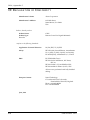
ALESIS CADI REMOTE CONTROL FOR THE M20 PROFESSIONAL 20-BIT DIGITAL RECORDER OWNER’S MANUAL FIRST EDITION VERSION 1.00 APPLIES TO M20 OPERATING SOFTWARE VERSION 1.10 1998 ALESIS CORPORATION CADI, Appendix C CADI MANUAL 1.00 APPENDIX C CADI REMOTE CONTROL The CADI (Controller/Autolocator Desktop Interface) remote control is a centralized control surface designed exclusively for controlling up to eight Alesis M20 digital multitrack tape recorders. The CADI essentially duplicates the front panel of the master M20 (identified as ID1), and adds controls specific to multi-machine applications. Most of the CADI controls operate bi-directionally. Example: if you press a record button on an M20 controlled by the CADI, the corresponding CADI record button will light, and viceversa. However, Alesis recommends performing all commands directly from the CADI unless a machine is offline. Offline machines operate independently of the CADI. In general, CADI buttons initiate the same operations as like-named buttons on the master M20. For example, pressing Stop on the CADI is equivalent to pressing Stop on the master M20. Therefore, this document covers only those aspects unique to the CADI and should be inserted into the binder with the M20 manual. TABLE OF CONTENTS Important Safety Instructions and Compliance Notices ...................................................................2 Safety symbols used in this product ...................................................................................................2 Information to the User for Class A Digital Device (FCC Part 15, Class A)....................................2 CE Declaration of Conformity.............................................................................................................4 Installation.............................................................................................................................................5 Connections...........................................................................................................................................5 AC Power ................................................................................................................................5 Bank Selection and Track Enables.......................................................................................................7 Control of Other ADAT Models .........................................................................................................7 Machine Selection and Status ..............................................................................................................8 Online/Select Buttons (1-8)....................................................................................................8 Machine Edit Select.................................................................................................................8 Editing Parameters of Offline Machines ...............................................................................9 Locked LEDS...........................................................................................................................9 Error Display...........................................................................................................................9 Master Remote Function Buttons...................................................................................................... 10 Roll Back ................................................................................................................................ 10 Replay .................................................................................................................................... 11 Track Enable Groups ............................................................................................................ 11 All Clear................................................................................................................................. 11 Setup ...................................................................................................................................... 12 Eject ........................................................................................................................................ 12 Audio Routing Buttons ...................................................................................................................... 13 Digital Source ........................................................................................................................ 13 Input Select ............................................................................................................................ 14 Input Route............................................................................................................................ 14 Aux Routing .......................................................................................................................... 14 Special Control.................................................................................................................................... 15 Search Master Mode ............................................................................................................. 15 CADI MANUAL 1.00 C-1 CADI, Appendix C IMPORTANT SAFETY INSTRUCTIONS AND COMPLIANCE NOTICES SAFETY SYMBOLS USED IN THIS PRODUCT This symbol alerts the user that there are important operating and maintenance instructions in the literature accompanying this unit. This symbol warns the user of uninsulated voltage within the unit that can cause dangerous electric shocks. All safety warnings in the M20 manual (pages v and vi) apply to the CADI as well, with the addition of the following: 17. Do not use the CADI in an environment where the maximum ambient operating temperature will rise above 26° Celsius (79° Farenheit). INFORMATION TO THE USER FOR CLASS A DIGITAL DEVICE (FCC PART 15, CLASS A) This equipment has been tested and found to comply with the limits for a class A digital device pursuant to Part 15 of the FCC Rules. These limits are designed to provide reasonable protection against harmful interference when the equipment is operated in a commercial environment. This equipment generates, uses and can radiate radio frequency energy and, if not installed and used in accordance with the instructions, may cause interference to radio communications. Operation of this equipment in a residential area is likely to cause interference in which case the user will be required to correct the interference at his own expense. The user is cautioned that changes and modifications made to the equipment without the approval of manufacturer could void the user’s authority to operate this equipment. Use only shielded and grounded cables with this equipment to ensure compliance with FCC Rules. INDUSTRY CANADA (DIGITAL APPARATUS) INTERFERENCE-CAUSING EQUIPMENT STANDARD ICES-003 ISSUE 2 This Class A digital apparatus meets all requirements of the Canadian InterferenceCausing Equipment Regulations. C-2 CADI MANUAL 1.00 Appendix C, CADI CADI MANUAL 1.00 C-3 CADI, Appendix C CE DECLARATION OF CONFORMITY Manufacturer’s Name: Alesis Corporation Manufacturer’s Address: 1633 26th Street Santa Monica, CA 90404 USA declares, that the product: Product Name: Product Type: Recorder CADI Remote Control for Digital Multitrack conforms to the following Standards: Application of Council Directive: 89/336/EEC; 73/23/EEC Safety: IEC 950 (1991) Second Edition, Amendments No. 1 (1992), 2 (1993), 3 (1995), and 4 (1996); EN 60950 (1992), Amendments 1, 2, 3 and 4 EMC: EN 55022:1988 Class A IEC 801-2:1991 2nd Edition, 4kV direct, 8kV air IEC 801-3:1984 2; 3V/m 150MHz-1GHz IEC 801-4:1988 1st Edition 2; 1kV, 0.5kV All tests were performed with fully-shielded cabling. European Contact: Sound Technology 17 Letchworth Point, Lechworth, Hertfordshire, SG6 1ND, England. Phone: +44.1462.480000 Fax: +44.1462.480800 June, 1998 C-4 CADI MANUAL 1.00 Appendix C, CADI INSTALLATION The CADI is intended for use on a desktop, or attached to the optional Alesis BRC Rollaround Stand, available from your dealer. Attach the CADI’s bottom panel to the baseplate of the BRC Stand via the four included screws, NOT to the side panels. The CADI is not rack-mountable. CONNECTIONS The master M20 connects to the CADI via a standard Category 5 cable, terminated at both ends with RJ-45 connectors (these cables are common in Ethernet systems). All other slave ADATs connect to the system via the optical and 9-pin cables, as described in the M20 manual. Do not connect the RJ-45 connectors of the CADI, RMD, or M20 to any other type of equipment or to an Ethernet network. Connect only to Alesis products. If you are also using the Remote Meter Display (RMD), the master M20 patches into the RMD via an RJ-45 cable. The RMD then patches into the CADI with a second RJ-45 cable. With multiple M20s and RMDs, each M20 feeds an RMD. The RMD that connects to the master M20 then patches to the CADI. AC POWER The CADI works with any AC voltage from 90 to 250 volts, 50 to 60 Hz. This eliminates the need for transformers or voltage switches. The CADI ships with an IEC-spec power cord for the country to which the CADI was shipped. The CADI’s IEC-spec AC cord is designed for connection to an outlet that includes three pins, with the third pin connected to ground. Do not substitute a non-grounded AC cord or lift the ground. The ground connection is an important safety feature designed to keep the chasis of electronic devices such as the M20, CADI remote, or RMD at ground potential. Unfortunately, the presence of a third ground pin does not always indicate that an outlet is properly grounded. Use an AC line tester to determine this. If the outlet is not grounded, consult with a licensed electrician. When the AC current is suspected of having unstable voltage and/or frequency, a professional power conditioner should be used. The CADI is supplied with a standard detachable power cord. If the AC cable is too long or short for the installation, you may substitute a UL-approved power cable of the proper length, available in many electronics or computer stores (type “NEMA to CEE”). When powering up, turn on the master (“ID1”) M20 first, then any slave M20s, then any RMDs, and finally, the CADI. CADI MANUAL 1.00 C-5 CADI, Appendix C On power-up: • • • • • • The display will briefly show the software version of the CADI’s internal ROM. Note: this is NOT the software version of the connected M20. The Bank 1-32 button lights. The Online buttons for any connected M20s or ADATs light (offline M20s are placed online when the ID1 machine detects the CADI). The Aux Group Select button lights. The Search mode light always indicates the CADI wheel position, not that of any online machines. Example: If the CADI wheel is set to Shuttle and the master M20 wheel is set to Jog, “SHTL” will light on the CADI and “JOG” will flash on the master. The CADI displays the status of the ID1 (master) machine, as well as the Record/Input Enable status and online status for every machine shown on the CADI front panel. If you turn off the ID1 M20, the display will revert to the “A l e s i s C A D I” start-up message. C-6 CADI MANUAL 1.00 Appendix C, CADI BANK SELECTION AND TRACK ENABLES The CADI has record and input buttons for four M20s, arranged as four groups of 8. There are also four sets of record and input select buttons for the Aux/TC tracks. Two buttons, Aux and TC, enable the Aux or TC tracks for input and record enabling. (Note: If tracks are enabled on a “background” track enable bank or an Aux/TC group, the appropriate bank select button flashes.) All these buttons light when active. Two Bank select buttons determine whether the record and input buttons control M20s 1-4 or 5-8. With Bank 1-32 selected, the four groups of buttons control inputs 1-8, 9-16, 17-24, and 25-32. The four sets of Aux/TC buttons control M20 1 through M20 4. With Bank 33-64 selected, the four groups of buttons control inputs 33-40, 41-48, 49-56, and 57-64. The four sets of Aux/TC buttons control M20 5 through M20 8. Note: If a machine with record- or input-enabled tracks goes offline, the CADI still indicates the track enable status, but this status cannot be changed until the unit goes online again. CONTROL OF OTHER ADAT MODELS In a system with a master M20 whose Sync Out jack is connected to an ADAT, ADAT-XT, ADAT-XT20, LX20 or similar machine, control of basic functions such as transport movements, arming tracks etc. is possible for all ADATs in a system. However, control is limited. For example, the ONLINE button will light for an ADAT-XT20, but pressing the button cannot take the XT20 offline. Other ADAT models will chase to the M20 when it is in jog or shuttle mode, but since their transports are different it is normal for them to stop and start or relocate when jog or shuttle is used. Please keep in mind that mixed systems can not give the fast lock and wind times of an all-M20 system, and that other anomalies are possible, especially with older machines or machines that do not have updated software. CADI MANUAL 1.00 C-7 CADI, Appendix C MACHINE SELECTION AND STATUS ONLINE/SELECT BUTTONS (1-8) Each Online button toggles the online status of the corresponding connected M20. A lit button indicates an online M20. If an online machine becomes disconnected (e.g., communications error, sync cable disconnection, power off, etc.) while this button is on, the corresponding machine’s button turns off and the display shows “Last Slave Unresponsive” before re-establishing the status of the remaining series of slave machines. Notes • • • • • If an M20 is recording, it cannot be toggled offline. If an M20 is in Play, Rewind, FFwd, or Locate mode, putting it offline stops the tape. Pressing an Online button for an unconnected M20 yields a “No Machine Present” prompt until communication is re-established. If the CADI is in a mode or parameter page that uses the Online buttons as Edit Select buttons, a machine cannot be set on or offline. After exiting edit mode, the Online/Select buttons default to indicating the system’s online status (no buttons flashing). To find out how many M20s are connected, Utility page 16 (ID status) displays “nn ADAT(s) connected” (nn = 01-16). MACHINE EDIT SELECT The Online buttons can also select a single machine for editing of the following parameters: • • • Format Tape Offset Track Delay To select a machine for editing: 1. Enter the Mode or Edit page for the parameter to be edited. 2. Press the Online/Select button for the machine whose parameter(s) will be edited. Only one machine can be selected for editing at a time; its corresponding Online/Select button will flash. The Online buttons for any other online machines will be lit solid. If a slave is offline, it cannot be selected for editing. The machine edit select reverts to ID1 if the master machine is turned off and on again. Example: If the ID3 machine was selected for editing and the ID1 machine is turned off, when ID1 is powered back up and you return to one of the appropriate edit pages, ID1 will be selected for editing, not the ID3 machine. C-8 CADI MANUAL 1.00 Appendix C, CADI When operating from a CADI, the master M20 controls the following functions for online slaves: Track Status Group Metering Group SMPTE Chase Pre-roll Post-roll Auto Record Auto Return Auto Play Display Locate 0 Set Locate Roll Back Replay Rehearse Varispeed MIDI Utility Locate Rewind FFwd Stop Play Record Eject Tape Counter Clock Source Sample Rate SMPTE Rate Time Code Source Chase Reference Pitch Mode Locate Select Reference Counter EDITING PARAMETERS OF OFFLINE MACHINES If a unit is offline, machine edit select is not available. Furthermore, if any offline machine parameters are changed, when it goes online again the CADI will not recognize the changes. LOCKED LEDS The 8 dedicated LEDs for eight M20s indicate lock status during Play and Record modes as follows: • • • LED lit = The corresponding M20 is sync-locked LED flashing = The corresponding M20 has lost lock at some point but remains in Play mode. This light remains flashing even if the unit regains lock to make sure you know lock was lost. LED off = The corresponding M20 is stopped or in a fast wind mode (including Locate). The LOCKED indicator in the CADI’s display lights when all online M20s that are in Play or Record mode have locked. ERROR DISPLAY The ERROR indicator in the CADI’s display lights when any online M20 has an interpolation error. The error counter (in UTILITY menu #21) shows the error rate of the top (ID1) machine only. CADI MANUAL 1.00 C-9 CADI, Appendix C MASTER REMOTE FUNCTION BUTTONS ROLL BACK This locates back a user-defined amount, starting from the ABS tape time at the moment the Roll Back button was pressed (even during a locate). Example: defining a 10 second roll back moves the tape from 10:00 to 09:50 upon pressing Roll Back. During a roll back, the Roll Back button lights and the Rewind button flashes. The following table shows how to edit the roll back time. Action Initiate Roll Back time edit You press… Press and hold Edit, then press Roll Back Adjust Roll Back time The Numeric Keypad or Up/Down buttons edit the field. The default is 10 sec. Exit Roll Back time edit Another edit parameter button (e.g., SMPTE Chase), or the Edit button again You see… The Edit button lights. Any other edit group button light turns off. The display shows the Roll Back Time as “nnsec”, where nn is 00 - 59 seconds. The Edit button turns off if Edit is pressed. The display returns to the previously selected page. Notes • • • • • C-10 Play can be deferred during a roll back, which will follow the same “Locate Before Play: On/Off” rules as a normal locate. Multiple Roll Back button presses do not accumulate (e.g., pressing Roll Back once for a 25 second roll back, then pressing Roll Back again before the M20 has located, does not produce a 50 second roll back). While in the Edit Roll Back page, the Roll Back button will remain active for executing a roll back. The roll back time is retained in memory even if the ID1 machine is turned off then on again. A roll back cannot be executed when an online machine is in Record mode. CADI MANUAL 1.00 Appendix C, CADI REPLAY This locates back to the last location where play mode was initiated. This location cannot be edited, and corresponds to the moment a button was pressed to initiate play. After initiating Replay, the Replay button lights and the Rewind or FFwd button flashes. Notes • • • • • • Pressing Play updates the Replay location register, even when machines are playing, except when pressing Play to punch out of Record mode. In record mode, using the Play button to punch outdoes not update the Replay location register. When in One-button Record mode, and not in Play mode already, pressing Record to punch in updates the Replay location register. Play can be deferred during a Replay operation, so Replay will follow the same “Locate Before Play: On/Off” rules as a normal locate. Pressing Replay during a locate operation ends the locate and initiates Replay mode. The Replay address is volatile, so turning the ID1 machine off then on again returns the Replay address to its default value (00:00:00:00.00, ABS time). TRACK ENABLE GROUPS You may store and recall four different Groups of Track Enable settings as follows: Action Select track enables that will make up a Group You press… Desired Input and Record enable buttons Store a Group …and hold the Set Group button, then press one of the Track Enable Group buttons (1 - 4) Recall a Group The desired Track Enable Group button (1-4) You see… Corresponding Input and Record enable buttons are lit or flashing The display shows “Track Group n Stored,” where n is the Track Enable Group button you selected Input and Record enable buttons associated with the Group are lit or flashing Group settings are volatile, so turning the ID1 machine off then on again clears all Group settings. ALL CLEAR This button clears all record and input enabled tracks, including TC & Aux Enables, unless All Input is enabled. In this case, All Clear disables only Record-enabled tracks (leaving those tracks in Input mode). As the TC Track is not subject to All Input enable, pressing All Clear disables a record/input-enabled TC track. CADI MANUAL 1.00 C-11 CADI, Appendix C SETUP This unique CADI function allows you to switch several timecode-related variable settings simultaneously. It can recall any of 10 stored (namable) setups at any time (except when recording or chasing SMPTE) for each of the following master (ID1) M20 functions: • • • • • • • SMPTE Chase Internal Generator Clock Source Sample Rate SMPTE Rate TC Source Chase Reference The on/off settings of SMPTE Chase and Internal Generator are not saved as part of a setup, only their underlying variables. Pressing the Setup button causes it to light, and the display indicates “Setup nn,” where nn = 01 through 10. The cursor remains under the setup number; to move to the name field, press Enter/Name. Edit the name (up to eight characters) with the keypad and cursor buttons. Changing any of the setup parameters automatically edits and updates the Setup. Setups are part of the M20 MIDI sysex dump, and may be saved and loaded to MIDI. However, Setups are NOT part of the “Save/Load data to tape” function. Only the current recalled setup will be saved to tape. Tip: Use Setup to easily switch the M20 between commonly-used modes. For example, you could design a setup named “Freerun” with INT GEN set to your preferred time code defaults when generating time code onto other machines. Another setup named “Slave 29” would set the M20 to chase-lock to external time code coming in at the NTSC video rate. To exit the Setup page, press any of the other parameter buttons (e.g. Locate Select, Display, Varispeed, etc.). EJECT As with professional VCRs, the Eject button lights only when all online M20s have no tapes inserted. Only those M20s that are online will eject tapes upon pressing the CADI’s Eject button. If any machine is in Record mode, the Eject button will be ignored by all connected online units. C-12 CADI MANUAL 1.00 Appendix C, CADI AUDIO ROUTING BUTTONS Input Select, Input Route, and Aux Route configurations use the Input Enables for setup. Pressing any audio routing function button causes the Input Enable buttons of online M20s to indicate and perform the route editing. DIGITAL SOURCE Pressing the Digital Source button once causes it to light, and the display indicates “Dig Source = aaaaaaaa”, where aaaaaaaa = OptLoop or Local. With Local selected, pressing the Digital Source button a second time opens a second page that says “Dig Source n = bbbbbbbb.” • The n field selects the machine to be edited; n = 1 - 8 (indicating online machines only). • The bbbbbbbb field chooses the machine’s digital source: Optical, Trk Copy, or I/O Card (assuming it detects an I/O card). In Local mode, pressing the Digital Source button multiple times toggles between the Digital Source Mode and Digital Source selection pages. When the digital source mode is OptLoop (optical loop), the digital source selection page is not available. OptLoop mode defaults to setting the digital out mode for all online slave M20s to “Dig Thru” (see Utility Page 1 of the M20 manual). This allows for convenient digital audio routing between M20s when selecting digital source tracks in the Input Routing setup (Track Copy and I/O Card are not available in OptLoop mode). When a track is selected as a digital source track under Input Routing, the associated M20 will automatically change its digital output setting (Utility Page 1) to 20-bit. All other M20s will configure to Dig Thru mode. Only one M20 can be a digital source machine. When the Digital Source Mode is changed to Local, returning to OptLoop mode resets the digital source track machine to ID1. When in OptLoop mode, using Input Select is not allowed since all inputs must remain digital while in OptLoop. In Local mode, each M20’s Digital Source selection can be set independently, but the source clock(s) must still be synchronous with the master M20 since it controls the slaves’ sample clocks. Optical, Track Copy, and I/O Card (if present) modes are available. If an M20 is offline, that machine’s Digital Source page will indicate that the corresponding M20 is offline. Example: With ID3 offline and four other connected M20s online, the display will indicate “Dig Source 3 = offline” when ID3 is selected. Entering a high-level parameter page (e.g., pressing the Locate Select button) exits the Digital Source page. CADI MANUAL 1.00 C-13 CADI, Appendix C INPUT SELECT This button flashes for 10 seconds when the mode is active; the display says “Use track input switches.” If you don’t press any track input buttons during this time (or if there is any 10-second period during input selection when no switches are pressed), the function times out, then reverts to the previously-exited page. The CADI’s track input buttons will light to indicate digital input, and turn off to indicate analog input (as confirmed by the display on corresponding M20s). When the selected input is digital and no clock reference is detected, the associated Input button flashes until the M20 receives a valid clock. INPUT ROUTE This button flashes for 10 seconds when the mode is active. If you don’t press any Input Enable buttons during this time (or if there is any 10-second period during input route selection when no buttons are pressed), the function times out, then reverts to the previously-exited page. If all inputs are set to analog, press Input Route once to select analog routing; use the Input Enable switches to choose the type of routing, as with the M20. When in analog input routing mode, the display indicates “Select analog input tracks.” The input enable buttons light for selected tracks. If all inputs are set to digital, press Input Route once to select digital routing, and use the Input Enables to select individual tracks. When in digital routing mode, the display indicates “Select dig (Optical, Trk Copy, or I/O Card) Src Tracks.” The Input Enable buttons light for selected source tracks. If the inputs are mixed between analog and digital, the digital routing page will appear first. Press the Input Route button a second time to select analog routing. The Input Enable buttons will update to reflect the selected routing mode. AUX ROUTING This button flashes for 10 seconds when the mode is active, then reverts to the previouslyexited page. If you don’t press any track input buttons during this time (or if there is any 10-second period during input route selection when no buttons are pressed), the function times out, then reverts to the previously-exited page. The display indicates “Select individual tracks or select AUX track for automated routing.” Use the track input buttons to select the channels that will be recorded to the associated machine’s AUX track when its AUX track is recording. A track input button lights when that channel is selected as an input to the associated machine’s AUX channel. For automated AUX routing, press the desired machine’s AUX track input button. The AUX track input button lights when enabling automated AUX routing for that machine, and the machine’s corresponding Input Enables will turn off. Selecting All Safe while in Manual Aux Routing mode disables aux routing; selecting All Input sets all connected online channels for aux routing. All Safe and All Input have no corresponding function when Auto Aux Routing is selected. C-14 CADI MANUAL 1.00 Appendix C, CADI SPECIAL CONTROL SEARCH MASTER MODE This function accommodates situations where you want to use jog on a machine that is not the master (e.g., to find a particular point on the tape of that machine only). In this case, you don’t want the non-master machine to follow the master, but instead, to act as a “temporary locate master” so all machines (including the ID1 master) park where the designated search master machine parks after a jog or shuttle operation. To set which online machine controls the parking address for all machines: 1. Press and hold Search for 2 seconds to enter Search Master Edit mode (releasing the Search button before 2 seconds toggles in/out of Search mode). The display shows “Search Master: n” (n = 1 — 8 or None). 2. While holding Search, use the numeric keypad buttons (1-8, 0) or Up/Down buttons to select a search master. Releasing the Search button exits the edit mode without changing the Search mode status. Selecting a machine other than ID1 as a search master and activating Search mode (Jogging or Shuttling) causes the display to indicate momentarily “Machine n Search Master” (n = 1 8) or “No Search Master” when None is selected. If you pause a search, ID1 will query the search master, update ID1’s tape counter, and locate all connected machines to the position of the designated search master. When search master equals None, ID1 will not send a locate command to the slaves. All decks will remain parked after a search. Upon exiting Search mode, Pressing Play will follow the Locate-Before-Play rule (assuming Locate Before Play is on). The default search master is machine 1, and the selection is not retained through an ID 1 power-cycle. Releasing the Search button exits Search Master Edit mode, and the CADI reverts to displaying the previously exited page (with the exceptions of the Aux Routing Group). If a routing group mode is active, holding the Search button for 2 seconds will auto-exit any of the routing modes (excluding Digital Source) and enter Search Master Edit mode. Note that ID1 must remain online, and the user must observe the time code display when actively jogging or shuttling because when a slave is the search master, the master’s tape motion will offer a rough indication of the search master machine’s position until Search mode is paused. CADI MANUAL 1.00 C-15