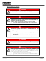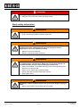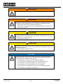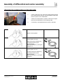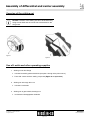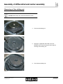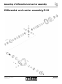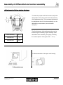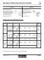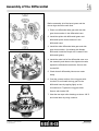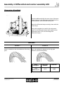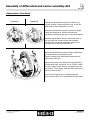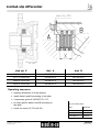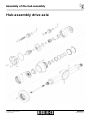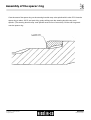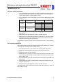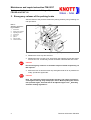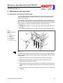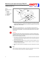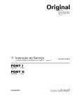
1
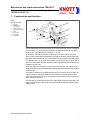
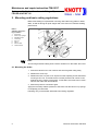
Axl e Service Manual © Kessler & Co. GmbH & Co.KG All rights reserved Copyright © Firma Kessler & Co. GmbH &Co.KG Reproduction and dissemination of this documentation in any form (photocopying, printing or electronic dissemination) is prohibited without the written permission of Kessler & Co. GmbH & Co.KG. This documentation is not subject to revision. We reserve the right to make modifications without prior notice. © Kessler & Co. GmbH & Co.KG All rights reserved 08.06.2011 Service Manual © Kessler & Co. GmbH & Co.KG All rights reserved Introduction Axles, transmissions, wheel gears and non drive wheels from Kessler & Co. GmbH & Co.KG (hereinafter referred to as KESSLER) are designed and manufactured in accordance with the state of the art and the recognised technical safety regulations. This documentation describes the state of the art at the time the documentation was created. Although the documentation was created with great care KESSLER accepts no liability for any errors with respect to the depiction and description. This documentation is not subject to revision service. We reserve the right to make modifications without prior notice. Due to continuous developments and technical improvements of our products, the depictions in the following work steps may deviate or differ from the actual product / component. Drawings, graphics, pictures and photos are generally not true-to-scale. This manual was developed for technicians who have been trained by KESSLER for the repair and servicing of KESSLER axles, transmissions, wheel gears and non drive wheels. The manual must be stored where it is available to the technicians at all times. The company will not be liable for damages and consequential costs resulting from improperly executed work by third parties. This also applies if spare parts other than those specified by KESSLER are used. KESSLER offers customer service tools that make working on axles, transmissions, wheel gears and non drive wheels easier and safer. © Kessler & Co. GmbH & Co.KG All rights reserved Introduction Service Manual 23/09/2013 General information Axles, transmissions, wheel gears and non drive wheels from KESSLER may be used only in technically flawless condition and as specified, in a safety- and hazard-conscious manner and in compliance with the manual. Defects, especially those that could impair safety, must be remedied immediately. It is likewise prohibited to use defective or improperly serviced, repaired or modified axles, transmissions and non drive wheels. In addition to and having priority over the warning and safety information in this manual, the applicable national safety and environmental regulations also apply. Maintenance, repairs or modifications may be performed only by trained specialists. The manual must be read prior to starting maintenance, repairs or modifications. In case of ambiguities and uncertainty, always consult KESSLER. When performing maintenance and repairs, comply with the safety regulations and the statutory requirements for preventing injuries and damage to the product. Persons who perform these tasks are obligated to become familiar with and comply with these regulations. These persons are responsible for the occupational safety. After conducting maintenance and repairs, the product must be inspected to ensure that it is functioning properly. In case of major repairs and overhauls it is recommended to send the entire components (axle, gear, wheel gear and non drive wheel) to KESSLER. All maintenance instructions in the KESSLER manual must be complied with. Assembly and disassembly must be carried out in a clean work area. Use special tools from KESSLER for the work. Before reinstalling used parts, they must be inspected for damage, undamaged contact surfaces and wear. It is especially important to ensure that no chips or other foreign objects remain in the axles, transmissions, wheel gears and non drive wheels. To remove the components (axle, gear, wheel gear and non drive wheel) from the vehicle, read the instructions of the vehicle manufacturer. The following descriptions assume that the component has been removed and mounted on a mounting device for further processing. © Kessler & Co. GmbH & Co.KG All rights reserved General information Service Manual 23/09/2013 Safety Explanation of the warning information and symbols appearing in the Service Manual DANGER Highest danger level There is immediate danger of death or severe injury in case of failure to comply with this safety notice. this arrow indicates the absolutely necessary measures for preventing the specific danger WARNING Second highest danger level There is possible danger of death or severe injury in case of failure to comply with this safety notice. this arrow indicates the absolutely necessary measures for preventing the specific danger CAUTION Third highest danger level There is danger of minor injury or property damage in case of failure to comply with this safety notice. this arrow indicates the absolutely necessary measures for preventing the specific danger NOTICE Failure to observe this will result in dangers to the machine and its functions. Information Offers additional information to facilitate working. © Kessler & Co. GmbH & Co.KG All rights reserved Safety information page 1 of 4 Service Manual 18/11/2013 Special types of danger DANGER When working on brakes, make sure that releasing the braking force cannot result in unintentional movement of the machine. DANGER When working on assemblies with spring actuator elements, such as: brakes and brake cylinders, whether service brake or parking brake. The assemblies are under spring tension. Improper opening can cause parts to suddenly be released and fly off. In such cases, always comply with the safety, repair and maintenance instructions of the suppliers. DANGER Special care is necessary when working on wet multiple disk brakes. They are under high spring tension. Improper installation and/or removal of the brake can cause parts to suddenly be released and fly off. Do not pre-tension and release the tension on the springs by means of the brake housing screw connections! Open the screw connection of this brake only using a suitable press or mounting device Preferably, installation/removal should be carried out by KESSLER DANGER Never remain directly in front of the wheel rim during deflation or inflation. The pressure inside the tyre could cause parts to suddenly be released and fly off. DANGER When removing and mounting wheels on vehicles with clamped rims there is a danger that the tyre pressure can cause damaged parts of the rim to become released explosively when removing the clamped rim, which can cause severe or fatal injuries to the mechanic. Completely deflate the tyre before performing any task Never remain directly in front of the wheel rim during deflation or inflation of tyres © Kessler & Co. GmbH & Co.KG All rights reserved Safety information page 2 of 4 Service Manual 18/11/2013 DANGER Comply with tightening torque for wheel nuts. Retighten wheel nuts after a short operating period! Basic safety information WARNING Comply with the safety signs on the axle. They must be kept in legible condition at all times. WARNING Only tools and equipment of the highest quality may be used; tools and equipment must be undamaged and electrical equipment must be approved for use in the respective country. Never use improvised devices. Use only original tools from KESSLER. WARNING Due to the unforeseeable dead weight of the single parts (e.g. wheel hub) or complete axles, transmissions, wheel gears or non drive wheels it is possible that they can fall or tip over during assembly work. Always use suitable, undamaged and tested cranes and load attachment gear for the respective load. Never work or stand under suspended loads Secure parts with a lashing strap and/or support Wear safety shoes WARNING Movement / rotation of different parts can result in the danger of injury to limbs. Never reach between moving parts with your hands © Kessler & Co. GmbH & Co.KG All rights reserved Safety information page 3 of 4 Service Manual 18/11/2013 WARNING Welding repairs are permitted only in coordination with KESSLER! WARNING Work on an axle, a transmission, a wheel gear and a non drive wheel is allowed only if the temperature of the respective component permits. Make sure that the oil has cooled before draining it Make sure that rotating parts have cooled before starting to remove them Wear fireproof gloves CAUTION During all machining work on metal parts, during which there is a danger of splinters (abrasive cutting, deburring, cleaning with compressed air, etc.), flying metal parts can cause eye injuries. Wear protective goggles CAUTION It is prohibited to wear loose clothing and long open hair when working on axles, transmissions, wheel gears and non drive wheels! Oils and greases can cause allergic skin reactions. Wear suitable protective clothing NOTICE Always observe the technical data (brake connections, tightening torques of screws and wheel locking nuts, etc.). Compliance with these specifications is very important for the safety of other people. For information on connections: see installation drawing For information on tightening torques: see “Important Information” For information on the drive assembly: see “Drive assembly” For information on the hub assembly: see “Hub assembly” For information on the planetary gear drive: see “Planetary gear drive” For information on the brakes: see “Brakes” © Kessler & Co. GmbH & Co.KG All rights reserved Safety information page 4 of 4 Service Manual 18/11/2013 Table of contents 1 Important remarks 2 Lubrication intervals and maintenance instructions 3 General instructions for correct assembly and disassembly Service tools 4 Assembly drive assembly 5 Assembly hub assembly 6 Assembly panetary gear drive 7 Assembly service brake 8 Assembly parking brake © Kessler & Co. GmbH & Co.KG All rights reserved Service Revised 01.09.2007 © Kessler & Co. GmbH & Co.KG All rights reserved Section Important remarks 1 Service Revised 27/02/2013 Section Important remarks 1 1.1 Important remarks Checking of screw connections, safety devices and corrosion For safety reasons, the vehicle operator must check and service all important screw connections and safety devices at regular intervals. • Wheel nuts • Nuts of axle mounting bolts • Tightening screws on housing joints and steering components will break the Loctite bond, which means the screws have to be reinstalled! Secure screw connections and joints in accordance with specifications; in case of doubt, contact Kessler & Co. GmbH & Co.KG. • Corrosion and cracks on support components (e.g. the axle spindle) are not permissible for reasons of operational safety and leaks. Supporting components with cracks must be replaced! • Cracks on steering components are not permissible for reasons of operational safety. Steering components with cracks must be replaced! Check of brakes • Inspect brake lining and brake drum / brake disc regulary as well as wear of brake system parts. • Inspect the free movement of brake system rods. • In case of signs of excessive heating, consult a brake specialist or the manufacturer. Service © Kessler & Co. GmbH & Co.KG All rights reserved Revised 19/02/2013 Page 1 of 2 Section Important remarks 1 1.1 Service instructions • Assembly and disassembly may be carried out only by trained specialists. • Repair welding is permissible only after consulting Kessler & Co. GmbH & Co.KG! • To remove the axle from the vehicle, read the instructions in the vehicle manufacture’s manuals. The following descriptions assume that the axle has been removed and mounted on a jig for further processing. • Always comply with the safety regulations for your country. There is no guarantee that they correspond to the instructions in this manual. Service © Kessler & Co. GmbH & Co.KG All rights reserved Revised 19/02/2013 Page 2 of 2 Section Important remarks 1 1.2 Control light • A control light in the drivers cabin must inform about the operation of inter axle and cross diff. lock separately. Further the control light should show with already the first lock operated, even if the other locks are not yet connected or already disconnected (electrical installation parallel). Service © Kessler & Co. GmbH & Co.KG All rights reserved Revised 29/09/2012 Page 2 of 2 Section Important remarks 1 1.3 Necessary to contact Kessler & Co. GmbH & Co.KG. In case of questions, contact Kessler & Co. GmbH & Co.KG. In case of major repairs or overhaul, it is advisable to send the entire axle to Kessler & Co. GmbH & Co.KG. Service © Kessler & Co. GmbH & Co.KG All rights reserved Revised 29/09/2012 Page 2 of 2 © Kessler & Co. GmbH & Co.KG All rights reserved Section Lubrication intervals and maintenance instructions Service Revised 01/10/2012 Section Lubrication intervals and maintenance instructions 2.1 General lubrication instructions Fill levels Are checked at the level control plugs. Oil change 1. Place the vehicle in a horizontal position. 2. Draining of the oil is to be accomplished only in warm condition. Clean all lubrication points before, opening them. Open the drain holes on the carrier assembly, on the wheel assemblies, and if present, on the interaxle differential and drop gear housing. On the hub assemblies, the drain plug should be turned downward. 3. Oil draining 4. Replacement of the oil draining plugs 5. Remove the oil filler plug as well as the oil level control plug on the carrier assembly, on the wheel assembly, and, if present, on the interaxle differential and drop gear housing. (See page 3 lubrication points). 6. Oil filling 7. Check the oil level at the oil level plug hole (Overflow control). Wait a few minutes. If the oil level falls, add oil until the level remains constant. 8. Clean the grease nipples before lubrication. Preservation of Kessler axles for an extended storage period Replace the breather with a screw plug with a sealant in order to avoid water intrusion and oil leakage. Fill axles completely up with oil, the same applies to wet disc brakes. Protect machined surfaces (for example: rim surface, steering cylinder, brake disc, ….) with additional anticorrosive. Before putting the axle into operation Drain storage oil. Fill the axle with suitable oil (see service manual Kessler & Co. GmbH & Co.KG) to the required oil level. Check sealing contact surfaces for corrosion. Check the seals immediately after start-up for leakage and renew them if leaking. Completely remove the anticorrosive machined surfaces (for example: rim surface, steering cylinder, brake disc, ….). The rim face must be cleaned from rust or grease in order to secure a correct friction tight with the rim and to prevent loosening of the rim. Check axle structure for corrosion, especially after several years of storage. Service © Kessler & Co. GmbH & Co.KG All rights reserved Revised 29/09/2012 Page 1 of 1 Section Lubrication intervals and maintenance instructions 2 2.2.1 Lubrication points The binding lubrication points have to be taken from the according installation drawing of the axle Single drive assembly *The position is dependent from the respective axle version. Drive assembly with throughdrive *Version with interaxle differential. Fill 1,5 liter oil at *I for first - time filling and for refilling! Drop gear D51 / D108 *II – only at version with separately oil space. Cardan shaft intermediate bearing I = Oil fill plug II = Oil level control plug III = Oil drain plug IV = Grease nipple Service © Kessler & Co. GmbH & Co.KG All rights reserved Revised 29/09/2012 Page 1 of 1 Section Lubrication intervals and maintenance instructions 2 2.2.2 Lubrication points The binding lubrication points have to be taken from the according installation drawing of the axle Hub assembly with planetary gear drive Lubrication points at universal joint and brake shaft. (If not maintenance – free) Hub assembly with wet disc brake Tumbler bearing I = Oil fill plug II = Oil level control plug III = Oil drain plug IV = Grease nipple Service © Kessler & Co. GmbH & Co.KG All rights reserved Revised 29/09/2012 Page 1 of 1 Section Lubrication intervals and maintenance instructions 2 2.3 Lubricants and lubrication intervals Lubrication point Drive assembly Wheel hub planetary gear drive Interaxle differential Drop gear/ Gear boxes Wheel bearing oil lubricated Multi disk parking brake Lubricant Hypoid – gear oil per MIL-L – 2105 B / API GL 5 Hypoid – gear oil in multi – range characteristic per MIL-L – 2105 C / D / API GL 5 SAE 90 or multi grade oils for normal external temperature SAE 75 W – 90; SAE 75 W – 85 for external temperature lower – 10°C Remarks Lubrication intervals 1.) Oilchange Check oil level at control points monthly SAE 140 or multi grade oils for external temperature over + 30°C Hydraulicoil ISO VG 32 Oilchange wet running Cardan shaft intermediate bearing Steering knuckle bearing Fuchs Renolit LX-NHU 2 if provided for Steering knuckle bearing Multi – use grease lithium saponified groove penetration per NLGI 2 Universal joint Track rod Steering cylinder -ball head/ -spherical plain bearing every every at least 500Bh 1000Bh 1x per 1x in 1000Km 5000Km 10000Km year 2 years ⊕ ⊕ ⊕ ⊕ ⊕ ⊕ ⊕ ⊕ ⊕ ⊕ ⊕ ⊕ ⊕ ⊕ ⊕ ⊕ ⊕ ⊕ ⊕ ⊕ ⊕ ⊕ ⊕ ⊕ ⊕ f. e. Fuchs Renolit MP 150 pinion bearing if provided for ⊕ ⊕ if provided for ⊕ ⊕ if provided for ⊕ ⊕ if grease lubricated ⊕ Attention! 2.) Brake shoe bearing Attention! 2.) if grease lubricated Wheel bearing see chapter -7- external cooled oilchange not external cooled oilchange ⊕ at least ⊕ maintenance reduced Brake shaft bearing Wet disc brake after 100Bh ⊕ Lightly greased at brake shoe new assembly Change grease at wheel hub disassembly ⊕ dependent on tank volume / cooling system / operation conditions ⊕ ⊕ ⊕ (Bh = Hours of operation) Service © Kessler & Co. GmbH & Co.KG All rights reserved Revised 29/09/2012 Page 1 of 2 Section Lubrication intervals and maintenance instructions 2 2.3 1.) Whichever occurs first. 2.) The bearing point is to be lightly lubricated only, to avoid the penetration of grease in the interior of the brake (use only hand operated grease gun and remove surplus grease!). Check regularly the brake shafts and if need correct the lubrication intervals (danger of overheating!) Important – if a noise is produced on axles with self locking differentials On the axles with self locking differentials, a noise is produced if normal oils are used. In case of abnormal noises and in case of a jerky roll off of the tyres, use gear oil EP with additives of the “Limited Slip” type conforming to specification M 2C - 104 A. Service © Kessler & Co. GmbH & Co.KG All rights reserved Revised 29/09/2012 Page 2 of 2 Section Lubrication intervals and maintenance instructions 2 2.3.1 Recommendable hypoid gear oils corresponding MIL-L 2105 B/API GL 5 resp. MIL-L 2105 C/D/API GL 5 ARAL - Gearoil Hyp 90 AVIA - Gearoil Hypoid 90 EP BP - Multiuse - Gearoil EP SAE 90 ELF - Tranself Typ B 90 / Tranself Typ B 80 W - 90 ESSO - Gearoil GX - D 90 FINA - Pontonic MP SAE 85 W - 90 FUCHS - Renogear Hypoid 90 MOBIL - HD 90 - A SHELL - Spirax MB 90 / HD 90 TEXACO - Multigear EP SAE 85 W / 90 AGIP - Rotra MP / Rotra MP DB On no account use “normal” gear oils! Service © Kessler & Co. GmbH & Co.KG All rights reserved Revised 01/10/2012 Page 1 of 1 Section Lubrication intervals and maintenance instructions 2 2.4 General maintenance instructions Check - and maintenance points Remarks Maintenance intervals 1.) after after every every at least 50Bh 100Bh 500Bh 1000Bh 1x per 500Km 1000Km 5000Km 10000Km year Wheel bearing Inspect, if necessary readjust wheel bearing Wheel nuts Check and tighten with a torque wrench (after tire change after 50km and 200km) ⊕ ⊕ ⊕ Castle nuts/track rod Screws/drive flange Nuts/axle mounting bolts Check and retighten (Verify the adjustment) ⊕ ⊕ ⊕ Brakes (see also chapter 7) Check lining wear, if necessary readjust, control the proper operation of the brake shafts ⊕ Wet disc brake Check lining wear Wet disc brake spring load design Check lining wear Steering - and trackrod lever Check and retighten mounting bolts ∗) Bolted connections Check from time to time (for example drive assembly) ⊕ ⊕ ⊕ monthly ⊕ ⊕ ⊕ ⊕ ⊕ Ring gear support bolt on drive assembly Readjust (if necessary) Seals Check from time to time monthly Differential lock Check function and the automatic return in original position monthly ⊕ (Bh = Hours of operation) *) If the bolts are moving (Loctite brakes loose), the lever has to be mounted once more. 1.) Whichever occurs first. Service © Kessler & Co. GmbH & Co.KG All rights reserved Revised 01/10/2012 Page 1 of 1 © Kessler & Co. GmbH & Co.KG All rights reserved Section General assembly /disassembly instructions service tools Service Revised 01/10/2012 Section General instructions for correct assembly and disassembly 3.1 General instructions for correct assembly and disassembly General instructions for disassembly The disassembly occurs made inverted to the respective assembly instruction. Drain oil before removing, check for presence of metal particles. Mark the parts to each other before dismantle. Never use a hard object to separate tightly fitted assemblies. To remove bearings, drive flange and similar parts, use adequate pull-off tools. It is recommended that the special tools according 3.6 be used for disassembly. Before disassembly, the destruction of bearings and other components must check, if it is necessary to destroy it. Systematically replace used seals, O-rings and if needed bearings on disassembly. Replace or clean corroded parts. Do not place parts on dirty surface. General instructions for assembly Clean parts before reassembly. The cages of bearings rotating in oil must coat with oil at reassembly. During mounting of radial seal rings, pay attention that there is sufficient overlap to the housing bores. Pay attention for a plain alignment of the radial seal ring. The seal lips may never be encountered Loctite! Oil seal rings and particularly the anti–dust lip seals must fill with grease. The universal joint shafts and the axle shafts must forcibly mounted (they must slide). Seal ring treads on flanges, shafts and so on, must preserve with Castrol Rustilo DWX 32 before mounting. Refill oil after assembly! © Kessler & Co. GmbH & Co.KG All rights reserved Service Revised 01/10/2012 Section General instructions for correct assembly and disassembly 3 3.2.1 Application of Loctite and operating supplies Application of Loctite and operating supplies 1. LOCTITE 2. EPPLE Type colour Application 243 blue Lightly locked screws 262 red Middle locked screws 270 green Highly locked screws 270 green Increased coefficient of friction in contact surfaces 510 orange Surface gasket 572 white Special gasket 638 light-green Gluing with big width of slit 5926 and blue 209 125 Surface gasket 33 grey Surface gasket grey Elastic gasket 3. DIRKO Remarks for working up Loctite and operating supplies Threads and surfaces have to be cleaned and free from colour, oil and grease before applying Loctite. Loctite will harden under following conditions: Exclusion of air Metal contact Increased temperature Pre - assembly and control tightening must do in a short time (5 to 10 min.) The time between gluing and mounting of the parts should be shorter than 1h. Exception: parts made from nonferrous metal have to be glued within one minute. Assembled parts must remain unloaded for at least 24 hours. Loctite quantity: At screws: At contact surfaces: 1 bead Pay attention for a sufficient Loctite application! Service © Kessler & Co. GmbH & Co.KG All rights reserved Revised 01.06.2010 Page 1 of 1 Section General instructions for correct assembly and disassembly 3 3.2.2 Application of Loctite and operating supplies of hub assembly Safety blocked parts Joint Spacer ring Contact surface 572 - Axle spindle Screws 262 - Axle spindle Contact surface 270 - Grommet in planetary housing 270 - Disc in axle spindle 270 - Adjusting screw with nut in planetary housing 270 - Support Screw 262 - Ring gear retainer Screws 270 - Pol wheel Contact surface 638 - Steering lever Track rod lever Screws 262 - Steering lever Track rod lever Contact surface 270 - Wheel hub cover Thread 572 - Contact surface 572 - Contact surface 270 - Radial seal rings Rubber casing Radial seal rings Steel casing Loctite Operating supplies Wheel safety nut → see chapter 5 → Adjustment of wheel bearings Service © Kessler & Co. GmbH & Co.KG all rights reserved Revised 01/10/2012 Page 1 of 1 Section General instructions for correct assembly and disassembly 3 3.2.3 Application of Loctite and operating supplies of differential and carrier assembly Safety blocked parts Joint Loctite Operating supplies Drive flange Nut surface - Epple 33 alternative Dirko grey Diff-housing Screws 262 - Contact surface 572 - Contact surface 510 - Drop gear housing Contact surface 510 - Diff.carrier Contact surface - Epple 33 alternative Loctite 5926 and 209125 Through drive cover Contact surface 510 - Differential strap Screws 262 - Adjustment nut screw Screw 270 - Ring gear Screws 262 - Ring gear Contact surface 270 - Ring gear support Cap 270 - Ring gear support Thread - Epple 33 alternative Dirko grey Shifter cylinder (Diff-lock) Diff.carrier (Through drive) Service © Kessler & Co. GmbH & Co.KG all rights reserved Revised 01/10/2012 Page 1 of 1 Kapitel General instructions for correct assembly and disassembly 3 3.3 Tightening torques General instructions for tightening torques (Nm) µ = 0,14 All tightening torques are rated in Nm. Tolerance of the tightening torques is ±5% (assuming a manually operated torque spanner is used) Tightening torque of metric coarse-pitch thread Thread M4 M5 M6 M8 M 10 M 12 M 14 M 16 M 18 M 20 M 22 M 24 M 27 M 30 Screw Nut Screw Nut Screw Nut 8.8 8 10.9 10 12.9 12 3,0 5,9 10 25 49 85 135 210 300 425 580 730 1100 1450 4,4 8,7 15 36 72 125 200 310 430 610 830 1050 1550 2100 5,1 10 18 43 84 145 235 365 500 710 970 1220 1800 2450 Service © Kessler & Co. GmbH & Co.KG All rights reserved Revised 01/10/2012 Page 1 of 2 Kapitel General instructions for correct assembly and disassembly 3 3.3 Tightening torque of metric fine pitch thread Thread M8x1 M 10 x 1 M 10 x 1,25 M 12 x 1,25 M 12 x 1,5 M 14 x 1,5 M 16 x 1,5 M 18 x 1,5 M 20 x 1,5 M 22 x 1,5 Screw Nut Screw Nut Screw Nut 8.8 8 10.9 10 12.9 12 27 55 52 93 89 145 225 340 475 650 39 81 76 135 130 215 330 485 680 920 46 95 90 160 155 255 390 570 790 1050 Thigtening torque for galvanized bolts and nuts! Regard reduced thightening torque for galvanized bolts and nuts! Tightening torque for brake caliper dowel screws (greased !) M 20 x 1,5 M 27 x 2 400 + 100 900 + 100 Tightening torque of the nut for steering stop 300 Approximate value for the thigthening torque for screw plug Thread M14x1,5 Tightening torque Tightening torque (Approximate value) ca. 45 (Screw plugs with O-Ring) 45 M16x1,5 ca. 60 - M22x1,5 ca. 100 100 M24x1,5 ca. 120 - M30x1,5 ca. 160 - M42x1,5 ca. 260 - M45x1,5 ca. 280 - Service © Kessler & Co. GmbH & Co.KG All rights reserved Revised 01/10/2012 Page 2 of 2 Kapitel General instructions for correct assembly and disassembly 3 3.3.1 Units Comparison table for units 25,40 mm = 1 in (inch) 1 mm = 0,0394 in (inch) 1 kg (kilogram) = 2,205 lb (pounds) 9.81.Nm (1 kpm) = 7,233 lbf x ft (pound force foot) 1,356 Nm (0,138 kpm) = 1 lbf x ft (pound force foot) 1 bar (1,02kp/cm2) = 14,5 psi (pound force per square inch lbf/in2) 0,070 bar (0,071 kp/cm2) = 1 psi (lbf/in2) 1 Litre = 0,264 Gallon (Imp.) 4,456 Litre = 1 Gallon (Imp.) 1 Litre = 0,220 Gallon (US) 3,785 Litre = 1 Gallon (US) 1609,344 m = 1Mile (land mile) 0°C (Celsius) = +32°F (Fahrenheit) 1°C (Celsius) = +33,8°F (Fahrenheit) 0°C (Celsius) = 273,15 Kelvin 1°C (Celsius) = 274,15 Kelvin Names of the legal units Term Symbol New Old Conversion Comment Torque T Nm (Newton meter) kpm 1 kpm = 9,81 Nm T (Nm) = F (N) x r (m) Moment of force M Nm (Newton meter) kpm 1 kpm = 9,81 Nm M (Nm) = F (N) x r (m) Pressure pü bar atü 1,02 atü = 1,02 kp/cm = 1 bar = 750 torr 2 Service © Kessler & Co. GmbH & Co.KG All rights reserved Revised 01/10/2012 Page 1 of 1 Section General instructions for correct assembly and disassembly 3 3.4.1 Tightening torque wheel nut with thrust collar Tightening torque Tightening torque Dimension Wheel nut with thrust collar Wheel nut with thrust collar – Phosphourus darkened - – Galvanized - M22x1,5 650 Nm -- © Kessler & Co. GmbH & Co.KG All rights reserved Service Revised 01/10/2012 Section General instructions for correct assembly and disassembly 3 3.5 Tightening torques for castle nuts and adjusting nuts Tightening torques for castle nuts on ball joints for track rods and ram cylinders Cone size Thread Torque d1 (mm) d2 (mm) (Nm) 26 M 20 x 1,5 200 - 220 30 M 24 x 1,5 280 - 300 32 M 27 x 1,5 290 - 320 38 M 30 x 1,5 340 - 360 45 M 39 x 1,5 410 - 430 The tightening torques of the different thread dimensions of the joints are applicable for nuts of quality S6. Service © Kessler & Co. GmbH & Co.KG All rights reserved Revised 01/10/2012 Page 1 of 2 Section General instructions for correct assembly and disassembly 3 3.5 Tightening torque of the adjusting nut resp. slotted nut at flanges resp. gearwheels ect. Thread Torque d1 (mm) (Nm) M 24 x 1,5 360 M 30 x 1,5 450 M 36 x 1,5 540 M 42 x 1,5 850 M 45 x 1,5 850 M 48 x 1,5 850 M 52 x 1,5 950 M 64 x 1,5 1050 - 1100 Service © Kessler & Co. GmbH & Co.KG All rights reserved Revised 01/10/2012 Page 2 of 2 Section Service tools 3.6.1 Tools When ordering maintenance tools, please provide Part number (no. of installation drawing number) Serial number → see identification plate and (The illustrations are not binding for the design) Spanner for wheel safety nut (Not Applicable) Spanner for wheel safety nut Allied Part Number 593401 Spanner for splined nut (hub assembly) (Not Applicable) © Kessler & Co. GmbH & Co.KG All rights reserved Service Revised 01/10/2012 Section Service tools 3.6.2 Tools When ordering maintenance tools, please provide Part number (no. of installation drawing number) Serial number → see identification plate and (The illustrations are not binding for the design) Seal ring sleeve driver Allied Part Numbers 593402 and 593403 Spanner for thread rings (Differential bearing) Allied Part Number 593404 Spanner for counter nut (Planetary gear drive) (not applicable) Assembly cone for o – ring (Differential lock) (not applicable) © Kessler & Co. GmbH & Co.KG All rights reserved Service Revised 01/10/2012 Section Service tools 3.6.6 Tools When ordering maintenance tools, please provide Part number (no. of installation drawing number) Serial number → see identification plate and (The illustrations are not binding for the design) Centering tool for discs Allied Part Number 593405 Installation tool for face seal Allied Part Number 593406 © Kessler & Co. GmbH & Co.KG All rights reserved Service Revised 01/10/2012 © Kessler & Co. GmbH & Co.KG All rights reserved Section Assembly of differential and carrier assembly Service Revised 20/01/2014 Section Assembly of differential and carrier assembly 4.0.1 Adjustment of contact pattern of bevel gear teeth NOTICE: search for the production numbers of the drive pinion and the ring gear. It is only possible to achieve an optimal contact pattern, if: Version 1 Version 2 No production numbers Production numbers on drive pinion (marked on the end face) on ring gear (marked on the face of the ring gear) The production numbers of the drive pinion and ring gear must match – only mount in pairs! on drive pinion on ring gear indiscriminate use of drive pinion and ring gear is possible – no pairing necessary! Service © Kessler & Co. GmbH & Co.KG All rights reserved Revised 23/05/2012 page 1 of 2 Section Assembly of differential and carrier assembly 4.0.1 Checking the contact pattern of the gear teeth 1. Coat the teeth of the ring gear with spotting paste and then turn it several times until you can see pressure marks from the drive pinion on the coated teeth. 2. Check the contact pattern / pressure marks and compare them with the illustrations in the following table. 3. If necessary, make adjustments as shown in the table. Optimal contact pattern Contact pattern too high. Reduce drive pinion distance by correcting thickness of the adjustment disk. Adjust the backlash by moving the ring gear out. Contact pattern too low. Increase drive pinion distance by correcting thickness of the adjustment disk. Adjust the backlash by moving the ring gear in. Service © Kessler & Co. GmbH & Co.KG All rights reserved Revised 23/05/2012 page 2 of 2 Section Assembly of differential and carrier assembly 4.0.2 Securing of the striking nut NOTICE: The brim of the striking nut has to be sheared only along the slot flank and the corner has to be bended on the slot ground. Figure 1 Figure 2 Use of Loctite and other operating supplies 1. Striking nu tat drive flange In thread: assembly paste with MoS2 (exception: through drive pinion see 2.) Front side contact surface: sealing compound (Epple 33 or equivalent) 2. Striking nut at through drive nut In thread: Loctite 262 3. Striking nut at gear wheels, bearings ect. Im Gewinde: Montagepaste mit MoS2 Service © Kessler & Co. GmbH & Co.KG All rights reserved Revised 27/06/2012 page 1 of 2 Section Assembly of differential and carrier assembly 4.0.2 Removing of the striking nut NOTICE: Bend away the nose and screws the nut off. 4. The secured striking nut. Figure 3 5. Applying an applicable flat chisel in the slot between pinion and securing and removing the securing of the striking nut. Figure 4 6. The loosened striking nut. Figure 5 Service © Kessler & Co. GmbH & Co.KG All rights reserved Revised 27/06/2012 page 2 of 2 Section Assembly of differential and carrier assembly 4 4.44 Differential and carrier assembly D 91 © Kessler & Co. GmbH & Co.KG All rights reserved Service Revised 29/01/2014 Section Assembly of differential and carrier assembly 4 4.44.1 Adjustment of drive pinion distance To obtain the proper tooth flank contact, adjust the axial position of the drive pinion with the thickness of the adjustment disc. The necessary thickness of the adjustment disc for first time assembly can be obtained by measurement (see calculation example). The final thickness of the adjustment disc can be fixed during the checking of gear meshing at the Drive assembly A 91 theoretical S 3 theoretical B 56,5 assembled drive assembly (see page „Checking the contact pattern of the gear teeth” – 4.0.1). B = Measured width of the taper roller bearing. Service © Kessler & Co. GmbH & Co.KG All rights reserved Revised 30/08/2012 Page 1 of 2 Section Assembly of differential and carrier assembly 4 4.44.1 Version 1 Version 2 Adjustment dimension – A Adjustment dimension – A Deviating dimension (defined during production) is marked on the locating face of the pinion. It indicates the deviation from the specified dimension. Without inscription on the locating face of the pinion, the deviating from the specified dimension is 0. Example: Deviation +0,1 Example: Deviation 0 Sample calculations (dimensions in mm): Theor. adjustment disk thickness Measured bearing width Tolerance at drive pinion Calculation of the required adjustment disk thickness Required adjustment disk thickness Version 1 deviation from the theoretical dimension deviation from the theoretical dimension +0,15 -0,15 theor. disk thickness - deviation from bearing + deviation from pinion = required disk thickness 3,0 - 0,15 + 0,15 = 3,0 theor. disk thickness + deviation from bearing + deviation from pinion = required disk thickness 3,0 + 0,20 + 0,15 = 3,35 theor. disk thickness - deviation from bearing - deviation from pinion = required disk thickness 3,0 - 0,1 - 0,1 = 2,8 Version 1 deviation from the theoretical dimension deviation from the theoretical dimension -0,20 -0,15 Version 1 deviation from the theoretical dimension deviation from the theoretical dimension +0,10 +0,10 Fit corresponding disc and outer rings of the taper roller bearings. Service © Kessler & Co. GmbH & Co.KG All rights reserved Revised 30/08/2012 Page 2 of 2 Section Assembly of the drive pinion bearing 4.44.2 1. Insert the two outer rings of the taper roller bearings into the differential carrier. 2. Calculate the thickness C of the spacer disc. a. Place the two inner rings of the taper roller bearings in their outer rings. Measure A. b. Measure the dimension B of the roller bearing. c. Measure the dimension D of the spacer bushing. d. Thickness of the spacer disc C = A - B - D. 3. Heat the drive pinion side taper roller bearing to about 100°C and install it on the drive pinion shaft. (Drive on completely after it cools). 4. Install the spacer bushing and the spacer disc on the pinion shaft. 5. Install the drive pinion into the differential carrier. Heat the taper roller bearing inner ring at undersize to about 100°C and install it with a tube onto the drive pinion shaft. 6. Install the drive flange onto the drive pinion shaft. Tighten the safety nut according to sheet 3.5. For tightening fix the differential carrier and block the drive flange. 7. Measure the roll resistance of the bearings by using a torque wrench. If the measured value is not the prescribed 1,5 to 2,5 Nm, adjust the resistance by modification of the thickness of the spacer disc. After arriving at the adjustment of the bearing, back - off the safety nut and draw off the drive flange. 8. Install the radial seal ring with Loctite 572 applied. Fill the radial seal ring with bearing grease. Slip on the drive flange, screw on the safety nut with sealing compound between the contact surfaces. Tighten the safety nut according to sheet 3.5. Lock the nut by striking the nut brim into the slot of the pinion. © Kessler & Co. GmbH & Co.KG All rights reserved Service Revised 01.09.2007 Section Assembly of the Differential 4.1.3 Before assembly all of the bevel gears and the thrust rings should be well oiled. 1. Place one differential side gear with the side gear thrust washer in the differential case. 2. Install the spider with differential gears and differential pinion thrust washers in the differential case. 3. Install the other differential side gear and side gear thrust washer. (At variants with Nospin differential install the Nospin diff. instead of the differential gears) 4. Install the other half of the differential case over the assembly and observe the alignment marks, tighten the differential case bolts. Secure with Loctite 262. 5. Check that all differential pinions can rotate easily. 6. Coat the contact surface of the ring gear with Loctite 270 and install the ring gear on the differential case by tapping lightly on the circumference. Tighten the ring gear bolts. Secure with Loctite 262. 7. Heat the two taper roller bearings to about 100°C and install them by using a sleeve. © Kessler & Co. GmbH & Co.KG Al rights reserved Service Revised 01.09.2007 Section Assembly of differential and carrier assembly A91 4.1.4-91 Dimension of backlash Place the differential with the outer rings of the taper roller bearings on the differential carrier which is in a vertical position, with mounted drive pinion. Mount the differential straps and align them with the thread rings. During this operation be careful of the alignment marks on the differential straps with respect to the differential carrier. (Do not interchange the differential straps.) Backlash Version 1 The smallest admissible value at the closest place is marked on the circumference of the ring gear. Version 2 Is no value marked on the circumference of the ring gear, the backlash is depend on the ring gear diameter (see following table). Drive description Ring gear diameter Backlash Drive assembly 91 < 410 0,40 Service © Kessler & Co. GmbH & Co.KG All rights reserved Revised 23/05/2012 Page 1 of 2 Section Assembly of differential and carrier assembly A91 4.1.4-91 Adjustment of backlash Version 1 Version 2 Tighten the differential strap bolts by hand. By a counter rotation of the two thread rings, move the differential until the backlash is correct. Therefore hold the drive pinion at the drive flange. Check the backlash by careful forwards and rearwards rotating the ring gear. Use a dial indicator. Measure the backlash during a few times turns of the ring gear and if need correct the backlash, because of the smallest admissible value at the closest place must not be fall short of. Adjust the backlash according to sheet “Adjustment of contact pattern of bevel gear teeth”. Tighten screws of the differential straps and lock them with Loctite 262. Adjust the bearing roll resistance trough tightening of the thread rings. Set value: 2,0 to 3,0 Nm. Check the value with a torque wrench. If measuring at the drive pinion / drive flange, take the ratio of the bevel wheel set into account. Screw the lock plates for the thread rings and secure with Loctite 270, if need bend the lock plates. Service © Kessler & Co. GmbH & Co.KG All rights reserved Revised 23/05/2012 Page 2 of 2 Section Limited-slip differential 4.44.7 disk set X disk A disk B 18,45 to 18,70 mm 109.2873.P3 109.2873.P1 18,71 to 18,85 mm 109.2873.P2 109.2873.P2 18,86 to 19,25 mm 109.2873.P3 109.2873.P2 19,26 to 19,55 mm 109.2873.P3 109.2873.P3 Operating sequence: ¾ measure dimension X of the disk set ¾ install disks A and B according to the table ¾ if necessary grind off 109.2873.P1 / P2 ¾ or order specific disks A and B according to the table for your information: ¾ check set value (63,72 to 64,29) disk thickness 109.2873.P1 4,75 mm 109.2873.P2 4,2 mm 109.2873.P3 3,8 mm © Kessler & Co. GmbH & Co.KG All rights reserved Service Revised 17.02.2011 © Kessler & Co. GmbH & Co.KG All rights reserved Section Assembly of the hub assembly 5 Service Revised 18/02/2013 Section Assembly of the hub assembly 5 5.3 Hub assembly drive axle © Kessler & Co. GmbH & Co.KG All rights reserved Service Revised 15/04/2014 Section Assembly of the spacer ring 5.1.6 Coat the seat of the spacer ring on the steering knuckle resp. axle spindle with Loctite 572. Heat the spacer ring to about 100°C and push it by gently striking onto the steering knuckle resp. axle spindle. (The steering knuckle resp. axle spindle must be free of corrosion). Oil the seal ring tread onto the spacer ring. © Kessler & Co. GmbH & Co.KG All rights reserved Service Revised 01.09.2007 Section Assembly of the differential and carrier assembly onto the axle housing 5 5.3.1 Coat the contact surface of the axle housing with Epple 33 (at version through drive with Loctite 510), and mount the complete drive assembly. The axle housing being placed in a horizontal position, secure the screws with Loctite 262. Mount the pol wheel (if present) onto the axle shaft (see 5.1.7). Engage the axle shaft into the axle housing. The axle shaft should be able to be moved easily (by hand) in the toothing of the differential side gear. At version with differential lock on the outside (D 71/ D 109) the differential lock must always be actuated when assemble or disassemble the axle shaft. Direction: Actuating of the differential lock is necessary to prevent the sliding sleeve to drop out of the shifter fork into the axle housing when pulling out or sliding in the axle shaft. This would entail disassembly of the axle. © Kessler & Co. GmbH & Co.KG All rights reserved Service Revised 18.02.2013 Section Assembly of hub assembly 5.3.2 • Assembly of the spacer ring (if present) see sheet 5.1.6. • Install the brake onto the axle spindle, be careful of the brake control position and bolt it. At version with disc brake install the brake carrier (if present), then mount the wheel hub with the brake disc, and after this operation install the brake. • Prepare and mount the wheel hub see chapter 5.5. Attention: Hold the wheel hub with a hoist until the outer bearing with ring gear carrier is mounted. • Assembly of the planetary gear drive see chapter 6. • At version with drum brake mount the brake drum. • Assembly of the ABS - sensor installation (if present) see 5.1.7. Attention: At version with ABS resp. ABS - preparation (the pol wheel is mounted onto the axle shaft) the thrust ring of the sun gear in the axle spindle must be dismounted for disassembly the axle shaft. © Kessler & Co. GmbH & Co.KG All rights reserved Service Revised 01.09.2007 Section Assembly of the hub assembly 5.5.12 Prepare and mount the wheel hub NOTICE At irregular assembly of the radial seal ring. The sealing of the oil chamber is not guaranteed. Observe the fitting position of the sealing lip from the radial seal ring! Do not damage the sealing lip. Use a special tool – seal ring sleeve driver. Prepare wheel hub Install the wheel studs (1) Press in outer rings of taper roller bearings (2 + 3), do not hammer them Install inner ring of taper roller bearing (3) Install the o - ring (4) into the distance ring (5) Install the distance ring (5) into the wheel hub (6) Press the radial seal rings (7) with Loctite 572 (rubber cage) resp. Loctite 270 (steel cage) applied into the wheel hub (6). Fill the radial seal rings with bearing grease Install the face seal (8) into the wheel hub (6) (see 5.8) Mount wheel hub Push the pre - assembled wheel hub (6) parallel onto the axle spindle resp. steering knuckle. Important: Be careful not to damage the radial seal rings (7). © Kessler & Co. GmbH & Co.KG All rights reserved Service Revised 04/02/2014 Section Adjustment of wheel bearings 5.7.1 Tightening torque of the wheel safety nut series Nm 41 51 61 71/ 72 81/ 82 91 109 116 L101 L102 D/ LT 101/ 102 106 111 112 300 350 400 400 450 500 500 500 500 550 600-650 650-700 750 1000 Adjusting of wheel bearings The temperature of the axle parts should be between 0 and + 20°C at the bearing adjustment. Screw on the wheel safety nut (Loctite- resp. Molykote- using see page 5.7.2) and adjust and secure as following described: Screw on the wheel safety nut and tighten it with a 1,5 - 2 times higher tightening torque than the finish tightening torque. During the tightening, turn the wheel hub a few times and knock it with a plastic hammer. Untighten the wheel safety nut (about 180° back rotation), then tighten the wheel safety nut to the tightening torque according to the table. At this tightening turn the wheel hub also a few times, if there is no possibility for securing, the wheel safety nut has to be turned back to next securing possibility. © Kessler & Co. GmbH & Co.KG All rights reserved Service Revised 01.09.2007 Section Wheel safety nut 5.7.2 Designation Version Security/ Remarks Shaft nut with cheese head screw Cheese head screw & Loctite 270 Shaft nut with cheese head screw and bushing Cheese head screw & Loctite 270 Shaft nut with set screw Set screw & Loctite 243/ 262 Back off set screw ½ Shaft nut with counter nut Security spline & counter nut & Loctite 243 © Kessler & Co. GmbH & Co.KG All rights reserved rotation after tightening Service Revised 01.09.2007 Section Assembly of the face seal 5.8.1 1. Seal ring 2. Rubber toric ring 3. Housing retaining lip 4. Housing ramp 5. Seal ring housing Seal rings, torics, and housings must be clean and free of any oil film, dust, or other foreign matter. Use a solvent that evaporates quickly, leaves no residue, and is compatible with the rubber toric rings. The recommended solvent is Isopropanol. Ring and housings should be wiped with a solvent - soaked lint free cloth or paper towel. After all components have been wiped clean, the torics should be installed on the metal seal rings so that they rest in the radius on the tail of the metal ring. Insure that the torics are not twisted by inspecting the mold flash line on the outside diameter of the toric for true circumferential tracking around the seal. Twisted torics will cause nonuniform face load that can result in leckage of lubricant and pumping of debris past the toric. If a twist is apparent, it can be eliminated by gently pulling a section of the toric radially away from the metal seal ring and letting it “snap” back. Repeating this in several places around the ring will eliminate any twist in the toric ring. Put the toric ring (2) on The toric ring (2) can twist if it is not Eliminate toric twist by gently seal ring (1), at the wet all around during installation or if pulling a section of the toric (2) bottom of the seal ring there are burrs of fins on the retaining rapidly away from the seal ring (1) ramp (7) and against lip (3) of the housing (5). and letting it “snap” back. the retaining lip (8). © Kessler & Co. GmbH & Co.KG All rights reserved Service Revised 01.09.2007 Section Assembly of the face seal 5.8.2 Place the installation tool around the seal ring and dip the seal ring into a pan of Isopropanol solvent to lubricate the toric ring. It is essential to lubricate the toric with Isopropanol so that the toric will slip past the housing retaining lip and seal uniformly in the housing nose radius. Insufficient lubrication can cause poor seal performance due to nonuniform loading (twisted torics or cocked seals). Use of solvents other than Isopropanol can leave a residue on the toric or ramps and allow the toric to slide rather than roll in seat. This can also result in poor seal performance due to nonuniform loading. Put the installation tool (9) onto the seal ring (1) with toric ring (2). Lower the rings into a container with Isopropanol until all surfaces of the toric (2) are wet. Toric sliding on retainer ramp. Toric caught on housing retainer lip. Toric sliding on seal ramp. After dipping the seal assembly in the solvent, shake the excess solvent from the seal assembly and immediately “pop” the seal into the housing with a firm push of the installation tool. Remove the installation tool and check the seal stantout height at several places around the circumference of the ring to verify an accurate installation. If the seal does not meet the height specification, inspect the toric for twists or obvious bulges. With all surfaces of the toric ring (2) wet with Isopropanol, use the installation tool (9) to position the seal ring (1) and the toric ring (2) squarely against the housing (5) as shown. Use sudden and even pressure to pop (push) the toric ring (2) under the retaining lip (3) of the housing (5). © Kessler & Co. GmbH & Co.KG All rights reserved Service Revised 01.09.2007 Section Assembly of the face seal 5.8.3 The seal can be adjusted by gently pushing the toric into position by hand or by using a fabricated adjustment hook. If small adjustments are necessary, do not push directly on the seal ring (1); use the installation tool (9) to push down or the adjustment tool (11) to pull up. A thin film of light oil should be applied to the seal faces prior to assembly. Use an applicator, a disposable tissue or a clean finger to distribute the oil evenly. Be careful not to get any oil on the rubber toric rings. Be sure there is no visible debris on either of the seal faces - even a small piece of lint can hold the seal faces apart and cause leakage. After successful installation, wait one minute for the Isopropanol to dry before assembling the two seal halves in the final loaded position. This delay is to allow any excess solvent to dry so that the torics roll, rather than slide, in the housing as the faceload is increased. If the torics slide, this can produce a nonuniform load that can result in poor seal performance. Results of incorrect assembly : Point “A” and point “B” remain stationary. Points “X” and “Y” rotate 180°. This causes high pressure at “A”/ “Y” and possible galling. When rotated, points “B”/ “X” has low pressure and possible leakage. Original assembled position © Kessler & Co. GmbH & Co.KG All rights reserved Rotated 180° Service Revised 01.09.2007 Section Assembly of the face seal 5.8.4 After the unit to be sealed is assembled, a post - assembly leakage test can be performed to insure the seal is properly installed. A vacuum check is recommended rather than a pressure check as vacuum checks are more sensitive. Many users find this an easy check to combine with a vacuum fill technique for the lubricant. It is recommended the compartment be filled to the correct level with lubricant and then rotated slowly several revolutions to seat the seals. A vacuum test will catch big seal damage such as broken seal rings or cut torics that may be caused in the last phases of assembly. The Duo - Cone seal is not designed to seal air, so some leakage can be expect using such a procedure. Following these guidelines and recommendations should insure optimum performance from the Duo - Cone - seals. © Kessler & Co. GmbH & Co.KG All rights reserved Service Revised 01.09.2007 © Kessler & Co. GmbH & Co.KG All rights reserved Section Assembly of planetary gear drive Service Revised 01.09.2007 Section Planetary gear drive 6.4 © Kessler & Co. GmbH & Co.KG All rights reserved Service Revised 01.09.2007 Section Assembly of the ring gear and ring gear carrier Assembly of the sun gear 6.0.1 Prepare the ring gear and the ring gear carrier Heat the taper roller bearing inner ring with cage (1) to about 100°C and install it onto the ring gear carrier (2). Place the ring gear (3) onto the ring gear carrier. Bolt the retainer (5) with the screws (4), secure the screws with Loctite 270. At PL417/510 the ring gear has to be mounted after installation of the fast planetary gear stage, reverse the ring gear has to be disassembled before disassembly of the fast planetary gear stage. Assembly of the ring gear carrier Install the ring gear carrier (2) with ring gear (3) into the wheel hub resp. onto the steering knuckle resp. axle spindle. The oil compensating hole in the ring gear carrier must be on the bottom. Subsequent adjust wheel bearings (see chapter 5.7). Assembly of the thrust ring Press the thrust ring (6) into the steering knuckle resp. axle spindle. Secure with Loctite 270. Assembly of the sun gear Slip the sun gear (7) onto the universal joint resp. axle shaft, install the circlip (9) and push the universal joint resp. axle shaft towards the inside until the circlip contacts to the sun gear and the sun gear contacts to the thrust ring. © Kessler & Co. GmbH & Co.KG All rights reserved Service Revised 01.09.2007 Section Assembly of planetary gear 6.1.2 Prepare planetary gear: Install the needle bearing (10 resp. 11) into the planetary gear (12 resp. 13). Insert the preassembled planetary gears (12 resp. 13) with needle bearings (10 resp. 11), rings (16) (if present) and thrust discs (14 resp. 15) into the planetary housing (22 resp. 23) (planetary housing in horizontal position). Place o - ring (19) into the slot of the planetary housing (22). Because of the difference of diameter of 0,1 mm press the planetary pin (17 resp. 18) in direction of arrow. Be sure, that the bore hole of the locking pin in the planetary pin and planetary housing are aligned. After inserting, secure the planetary pin with the locking pin (20 resp. 21). © Kessler & Co. GmbH & Co.KG All rights reserved Service Revised 01.09.2007 Section Assembly of the planetary housing Adjustment of the axial clearance 6.4.1 Assembly of the planetary housing (23) Press the thrust disc (32) into the sun gear (8), secure with Loctite 270. Press the sun gear (8) into the planetary housing (23), secure with Loctite 270. Install the circlip (33) into the slot of the sun gear. Insert the preassembled planetary housing (23) into the hub assembly (fix on the sun gear (7) and in the ring gear (3)). Adjustment of the axial clearance The axial clearance between sun gear (8) and thrust disc (27) in the planetary housing (22) must be 0,6 - 0,9 mm. Measure distances: Dimension A = Dimension B = Required disk thickness = A - B - axial clearance (0,6 - 0,9 mm) Mount the correctly dimensioned thrust disc (if necessary make final correction on a lathe) into the planetary housing. Secure with Loctite 270. Assembly of the planetary housing (22) Place o - ring (30) into the slot of the planetary housing. Install the preassembled planetary housing (22) and bolt it, secure the screws with Loctite 262. © Kessler & Co. GmbH & Co.KG All rights reserved Service Revised 01.09.2007 Section Disassembly of planetary gear 6.1.4 Knock the locking pin (20 resp. 21) completely to the inner side of the planetary pin. Press the planetary pin in direction of arrow out of the planetary housing. Attention: Because of the difference of diameter of 0,1 mm do not press the planetary pin against the direction of arrow out of the planetary housing, to prevent damaging the bore. Remove the planetary gears with the thrust discs and needle bearings. © Kessler & Co. GmbH & Co.KG All rights reserved Service Revised 01.09.2007 Section Assembly/ disassembly of cageless needle bearing (planetary gear bearing) 6.1.5 Assembly: Version 1: Install the needle bearing with mounting bushings into the planetary gear, thereby the outer mounting bushing will be stripping. Insert the planetary gear with thrust discs into the planetary housing. Press in the planetary pin, thereby the inner mounting bushing will remove. Version 2: Place one thrust disc on the work bench, place on the planetary gear and insert the mounting bushing. Insert the cylindrical rollers/ needles alternately with the rings (according to the design). Insert the planetary gear with thrust discs into the planetary housing. Press in the planetary pin, thereby the mounting bushing will remove. Hint: Note the passage “Assembly of the planetary gear”! Disassembly: At the disassembly of the planetary pin the cageless needle bearing will fall asunder, if not a mounting bushing will be pushing inwards at planetary pin removing. Hint: © Kessler & Co. GmbH & Co.KG All rights reserved Note the passage “Disassembly of the planetary gear”! Service Revised 01.09.2007 © Kessler & Co. GmbH & Co.KG All rights reserved Section Assembly of service brake Service Revised 26.07.2011 Section Assembly of the wet disc brake 7.1.1 1. Brake carrier 13. Sealing ring 2. Brake housing 14. Sealing ring 3. Piston 15. Spring 4. Inner disc 16. Screw 5. Outer disc 17. Seal ring 6. O – ring 18. Screw plug 7. Screw 19. O - ring 8. Screw plug 20. Face seal 9. Seal ring 21. Screw 10. Seal ring 22. Tube 11. Connection peace 23. Bushing 12. Breather 24. Screw © Kessler & Co. GmbH & Co.KG All rights reserved Service Revised 01.09.2007 Section Assembly of the piston seals 7.1.2 Assembly of the piston seals Place piston with the larger diameter downwards. Note succession of the sealing parts at fitting. Install o - rings free of torsion and loops. Assembly of o - ring and supporting ring 1. large supporting ring 2. large o - ring 3. small o - ring 4. small supporting ring Pressure ⇒ Install the supporting rings to the averting side of pressure! Assembly of the Omegat seal kit 1. large o - ring 2. small o - ring 3. large supporting ring 4. small supporting ring Pressure ⇒ Install the PTFE - profile rings with small diameter to pressure side! © Kessler & Co. GmbH & Co.KG All rights reserved Service Revised 28.03.2011 Section Assembly of the piston 7.1.3 ¾ lubricate cylinder bore ¾ apply the thread holes at wet disc brakes with Loctite Wet disc brake (dimension X…) use X270 - X340 X460 – X550 – X650 Loctite 243 Loctite 262 ¾ install and screw the bushing (if present) ¾ place the piston onto the brake carrier (do not cant it!) Wet disc brake (dimension X…) Assembly of the piston X270 - X340 X460 – X550 – X650 press the piston equal by press the piston equal with hand into the brake carrier (do mounting screws into the not cant it!) brake carrier (do not cant it!) ¾ if necessary adjust the piston with easy hammer taps to the thread holes ¾ install first the springs, then the tubes in the bore holes of the piston ¾ screw in the hexagon head screws with flange © Kessler & Co. GmbH & Co.KG All rights reserved Service Revised 24.03.2011 Section Prepare housing and check the air gap 7.1.4 Lay discs into the housing. Check the air gap: Air gap = measure A - measure B (measured without pressure) Rated size about 0,5 mm smaller than the air gap pressurized (see table). Install o - ring (brake housing/ brake carrier) free of torsion and loops. © Kessler & Co. GmbH & Co.KG All rights reserved Service Revised 01.09.2007 Section Air gap and wear dimension 7.1.5 air gap sL new brake type (pressurized) (mm) wear dimension (mm) 3270 1,5 0,7 1,5 3340 2,4 0,6 1,5 3340-1 1,8 + 0,5/ - 0,1 1,5 4340 2,5 0,9 2,0 5340 2,4 0,9 2,5 6340 2,8 0,6 3,0 3460 2,5 + 0,7/ - 0,1 1,5 4460 2,5 + 0,7/ - 0,1 2,0 4460-1 2,25 + 1/ - 0,1 2,0 5460 3,0 + 0,5/ - 0,1 2,5 6460 3,0 + 0,5/ - 0,1 3,0 7460 3,0 + 0,5/ - 0,1 3,5 8460 3,3 + 0,5/ - 0,1 4,0 10460 4,0 + 0,5/ - 0,1 5,0 5550 3,0 + 0,5/ - 0,1 2,5 4650-1 3,5 + 0,5/ - 0,1 2,0 6650-1 4,0 + 0,5/ - 0,1 3,0 © Kessler & Co. GmbH & Co.KG All rights reserved Service Revised 26.07.2011 Section Final assembly 7.1.6 Place the brake carrier onto the brake housing and bolt it. Mount breather with connection piece and seal ring, screw plugs with seal rings. Check brake hydraulik system for leaks (see tightness checking instruction). Install o - ring (Brake carrier/ axle spindle resp. steering knuckle) free of torsion and loops. Check the air gap (pressurized): Measure through the check hole the distance from brake carrier to the piston end face, while non actuated brake, actuate the brake and repeat the measure operation - the difference of the measured distances gives the air gap sL (pressurized), rated size sL see table. Measure through the check hole the distance from brake carrier to the piston end face, while actuating the brake and knock the measured value with marking punches into the brake carrier. Install the complete brake on the axle (coat the contact surface with Loctite 270). Mount face seal see chapter 5.8. Alignment of the discs Wet disc brake dimension X270 and X340: The alignment of the discs has to be made at mounting of the wheel hub by itself. Wet disc brake dimension X460 and X650: The alignment of the discs has to be made by a mounting device (see chapter 3.6). Clamp the discs by actuating the brake (hydraulic or air pressure). © Kessler & Co. GmbH & Co.KG All rights reserved Service Revised 01.09.2007 Section Tightness checking instruction for brake hydraulic system and cooling oil room 7.1.7 Check brake hydraulic system for leaks Before conducting the test, bleed the brake hydraulic system. The pressure drop after applying 120 bar for a period of 15 minutes must not exceed 2% (leaving 117,5 bar). Test medium: Motor oil SAE 10 W corresponding to MIL - L 2104. Check cooling oil room for leaks Brake with external cooling: After assembly of the wheel hub with the face seal and adjusting of the wheel bearings check the tightness of the cooling oil room. Install an air pressure gauge with shutoff valve. Beload the hub assembly with 1,5 bar pressure air. Turn the hub assembly several times. The pressure drop after a period of 10 minutes must not exceed 0,1 bar. Brake without external cooling: After assembly of the planetary gear drive check the tightness of the cooling oil room. Install an air pressure gauge with shutoff valve. Beload the hub assembly with 0,5 bar pressure air. Turn the hub assembly several times. The pressure drop after a period of 15 minutes must not exceed 0,1 bar. © Kessler & Co. GmbH & Co.KG All rights reserved Service Revised 01.09.2007 Section Remarks to the wet disc brake 7.1.8 Permissible oil for brake with external cooling Actuation fluid: Do not use brake fluid at any time! Use a mineral oil base hydraulic oil type fluid only! 1) Motoroil API SE/ CD MIL - L - 46152C/ MIL - L - 2104 C o. D 2) ATF C - 3 or Dexron ® 3) Hydraulicoil HLP DIN 51524 Teil 2 Viscosity: For moderate climate ISO VG 22 - 32 For extremely cold climate ISO VG 15 For extremely warm climate ISO VG 46 Cooling fluid: like actuation fluid. Important: It is necessary to use oils with LS - additives (Limited Slip), according to the recommendation of the oil supplier. For example: 3 - 6% Lubrizol LZ 6117/ LZ 9990 A or LZ 6279 Check measure: It is measured through the check hole, while actuating the brake. The check measure, new, is marked in the housing below the hole. Is the measured dimension bigger than the marked dimension and max. wear dimension, unconditional consult Kessler & Co. After working at the brake, bleed the brake hydraulic system and check for tightness! © Kessler & Co. GmbH & Co.KG All rights reserved Service Revised 01.09.2007 © Kessler & Co. GmbH & Co.KG All rights reserved Section Assembly of parking brake Service Revised 01.09.2007 Section Spring – loaded sliding caliper brakes 8.0.1 Safety notes: WARNING! Before commencing work on the parking brake, ensure that no unintended machine movement can happen when the braking effect is removed. - Danger to life! - DANGER! The parking brake is under spring tension. Parts could become loose and fly out suddenly if improper brake opening. - Danger to life! Therefore release the lock nut (2) and turn the adjusting screw (3) counter – clockwise until the spring set is released before disassembly of the circlip (1)! Nonbinding sketch © Kessler & Co. GmbH & Co.KG All rights reserved Service Revised 01.09.2007 Maintrance and repair instruction TM 63/97 Spring applied hydraulic released sliding calliper FSG 90 and FSG 110 1. Construction and funktion Bild 1-1: Parts of the brake 1 2 3 4 5 6 7 8 9 housing pressure ring thrust bolt adjusting screw bank of cup springs piston lining pad lining pad gliding bolt 1 2 9 4 8 7 3 6 5 The two identical brake pads and slide freely on the guide bolt, which is fastened in the housing. The guide bolts are guided in an additional brake anchor plate which in turn is screwed onto the vehicle, i.e. its axle. On actuation, the brake generates a clamping force at the brake lining pads, which cause a tangential force/braking moment to be generated at the brake disk, the extent of which depends on the coefficients of friction generated by the linings. The clamping force is generated by the bank of cup springs, during which the piston is moved together with the adjusting screw, the thrust bolt and the brake pad towards the brake disk. When the brake pad comes into contact with the brake disk, the reaction force shifts the housing onto the guide bolts until the brake pad) is also pressed against the brake disk. The brake is released by complete pre-tensioning of the bank of cup springs. During this process, through application of the necessary release pressure after overcoming the cup spring force, the piston must move back until it comes to rest against the pressure ring. The clamping force diminishes with wear of the brake lining and brake disk. The brake must be adjusted at the latest at the times indicated by the adjusting specification below. Technical information TM 63/97 1 Maintrance and repair instruction TM 63/97 Spring applied hydraulic released sliding calliper FSG 90 and FSG 110 2. Mounting and basic setting regulations Basic brake setting is required after mounting new brake lining plates or brake disks, as well as during all repair stages and in the event of insufficient braking performance. Bild 2-1: Adjusting and assembly possibilties 1 2 3 4 5 6 P S thrust bolt bank of cup springs adjusting screw screw cap lock nut piston even surface socket wrench 5 3 4 P S Note: All mounting and basic setting work must be carried out on the brake when cold. 2.1. Mounting the brake 1. Stand the vehicle on an even surface and secure against rolling away. 2. Release the screw cap. 3. Release the lock nut (size 24 or 30) and turn the adjusting screw anticlockwise using a size 8 or 10 socket wrench until the pressure bolt comes to rest against the even surface of the piston. In this status, the brake can be mounted onto the brake disk and fastened. 4. Mount the pressure connection again. Apply the necessary release pressure to the brake until the bank of cup springs is completely pre-tensioned Following carry out the below described basic setting regulation. 2 Technical information TM 63/97 Maintrance and repair instruction TM 63/97 Spring applied hydraulic released sliding calliper FSG 90 and FSG 110 2.2. Basic setting regulation 1. Turn the adjusting screw manually clockwise until both brake pads make contact with the brake disk. Then it is not longer possible to turn the adjusting screw without exerting a major amount of force. 2. Turn the adjusting screw anticlockwise in order to set the following rated clearances: type adjusting srew FSG90 M16 (SW 8) FSG110 M20 (SW 10) clearance (mm) turns min. 0,5 1/4 clearance 1,0 1/2 max. 1,5 3/4 min. 1,0 2/5 clearance 2,0 4/5 max. 3,0 1 1/5 3. Hold the adjusting screw in position with a hexagonal socket wrench and lock with lock nut. 4. Mount the screw cap and tighten as far as possible manually. 5. Stellen Sie den Druckanschluß gemäß der Vorschrift der Achs- bzw. Getriebehersteller her. Mount the pressure connection in accordance with the instructions of the axle / gear manufacturer. For bleeding the piston chamber use the socket spanner size 13 for the bleeding valve. 2.3. Adjusting regulations During this adjusting process, the parking brake must be released, i.e. the bank of cup springs must be completely pre-tensioned. 1. Stand the vehicle on an even surface and secure against rolling away. 2. Release the parking brake by using the required release pressure. 3. Release the screw cap and unscrew. 4. Release the lock nut (size 24 or 30) and turn the adjusting screw with socket wrench size 8 or 10 manually clockwise until the two brake pads make contact with the brake disk. 5. Turn the adjusting screw anti-clockwise and set the clearance specified in the above table. 6. Hold the adjusting screw in position with the hexagonal socket wrench and lock with the lock nut. 7. Mount the screw cap and tighten as far as possible manually. Actuate the brake valve several times and check the braking efficiency of the parking brake on a slope. Technical information TM 63/97 3 Maintrance and repair instruction TM 63/97 Spring applied hydraulic released sliding calliper FSG 90 and FSG 110 3. Emergency release of the parking brake After the failure of the pressure release the parking brake by using following manual procedure: Bild 3-1: Adjusting and assembly possibilties 1 2 3 4 5 6 P S thrust bolt bank of cup springs adjusting screw screw cap lock nut piston even surface socket wrenchl 5 3 4 P S 1. The vehicle has to be secured against rolling away. 2. Release the screw cap and unscrew. 3. Release the lock nut (size 24 or 30) and turn the adjusting screw with socket wrench size 8 or 10 manually counter-clockwise until the brake disc is free. Caution! For the emergency release is an actuation torque of 40 Nm respectively 70 Nm required . 4. Mount the lock nut and the screw cap and tighten both as far as possible manually. (Protection against dirt Caution! Now, the vehicle do not have any brake function. The vehicle must be secured against moving away with proper means. Before putting the vehicle into operation again, the brake has to be adjusted again. Res. Assembly and basic setting regulations. 4 Technical information TM 63/97 Maintrance and repair instruction TM 63/97 Spring applied hydraulic released sliding calliper FSG 90 and FSG 110 4. Maintenance and repair work 4.1. Maintenance and exchange of brake pads The brake pads themselves are maintenance free. All that is required here is a check for damaged parts, as well as inspection to ensure that the brake disk remains easy running. The thickness of the brake lining must be subjected to a visual inspection at regular intervals, which depend on vehicle usage, but every six months at the latest. In the event of a minimal residual lining thickness, these intervals must be reduced accordingly in order to avoid major damage to the brake or disk: FSG 90: min. residual thickness 1,0 mm per lining pad (6 mm carrier plate thickness). FSG 100: min. esidual thickness 2.0 mm per lining pad (8 mm carrier plate thickness). Bild 4-1: Extending the lining pads 1 2 3 4 S S1 P 1 piston adjusting screw lock nut thrust bolt socket wrench screwdriver inside of the piston 2 S1 S 4 P 3 Note: Only Knott original spare lining plates may be used. If any other spare parts are used, no warranty claims will be accepted either for the brakes or their functional characteristics 1. Stand the vehicle on an even surface and secure against rolling away. 2. Release the parking brake by applying the required release pressure 3. Release the screw cap and unscrew. 4. Release the lock nut (size 24 or 30) and turn the adjusting screw with socket wrench size 8 or 10 manually clockwise until it lies flush with the inside of the piston. 5. Press back the thrust bolt using a suitable screwdriver until it has contact with the piston. Technical information TM 63/97 5 Maintrance and repair instruction TM 63/97 Spring applied hydraulic released sliding calliper FSG 90 and FSG 110 Bild 4-2: 6b Exchanging the lining pads 1 2 3 4 5 6a 6b 1 guide bolt lining pad lining pad permanent magnet castellated nut safety splint safety clip 1 6a 2 5 4 3 6. Depending on the free space available, release one of the two guide bolts, removing the safety splint, unscrewing the castellated nut and pulling the guide bolt out of the brake anchor plate. Now, the brake lining pads can be removed tangentially to the brake disk. Note: In the event of minimal clearance, i.e. it is not possible for space reasons to exchange the brake lining plate in accordance with these instructions, the brake must be removed completely. To do this, pull both guide bolts out of the brake anchor plate. Caution! Check the pressure hose. If the pressure hose is to short, it must be unscrewed to remove the brake. Before the pressure hose can be released the brake must be emergancy released. 7. Exchange the brake pads and insert the guide bolts into the brake anchor plate.If you have removed the complete brake you have to amount the brake on both guide bolt again, now. 8. Check both permanent magnets if they still have sufficient magnetic force to hold the brake lining plates. Should this not be the case, the permanent magnets must also be changed by using a suitable screw driver. 9. Secure the guide bolt with the castellated nut and the safety splint res. safety clip. Note: After mounting new brake lining plates or their repair, the brake must be correctly set in accordance with the instructions Adjusting regulations. 6 Technical information TM 63/97 Maintrance and repair instruction TM 63/97 Spring applied hydraulic released sliding calliper FSG 90 and FSG 110 4.2. Changing the seal Bild 4-3: Change of the sealsl 1 2 3 4 5 6 7 8 9 A B A piston adjusting screw lock nut housing circlip seal guide bolt thrust bolt bank of cup spring detail of the seal detail of the seal B 3 1 8 4 7 6 5 Faulty seals must be exchanged in accordance with the instructions below: 1. Stand the vehicle on an even surface and secure against rolling away. 2. Release the parking brake by applying the necessary release pressure. 3. Release the screw cap and unscrew. 4. Release the lock nut (size 24 or 30) and turn the adjusting screw with socket wrench size 8 or 10 manually counter clockwise until the adjuster screw is flush with the inner side of the piston. 5. Push back the thrust bolt until it has contact with the piston. Following actuate the hand brake valve. (no pressure must be in the piston chamber). The bank of cup springs is now completely depressurized. 6. Unscrew the pressure hose and remove the brake. 7. Release the circlip and remove the pressure ring of the housing. 8. Release the bank of cup spings and the piston. Caution! Pay attention to the mounting direction of the seal rings, otherwise leaks can occur. Use for mounting the new seal rings a suitable mounting needle with rounded edge. Be careful, Technical information TM 63/97 7 Maintrance and repair instruction TM 63/97 Spring applied hydraulic released sliding calliper FSG 90 and FSG 110 9. Change all seals and mount the parts of the brake in other way round order. By mounting the piston, the sliding and sealing surfaces must be greased lightly using lubricating grease to DIN 51825. The dust protection cap is fitted with a vulcanized-in steel ring which is used to press it through the locating hole. For exchanging, "lever out" the ring using a suitable tool. The new dust protection cap must be pressed in with the aid of a suitable mounting ring and screw clamps or a lever press. Mount the brake in accordance with the above procedure into the vehicle / at the axle. 4.3. General Any discovered defects or damage to parts not listed here must naturally be repaired or replaced using original parts. For any other information not contained in these instructions or for more detailed instructions, please contact the vehicle or brake manufacturer 8 Technical information TM 63/97 Section Brake disc 7.3.7 A Network –like formation of cracks admissible B Radial shaped crack not admissible C Uneven brake surface characteristics below 1,5 mm admissible D Continuous cracks not admissible E Radial cracks max. 0,5 mm (width) admissible © Kessler & Co. GmbH & Co.KG All rights reserved Service Revised 09.06.2010 Service Manual © Kessler & Co. GmbH & Co.KG All rights reserved