1
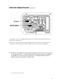
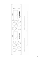
SOC 1.1 Stereo Optical Compressor
Users Manual
SOC 1.1 USERS MANUAL VERSION-4, DEC. 2009. CONTENTS COPYRIGHT BUZZ AUDIO 2001.
PO BOX 6677, TE ARO. WELLINGTON, NEW ZEALAND. VOICE/FAX 64+4+385-2478.
www.buzzaudio.com
email [email protected]
Welcome…
Thank you for choosing the Buzz Audio SOC 1.1 Stereo Optical Compressor.
In this manual you will find important information regarding the use of your
SOC 1.1 and we suggest that you do read it before using the unit to become
familiar with the controls and their functions.
If after unpacking the SOC 1.1 you find any damage you should contact
your dealer or supplier immediately for advice on what to do.
We also suggest you retain the original packaging at least during the
warranty period in case you need to return the unit for service, however we
are confident this will not be necessary!
Contents…
1] The Mains Input - page 2.
2] Connections - page 3.
3] Controls and Indicators - page 4.
4] Tips for Use – page 7.
5] Service – page 9.
6] Specifications – page 9.
7] Internal Adjustments – page 10.
8] Warranty Information – page 12.
9] Recall Sheet – page 13.
SOC 1.1 USERS MANUAL VERSION-4 PAGE 1
1] The Mains Input
As a safety precaution your SOC 1.1 is shipped without a mains fuse fitted.
Before use, you must select the correct mains voltage for your local supply
on the rear panel and fit the correct mains fuse type into the fuse draw for
that voltage.
•
Setting the Voltage Selector…
You will need a flat blade screwdriver.
If your mains voltage is 110V to 120V set the rear panel voltage selector to 120V.
If your mains voltage is 220V to 240V set the rear panel voltage selector to 240V.
POWERING UP THE SOC 1.1 WITH THE WRONG VOLTAGE SETTING MAY CAUSE
SEVERE INTERNAL DAMAGE !!
•
Selecting the Correct Fuse…
In the supplied accessories bag you will find;
2x 1.5 Amp slow blow fuses, FIT for 220V to 240V.
2x 2.5 Amp slow blow fuses, FIT for 110V to 120V.
Slide out the fuse draw above the IEC power inlet and insert the appropriate fuse into the
carrier clip. Note there is also a position in the carrier for a spare fuse (the square tube bit)
and we suggest you store the second supplied appropriate fuse here.
•
Please Note…
Fitting the wrong fuse may result in the fuse blowing on power up or inadequate protection.
Fitting fast blow type fuses may also result in the fuse blowing on power up.
Your dealer may have already set all this up for you but it pays to check it before powering
up the SOC 1.1.
SOC 1.1 USERS MANUAL VERSION-4 PAGE 2
2
2] Connections
•
Audio Input.
The XLR female style input connector is wired as follows;
Pin 1 = Signal Ground (common)
Pin 2 = Signal Hot (+)
Pin 3 = Signal Cold (-)
•
Audio Output.
The XLR male style output connector is wired as follows;
Pin 1 = Signal Ground (common)
Pin 2 = Signal Hot (+)
Pin 3 = Signal Cold (-)
Both inputs and outputs are electronically balanced. The standard operating input sensitivity
for the SOC 1.1 is +4dBu (1.23V rms). This input level will give a 0 V.U. reading on the meters.
Other input sensitivities (eg, -10dBv) can be supplied from the factory.
•
Note…
The pin 1 Signal Ground connection is intended for connecting cable SHIELDS. When
connecting the SOC 1.1 to other devices, it is not always necessary to connect the shield at
both ends of the cable. This may help prevent earth loops occurring.
The normal practice is to connect the shield at the receiving (input) end and leave the send
(output) end “earth free”.
FOR SAFETY REASONS THE SOC 1.1 SHOULD ALWAYS BE MAINS
EARTHED. RESIST THE TEMPTATION TO REMOVE THE EARTH TO
GET RID OF HUM. FIX IT ELSEWHERE IN THE SYSTEM.
SOC 1.1 USERS MANUAL VERSION-4 PAGE 3
3
3] Controls and Indicators
•
DRIVE
This control adjusts the amount of signal sent to the side chain circuit and therefore the
amount of gain reduction applied. Think of it as a Threshold control as found on other
compressors. Clockwise rotation increases the amount of gain reduction.
•
OUTPUT dB
Adjusts the post compression make up gain to bring the output level back up to the desired
level. Variable from 0dB to +15dB gain.
•
ATTACK.
This switch has 3 positions. See Tips for Use for more info.
Slow – The attack time of the compressor = approx 70mS and varies slightly depending on
the amount of gain reduction. The attack time speeds up with greater gain reduction. This
setting is great for getting extra “front” on a percussive sound.
Auto – Attack time of the SOC 1.1 is totally dependant on the program material and the
amount of gain reduction occurring. This is perhaps the most “musical” mode when using
low Ratio settings and could also be named the “Classic Sound” setting.
Fast - The attack time of the compressor is 1mS, and also varies with program material.
Percussive signals will provide a further increase in speed, the SOC 1.1 will attack faster.
Recommended when using 10:1 or 20:1 Ratio setting under heavy gain reduction.
•
RATIO
This control adjusts the change in gain reduction for a given change in input signal level. For
example, in position 5 a 5dB increase in input signal level will yield a 1dB increase in output
signal level, being a Ratio of 5:1. Because the SOC 1.1 has a soft knee characteristic, the
Ratio value selected is the ultimate achieved and will appear to be softer at threshold. Also
see page 7.
SOC 1.1 USERS MANUAL VERSION-4 PAGE 4
4
Controls and Indicators continued…
• RELEASE.
1-2-4-8-16 - sets the release time of the compressor in 100’s of mS from 20dB gain
reduction. For example, selecting setting 4 means the compressor will take 400mS to return
to 0dB gain reduction from an initial 20dB of gain reduction. Note however the actual
release time will vary slightly depending on the amount of gain reduction with the SOC 1.1
taking longer to release from heavy gain reduction.
Auto – In this position, the release is program dependent. The compressor will release from
fast transient signals quickly, but will maintain a slower release time with more continuous
signals. Also see Tips for Use for more info on the release control.
•
METER
This switch has 3 positions.
I/P – The VU meter monitors the audio input signal as applied to the input connector.
G/R – The meter displays the amount of gain reduction or compression applied to the audio
input signal. Note that the meter provides an “indication” of the amount of gain reduction
and does not accurately display fast transient attacks.
O/P – The VU meter monitors the audio output signal post the Output gain make up control.
•
NOTE; the operation of the meter is unaffected by the Bypass switch. When
monitoring I/P or O/P the meter is calibrated to +4dBu = 0 V.U. (standard model,
other calibrations available to order).
•
BYPASS/IN
In the up position, this switch provides a hard relay bypass of audio input to audio output with
no electronics in the signal path. Useful in comparing the compressed to un-compressed
signal. The SOC 1.1 is operational when IN is selected (obviously).
SOC 1.1 USERS MANUAL VERSION-4 PAGE 5
5
Controls and Indicators continued…
•
SEPARATE-LINK A/B
In Separate mode, the SOC 1.1 operates as two completely individual mono channels.
In Link A/B mode, the compressor side chains are linked to provide stereo tracking. This
mode is used to prevent the stereo “image” shifting if a loud sound appears only in one
channel of a stereo mix. For example, if this mode is not selected, a loud floor tom panned
hard left in a mix may cause the output stereo image to move towards the right as more
gain reduction occurs in the left channel than the right.
Important Note: Unlike some other VCA based compressors, all controls remain
operational. You MUST still set up BOTH A and B channel’s controls in Link A/B mode, usually
with identical settings for stereo program, fine tuned by ear.
•
POWER
Fairly obvious, turns the SOC 1.1 on or off and a little yellow LED tells you when you’ve done
this correctly! Automatic bypass of the unit is initiated when the power is switched off or if the
mains power is lost.
Please read the following Tips for Use section for more help on using your
SOC 1.1.
SOC 1.1 USERS MANUAL VERSION-4 PAGE 6
6
4] Tips for Use
Unlike some other audio compressors that are designed to “text book” parameters, the Buzz
Audio SOC 1.1 possesses a unique “musically transparent” soft knee compression
characteristic. It is equally at home providing gentle level control of acoustic sources
through to full on squash for “in your face” lead vocals. The following operational tips will
help in getting the best out of your unit, but the final word has to be – use your ears!
•
Slow Attack.
The SLOW position is useful in obtaining more fronts from percussive sounds. For example, a
snare that has no “stick” sound may be improved by gentle compression with a slow attack
and quick (1 or 2) release time. The initial transient of the snare is allowed to pass unaffected
but compression is applied to the “tail” of the sound, bringing the “stick” forward.
•
Auto Attack.
Best choice for low ratio light compression of sources like acoustic guitar, bass guitar, vocals
and even stereo mixes. The adaptive nature of the auto position prevents “pumping” and
really is the “classic” sound of LDR type compressors.
•
Fast Attack.
Generally, when high ratio’s and heavy compression are applied to vocals, the fast attack
position is the best choice to prevent sibilance problems. When compressing a stereo mix,
the fast position will help control peaks in the program material getting through.
•
Release Times.
Selecting the most appropriate compressor release time is best achieved by ear but here
are some guidelines.
Stereo Mixes – generally a release time of 400mS (number 4 on the dial) or Auto is
appropriate, but really does depend on the type of program material.
Bass Sounds - Faster release times will distort the bass register as the compressor actually
starts to track the bass frequencies, however in saying that, the effect of a fast release may
be the sound you’re looking for!
Vocals & Voice Overs – under heavy gain reduction, 100mS release (number 1 on the
dial) will prevent “pumping” and missing phrases due to the compressor still releasing from a
loud patch. If using a low ratio and light compression, slower release or the Auto position
may sound warmer. Again, experimentation is the key.
Auto mode – a clever little circuit inside the SOC 1.1 provides a quick release from
transients and peaks whilst maintaining a slow release on overall program. This is similar to
an automatic gain control (AGC) type action, although a lot more intelligent in it’s response.
SOC 1.1 USERS MANUAL VERSION-4 PAGE 7
7
Tips for Use continued…
•
SOC 1.1 Ratios.
The following graph shows the input to output relationship of the four ratios with the Drive
control set fully clockwise.
From this graph we see that for lower ratios settings (2:1 and 5:1), the ratio is ultimately
achieved only after another further 10dB of gain reduction from threshold, (threshold
meaning 0dB gain reduction). For higher ratios, (10:1 and 20:1) the ultimate ratio is
achieved within approx. 10dB and 5dB respectively.
This area of the graph represents the “soft knee” of the SOC 1.1 compression characteristic
and is an important feature of it’s design.
Choosing a low ratio settings for gentle control of level and thereby increasing the loudness
of a sound within a mix is possible without signal degradation and minimal colouration. On
the other hand, with higher ratio settings, a sound may be “clamped” or levelled whilst still
retaining some audible dynamic.
Note that the 20:1 ratio setting is virtually hard limiting in that a 20dB input change only results
in a 1dB output change.
•
Cleaning.
Clean the SOC 1.1 with a damp cloth and a little detergent. Do not use solvents or isopropyl
alcohol, it may damage the finish.
SOC 1.1 USERS MANUAL VERSION-4 PAGE 8
8
5] Service
Should you experience any technical problem with your SOC 1.1, contact your dealer or
Buzz Audio for recommendations on what to do. The modular nature of the SOC 1.1
construction means most electronic faults can be easily repaired by swapping circuit
boards.
For on line support visit our web site; www.buzzaudio.com
Buzz Audio, 77 Kent Tce, PO Box 6677, Te Aro, Wellington,
New Zealand. Voice/Fax 64+4+385-2478.
Email; [email protected]
6] Specifications
Max Input/Output Level = +23.5dBu.
Measured with 2k ohm load and 0dB output gain makeup.
Frequency Response = 4Hz to 250kHz.
-3dB points with no gain reduction.
Harmonic Distortion = less than 0.008%.
Measured 100Hz to 10kHz with no gain reduction.
Harmonic Distortion = less than 0.03%.
Measured 100Hz to 10kHz with 20dB gain reduction, Attack-AUTO, Release-16
Residual Output Noise = typically -90dBu, -100dBu A wtg.
No gain reduction, 0dB output gain makeup, 150R input source impedance.
Channel to Channel Crosstalk = below noise.
150R source Z on measured CH-A, +20dBu applied to CH-B, 100Hz to 10kHz.
Standard Operating Level = +4dBu = 0 VU meter display.
Other sensitivities can be supplied from the factory.
Power Requirements = 230 or 115 Volts (selectable on rear).
Package = 2U rack mount, 482W x 44.5H x 250D (mm).
Weight = 7kgs.
SPECIFICATIONS SUBJECT TO CHANGE WITHOUT NOTICE.
SOC 1.1 USERS MANUAL VERSION-4 PAGE 9
9
7] Internal Adjustments
The SOC 1.1 has a number of internal trimpots to set up the ratio calibration and the gain
reduction metering circuit. Full line up is a relatively complicated procedure beyond the
scope of this manual, and should only be required if a LDR/LED module is replaced.
Instructions for full alignment can be obtained by contacting your supplier or Buzz Audio
directly.
•
VU Meter Calibration.
IMPORTANT NOTE – the LDR module inside the SOC 1.1 is sensitive to external light so do not
perform any alignments in high light conditions. A black cloth should be laid over the LDR
modules (little black boxes with a dab of paint) to prevent light entering.
See page 10 for the location of trimpots.
• Set the front panel controls as follows:
Drive = 0 (fully anti-clockwise)
Output = 0dB (fully anti-clockwise)
Attack = Auto (middle)
Ratio = 2 (fully anti-clockwise)
Release = Auto (fully clockwise)
Meter = I/P (up)
Bypass = Bypass (up)
Link = Separate (up)
1] With the power off, remove the top panel and locate the Meter board directly behind the
switch board of the SOC 1.1 channel. Please observe safety precautions when removing the
top cover.
2] Adjust the V.U. meter mechanical zero (little black screwdriver adjustment on the rear of
the meter barrel) for a mechanical zero.
3] Connect an accurate audio voltmeter to the SOC 1.1 output. Feed into the input a 1kHz
+4dBu (1.23V rms) signal. The level on the external audio voltmeter should read +4dBu.
4] Apply power and switch the Bypass switch to IN, the external audio voltmeter should also
read +4dBu (+/- 0.5 dB)
5] Locate the VU CAL trimpot on the meter board and adjust it for
0 V.U. indication on the SOC 1.1 V.U. meter. Change the Meter switch to O/P and check
that the SOC 1.1 meter also indicates 0 V.U. (+/- 0.5dB).
6] Remove the input signal, change the Meter switch to G/R and locate the METER ZERO
trimpot. Adjust this to obtain a 0 V.U. indication.
•
Problems?
Contact your dealer or Buzz Audio.
SOC 1.1 USERS MANUAL VERSION-4 PAGE 10
10
Internal Adjustments continued…
Locating the “VU CAL” and “METER ZERO” trimpots on the Meter board directly behind the
front panel control board.
These are the only trims that may need adjustment from time to time. All other trims are
factory set to match the LDR modules installed and do not need routine alignment.
•
PLEASE do not adjust any other internal trimpots unless you have a copy of
the Buzz Audio SOC 1.1 Audio Alignment Instructions and are confident in
your ability to correctly set up the device. To obtain these instructions
please contact your dealer or Buzz Audio.
SOC 1.1 USERS MANUAL VERSION-4 PAGE 11
11
8] Warranty Information
We are confident that you will receive many years of trouble free operation from your unit. If
however you experience any technical problem with your SOC1.1, contact your dealer or
Buzz Audio for recommendations on what to do. The modular nature of the SOC
construction means most electronic faults can be easily repaired by swapping the circuit
board.
For on line support visit our web site; www.buzzaudio.com
Buzz Audio, 77 Kent Tce, PO Box 6677, Te Aro, Wellington, New Zealand. Voice/Fax
64+4+385-2478.
Email; [email protected]
•
Disclaimer
Buzz Audio is not liable for any damage to microphones, amplifiers, consoles, speakers or
any other equipment and/or electric shock to humans that is caused by negligence or
improper installation and/or use of the SOC1.1 Stereo Optical Compressor.
•
Standard Product Warranty
Buzz Audio guarantees the SOC1.1 Stereo Optical Compressor to be free of defective
materials and/or workmanship for a period of 1 year (12 months) from the date of sale, and
will replace defective parts and repair malfunctioning products under this warranty when the
defect occurs under normal installation and use – provided the unit is returned to our factory
(or duly authorised service centre) via prepaid transportation with a copy of the proof of
purchase, ie, sales receipt. This warranty provides that examination of the returned product
must indicate, in our judgement, a manufacturing defect. This warranty does not extend to
any product that has been subjected to misuse, neglect, accident, improper installation, or
where the date code has been removed or defaced. The standard warranty is NOT
transferable.
•
Product Warranty Extension
The above Warranty may be extended to a period of 2 years (24 months) from date of sale
provided the enclosed Warranty Registration card is completed and returned to the office of
Buzz Audio within 4 weeks (28 days) from purchase date. Alternatively, you may Register your
purchase on-line at our web-site www.buzzaudio.com. The Extended Warranty is
transferable.
Your dealer is…
SOC 1.1 USERS MANUAL VERSION-4, JAN. 2009. CONTENTS COPYRIGHT BUZZ AUDIO 2001.
PO BOX 6677, TE ARO. WELLINGTON, NEW ZEALAND. VOICE/FAX 64+4+385-2478.
www.buzzaudio.com
email [email protected]
12
13