1
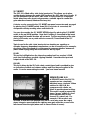
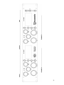
SOC-20
Stereo Optical Compressor
Users Manual
SOC-20 USERS MANUAL VERSION-1, AUGUST 2011. CONTENTS COPYRIGHT BUZZ AUDIO LTD 2011.
PO BOX 6677, TE ARO. WELLINGTON, 6141 NEW ZEALAND. PH. +64-4-472-3084
www.buzzaudio.com
email [email protected]
Welcome…
Thank you for choosing the Buzz Audio SOC-20 Stereo Optical Compressor. In
this manual you will find important information regarding the use of the SOC
and we suggest you do read it before using the unit to become familiar with all
the controls and their function.
If after unpacking the SOC you find any damage to the unit you should contact
your dealer or supplier immediately for advice on what to do.
We also suggest you retain the original packaging at least during the warranty
period in case you need to return the unit for servicing, however we are
confident this will not be necessary!
Contents
1] Installation Precautions..........................................................3
2] The Mains Input.........................................................................3
3] Audio Connections...................................................................3
4] Controls and Indicators..........................................................4
5] Specifications ..............................................................................8
6] Service Information...................................................................8
7] Warranty Information ..............................................................9
8] Recall Sheet ..............................................................................10
②
1] Installation Precautions
The SOC-20 compressor uses discrete Class A amplifiers and these plus the
power supply do generate a fair amount of heat. Normally the SOC can be
mounted into a rack without any special ventilation need. If there are other
units in the rack that also run hot, it may be necessary to allow for ventilation
gaps between the units to avoid over heating. Excessive heat for long periods
can shorten the life of all electronic devices.
2] The Mains Input
The SOC-20 mains input can be set to run from 110V or 230V. On the rear
panel you will find a circular voltage selector switch to set this. Generally the
SOC mains voltage is set for the country to which it has been initially sent, but
before powering up the unit, please check the voltage selector.
POWERING UP THE SOC WITH THE WRONG VOLTAGE SETTING MAY CAUSE
BURN OUT OF THE POWER TRANSFORMER!
It is also important to fit the correct mains fuse. Below the IEC inlet you will see
the fuse draw. Using a small flat blade screwdriver, you can flick open the
draw and change the fuse if required. The fuse draw also has a place to hold
a spare fuse (the square tube).
The correct fuses are;
110V = 2 amp slow blow
230V = 1 amp slow blow
These fuses will either be fitted in the fuse draw, and/or supplied in an
accessory bag with the SOC.
3] Audio Connections
On the rear panel of the SOC you will find the XLR input and output connectors.
All these connectors are wired as follows;
Pin 1 = Chassis Ground
Pin 2 = Signal + (hot)
Pin 3 = Signal – (cold)
Note that the pin1 connection of these connectors is not part of the audio path,
and is provided to shield the interconnecting cable. Leaving pin 1 free at one
end of the cable can help reduce earth loops with other equipment as only the
signal hot and signal cold are required.
Generally speaking, keeping the signals balanced is a good idea, but all the
inputs and outputs of the SOC-20 will accept unbalanced lines and signals if
you have no other choice.
③
There are two audio paths provided, the LINE path and the S/C (side chain) path.
The main audio input and output connect to the LINE connectors and if you
wish to insert another device into the SOC-20 side chain (more on this later),
use the S/C INSERT connectors.
4] Controls and Indicators
The SOC-20 has two channels with identical controls. By now you might have
guessed that the SOC-20 can be used as 2 mono audio compressors, a stereo
compressor (left/right) and stereo mid/side compressor. In either case the
controls of the two channels are the same.
DRIVE
This control adjusts the amount of signal sent to the side chain circuit and
therefore the amount of gain reduction (or compression) applied to the input
signal. Clockwise rotation increases the amount of gain reduction.
OUTPUT dB
Adjusts the post compression make up gain to bring the output level back up to
the desired volume. Clockwise rotation increases gain from 0dB to +15dB gain.
ATTACK
This switch has 5 positions and adjusts the time taken (in milli-seconds) for the
SOC to respond to signals that exceed the threshold (as set with the Drive
control). This is the time taken to achieve 20dB of gain reduction. The “A”
position is Auto where the attack time is totally dependant on the program
material and the amount of gain reduction occurring. This is perhaps the most
“musical” mode and could also be called the “Classic Sound” setting.
RELEASE
This switch sets the time taken (in 100’s of mS) for the SOC-20 to release from
20dB gain reduction. For example, selecting setting 4 means the compressor
will take approx 400mS to return to 0dB gain reduction from an initial 20dB of
gain reduction. “A” stands for Auto and in this position a clever little circuit is
④
engaged which allows the SOC to release from fast transient signals quickly,
but maintain a slower release time with more continuous signals such as low
frequencies or bass.
RATIO
This switch sets the amount of gain reduction (or compression) for a given
change in input signal level. For example, in position 6, a 6dB increase in input
signal level will yield a 1dB increase in output signal level, being a Ratio of 6:1.
Because the SOC-20 has a soft knee characteristic, the Ratio value selected is
the ultimate achieved after approx 10dB of gain reduction, so the Ratio will be
softer with small amounts of gain reduction. This is the characteristic that
makes the SOC sound so unique.
BYPASS
In the up position, this switch provides a hard relay bypass of audio input to
audio output with no electronics in the signal path. This is useful in comparing
the compressed to un-compressed signal. When using the SOC with stereo
signals, both A and B channels’ bypass switches would be operated together
for a meaningful result.
I/P–G/R–O/P
This switch is used to monitor signals on the VU meter. At I/P position the VU
meter monitors the audio input signal as applied to the LINE input connector.
At G/R position the meter displays the amount of gain reduction or compression
applied to the audio input signal. Note that the meter provides an “indication”
of the amount of gain reduction and does not accurately display fast transient
attacks. At O/P position the VU meter monitors the LINE output signal post the
Output gain make up control. The operation of the meter is unaffected by the
Bypass switch.
S/C HPF
When this switch is down (IN) a 12dB per octave high pass filter at 170Hz is
placed into the SOC side chain path. This has the affect of reducing
compressor sensitivity at low frequencies and is useful when you wish to retain
bass information but still compress higher frequencies.
⑤
S/C INSERT
The SOC-20 is fitted with a side chain insert point. This allows you to place
another device between the audio LINE input and the SOC side chain circuits. (If
you are unfamiliar with the term “side chain” it is the circuit in a compressor
which takes the audio signal and generates a suitable signal to control the
gain reduction element, whatever that may be).
A device can be connect to the S/C INSERT rear panel connectors and engaged
by placing the S/C INSERT switch down (IN). If no device is connected, the
compressor will stop working when switched to IN.
You can also monitor the S/C INSERT RETURN signal by placing the S/C INSERT
switch to the up (MON) position. Note that if nothing is connected to the insert
return input, the monitor function will not work. To allow monitoring of the side
chain in MS mode, use a patch cable to connect S/C Insert Send to the S/C
Insert Return.
Typical uses for the side chain insert point are inserting an equalizer so
complex frequency dependant compression can be accomplished, for example,
de-essing. Using the sound of an instrument to compress another instrument
(often called keying) using the insert return as the key input.
PK LED
This red led will light when the internal operating level has reached +22dB
peak level indicating a possible clipping situation. It monitors the input and
output circuits of the SOC-20.
LDR LED
This led is driven by the SOC side chain control signal and is provided to give
an indication of attack and release settings and how they are applied to the
audio. It can be mesmerising to watch – you have been warned!
SEPARATE-LINK A/B
In SEPARATE mode, the SOC-20
operates as two completely
individual mono channels. When
switched to LINK A/B, the
compressor side chains are
linked to provide stereo tracking.
This mode is used to prevent the
stereo “image” shifting if a loud
sound appears only in one
channel of a stereo mix. For
example, if this mode is not
selected, a loud floor tom panned hard left in a mix may cause the output
stereo image to move towards the right as more gain reduction occurs in the
left channel than the right (when used in Stereo Mode of course).
⑥
Note that unlike some VCA based compressors, all controls remain operational
in LINK A/B mode. You MUST still set up BOTH A and B channel’s controls
usually with identical settings for stereo program (non MS mode), and perhaps
then fine tuned by ear.
MODE STEREO-MID/SIDE
As mentioned earlier, the SOC-20 can be used as two mono compressors and
a stereo mix (left/right) compressor. For these modes, this switch should be in
the up position (STEREO). Note this is a locking toggle and you need to pull out
the lever to operate it.
When switched to MID/SIDE (switch down) the SOC-20 sum and difference
amplifier circuits are engaged. These circuits take the stereo left/right input (as
applied to the Channel A and B Line Input connectors) and generate a sum
signal (audio that is common to left and right) and a difference signal (signals
that are not common). These signals are referred to as MID and SIDE.
The MID signal is fed into Channel A’s compressor and the SIDE signal to
Channel B’s compressor, then back to another set of sum and difference
amplifiers to regenerate the stereo signal. This allows you to compress the MID
and SIDE signals separately and is an extremely powerful tool for processing
stereo sounds. Note the MS mode will only work with stereo signals.
You can monitor the generated MID and SIDE signals with the S/C MON
function (use a patch cord between S/C INSERT SEND and RETURN connectors if
no insert device is connected). The MID and SIDE signals pre-compression are
outputted at the S/C INSERT SEND connectors.
•
Please Note! When switching the MODE switch, a large amount of
reconfiguration takes place within the SOC20 audio circuits and this will
cause an audible click. We could have fitted a plethora of coupling
capacitors to reduce this click but this caused to much signal
degradation. The locking toggle prevents accidental operation.
POWER ON
This switches the mains power to the SOC-20 on and off. A yellow led tells you
when it’s on. The SOC bypass relays are engaged for a few seconds at power
up.
⑦
5] Specifications
Maximum Input Level Line; +32dBu
Maximum Output Level Line; +27dBu
Maximum Input/Output Level S/C Insert; +22dBu
Noise; -95dBu Stereo Mode; -90dBu M/S Mode
(measured with no make up gain and A Weighted).
Gain; variable 0dB to +15dB
Operating Level; +4dBu = 0VU on meter
Frequency Response;
3Hz to 120kHz measured with +10dB gain and no gain reduction.
Harmonic Distortion no gain reduction;
0.08% @ 100Hz, 0.025% @ 1kHz, 0.02% @ 10kHz, 0.05% @ 100kHz
Harmonic Distortion with 20dB gain reduction (Attack AUTO, Release 16);
0.1% @ 100Hz, 0.06% @ 1kHz, 0.04% @ 10kHz
Harmonic Distortion with 20dB gain reduction (Attack AUTO, Release AUTO
2%@ 100Hz,
Mains Voltage; 110-115Vac or 220-240Vac switchable.
6] Service Information
We are confident that you will receive many years of trouble free operation from
your unit. If however you experience any technical problem with your SOC-20,
contact your dealer or Buzz Audio for recommendations on what to do. The
SOC is constructed with non-surface mount serviceable parts, this means most
electronic faults can be easily repaired.
Please note there are no user serviceable parts inside the SOC-20 and
attempting any internal adjustments without the alignment instructions and
correct test equipment may render the unit un-operational.
For on line support visit our web site www.buzzaudio.com
Buzz Audio Ltd, PO Box 6677, Wellington 6141, New Zealand.
Phone +64-(0)4-472-3084. Email; [email protected]
⑧
7] Product Warranty
• Disclaimer
Buzz Audio Ltd is not liable for any damage to microphones, amplifiers,
consoles, speakers or any other equipment and/or electric shock to humans
that is caused by negligence or improper installation and/or use of the SOC-20
Stereo Optical Compressor.
• Standard Product Warranty
Buzz Audio Ltd guarantees the SOC-20 Stereo Optical Compressor to be free of
defective materials and/or workmanship for a period of 1 year (12 months) from
the date of sale, and will replace defective parts and repair malfunctioning
products under this warranty when the defect occurs under normal installation
and use – provided the unit is returned to our factory (or duly authorised service
centre) via prepaid transportation with a copy of the proof of purchase, ie, sales
receipt. This warranty provides that examination of the returned product must
indicate, in our judgment, a manufacturing defect. This warranty does not
extend to any product that has been subjected to misuse, neglect, accident,
improper installation, or where the date code has been removed or defaced.
The standard warranty is NOT transferable.
• Product Warranty Extension
The above Warranty may be extended to a period of 2 years (24 months) from
date of sale provided the enclosed Warranty Registration card is completed and
returned to the office of Buzz Audio Ltd within 4 weeks (28 days) from purchase
date. Alternatively, you may Register your purchase on-line at our web-site
www.buzzaudio.com. The Extended Warranty is transferable.
SOC-20 USERS MANUAL VERSION-1, AUGUST 2011. CONTENTS COPYRIGHT BUZZ AUDIO LTD 2011.
PO BOX 6677, TE ARO. WELLINGTON, 6141 NEW ZEALAND. PH. +64-4-472-3084
www.buzzaudio.com
email [email protected]
⑨
⑩