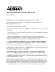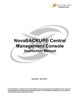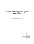
1
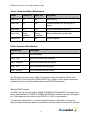
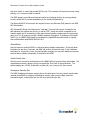
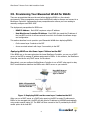
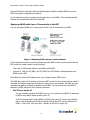
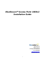
BlueSecureTM Access Point 1800v2
Installation Guide
Bluesocket, Inc
10 North Avenue
Burlington, MA 01803 USA
+1 781-328-0888
www.bluesocket.com
Document Version 1.0
1
BlueSecure™ Access Point 1800 Installation Guide
Copyright Notice
Copyright © 2010 Bluesocket, Inc.
All rights reserved. No part of this document may be reproduced in any form or by
any means, electronic or manual, including photocopying without the written
permission of Bluesocket, Inc. The products described in this document may be
protected by one or more U.S. patents, foreign patents, or pending patents. This
document is provided “as is” without warranty of any kind, either express or
implied, including, but not limited to, the implied warranties of merchantability,
fitness for a particular purpose, or non-infringement. This publication could include
technical inaccuracies or typographical errors. Changes are periodically added to
the information herein; these changes will be incorporated in new editions of the
document. Bluesocket inc. may make improvements or changes in the products or
the programs described in this document at any time.
Trademarks
Bluesocket, The Bluesocket Logo, Secure Mobility, BlueView, and BlueSecure are
trademarks or registered trademarks of Bluesocket, Inc. Bluetooth is a trademark
owned by Bluetooth SIG, Inc., U.S.A. and is licensed to Bluesocket, Inc. All other
trademarks, trade names and company names referenced herein are used for
identification purposes only and are the property of their respective owners.
2
BlueSecure™ Access Point 1800 Installation Guide
Table of Contents
I. Overview ............................................................................................................................4
II.
Familiarizing Yourself with the BSAP-1800 Hardware................................................5
III.
Provisioning Your Bluesocket WLAN for BSAPs ..........................................................8
IV.
Selecting a BSAP Installation Location ......................................................................11
V. Wall Mounting the BSAP-1800 .......................................................................................12
VI.
Ceiling Mounting Kit for the BSAP-1800....................................................................13
VII. Connecting and Powering the BSAP ..........................................................................16
VIII.
Using the BSAP Command Line Interface (CLI) ...................................................18
IX.
General Specifications.................................................................................................24
3
BlueSecure™ Access Point 1800 Installation Guide
I. Overview
The BlueSecure Access Point 1800 is an 802.11n-based “thin” access point that works in
conjunction with BlueSecure Controllers (BSCs) for enterprise wireless LAN (WLAN)
deployments. The BlueSecure Access Point 1800 features dual radios supporting 802.11a/n and
802.11b/g/n with a high performance internal antenna.
BSAPs are simple to configure and require only minimal provisioning to make them operational
on a WLAN secured and managed by a BlueSecure Controller
BSAPs can be directly attached to any existing Layer-2 or Layer-3 Ethernet switch and
communicate with the BSC across any subnet boundary. Once the BSAP has discovered and
established Layer-2 or Layer-3 communication with its home (i.e., host) BlueSecure Controller,
advanced configuration and provisioning may be applied either to individual BSAPs or globally
across the entire WLAN using the BSC’s web-based Administrator Console.
Figure 1: BSAPs Automatically Discover BSCs across L2/L3 Networks
Once the BlueSecure Access Point has downloaded its configuration from the BlueSecure
Controller, the BSAP initializes its radios and begins servicing clients.
This guide provides complete installation procedures for your BSAP including:
•
Familiarizing yourself with the BSAP hardware
•
Provisioning your Bluesocket WLAN for BSAPs
•
Selecting a BSAP installation location
•
Connecting and powering the BSAP
•
Using the BSAP command line interface (CLI)
4
BlueSecure™ Access Point 1800 Installation Guide
II. Familiarizing Yourself with the BSAP-1800 Hardware
Make sure that you receive the following items in the package:
1
1
8
1
-
BSAP-1800
Wall-mounting Hardware (Wall/table bracket/stand, 4 screws, 4 wall anchors)
Adhesive rubber feet
Ceiling mounting Hardware
Please spend a few minutes familiarizing yourself with the BSAP-1800 enclosure.
Antenna
The BSAP-1800 has a high-performance internal antenna (no external antenna is required)
LED Indicators
The following LED indicators are located on the top of the BSAP-1800 housing.
5
BlueSecure™ Access Point 1800 Installation Guide
Table 1: Status and Radio LED Definitions
Status
2.4Ghz LED
5Ghz LED
Description
Yellow Solid
Off
Off
Initial power-up
Green Solid
Off
Off
Initializing software and acquiring an IP
address
Green Blink
Off
Off
Discovering Bluesocket controller
Green Solid
Green
Solid/Blink
Green
Solid/Blink
Radios Activated and passing traffic
Orange Solid
Off
Off
Software Upgrade
Table 2: Network LED Definitions
Network LED
Description
Off
No Link Detected
Amber - ON
10/100 Link Detect with No Activity
Amber - Blinking
10/100 Link Detect with with Activity
Green - ON
1000 Link Detect with No Activity
Green - Blinking
1000 Link Detect with with Activity
The BSAP does not have a power switch. It’s powered on when connected to a Power over
Ethernet (PoE) from a PoE injector (BSAP-POE-001-00-0), switch or other network device that
supplies power over the network cable based on the IEEE 802.3af standard.
Ethernet/PoE Connector
The BSAP-1800 has one auto-sensing 10BASE-T/100BASE-TX/1000BaseT RJ-45 connector that
can be attached directly to 10BASE-T/100BASE-TX/1000BaseT switches to provide a full-duplex
link. These segments must conform to the IEEE 802.3 or 802.3u specifications.
This connector uses an MDI (i.e., internal straight-through) pin configuration. You can use
straight-through twisted-pair cable to connect this port to most network interconnection devices
6
BlueSecure™ Access Point 1800 Installation Guide
such as a switch or router that provide MDI-X ports. This connector will sense the correct wiring
polarity, so no crossover cable is required.
The BSAP appears as an Ethernet node and performs a bridging function by moving packets
from the wired LAN to remote workstations on the wireless infrastructure.
The Ethernet/PoE RJ-45 connector also supports Power over Ethernet (PoE) based on the IEEE
802.3af standard.
802.3af specifies Power over Ethernet for “mid-span”, where a PoE injector is located in the
path between the network and the AP, as well as “PSE”, where the power is supplied by the
network switch the AP is attached to. Mid-span devices typically provide power on the unused
pairs (4+5 & 7+8) and only provide 100Mbps maximum throughput. To realize the full benefit
of 802.11n, the BSAP-1800 should be connected to a Gigabit Ethernet PoE switch or injector,
such as Bluesocket model BSAP-POE-001-00-0.
Reset Button
Use this button to reset the BSAP or restore its factory default configuration. If you hold down
the button for less than 5 seconds, the BSAP will perform a hardware reset. If you hold down
the button for 5 seconds or more, any configuration changes you may have made are removed,
and the factory default configuration is restored to the BSAP.
Serial Console Port
Use this port to connect a console device to the BSAP-1800 via special rollover serial cable. The
console device can be a laptop running a program like Tera-Term or Hyper-terminal. The
default settings are 115200, 8 data bits, no parity (N), and 1 stop bit (no flow control).
Kensington Security Slot
The BSAP includes a Kensington security slot on the side panel. You can prevent unauthorized
removal of the BSAP by wrapping a Kensington security cable (not provided) around an
unmovable object, inserting the lock into the slot, and turning the key.
7
BlueSecure™ Access Point 1800 Installation Guide
III. Provisioning Your Bluesocket WLAN for BSAPs
There are prerequisites that must be met before deploying BSAPs in a live network
environment. These prerequisites ensure that the BSAPs are able to discover and connect to a
BlueSecure Controller. Implementing these prerequisites also relieves you from needing to
manually configure each BSAP-1800.
The deployment prerequisites for BSAPs are:
•
BSAP IP Address - Each BSAP requires a unique IP address.
•
Host BlueSecure Controller IP Address - Each BSAP also needs the IP address of
the host BSC to which it will connect and from which it will obtain its software image
and configuration.
This section describes how to provision your Bluesocket WLAN when deploying BSAPs:
•
On the same Layer-2 subnet as the BSC
•
Across a routed network with Layer-3 connectivity to the BSC
Deploying BSAPs on the Same Layer-2 Subnet as the BSC
If the BSAPs are on the same subnet as the home BlueSecure Controller, you can run a DHCP
server on the BSC to manage IP address assignment to BSAPs. In this scenario, the BlueSecure
Controller must be the only DHCP server for the subnet.
Alternatively, you can configure the BlueSecure Controller to run a DHCP relay agent to relay
DHCP communications between the BSAPs and a DHCP server on your network.
Figure 2: Deploying BSAPs on the same Layer-2 subnet as the BSC
When you run a DHCP server or a DHCP relay agent on the BSC to assign IP addresses to
BSAPs on the managed side, the BSC will also pass its IP address to the BSAPs automatically
using vendor-specific option 43. The BSAP will then connect to the IP provided by the DHCP
vendor option as its host BSC.
8
BlueSecure™ Access Point 1800 Installation Guide
See the BlueSecure Controller Setup and Administration Guide for detailed DHCP server and
DHCP relay agent configuration procedures.
In this deployment scenario, simply connect and power on the BSAPs. They will automatically
discover and communicate with their home BSC.
Deploying BSAPs with Layer-3 Connectivity to the BSC
You can also deploy BSAPs on a routed network with Layer-3 connectivity to the BSC
Figure 3: Deploying BSAPs across a routed network
In this deployment scenario, you must ensure that each BSAP is able to communicate with the
BSC across the routed network by verifying that:
•
There are no NAT devices between the BSAPs and the BSC
•
Protocol 97, UDP Port 53 (DNS), and TCP/UDP Port 33333 traffic is allowed between the
BSAPs and the BSC
Each BSAP will receive its IP address from your existing network DHCP server.
The BSAP also needs the IP address of the home BSC to which it will connect and from which it
will obtain its software image and configuration. Again, this is not needed if the BSAP is on the
managed side getting a relayed IP address from the BSC. You can provide the home BSC IP
address to a BSAP using one of the following methods:
•
DHCP Server Option 43
You can manually configure the DHCP server on your network to send BSC IP addresses
to BSAPs using DHCP vendor-specific option 43.
In DHCP requests sent from the BSAP, the BSAP uses option 60 Vendor class identifier
with a value of BlueSecure.AP1500 to identify itself to the DHCP server (Note that all
BSAPs —1500,1540, 1800, and 1800 —identify as AP1500 for option 43).
9
BlueSecure™ Access Point 1800 Installation Guide
Option 43 is configured as a comma-separated list, for example
"192.168.100.23,192.168.100.98,F192.168.100.25 "
Here the “F” denotes failover BSC. If all the primary BSCs fails (those without F
in front of their IP), the AP associates to the failover BSC.
Refer to the documentation supplied with your DHCP server when configuring vendorspecific option 43
•
DNS Server Configuration
BSAPs are factory configured with apdiscovery as the DNS hostname. You can configure
a DNS server on your network with an entry for apdiscovery with the home BSC
Controller IP address as the resolution.
To configure this, add a NAME record to the DNS server for apdiscovery (at the domain
server that the BAP will receive). Point this name to one or more BSC IP addresses
(managed, protected or VLAN depending on the network configuration).
So for example, if there are two BSCs (192.168.100.23 and 192.168.100.28), and the
domain is customer.com, add two NAME records to customer.com, for the name
apdiscovery.customer.com. One should resolve to 192.168.100.23 and one to
192.168.100.28. PTR (i.e., pointer) records are not needed for this portion of discovery.
10
BlueSecure™ Access Point 1800 Installation Guide
IV. Selecting a BSAP Installation Location
BlueSecure Access Points should be positioned for maximum throughput and range between
other BSAPs and wireless client devices. Normally, you should locate the BSAP on the ceiling
away from obstructions.
Range and performance are dictated by the distance between the BSAP and client radios, and
by obstacles that may be present in a specific building or office environment. The following
positioning guidelines are suggested:
•
Document all the BSAPs and client devices you wish to include in your wireless network.
Record the MAC address, serial number, and placement of each BSAP.
•
Wired LAN and power connections must be available for each BSAP at the desired
installation location. If a power outlet is not available near the access point, mid-span power
inserters are recommended.
•
If building blueprints or floor plans are available, use them to define potential client device
locations and likely roaming areas.
•
Identify possible obstacles or sources of interference that could affect signal strength (for
example, walls, metal objects).
•
Install the BSAP in an area where large steel structures such as beams, pillars, shelving
units, bookcases, and filing cabinets do not obstruct radio signals to and from the BSAP.
•
Once BSAPs have been installed and configured, use site survey and monitoring utilities
supplied with the client adapters to test signal strength at various locations. Modify the
positioning of the BSAPs and client stations as required for optimum performance.
11
BlueSecure™ Access Point 1800 Installation Guide
V. Wall Mounting the BSAP-1800
Use the white plastic mounting bracket that comes with the BSAP-1800 to install the AP on a
wall or electrical box. To mount the BSAP-1800, follow these steps:
1. Screw the mounting bracket to the wall or electrical box.
2. If mounting to drywall, use the four screws and the four wall anchors.
3. If mounting to a US electrical box, use two threaded screws and insert into the holes
marked “B” in the diagram shown below:
4. Connect the Ethernet cable (for power and network connection) to the port on the back of
the BSAP-1800.
12
BlueSecure™ Access Point 1800 Installation Guide
VI. Ceiling Mounting Kit for the BSAP-1800
The BSAP-1800 also comes with a ceiling mounting kit that enables the AP to be mounted on
the T-bar of standard drop ceilings.
To mount the BSAP-1800:
1. Attach the metal slider to the back of the BSAP-1800 using the two small screws. The slider
should still be able to slide after the screws are tightened.
Make sure that the slide is left in the same position as shown above.
2. Clip the metal ceiling bracket to a suitable location on the ceiling tile separator.
13
BlueSecure™ Access Point 1800 Installation Guide
3. Slide the moveable section into place and tighten the screw (found underneath) to secure it.
4. Position the BSAP-1800 so that the two tabs from the ceiling bracket locate in the slots
in the BSAP-1800 (A), then slide the slider across to lock the BSAP-1800 to the bracket
(B).
14
BlueSecure™ Access Point 1800 Installation Guide
15
BlueSecure™ Access Point 1800 Installation Guide
VII. Connecting and Powering the BSAP
Follow these instructions to connect your BlueSecure BSAP to your Bluesocket WLAN and then
power it up:
1.
Make a note of the 12-character MAC address and the serial number listed on the back of
the BSAP-1800 before mounting the BSAP to a wall or other surface. You will need this
information during configuration.
2.
Position the BSAP-1800 for best radio performance.
The BSAP-1800 should be place where it has the best unobstructed view of the coverage
area. If possible, mounting the BSAP-1800 on the ceiling will provide the best performance
in a typical office environment. For more information, please refer to Bluesocket’s web site.
3.
The BSAP derives its operating power directly from the RJ-45 connector when connected to
a device that provides IEEE 802.3af compliant Power over Ethernet (PoE).
Caution: If the BSAP is used in a medical environment, it must use an IEC/EN60601-1
compliant power adapter. See
16
BlueSecure™ Access Point 1800 Installation Guide
for a description of the IEC/EN60601-1 compliant power adapter.
Verify that the PWR LED stops flashing and remains on, and that the other status LEDs start
functioning as described in the section entitled
LED Indicators.
4. Connect the BSAP to your Bluesocket WLAN.
You can connect the BSAP-1800 to a 10/100/1000 Mbps Ethernet through a network device
such as a hub or a switch, or to a 1000BaseT Gigabit Ethernet interface. Connect the RJ-45
Ethernet connector on the BSAP’s back panel to your network using category 5 UTP
Ethernet cable. When the BSAP and the connected device are powered on, the BSAP’s
Ethernet Link LED should light indicating a valid network connection.
17
BlueSecure™ Access Point 1800 Installation Guide
VIII.
Using the BSAP Command Line Interface (CLI)
Note: Normally you will not need to access the BSAP CLI. In a properly provisioned Bluesocket
WLAN, the BSAP will automatically discover and communicate with the BSC. We recommend
that you use the CLI to configure the BSAP only in a lab or test environment, or where a predefined static IP address is desired.
You can connect to the serial console port or the Ethernet port to perform local configuration of
the BSAP using its command line interface (CLI). You can use the BSAP’s CLI to manually
configure:
•
BSAP’s Network Configuration (IP address, Default Gateway)
•
IP address of the home BSC from which the BSAP will download its configuration and
software image
•
Site survey mode
Accessing the BSAP CLI via serial port
Connect the special serial DB-9 to RJ-45 serial cable (rollover cable) to the BSAP-1800 serial
port.
1.
Run a terminal program on your laptop configured with the following settings:
Speed: 115,200
Data Bits: 8
Parity: None
Stop Bits: 1
Flow Control: None
2.
Initiate the connection to the BSAP CLI
Accessing the BSAP CLI via Ethernet (i.e SSH)
Access the BSAP CLI using an SSH client (the example uses putty) For example:
1.
The default management IP address for the BSAP-1800 is 192.168.190.1. Configure your
laptop computer to have a static IP address in this same subnet, for example
192.168.190.2.
2.
Ping the AP from the laptop to make sure it can be seen.
3.
Configure putty to use SSH and then connect to the IP address of the AP (by default
192.168.190.1) on port 2335.
18
BlueSecure™ Access Point 1800 Installation Guide
4.
Enter the following username and password in lowercase at the displayed CLI login
prompts:
BlueAP login: adm1n (i.e., adm “one” n)
Password: blue1socket (i.e., blue “one” socket).
You can change the password from the main menu of the CLI (option f - Change Login
Password).
Navigating the BSAP CLI
The BSAP CLI main menu provides access to these options:
•
Network Configuration - Configure the BSAP’s network settings including its IP address
and the IP address of the BSC to which it will connect.
•
Save/Apply Configuration - After you have configured the BSAP’s network settings, you
must apply them before they become active.
•
Restore Defaults - Restore the BSAP to its default settings.
•
Show Version Information - Display BSAP version information.
•
Reboot AP - After applying the BSAP’s configuration settings, you must reboot the BSAP to
effect the new configuration.
19
BlueSecure™ Access Point 1800 Installation Guide
•
Site Survey Configuration - In site survey mode, the BSAP beacons known SSIDs on its
802.11a/n and 802.11 b/g/n radios operating at a configurable power level and channel to
facilitate a WLAN site survey. Rebooting the BSAP following a site survey, restores the
BSAP’s existing configuration. See
•
•
Using the BSAP’s Site Survey Mode for details on using the BSAP’s site survey mode.
When operating in a submenu, press h to return directly to the main menu (or home menu).
Press p to return to the previous menu.
BSAP Default Configuration
The BSAP is shipped with the following default configuration.
IP_ADDR_MODE:
IP_ADDR
NETMASK
GW_ADDR
DNS_ADDR
WG_ADDR_MODE
WG_ADDR
MNGMT_IP_ADDR
DHCP (0)
0.0.0.0
0.0.0.0
0.0.0.0
0.0.0.0
Discover BSC (0)
0.0.0.0
192.168.190.1
The two options for IP address mode are:
•
(0) DHCP - The BSAP runs a DHCP client and receives its IP address from a DHCP
server.
•
(1) Static IP - You assign the BSAP a static IP address via its CLI.
The two options for WG address mode are:
•
(0) Discover - The BSAP automatically discovers the IP address of the BSC to which it
is to connect.
•
(1) Static Configuration - Using the BSAP CLI, you will configure the IP address of
the BSC to which the BSAP is to connect.
Setting the BSAP and Home BSC IP Addresses Using the CLI
To set the BSAP and Home BSC IP addresses using the CLI:
1.
Enter 1 at the BSAP CLI main menu command prompt.
The BSAP CLI network configuration menu appears:
20
BlueSecure™ Access Point 1800 Installation Guide
Figure 4: BSAP CLI Network Configuration Menu
2.
Enter 1 at the Network Cfg prompt to set the IP address mode.
Enter 1 to set the BSAP IP address mode to static.
3.
Enter 2 at the Network Cfg prompt to set the BSAP’s IP address.
Enter the BSAP IP address and subnet mask using the format:
<address> netmask <netmask>
5. Enter 3 at the Network Cfg prompt to specify the BSAP’s default IP gateway.
5.
Enter 4 at the Network Cfg prompt to specify the IP address of the BSAP’s primary DNS
server.
6.
Enter 5 at the Network Cfg prompt to specify the BSC mode, i.e. how the BSAP is to obtain
the IP address of its home BSC.
You can set the BSC mode to either Discover or Static BSC.
Enter 1 to set the BSC mode to Static BSC.
7.
Enter 6 at the Network Cfg prompt to specify the IP address of the BSAP’s home BSC.
8.
Enter 8 at the Network Cfg prompt to review the BSAP network configuration settings you
have made.
The network summary includes the MAC addresses of the BSAP’s Ethernet and wireless
interfaces.
9.
Enter p at the CLI prompt to return to the main menu.
21
BlueSecure™ Access Point 1800 Installation Guide
Enter 2 at the main menu to apply your configuration changes, reboot the BSAP, and put
the new configuration settings into effect.
When the BSAP completes its reboot, it will connect to and download its configuration from
the home BSC you have configured via the CLI.
Using the BSAP’s Site Survey Mode
The BSAP provides a site survey mode that is useful when you are conducting a site survey to
determine optimal RF coverage for your facility.
In site survey mode, the BSAP continually beacons the SSID “site_survey_chn#_pwr#” from its
802.11a/n and 802.11 b/g/n radios at a rate of 100 milliseconds. Here are the options to
configure site survey mode:
1.
Select Option “a” from the main menu to enter the site survey sub-menu.
Figure 5: BSAP CLI Site Survey Configuration Menu
2.
Select the Interface (11b/g/n or 11a/n) to configure. All the radio settings that are
configured after this interface is setup will apply to the configured interface.
3.
Set Antenna Type (Doesn’t apply to the 1800).
4. Set Channel - channel to transmit the beacons.
5.
Set Transmit Power - transmit power of the beacons – levels 0-10.
22
BlueSecure™ Access Point 1800 Installation Guide
6.
Enable Site Survey Mode – Once you setup the channel and transmit power, the settings are
applied once you enable it with this option.
7.
Site Survey Summary – View your current site survey settings.
Rebooting the BSAP following a site survey, restores the BSAP’s existing configuration.
23
BlueSecure™ Access Point 1800 Installation Guide
IX. General Specifications
Power:
Universal Adapter Input Voltage: 12V DC, 1.25A
PoE (DC): Input voltage: 48 volts, 0.32 A
Physical:
Chassis Dimensions (W x D x L): 200 x 200 x 54 mm
Weight: 2 lbs. (0.907 kilograms)
Temperature
Operating: 0 to 45 degrees C (10% - 90% non-condensing relative humidity)
Compliance
•
•
•
•
•
•
•
Safety: CB, UL/cUL
Electromagnetic Compatibility
FCC Part 15B, 15C and 15E
CE: EN300 328, EN301893 V1.5.1, EN301 489-1 V1.8.1 /-17, EN55022,
EN55024, R&TTE Art 6.4 notification
IC-RSS-210
AS/NZS 4268
EN60601-1-2
24
BlueSecure™ Access Point 1800 Installation Guide
Federal Communication Commission Interference Statement
This equipment has been tested and found to comply with the limits for a Class B digital device, pursuant
to Part 15 of the FCC Rules. These limits are designed to provide reasonable protection against harmful
interference in a residential installation. This equipment generates uses and can radiate radio frequency
energy and, if not installed and used in accordance with the instructions, may cause harmful interference
to radio communications.
However, there is no guarantee that interference will not occur in a particular installation. If this equipment
does cause harmful interference to radio or television reception, which can be determined by turning the
equipment off and on, the user is encouraged to try to correct the interference by one of the following
measures:
• Reorient or relocate the receiving antenna.
• Increase the separation between the equipment and receiver.
• Connect the equipment into an outlet on a circuit different from that to which the receiver is
connected.
• Consult the dealer or an experienced radio/TV technician for help.
FCC Caution: Any changes or modifications not expressly approved by the party responsible for
compliance could void the user's authority to operate this equipment. This device and its antenna(s) must
not be co-located or operating in conjunction with any other antenna or transmitter.
This device complies with Part 15 of the FCC Rules.
Operation is subject to the following two conditions: (1) This device may not cause harmful interference,
and (2) this device must accept any interference received, including interference that may cause
undesired operation.
FCC /IC Radiation Exposure Statement:
This equipment complies with FCC/IC RSS-102 radiation exposure limits set forth for an uncontrolled
environment. This equipment should be installed and operated with minimum distance 20cm between the
radiator & your body.
If this device is going to be operated in 5.15 ~ 5.25GHz frequency range, then it is restricted in indoor
environment only.
To reduce potential radio interference to other users, the antenna type and its gain should be so chosen
that the equivalent isotropically radiated power (EIRP) is not more than that required for successful
communication. This device has been designed to operate with an antenna having a maximum gain of
[5.08] dBi. Antenna having a higher gain is strictly prohibited per regulations of Industry Canada. The
required antenna impedance is 50 ohms. The class B digital apparatus complies with Canada ICES-003.
Cet appareil numerique de la classe B est conforme a la norme NMB-003 du Canada.
25