1
T
-~"
,.
..•....
T
-.I
!
_.
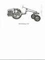
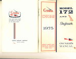
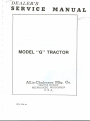
MODEL "G"
TRACTOR-
Allis--Chalmers
Mfg. Co.
TRACTOR DIVISION
d>
-
MILWAUKEE, WISCONSINU. S. A.
.;~
#CU 279 Xl
)
·.
~.
ALLIS-CHALMERS
MANUFACTURING
CO.
Milwaukee, Wisconsin
Allis-Chalmers
Allis-Chalmers
Model "G"
HD19H
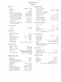
ALLIS-CHALMERS MODEL "G"
Allis-Chalmers Mfg. Co., Milwaukee, Wis.-
1948-1958
1948
Air Cleaner: Donaldson, oil bath.
Battery: Auto-Lite.
Brakes: Two, operated by foot pedals.
Carburetor: Marvel-Schebler, % in.
Clutch: Rockford, single dry plate.
Generator: Delco-Remy.
Governor: Continental, centrifugal.
Ignition: Delco-Remy, distributor and coil.
Lamps: Guide Lamp .
. Oil Filter: Own.
Radiator: Perfex or McCord, fin and tube.
Radiator Cover:
.
Spark Plugs: Auto-Lite AN-7.
Starting: Delco-Remy.
Data: H.P.-Neb. Test No. (not tested).
Number of plows recommended: One,
12-in.
Engine: Continental N-62; 2%x3%, 1800
r.p.m., 4 cylinders, L-head, cast en bloc.
Piston displacement 62 cu. in.
Pulley: 6x4, 1950 r.p.m. and 3070 f.p.m. at
normal engine speed.
Speeds: M.P.H. Forward 1.58, 2.19, 3.46,
6.71 and 2.54 reverse.
"
SERVICE MANUAL FOR THE tv«:>DEL ''0'' TRACTOR
1
The {'ngine for the model "c'· tractor is mounted in the rear of the tractor.
For purposes of identification, the engine will be referred to as crank end.
flywheel end, manifold side and generator side. The No. I cylinder will be
at the c rank end of the engine.
The design of the model "C'· tractor lends itself to a variety of procedure
for following practical repair work. The following general procedure may
be followed in removing major assemblies
from the complete machine.
The complete engine may be removed as a unit. The engine must be removed
to do any repair work on the dutch, throwout bearing. flywheel or oil pump.
-
:.': The engine and clutch housing may be removed as a unit if the differential
is to be removed or the transmission dismantled.
,
Removal of the complete engine assembly or of the clutch housing must be
~a~e if the belt pulley drive gear or engine intermediate gears need servIcIng.
The adjustment of the transmission shaft bearings and removal of the special
low reduction gear may be accomplished if the to rque tube is removed from
tractor.
If the complete transmission and differential is to be repa'ired. the torque
tube, the engine, clutch housing and the two wheel axle aStiemblies must be
removed.
•••
,,'-"'" j
C - I
•
MODEL
"G"
TRACTOR
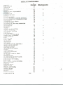
INDEX
G
SECTION
·SUBJI-.CT
AIR CLEANER
A t-.1t-.tF: Tl:'. R
8
SPECIFICATIONS
3
11
BATTF.RY
nf-~l.T PULU-;: Y
('
.
.~.
"" -'~. ~ 40'·;
19
19
lO
. BRAK~:S
BRAKf>PFDAL
AD] USTMENT
CAMSHAr'T
.f:ARBURETOR
CONNF.CTING
ROD
CLUTCH
CI.UTCH
HOUSING
CLUTCH
HOUSING
& ENGINE
REMOVAL
C l.UTe H THROWOUT
BEARING
81 FORK
CRANKSHAFT
CRANKSHAFT
OIL SEALS
CYLINDFR
HEAD
DIAGNOSIS
OF TRACTOR
PROBLEMS
DlFFFRFNTlAL
DlST HIBUTOR
DHAWBAR
fo~NGINF.
F'.NGINI: OILING SYSTEM
1'~NGINr: RE:.MOVAL
I-:l.FCT RICAL SYSTEM
FAN BI-'.LT
FAN ASSEMBLY
FLYWHI-:1-2L & RING GEAR
FRONT
AXLE. &I SPINDLE
FRONT
W HEF:LS
IZ
ZZ
zs
Z6
3
3
3
4
17
Z6
18
3
19
16
31
14
3
9
3
Z4
17
10
13
7
S
5
Z7
36
36
5
FUr.'.L
30
FU~:L FILTER
FUI-:L TANK
GF.AR SHIFT
GF:NF.RATOR
GOVF.~RNOR
GOVERNOR
WEIGHT
ASSEMBLY
HOOD & HOOD SUPPORT
HYDRAULIC
PUMP
IGNITION
SWITCH
INTF.:R MEDIATE
GEARS
LIGHTS
LIGHT SWITCH
LOW GEAR (SPECIAL)
MANIFOLD
OIL SEALS,
FRONT'"
REAR
OIL PUMP
OILING SYSTEM
OIL PRESSURE
RELIEF
VALVE
PISTONS
&.
RINGS
RING GEAR &. FLYWHEEL
RADIATOR
& AXLE
HOUSING
RE:I::L WHEEL
SPF.CIFICA
TIONS
STARTER
STEERING
GEAR
SPARK
PLUGS
SPECIAL
LOW GEAR
TIMING GEAR COVER
TIMING
E.NGINE
TRANSMISSION
VALVES
WIRING DIAGRAM
Supplement
No. 28
30
5
34
11
IS
3
16
7
39
11
Z6
II
10
3Z
36
17
19
Z4
ZI
ZZ
Z7
S
Z8
Il
4
S
3
3S
3Z
15
14
3Z
ZI
10
G-Z
S
4
,..f
SPECIFICAI1Ul""
ENGINF:
F:NGINF.
CRANKSHAFT
Type
C>'linders.
Bore
Stroke
Piston Displacement
},',nginc Speed Full Load
r~ngine Speed High Idle
Fngine Speed Low Idle
Conlpression
Ratio
Prior to (....ng. l3988
I·:ff. On Eng.l3988
Firing Order
Rotation
Conlpression
Pressure
(Starter
Speed)
L-Head
4 cycle
4
2-3/8"
3-1/2"
6l Cu. In.
1800 H.P.M.
2100 R.P.M.
500 R.P.M.
5-3/4
to 1
5-5/b to 1
1-3-4-2
Clockwise
90 to 95 lbs.
Oil 8ath
1/2 pint
Type
Capacity
CAMSHAFT
CONNECTING
Adj.
,0001"
,003"
Adjustable
.OOZ"
.003"
75
&.
,DOh"
to ,007"
to b5 ft. Ib~.
5 to 10 ft. Ibs.
.002" & .020"
BLOCK
Size
Z.376"
.00 1 "
Bottom
1.,3765" - .001"
Piston Clearance
,OOZ"
Rebore at
.010" or mure
Ridge - Remove if replacing
Rings
or bearings
1-1/4"
.003"
to .0045"
.007"
.147" to .149"
.005"
.007"
15 to lO ft. Ibs. torque
CARBURETOR
Idle Needle
1.999 to 2.000
.0015" to .00l"
DISTRIBUTOR
1- 3/4"
&<
Marvel Schebler
Type
Throttle
Flange
Venturi
Float Level
CYLINDER
Bore
Top
AIR CLEANER
Journal
Size
Center
Front
Rear
Clearance
Replace-maximum
Thrust
Plate
F:nd Clearance
Replace at
Thrust
Plate
Capscrews
Main Bearings
Dia. Journal
Clearance
Maxin1um - Replace
Replace
shaft if out of
round or taper
F~nd Thrust
Shims
I'~nd Clearance
Main Nut Torque
Pal Nut Torque
Undersize
Bearings
TSV - 13
Updraft
Gear 8acklash
.0015" to .003"
Maximum
.OOB"
3Zc
Cam Angle
.OZO'
Point Gap
Condensor
,18 to .Z3 Microfarad~
Battery
distributo'
Type
Clockwisl
Drive
3
C rank Pulley Timing Mark Advance
1Z
Advance - Auton1atic
15
Hunning Advance
GOVERNOR
5/8" SAE
7/16"
1/4" from nearest
edge
of float to top of bowl
approx. 1-7/8 turn
open
Zl rol
3/ IE
Z-7/3
500 to ZIOO R,P.J
LUBRICATION
ROD
Length
Squirt Hole
Piston Pin Oil Hole
& Shake Proof
Capscrew
Lockwasher
Side Play
Replace at
Shims
Journal
Size
Bearing Clearance
Maximum- Replace
Undersize
Bearings
Capsc rew Torque
Needle 8earing
Pivot Ball
Spring - free length
Speed Range
5- 3/4"
1/16"
5/3l"
5/16"
.006"
to .010"
.0 14"
None used
1.499 to 1 .500
.0015" to .00l"
.00l"
&<
.004"
.0lO"
lO to l5 ft. Ibs.
G - 3
Press\
Gear t~
Type
Pump
Pressure
Capacity
Filter
Oil
7
(according
to ZO 1
3-1/Z q
own-cotton
wa
SAE lOW to SAE
to load
temperatu
&<
ENGINE
SPECIFICATIONS
OIL PUMP
PISTON
Gt>ar Backlash
.001" to' .002"
fv1axinmnl Gear Backlash
.005"
.004"
Tooth Tip to Body
Gear end clearanCE:
.004"
Drive Shaft Clearance
.002" to .0035"
iI1 bushing
DJ-ive Shil-ft Clearance
,006"
in bushing maximunl
Driven Gear Shdft
_001" loose to ,DOl"
in body
press
Driven Gear Shaft
,0005" to ,0025"
in block
loose
Treated
Oil Pump to block gasket
paper
,007" thick
Oil Pump cover to body
gasket - lead
Capacity
7-1/2 Clt, per min,
Pressure
Minimum
----- 7 Ibs,lvIaxirn_um
lO Ibs,
Spring (relief valve)
pailltt'd greell
Length (free)
1-15/16"
Standard
PISTON
Size Service
Chromium
F:nd Gap
Replace
Releived
SPARK
,DOl"
l/l"
above skirt end
450 each side of pin
True Round
,0035", ,020",
,040"
.040"
2.362" to 2,364"
2.3735" to 2,3750"
2-9/31."
.5433"
,003"
Light
Very light
.0003" loose
used
Expander
used
rings
.0015"
to .0035"
.0045"
when gap inc reases
above
times the bore wear,
Size
Point
PLUGS
,020" &. .040"
is rebored
A.C. 45 or autolite
AN?
14 M.M.
Gap
.025"
VALVES
Intake Tappet Clearance
,01 ZIt cold
Roto Exh. Tappet Clearance
.01 Z" cold
Timing
Marked gear
Inlet Opens
T .D,C.
350 after B,D.C,
Inlet Closes
Exhaust
opens
40° before B.D,C,
Exhaust
closes
T .D.C.
Seat Angle
450
Seat Diameter
57/64"
Maximum
Seat Width
1/16"
Intake Stem to Guide Clearance
.001-8"
Replace
at
.005" Maximum
Exhaust
Stem to Guide Clearance
,0035"
Replace at
.007" Maximum
Pilot Size
5/16"
Guide Length
1-21/32"
Location
25/32" from top of block
to top of guide
Service
Guides
factory
reamed
to size
Valve Springs
free length 1-13/16"
Replace if less than
1-3/4"
2,362" to 2,364"
2,3735" to 2.3750"
2-9/32"
.0035" ,.020",
Expander
,012", plus three
Oversize
Rings
Not to be used until block
at
Plate:!
,007" to ,Oil"
Ring Land Clearance
-----R-eplace
at
PIN
Diameter
Oversizes
furnished
Fit in Piston
Fit in Rod
Replace
Tapered
Indicates
to p
Ventilated
Clearance
Aluminum
Carn Ground
Si ze s
Dinlensions
Top
Skirt
Height
3 pe r pi"ston
Top Compression
not tapered
Second Compression
tape red
Oil Control
Iron
Bosses
releived
F:nd of pin
Tapers
Out
Tar_ers Out
Piston
Sizes
Dimensions
Top
Ski rt
Height
RINGS
Number
used
Type - l- roduction
Compression
(2)
Pit Mark
Oil Control
(I)
PISTON
Cdst
(ContI d.)
to- .5435"
and ,005"
push fit
push fit
or noisy
G-4
CHASSIS SPECIFICATIONS
r
fO
r
1i
BELT PULLEY
GENERAL DIMENSIONS
Optional Equipment
Tires
Location
Left Side
Speed
1950 at 1800 of engine
Ratio Pulley to Engine
1.08 to 1
High Idle
2275 R.P.M.
~ize
6" dia. 4" face
BRAKES
Internal
Tire Pressure
expanding
Diameter
15 lb.
12 lb.
Front
Rear
7"
CLUTCH
Type
Size
Springs
4 :00 x 12
6 x 30
Front
Rear
Wheel Spacing
- free length
Thermo
ELECTRICAL
13"
6 volt 70 ampere hr.
(Delco-Remy)
2 charging
rates
High Rate
approximately
13 amp.
Low Rate
approximately
3 amp.
Starter (De1co-Remy)
6 volt
Drawhar
Belt
Recommended
8:00H.P.
10.5 H.P.
-12"plow
Load
RADIATOR
Type
Operating
Capacity
Pressure
Pressure
- Tubular
7 Ibs.
6-1/2 qt.
TRANSMISSION
FAN
Type
Size
Blades
F an Speed at 1800
engine R.P .M.
Ratio-Crankshaft
to
fan pulley
Suction
ll"dia.
Speeds
4
Low (Special - Optional)
First
Second
Third
Reverse
2900 R.P.M.
1 to 1.616
FRONT AXLE
Lubricant
None
5 degrees
Semi-Reversible
None
FUEL SYSTEM
Fuel Filter
56"
Wheel
POWER
17-3/8"
Battery
Generator
Type feed
Fuel
Tank Capacity
Carburetor
Float Level
1 16"
Height - Top of Steering
EQUIPMENT
Castor
Camber
Steering
Toe In
68"
Length - Overall
Syphon:
CROP CLEARANCE
Under Rear Axle
Under Drawbar
36" to 64"
Wheel Base
COOLING SYSTEM
Type
36" to 64"
Front
Rear
Dry Plate
6-1/2" dia.
1-9/16"
1.6
2.26
3.57
6.91
M.P.H.
M.P.H.
M.P.H.
M.P.H.
1.96 M.P.H.
Capacity
b
qt.
TURNING RADIUS
Nith'Brake
Without Brake
WEIGHT
Gravity
Gasoline only
5 gal.
Updraft
1/4" from nearest
edge of float to top of bowl
Felt & Bowl
G - 5
6-1/2 ft.
E-l/2
ft.
1400 Ibs.
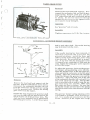
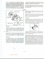
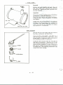
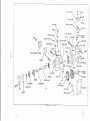
F:':'NGI~~HOOD AND HOODSUPPORT
Removal
-0
portion of the hood support at the crank end
of the engine. Remove the tail light from the
hood support.
The hood and hood suppc·rt IndY be' removed
together if the, capscrcws, attaching the hood
to the radiator are removed and the two
short capscrews, spal..ers,' the oue long capscrew and spacer are removed from the lower
If the"hood alone is to be removed, the bolts
Inust be removed from the hood at the top of
the hood support •
.ELili...,ASSEMBL
Y
Removal
without removing it from the engine. Check
the bearings for wear and roughness. They
should not be rough or worn more than .006'1.
Check the fan belt sheave contact surface for
wear caused by the fan belt. If the wear indicates that the surfaces are curved or that
the belt bottoms in the sheave, the sheave
should be replaced. The fan shaft should be
straight. Check fan blades fa r loose rivets
or cracks.
Loosen the gene rato:l."<'.adrnove it toward
engine in order to rt::nove tension h'orn the
fan belt. Remove the air cleaner and the
instrwnent box from the fan shaft bracket.
Remove the carburetor dir inlet pipe and
bracket from the cylind~r head. Remove
the four nuts attaching JQ~_fanshaft brackets
to the cylinder head.
.. -.-- .
PULLING FAN~·· -~.
__ ...•
To remove the fan h-OlU the shaft, it is necessary to remove the £.'Ulbnicket hon'l the bearings and attach the OTC puller as shovm using
a 1/2" x 2" spacer equipped with a 60° center
between the puller screw and the fan shaft.
lUBE OR SOCKET
TO FIT OVER
SHAfT
INSTALLING FAN SHEAVE
Assembly
Press the front bearing, bearing spacer and
fan sheave on the shaft until the sheave is
flush with the end of the shaft. Place the
front fan shaft bracket on the bearing and
instal: the snap ring. Press the rear bearings
and '::>racketsand fan blade as sembly on the
st.3!.f: until the bearing brackets measure exactly 11-1/4" center to center between the
bearing bracket attaching holes. This method
must be followed in order that the fan sheaves
will line up with the generator and crankshaft
sheaves and to make sure that the bearing
bracket centers will fit the cylinder head
studs of the engine.
The pulley may be removed irom the shc-.fi:
with the same tool. This wo;-k >:naybe done
more satisfactorily if a presE is available"
Inspection
Inspection of th{; fiiIl may b~ acco!'l:l~li~~(>d
G - 7
;."jJ::,'i.' -4;"-;; "H}Q
:~~)_!.~:i-$
.. 5!1j' lr>
'{f--iC
~~ -J
l:::~d
16\,<:u.T~~"
_-, •....;~~
'R~moval.,
. ............---
.•..
.oj;;
, L~16<>ien1;Oi'e ~'hos ec onri'ec t-i 0'0 S"'<at!'e a~'h)~ri'd of
,;:th~~~r·D~-r~.fo·~·'air·· inleCpipe:~and\ i~in'o"vp2:>the
,>:: twfivitufst:Jiltt"iCc
h"ihg:~the1ai'i4 inlet ~lii:pe't:s'upport
io~tn~;:ytirider;·Il~'cid.;' Removeit~e'lW~l%::;ai:lii,~h-
~1::.F;' ~.hp~~.
~tij
~;. qo:!
~ng~~'[arJ!;dE!ane'r'Dodrto~fHe'r'€~f;<Icititl>ra-c ket.
, ~'-
..:,;.:o~,,
-:-2'a:Wfr"~0n._..,
""'''-:'-.~-~~~
----~- "'
".-
,~
...•....•.
,".
.. :;.1
~..;
.:
,>;-
•• , •...•
~.
., ~
-~'
AIR
~.••""..f
..•,
~
._
"".::
~~:.
.
'Check the air inlet pipe, air outl·~t t.ube drain
filter and air cleaner for leaks.
AnY'.1eaks
in ,air cleaner body or between body and carbuh~tor will defeat the puqjosf'ot:the~air
tlEianer':"Check tile drain hol~ at the "lowe'r-end'-of the
:air' inlet pipe ~ahd'rn.ake sure the
ca'rburetor
s tr'~'in'e r'i s~;iIt 'pfac'(' -;-:'If'in i~li'i'ng -p¥ 'loC;s~" it
sh:p~~dhe'repla~ed-.Ba~kwash
Hit; fiiter eI~n'lent,
ma..king :,S,urf.'tha,t all)oreigJ;l 1'1lat(;rial i:s removed from"the' cl('ment and the i'nh~t side of
";,':, '
,
the ai r cleane I' bod}'.:
QUT1ET TUBE DRAIN
';'
,
,
; .~~s~'.~
..' -.;~;1;\:$..~
Removal.
RADIATOR
... '.-~.
the radiator core. l('h~r-d'::d~ alkaline water
has been used in the cooling :-Systme, check the
inside of the radiator and cylinder block for an
accwnulation of scale deposit., Check the hose
connections and hose for deteril'r'ation
or collapsing. The spring loaded pressure
cap retains approximately
7 lbs. of pressure
in the
cooling system and raises the boiling point
to approximately 2300 Fahrenheit. The pressure
cap also incorporates
a vacuwn valve which is
set at 1-1/2 ounces to relieve the system of
vacuum when it is cooling off. When draining
the cooling system, it is best to loosen the
radiator
cap so the s}'stem will not become
air-bound,
which rnight prevent dr-dining.
CA UTION: Do not remove the radiator
cap
if the engine is overheated.
Remo\'e cap \\iter
engine has cooled.
"
..
--.~,-~.~
::
, ,..--:
Removt' fue 1 tdnk and fender's as an assembly.
Rernove the engin~ hood and disconnect
the
two brake rod return springs from the lowe r
side of radiator.
Drain the radiator and remove the uppf'r and lower hose from radiator
inlet and outlet.
Remove the two capsc rews
attachillg the radiator to the clutch housing.
Inspection
The cooling system is of the thermo-syphon
type and to operate
must have the cooling
solution maintained
above the lower edge of
radiator inlet tube. The cooling solution temperature will vary with the prevailing weather
temperature
and will be hottest on the days
when the outside tempe rature is hottest. This
system is automatic and the speed of circulation
varies with the difference between temperature
of the radiator
and the water jacket of the
engine. The engine will operate at a temperature
even in the coldest weather, which tends .to prevent the formation of condensation in the crank ••
case. 1£the engine should overheat, check the
fan belt for slippage.
Check the radiator for
leaks and accumulation of foreign material in
G-8
Assembly
Install the radiator on the tractor using a st:aling compound at the hose connections to pr('vent
leaks. Due to the higher operating temperature
of the thern1o-syphon system, it is not advisable
to use alcohol as an anti-freeze. F,thylene-Clycol
or some similar solution should be used as an
anti-f ree ze.
DRAWBAR
Removal
nut from the drawbar pivot pin.
Remove the four capscrews attaching the
drawbar guide to the cylinder block anti remove the guide. Remove the cotter pin and
For engine removal, remove drawbar ·guide
and swing drawbar to one side.
~.
G-9
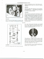
EU':CTRICAL
SYSTEM
~,"--.j
...•
RED
TR.
CUTOUT
RELAY
HEAD LIGHT
CONNECTOR
TAIL
LIGHT
-
}
WIRING DIAGRA
III - Discharge side of anlmeter to cutout.
- Resistor
to generator field terminal.
1/3 - Ignition switch to coil to primary distributor lead.
#4 - Light switch to headlight & tail light.
H5
- Change side of ammeter
to starter .•
1/6 - Generator armature terminal to cutout
relay.
#7 - Discharge side of ammeter to fuse.
#8 - Discharge side of ammeter to ignition
switch.
HZ
When any service is to be performed on the
electricAl ~ystem. the battE'ry ground strap
should be removed. Removal of the battery
ground strap will prevent shorting and damage
to Ammeter pr AOy pt the relative parts of
the e'ptire elettric;al
system.
LIGHT SWITCH
The light switch is n'lounted on the instrument
panel which is located under the engine hood
and is attached to the front fan bracket. The
light sw-:'::h incorporates the generator control, which is of the two step system, having
a high and low charging rate. The fuse for
the lighting system is also mounted on the
light switch. A fuse of either a 10 or 15 amp.
capacity can be used. The operation of the
light switch isas follows: When the switch
is all the way in, the lights are off and the
generator charge rate is at the low P?sition.
With the light switch pulled out to the fi nt
stop the lights are on and the charging rate
is in the high position. With the light switch
pulled all of the way out, the lights are off and
the charging rate of the generator is in the
maximum position.
This manuell control of
the charging rate is accomplished by a resistance unit on the outside of the light switch
G-IO
r
!-n
which is cut into or out of the circuit and
limits the arnoWlt of electrical current allowed
to pass ttnough the field coils of the genera:
tor. The generator charging rate is approximately 3 amperes in low position and 13 amperes in high position.
IGNITION SWITC H
The ignition switch is also mounted on the
instrument panel and is used to complete the
ignition circuit.
AMMETER
The ammeter is mounted on the instrument
panel and indicat~s the rate of generator
charge or battery discharge to the electrical
system.
I.
kept free of grease and dirt accumuiatibn
All grommets should be in place and ih good
condition.
Assembly
Inspection
See the wiring diagram for the connections
which must be made to complete the wiring
system.
Keep all connections clean, bright
and tight.
Inspect all wires and make sure they are free
from cracks, broken wires or terminals and
free from deterioration.
They should also be
HEADLIGHT AND TAIL LIGHT
Removal
Both lights use single contact 6 - 8 volt bulbs.
The headlight is 32 cclndle power and the tailThe headlight is mounted on the front frame
light is 15 candle power. With the single conof the tractor and may be removed if the
tact bulbs, it is necessary
to have all the
headlight wi re is disconnected
at the front
lamps and tractor parts which are used to
frame. If the wire is to be removed from the
complete the circuit, clean, bright and tight.
Dull reflectors
cause inefficient
lighting.
torque tube, it is advisable to place an extension on the wire that may be left in torque
The reflectors should be replaced if dull or
tube when the light wire is drawn out. With
polished by the use of lamp black or silver.
this extra extension it is possible to replace
polish. In polishing the reflector, use a soft
cloth that will not scratch the reflector.
Althe head light wire without any difficulty.
ways use a new gasket between the lamp and
The tail light is mounted on the hood support
reflector to prevent any moisture from acand the wire is connected directly to the light
cumulating on the reflector surface.
swikh.
GENERATOR
Removal
Manual for details on the generator.
The
generator
should be repaired
only by an
authoriz'ed
service
station.
Remove the capscrew from the generator
brace and the wires from the field terminal
and ammeter or cutout terminals of the generator. Remove the two bolts from the lower
pivot point or the two nuts attaching the generator mOWlting bracket to the cylinder block.
The generator is driven by the fan belt. To
adjust tension, loosen clanlp screw and move
generator
away from cylinder block. See
"fan belt".
Inspection
Refer to the general
section
of the Service
G-ll
STARTER
.;'
Removal
"
lnspectio
Ch(~ck the battery terminals for cleanliness
and tightness. All connections must be clean
:c·_:.:' and tight.
lri~cold \,veatner ifthe Marte'i'does nof enga'ge
the flywheelprornptly ,''the :starter drive screw
threads should be washed out with kerosene.
,Do not lubricate the starter drive threads but
the -.'.kerosene ~..
as .-. the only lubricant. .
:leave
~
n
.
.
See the general section of the service mimual
for details on the starter. The starter should
be repaired only by an authorized service
station.
When r~installirig battery cable, place it under
radiator and not around side of radiator.
-
CARBURETOR
The carburetor is a tv1arvel-Schebler TSV-13.
sizes are not marked on the jets of
this carburetor and reference must be made
to part numbers to be sure the correct parts
are obtained.
The']el
SHAFT
ReITX>val
.-e
0-
=
Remove the carburetor
air inlet pipe, the
choke rod and the fuel line. Disconnect the
carburetor link rod to the 'governor. Remove
the two capscrews attaching the carburetor
to the intake manifold.
VALVE
Inspection
CHOKl
\
\
SHAFT
Inspect the choke shaft and throttle shaft for
wear in the body. Any wear at these points
will allow the entrance of dirt to the engine
and cause uneven operation at low speeds.
Check the float and the float valve {or leakage. Check filter in intake pipe for loose
felt through which dirt might enter.
ROAT
,
Assembly':
The float level should be set with the float
1/4" from the top edge of the bowl or 1/4"
between the bowl gasket and the nearest edge
of the float. The idle needle is set approximately 1-7/8 turns open. The float may be
set by bending very near the float axis, being
sure not to cause the float to stri'ke the edges
of the bowl.
'.
With the engine heated to normal operating
temperature, the idl~ stop screws should be
adjusted to permit the engine to operate at
approximately
500 r .p.m. at low idle.
T
G -
lZ
FAN BELT
Removal
Loosen the generator brace and move the
generator closer to the cylinder block. Remove the upper right capscrew and spacer
attaching the hood support to the cylinder
block.
I
i
Inspection
Check the belt and the condition of the sheaves.
The sheave side should be fiat and smooth
and the belt should not bottom in the sheave.
If the belt is grease-soaked, deteriorated or
broken, it should be replaced.
AssemblY.,
Check the fan belt tension opposite the generator pulley on the straight side of the belt.
The belt should move in or out approximately
one-half inch from the straight line. Insufficient tension causes belt l';lippage or
excessive tension places an overload on the
front fan shaft bearing or the generator bearings.
G-13
DISTRIBUTOR
••..• -.--
..-
,..
,.::..
~.: '.
-:
'.
-.-
,,
.-t---
. .~~.
.....•...
---
..
',~!.~;~,
DISTRIBUTOR
CAP
;;~~~;~J
:,',
'
..
.,
j
,/
.__rP,'
"
t,: .''.., ~.'.~ ~
CONDENSOR
- -'-- ---' -_.
Removal
Remove th~ spark plug wires and coil wire
wire from1:he top of the distributor. Disconnect the; primary coil wire from the coil
to the side' of the distributor.
Loosen the
clamp screw at the base of the distributor
and pull distributor up out of engine.
Inspection
Check the breaker points for pitting or wear.
Assembly-'
To set the breaker point gap the distributor
rotor and the dust shield must be removed
from the distributor. Turn the distributor
until the points are separated to their widest
position.
Loosen the lock screw on the fixed point and
turn the cam screw until the points are separated .020". Tighten lock screw and recheck
point adjustment.
To time the engine, turn the engine \mill No.1
cylinder is at top dead center on its compression stroke and the timing mark on the
fan pulley is located in the center of the timing inspection opening directly below crank
. ,fi:.~'Q,:"
,
,
DUST
SHIELD'
, ,
,
,;,'
ROTOR
support in the hood support. Hold the distributor with the coil wire terminal pointing
toward # 1 spark plug, and the rotor pointing
towards the clip farthest from terminal. Enter
the distributor into the engine block in this
position. As the distributor enters the block
and the gears mesh, the rotor will turn
slightly in a counter clockwise direction.
Clamp the distributor in place partially and
turn the distributor body in a counter clockwise direction until the points just start to
open. Clamp the distributor body securely
in this position. This will place vent in dust
shield downfor proper drainage. Place No. I
spark plug wire directly above the rotor and
then proceed around the distributor in a clockwise direction placing 3,4, l spark plug wires.
Place the high tension coil wire in the center
outlet of the distributor cap. Attach the battery lead wire from the coil terminal to the
terminal on the side of the distributor body.
Use a good grade of rubber cement or shellac
on the rubber nipples on the distributor to
spark plug wires and high tension coil lead.
The distributor is a Delco-Remy model
1111708 and all repair parts and service
should be obtained from United Motors
Service.
#
G - 14
TIMING GEAR COVER
r
rO
r
Removal
Remove the hood and hood support. Disconnect the carburetor link rod and the governor spring. Remove crank jaw. Use twc
3/8" caps crews and pull crankshaft pulley
as shown. Do not run cnpscrew throug};
against die cast cover or pry against cover
as it may be easily damaged.
r
Inspection
See "governor" and oil seals.
Assembly-
--
Tighten capscrews
"---
to 15 ft. lbs. torque.
--~.
PULLING CRANKSHAFT PULLEY---GOVERNOR
&
GOVERNOR WEIGHT ASSEMBLY
ball is used under shaft. The needle bearing
may be driven from the cover.
Assembly
If the needle bearing has been removed, it
should be replaced with a new part anc
pressed into place. Install the lever and
shaft assembly in the timing gear cover using
a new dust seal. Be sure pivot ball is in position. At any time when the timing gear cover
is reznoved a new crankshaft oil seal must be
used. Tighten the timing gear cover capscre'l.\
to 15 ft. lbs. torque.
Removal
Remove the hood and hood support and the
fan belt. Pull the crankshaft fan drive sheave.
Disconnect the carburetor throttle link rod
from the carburetor and the governor spring
from the governor arm. Remove the timing
gear cover from the engine.
Reznove the snap ring from the governor shaft
and turn the shaft until the tapered groove pin
can be driven out of the governor arm. The
shaft and lever assembly can be pulled from
the timing gear cover. A 3/16" thrust pivot
To adjust the governor, back out the governor bumper spring adjusting screw entirely.
Place the throttle lever in the full speed position and hold the carburetor in the full speed
position. Adjust the carburetor link rod until
it just fits between the governor arm and the
carburetor. Adjust the ball joint at the end
of the carburetor throttle link rod until it is
free of all slack but not tight. The throttle
rod is provided with a stop to keep the engine from being over speeded. Make sure
this cotter pin stop is in place. Be sure that
the throttle rod has not been bent at the spring
end which would cause interference with the
spring.
The governor bumper spring adjusting screw
is provided to eliminate surge from gove~nor. It is usually not necessary to use this
screw - however, if the engine does surge
G - 15
the screw should be turned in slowly until
surging is overcome. If the surge screw is
turned in too deeply, it will increase the
r.p.IX1oat which governor action takes place.
This increase would be from low idle to a
maximum of 700 r.p.m.
Governor Weight Assembly
Removal
Remove the timing gear cover and the governor thrust cup assembly. Remove the governor spider and weight assembly from the
timing gear.
Inspe-ction
The
governor
thrust .OOZto
cult assembly
fits the
camshaft
with from
.004" clearance.
It should be replaced if this·clearance -exceeds .OOS"or if-the cup is worn at the weight
riser contact surlace. Check the vent hole
in the camshaft behind the thrust cup shaft
and be sure it is clean and free of any foreign
material •. If this hole becomes plugged, the
governor wl1l be inoperative due to the vacuum created behind the thrust cup shaft. Check
the governor weight for wear on the riser
and any wear at the hinge points. The assembly should be replaced if the hinge pins are
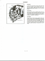
worn more than .006" CYLINDER HEAD
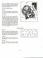
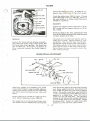
Removal
(Qr15 (Qt-3
Remove the hood and hood support, carburetor air inlettube, air cleaner, instrument
panel, spark plug wire grommet holder !Uld
fan assembly. Drain the radiator and remove
the upper hose. Remove the balance of the
studs and nuts from the cylinder head.
~617
©-,o
©rl
(Q)
©r18
Clean the carbon from the cylinder head and
check the head for leaks or cracks and scale
accUD1Ulation.
AssemblyInstall the head using a new gasket. Tighten
the stud to 55' pounds torsion following the
chart.
G - 16
0
©-4
<Q)-13
2~
i:f7
1,©
©,,8 20 0
19A])
@@
12 (Q(6
~
(Q)
9
0
14-©)
OIL SUMP
Removal
oughly and inspect the screen for broken
mesh
Remove the drawbar guide and swing the
drawbar to one side. Drain the oil sump
and remove the small cover over the lower
portion of the clutch housing. Remove the
capscrews attaching the oil sump to the
cylinder block.
Assembly.
Use a sealer on the one side of the gasket
surface only. Tighten the end capscrews
which enter the die cast timing gear cover
and rear oil seals to 15 foot pounds torque.
To overtighten may strip threads from die
casting. Refill sump with fresh oil.
Inspe ction
Clean the oil sump and pump screen thor-
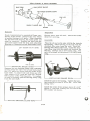
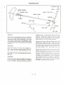
ENGINE REMOVAL
hoses. Remove the drawbar guide. Remove
the starter and choke rods and the battery
cable at the starter - also disconnect the
headlight wire. The engine may be supported
from the fan shaft bearings, however, do not
hook in such manner as to pull bear ing
brackets closer together or to place a strain
on shaft. It is best to use a solid bar as
shown or a spreader must be placed between
the chain ends close to the fan shaft bearing
bracket. Disconnect the fuel line, remove
throttle rod, remove the bolts from the clutch
housing and swing engine away from tractor.
BALANCE POINT FOR CLUTCH
HOUSING
AND ENGINE
Clutch Housing and Engine Removal
The small housing and engine may be removed as a unit by following the engine removal procedure and removing the clutch
pedal rod from the throwout bearing fo rk
and unhooking the brake return springs at
the bottom of the radiator support. The
same lift arrangement can be used excepting
the balance point for the engine and clutch
housing is about 4" closer to the flywheel
end of the engine. After attaching the engine
to the chain hoist, remove the capscrews
attaching the clutch housing to the transmission housing.
".
'\\ .. '
. J;:
REMOVING ENGINE
The complete engine may be removed as a
unit as follows: Drain the cooling system
and the oil sump and shut off the fuel supply.
Remove the hood, hood support and radiator
MANIFOLD
Removal
Assembly'
Remove the carburetor air inlet tube. Disconnect the fuel line and governor link rod
and governor spring. Remove the throttle
rod guide. Remove the nuts attaching the
manifold to the cylinder block.
Install manifold and tighten nuts to 20 to 25
ft. Ibs. torque.
Install the pin in the throttle rod ahead of the
throttle rod guide..This pin prevents the engine
from being overspeeded.
l~§J~ection
The intake manifold vacuum is 18 to 19 inches
at low idle when the engine is in good mechanical condition and properly adjusted.
Check the manifold for carbon accumulation.
A partially plugged manifold will cause rapid
loss of power. Check the manifold for leaks
or cracks. Always use new gaskets.
G-
17
CRANKSHAFT
. ,
.,:
;::1
••
PUlLEY
SEAL
INSERT
LOWER
~-.) .'"..~
PULLING CRANKSHAFT GEAR
size the undersize bearings should be used
for service. Check the end of the crankshaft
at point contacted by oil seal and the crankshaft pulley at point contacted by oil seal. If
worn excessively at either place, they should
be replaced. The end clearance of the shaft
should be maintained within .003" to .007".
The clearance itmst be checked with all parts
in place including the crank jaw which is used
to retain the thrust washers in position. It
is best to check end clearance before disassembly. It will not be necessary to dismantle the engine to adjust end clearance
until such time as it is increased to .011".
However, if the engine is down for any other
reason the end clearance should be adjusted
to the specified limit.
Removal
Assembly'
Remove the engine from the tractor. Remove the clutch and flywheel. Remove the
crankshaft fan pulley and the timing gea r
cover. The crankshaft pulley may be re-
The main bearing inserts may be installed
without removing crankshaft if a small pin
is inserted in the crankshaft oil hole and the
upper shell rotated out of place. The main
bearing shell has an oil hole in the upper half
and is solid on the lower half. The spurs on
the shells to prevent turning in the block are
diametrically
opposite.
maintobearin~
clearance should
be fromThe
.0015"
.OOZ'aoil
nd
should be adjusted if it reaches .004"or more.
Do not file main bearing caps or inserts.
Tighten the main bearing nuts to 70 to 80 foot
pounds. Tighten pal nuts to 10 foot lbs.
puller
moved with
by using
a 1"two
x l-l/Z"
capscrews
spacerand
with
the aOTC
600
center. Do not pry on die cast gear cover
or turn capscrews in against cover. ReInOve
the oil sump and the main bearing cap. Remove the connectinH rod bearing caps.
Check the crankshaft journals for wear,
scoring and out-of-round. The shaft should
be replaced if worn or out-of-round more
than .003". .OOZ"undersize bearing shells
are provided for service. The bearings do
not use shiIns, and if the shaft is worn under-
Both thrust washers should be placed on the
shaft with the bevel on the inside diameter
towards the first crank throw of the shaft.
The steel thrust plate goes against the bronze
thrust washer with the large surface towards
G - 18
T
T
the bronze washer •• 002" and .008" shims
are used between the steel thrust washer and
the shoulder on the crankshaft
to adjust the
end clearance.
Either the shaft tnust be removed to adjust end play or a special puller
used to remove the crankshaft
timing gear.
When installing
the crankshaft,
the crankshaft
gear must be meshed with the camshaft gear
according
to the marks.
There is one mark
on the c rank gear and two on the ~am gear.
Place the single mark between the double mark.
The main bearing caps are marked No.1 and'
No.2 and the block correspondingly
and these
marks should face the camshaft side of engine.
CRANKSHAFT OIL SEALS
!
The crankshaft
seals are Neoprene seals,
spring loaded.
They must be installed with
the lips toward the oil supply in the oil sump.
The seals must be replaced each time the crankshaft is removed or the timing gear cover
removed. The front seal has a felt seal installed
on the outside of the Neoprene seal. Shellac the
felt seal to the face of the Neoprene seal. When
replacing seals, be careful not to damage the die
cast retainer.
r
If difficulty is encoWltered with the seals seeping
or leaking oil, check the surface of the crankshaft at the flywheel end contacted by the oil
seal and the surface of the crankshaft fan pulley
contacted by the front seal. If these diameters
are worn too small for the seal to make a firm
contact, the parts should be replaced.
Be sure
the regular oil sump capscrews are used in the
center hole of the rear oil seal retainer.
If an
extra long capscrew is used on this position,
it will force the seal away fron1 the retainer.
OIL PUMP
Removal
Remove the engine from the tractor and remove
the clutch and flywheel. The pump is mounted
at the rear of the engine bloc~ and is driven by
the camshaft.
The capsc rews that attach the
oil pump to the cylinder block also hold the
pump assembly
together.
Inspec tion
Check the pump for gear back lash, which should
not be more than .005". The clearance between
the tips of the teeth and the pump body should
not exceed .004". The clearance between the
gear and cover for the side clearance of gears
should not exceed .004". The minimum permissable oil pressure is 7 pOWlds per sq. inch.
Later pumps have short idler shaft and no hold
in plate.
body and the cover and the treated paper gasket
is placed between the pump <lndcylinder block.
If oil pump strikes clutch housing it will cause
gears to cut into pump body, shearing drive pin.
Assembly.
When repai ring the pump, the oil sc reen and
suction line to the pump should be checked and
must be clear and free of leaks. The oil gallery
in the cylinder block must be clean to 15 foot
Ibs. Use a sealer on paper gasket between body
and block.
A .007" thick lead gasket is placed between the
The desired
The drive shaft clearance
should not exc\~ed
.006". The desired clearance is from .002' to
.003" •
G-19
oil pressure
is 15 to 20 pounds
per square inch and can be obtained by ad-"_"",;
justmentof theoi! press~e reliefvalve-. '00- _ ._
not atter.1pt to adjust low oil pressure·by-use,
':'
.
<
of the pressurereUef
valve until all other
sources 'of low oU-pressure -are, investigated.
-
,
: ~...>
',.
~
:~
".:.::1'.
,"
r:·:
.;
CAMSHAFT!.
:.:.
~t·"'1;
..-
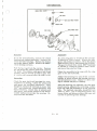
the governor spider assembly and pull the
camshaft timing 'gear • 'Remove the cam'
shaft thrust plafe and pull the camshaft from
the.engine. '
The cam followers or tappets may be removed from the valve compartment if the
adjUsting screws are removed.
Inspection
The maximum clearance between the camshaft journal and the cylinder block should
not be more than .007". Check the camshaft
vent opening into the governor thrust cap
- '-" - ·"shaft. H this hole is plugged, it will be impossible to obtain good governor action.
Removal
Remove the hood and hood support. Drain
the oil and remove the oil sump. Remove
the cylinder head and the valves. Remove
the crankshaft fan drive pulley and the timlng
gear cover. Remove the distributor. Remove
Check the openingbetween the center of the
front cam journal and the oil hole leading to
the thrust plate. Check the shaft journals,
cam lobes andcamfollower faces for wear or
scoring. H scored, they shouid be replaced.
The back lash of the timing gear will not
cause the engine to become inoperative,
however, as clearance increases noise will
also increase. Noise usually becomes objectionable as the back lash clearance approaches .020".
The end play of the camshaft should be approximately .005". H this clearance exceeds
.007", a new thrust plate assembly should be
used.
Assembly'
PULLING CAMSHAFT GEAR
Whenthe camshaft is replaced or reinstalled,
the valves must be timed. There is a single
mark on the crankshaft gear and a double
mark on the camshaft gear. The single mark
must be placed between the double mark.
G - 20
r
OIL PRESSURE RELIEF VALVE
I
It may be removed by use of a heavy duty screw
driver. Beneaththe plug is the spring and plunger
asserrbly.
Inspection
Check the relief valve spring for its free length,
which should be 2". The spring is painted red
for identification. A neoprene seal is used on
the plug to prevent leakage.
Assembly
Removal
T
The oil pressure relief valve is located on the
flange of the cylinder block near the oil pump.
The oil pressure relief valve should not be used
to increase the pressure of the system until
all other sources of low oil pressure are investigated. The minimum allowable oil pressure
7 pounds. The desired operating pressure 15
to 20 pounds. The gauge is not calibrated in
pounds, but the center of the indicator needle
travel on the gauge face is approximately 15
pounds. The pressure may be regulated by
placing washers between the spring and the
retaining plug.
VALVES
der head. Remove the distributor, the throttle
rod and the carburetor and the valve cover.
Use a valve lifter or spring compressor to
remove the keepers from the valve stems. The
valves may then be lifted out.
INTAKE VALVE
rHAUSTVAa;~
_~KEEPERS
-_
r-
[r'GUID'-
~ 1N
INTAKE
~SPRING
I
RETAINER, "'10 I
EXHAUST
I
~RETAINER
lJ
fL-:OJusnNG1
SCREW /~
V-T~
Removal
~lOCK~.
ROTO VALVE
The engine is equipped with roto caps on the
exhaust valves. These caps provide a means
of relieving the spring pressure from the valve
when it is in the open position, allowing the
valve to rotate on its seat. These caps increase
valve life. Set exhaust valve clearance to .010"
cold when equipped with roto caps.
The valve guides are removable and can be
driven from the cylinder block if necessary.
Always use a suitable driver.
Drain the cooling system and remove the cylin-
G-21
in order. ·to.pre_v~nt distortion of the guide
driven from the cylinder block.is necessary.
Always use a suitable driver.
~
Ins~ction
.' .', is collapsedrit;wilLbe
necessary. to.rearn.,._ .•...
,."':,'
the
~~_~ZJ~te"r...:;,t~~
..guides
are
in
pl~,~"':l;>~.;.:
•
a 45 cutt~r.!to·~eseat the. valve seat~·,·,Us~,
The valve face and seat angles are 450• The
seat width should be approximately 3/64" and..
not over 1/16". The intake valve stem clearance is ~0018"and should be replaced if the
combined clearance between the stem and
guide exceeds ~005"• The ·exhaust valve stem
clearance in the guide is .0035" and the maximum allowable clearance is .007" between
the stem and the guide. Replace that part
which is worn most or both, if necessary.
..
-bore ·while··ariVi:iig~in place.
If the guide bore
·~:~~~I~'~!t:~f;1i;a1
grmding':(:.ompo,und.. yalve clearance ls'set{''';
to .012'~.WiWpi'eengine cold. Exhaw;i valves; .
with :;t"oto:~
cj(ps are;set-.Ol 2""With:engine.~old.·::··
Thesevalves:'inust be.:f.ree to rotate. The'
clearance,'1>~~een cap ~dstemis
.004" to
.006". ':C(
.. .
.
...-.....
I.",~~.-·
::.'~~~.
;.;:
Service guides are reamed and ready for use
and are all the same size. The difference in
clearance between intake and exhaust valves
is taken care of on the valve stem. A 5/16"
diameter pilot.is required for checking the
guides. These pilots may be secUred in.OOl"
.002", .003" oversizes. The valve spring is
cadmium plated and 1-13/16" long. The spring
should be replaced if it is less than 1-3/4"
long.
Install vaA~e spring with closed end or 3
closed COlIs end towards cylinder block.
~
Assemblx~
To set the tappets it is necessary to have a
The valve guide is 1-21/32" long and should
thin jawed 7/8" tappet wrench that will work
be driven into the cylinder block until it is
between the adjacent tappets without interexactly 25/32" from the top face of the block
ference, also thin tappet wrenches in 9/16"
to the top of the guide. Use a special driver
and 3/4" sizes.
CONNECTING RODS. PISTONS & RINGS
Removal
Drain and remove the oil sump. Remove the
connecting rod caps and lift the rods from
the crankshaft. Remove the connecting rod
and piston assembly from the bottom of the
eng~e opposite the camshaft side. The
piston pin is a full floating type and may be
removed after the retaining snap rings are
removed, if it is desired to separate the
pistons from the connecting rods.
Inspection
The piston for 'the Model "G" is finished to
a true radius.
However, it does have a
tapered relief over the end of the piston pin
bosses. This relief varies from .002" to
.007" deep, tapering out approximately 1/2"
above the lower skirt end and 450 at each
side of the pin center line. This appears as
a discolored triangular shape after the engine has been in use a short time.
The skirt diameter is 2.375" approximately.
The skirt diameter and piston weight will be
G - 22
u
marked
on the piston top.
T he a lWTIinurn piston-";;~d-N62-'jil7:i '~d;b~ve
T'he camp'r'es'sio'n 'rings ·6f'the tractor s are
tapered and have a small pit mark: on tht' top
is cam ground.
When fitting ca'ffi ground
side. The standard size service ring set will
pistons use; a .OOZ" feeler strip I/Z" wide
plated top compression
between the cam or tight side of cylinder .~~ll •.. .. consist,of·"'.chromium
~'ring
ttiat
~ij~;nl?t
be
tapered
and tilt' spcond
With feeler strip in place at tightesU)oint,:.:~ou· .
should be able
to
move
the
pi!iton~ya
slight.
.'~ompre·ssioh
·ring.
which
will
be
tapered.
All
.
. ,~ '. .
'..
. .
push with thumb. If recommerid~<iClearance,
,'tapered rings will have a pit mark on the top
can not be obtained hone or 'rebore for next
·"side. The. lower' compression
ring will Ill'
fitted with~n.exp;mder.
The oil control ring
larger size: piston. Minimu~' clea;ance_is ..
.will also be._supplied with an expander .
•001" to .OOZ" between. piston arid.cylinder.
,."~_)3~-··~·::~
. .: .. :"-.:
wall.
'
..
,.
'.Fit ~'~h ritlg' in the lower part of the cylinder
The pistons are serviced hi standard size
block bor~<w~ere piston ring travel stops or
.0035", .OZO"and '.040" over!iiz~s ~o·pr'o,,:ide
where the wear is the least. Try each ring in
pistons when reboring or honingls necessary.':':"
the groove un·the piston in which it will 1.)('
'\
-
The piston pin {S:fitted~ith~;W:~
light push
installed to ,;Jttt surethat
it is free ..
fit in the connecting rod and'~ ,'light push fit
The lowest pb:rtion of the c ylinde I' bore 1S
in the piston. They -should be replaced ,when
chamfered 450 to permit installation
of the
.0003" loose or wnennoisy •..j;•.•...
·-:~-:;f'ft:,.~-' '-' _·:·~,-:--rings·'without
the need of a ring cr,rnpressor.
, '.,:<'
'.
Pistons and rods must be installed from the
The piston pin is supplied in' .003'~..,.nd ~00511",
.bottom and on the side of the crankshaft
0:ver~izes for repairs.
~.l1e st~:rld.ar;d pin
opposite the camshaft.
S1ze 1S .5435. The production cyhnder block
.
is 'machined slightly tapered, being .0005"
When fitting standard or oversize piston pins
smaller at the top than at the bottom. The,
use a spiral fluted expanding reamer or a
bo)-e size is Z.377". The piston is fit.~itli-<'·
hone. The bushing in the connecting rod is
ap:proximately .OOZ"clearance.
The maxi--·.'·"
very thin and great care must be exercised
mum allowable cylinder .wear is approxiwhen reaming. A very light cut must be used
mately .010".
at all times. Be sure the oil hole in the bush,-.
ing is in line with the oil holp. in the top of
The production
ring gap is f"om .007" to
the connecting rod. Clean the oil hole dfter
.01Z".· The ring side clearance in the piston
reaming.
The' pin fits in the piston with a
ring groove is.0015"
to .0035". Standard
line to line fit and in the connecting rod with
rings may be used for service untilreboring
a .0003" loose fit. A good method of peterminis necessary - then .0lO" or .040" oversizes
ing the type of fit is to use a light push fit in.
are available and the engine should be rethe piston and a very light push fit in the
bored to these standard sizes.
The piston
connecting
rod.
rings should be replaced if the side clearance
exceeds .0045" or the end clearance exceeds
The connecting rod as used in production is
.050"; The cylinder wall should be refinished
marked both on the rod dnd the cap on the
if the standard ring, when new, has .046" or
camshaft side. 1£the standard bearing does
more'clearance.
'.
.
not give the correct clearance on the crankshaft, .OOZ"undersize bearings are available.
The connecting rod has removable bearing
The desired clearance on the connecting rod
inserts
which should be replaced
if the
bearing is .0015" to .OOZ". The spur on the
clearance
exceeds .004". The crankshaft
bearing insert which prevents it from turnshould be replaced if out of round more than
ing in the rod is on oppos ite side s of the
.003". The side' play of the connecting rod is
crankshaft
when the rod is correctly
as-.
from .006" to .010" and should be replaced if
sembled. The oil spray hole in large end of
it exceeds .014".
connecting rod should face the camshaft side.
Tighten the connecting
rod capsc rews to
The bearings are not provided with shims.
Do not file the
ZO to l5 foot Ibs. torque.
The rod or cap should never be filed to obtain
connecting rod, cap or insert to obtain bearing
bearing adjustment.
fit.
.I
i
G-l3
ENGINE-OILING SYSTEM
,l'
0-
The Model lti" engine use. regular srade
lubricating oil of the followinS specifications:
The oil is drawn from the oil sump through
the intake screen and pipe to the oil pump
which is mounted at the rear of the camshaft
and is driven at camshaft speed. The oil
from the pump is forced under pressure into
the oil gallery which is located in the cylinder block between the camshaft and the
crankshaft. The oil pressure relief valve
. is located at the rear end of this gallery.
The oil pressure relief valve prevents excessive pressure from beins developed in
the o"Uing system. Drilled passages are
provided to lead the oil from the oil gallery
to the front main bearing and the rear main
bearins, and the front camshaft bearing. The
drilled passage to the front camshaft is
smaller than those to the crankshaft. The
rear camshaft bearing receives its oil from
seepage from oil pump. The differences in
sizes of the drilled passages assures an
adequate supply of oil to the main bearings.
The center camshaft bearins, cam followers
. or tappets are lubricated from spray. Two
port holes are provided into the valve chamber and the valve springs llnd sterns are lubricated from spray entering this compartment through these two port holes. The front
cam journal has a sroove cut around it s
outside circumference and a hole drilled
from this groove to the front s ide of the
For heavyduty servic~ above 3~F use SAE 30For normal duty operation above 3ZoF use
SAE
ZOo
For tempe ratures between OOFand 3ZoF
use SAE ZOo
Below OOFuse SAE lOW.
Heavy duty operation is any operation in
whicn the engin.e is called upon to produce
half or more of its rated horsepower. Nonna!
duty operation is interpreted as an operation
in which the ensine is called upon to produce
an average of less than half of its rated
horsepower.
New or reconditioned engines should use
SAE ZOoil for the first fifty hours of tJperation and shouldbe operated on light te: :lIediwn
loads if possible.
The oil sump capacity is 3-I/Z quarv!J with
oil filter. For oil changes when the filter
is not changed, 3 quart. will fill the sump
to the required level. The oil filter should
be replaced at least each ZOOhours of operation.
G-Z4
0-
.•...
journal. This hole lines up with the two notches
cut in the camshaft thrust plate allowing two
spurts of oil from each revolution to reach the
thrust plate, the timing gear and'the.governor
mechanism.'· Oil fr·om the front main bearing is
fed through the -drilled crankshaft to No. 1 connecting rod jo_urnal and from No. lthrough
another drilled passage to No.2 connecting
rod journal. Oil from the rear main bearing
is fed to No.4 connecting rod through a drilled
passage and through a second drilled passage
from No.4 to No.3 connecting rod.
Each connecting rod has a small squirt hole on
the upper camshaft side of the large end which
is used to increase the spray on the inside of
the crankcase.
CLUTCH
Check the face of the flywheel and the face of the
pressure plate for flatness. These parts should
no.t be warped.
Check the release lever for wear at the hinge
pins and wear at the throwout bearing contact
surface. Also check the adjusting screw and
pivot or fulcrum points for wear.
-
Assembly
Assemble the plate to the flywheel with the long
hub of the plate away from the flywheel. Use
a pilot to hold the plate in alignment as the
pressure plate assembly is attached to the flywheel. Lubricate the clutch shaft pilot bearing
in the flywheel with chassis lubricant.
\
Removal
Separate the engine from the clutch housing and
remove the six capscrews attaching the clutch
to the flywheel.
Remove these capscrews
evenly so that the spring tension will not distort
the back plate as it is loosened from the flywheel.
Compress the pressure plates against the back
plate by the use of three "c" clamps or by use
of a press. Remove the pins from the release
levers and release "c" clamps or press.
Inspection
The clutch springs are 1-9/16" long and should
be replaced if less than 1-1/2" long. It is
preferable to replace clutch springs in full sets.
Check the clutch lining for wear. It should be
replaced if the lining thickness a.pproaches the
rivet heads. Check the lining and the hub for
loose rivets. Check the hub for worn splines.
Adjust the clutch release levers until they are
exactly 1-25/32" from the face of the flywheel,
or 11/16" from the release lever contact surface to the back plate.
The throwout bearing should have 1/16" clearance between the bearing and the clutch release
fingers. This measurement cannot be made when
the tractor is assembled. This measurement
can be related to clutch pedal travel, however,
and is correct when the pedal has I" of free
travel. The clutch adjustment is made at the
end of throwout fork by turning the nut on the
end of the pedal rod. The pedal return spring
is placed between the axle housing and the throwout fork. IT a new clutch pedal is installed the
upper stop should be filed until the pedal is
approximately 4" below the seat attaching pad.
G-25
_',CLUTCH THROWOUT BEARINGS. FORK-;
: -
", mo~~th~-;9d~'~d ;prb)8.-Remo~~_ theh~ge
pln frpm,,:the throwoutfork;. Remo,ve the ,pin
fromtbe fork ,andremcwethe: bearing assem- .
. bly • The bearlng ,may be~pressed~~,romtl:le ,
,'
carrler~ ,-.;,'-:
__,,- 'l'r,'
..,
.~- ,~'.: -->~.
--
./
.. '-
Insp'ection ClUTCH
ADJUSTING
Check the fork pivot pin and the pin ends of
the bearing carrier and the holes in the fork.
These points can stand considerable wear j
however, if the wear is great enough to cause
difficulty in securing the 1/16" clearance between the throwout bearing and the release
levers" these parts should be replaced, Do
not confuse the slotted hole in fork for wear,
Check the bearings for roughness or sticking,
J[ the bearing is rough or rolls with considerable effort it should be replaced. The
bearing is a straight thrust bearing and can
stand considerable side movement or wear
until the point is reached when the retainer
wil~ strike the inner race.
NUT
Removal
Separate the engine from the clutch housing
and remove the pedal rod from the pedal.
Remove the nut from the pedal rod and re-
CLUTCH HOUSING
retained by two snap rings. The idler gear
is mounted on two needle bearings and these
may be pressed from the gear if necessary,
Remove the snap ring from the clutch shaft
and press the bearing from the clutch shaft,
MAJNSHAfT INfBMIDIAli
Inspection
-
Check the gear teeth and splines for wear.
Check the needle bearings for wear and
roughness. The maximum allowable wear
is .007". Check the clutch shaft bearing for
roughness or pitting. This bearing should be
replaced if worn .006" or more. Check the
clutch shaft, pilot bearing surface and the
pilot bearing in the flywheel. The bearing or
shaft, or both, should be replaced if the clearance exceeds .010". Use a new oil seal at the
clutch shaft.
C\y·~
-·-'.~tG~~
A~
~~lNO
lIT'"
CWKH
& sttmIl
SHAfT
CJUI)I
Removal
Assembly'
SeDarate the engine from the clutch housing
and the clutch housing from the transmission.
Remove the lock from the idler gear shaft and
pull shatt from clutch housing. Remove' th~
oil sl4:1ger from the clutch shaft gear end.
Remove the retainer from the clutch shaft
bearing. The shaft may then be pulled toward
the flywheel and removed from the case.
The third gear in this assembly will remain
on the main transmission shaft where it is
Place the oil seal in the retainer with the lip
toward the oU supply. Place the clutch shaft
bearing on the shaft with the snap ring toward
the splined end of the shaft. Place the idlet'
gear in the case with the two thrust washers
between the case and the gear. The thrust
washer on the front side of the gear or away
from the flywheel has a turned-over lip which
is used to prevent it from turning.
G -
Z6
FLYWHEEL
T
AND STARTER RING GEAR
Removal
Separate the engine from the clutch housing
and remove the clutch. Remove the starter
ring gear fr'om the flyWheel with a hammer
and punch. Remove the four bolts from the
flywheel.
TO
T
balanced and no drilling or machining should
be done to the flywheel. Check the clutch
surface for flatness.
AssemblY..
Heat the starter ring gear to 5500F and install on flywheel with the beveled end of the
teeth toward the flywheel end of engine. The
starter ring gear has 86 teeth and the starter
pinion has 10 teeth. Tighten the flywheel capscrews to SSft. pounds torque.
Inspection
It will not be necessary to remove the flywheel ring gear from the flywheel unless the
starter teeth are damaged. The flywheel is
T
)
G - Z7
REAR WHEEL
&
AXLE HOUSING
' .. :";
.
. ; ..
Removal
Inspection
Drain transmission to pre_ve!1!C)ilfrom contacting brake bands. Remove the- rear-whee!
to prevent damage to oil seals. When removing
the left hand axle housing, the clutch pedal rod
must be removed. Remove the bolt from the
gas tank support and the four nuts attaching
housing to transmission and differential case.
938-1 CROSSBAR with 31/4" CENTERS
Always use a new oil seal.
-drum for scoring.
Check the brake
Assembly
Place the oil seal on the axle with the lip towards
the bearing. Place bearing cn the axle with the
shielded side away from the seal. Pack the
bearing with chassis lubricant. Install the bearing clamp ring with the small end towards the
bearing. Always use a new clamp ring. The
axle is retained by the press fit of the clamp
rin •
930J LEG ENDS
REMOVINGBRAKE DRUM
Remove the two bearing clamp ring retaining
screws from the outer end of axle and attach
the OTC puller as shown and pull brake drum
from shaft. To remove the cast drum use OTe
20M adaptor (5/8" male NC and 5/8" female
NF) in place of the 930J leg ends. To replace
oil seal or bearing, pull the bearing clamp ring
from the axle shaft.
INSTALLING BRAKE DRUM
Install the axle in the housing. Tighten the bearing retaining screws to 10 ft. lbs. Lock with
lacing wire.
Install the brake drum using a piece of 1-1/4"
tubing 8" long and a heavy bar of iron in the
OTC puller as shown.
PULUNG BEARINGCLAMP RING
G-28
l
seal 800906, a bearing spacer 800904, ann
brake drum spacer 800905.
A new Rear Axle Kit 80090Zhas been provided
for service. It consists of the axle, a new oil
SEAL
BEARING
BRAKE DRUM
SPACER
TO INSTALL
:1
SPACER
seal is pressed against the counterbore.
If
seal is not seated properly, the seal lip will
ride up on flange radius damaging the seal.
Place the smaller drum spacer on axle with
square side towards drum. Heat drum and
pres s into place.
Place oil seal on axle with seal lip towards
axle flange. Place the large diameter spacer
on axle with the inner curved radius towards
the seal. Install bearing and bearing retainer.
Install the axle in the housing, being sure the
G
28-A
","
~
.'!
"
NOTES
BRAKES
-0
~~> LOCK NUT
·.l~
OPERATING
LEVER
Check the lining for wear. It must be replaced when worn down to the rivet heads.
Check the brake lever cam for wear. If worn
until adjusting brakes is difficult, either in
the cam surface or hinge points the parts
should be replaced.
Assembly.
Tighten the support plate capscrews to 55 ft.
lbs. torque and the support stud nut to 100 ft.
lbs. torque.
Rivet the lining to the shoe, placing the rivet
head in the lining and upset with special punch
on inner surface of the shoe.
Removal
Remove the wheel and axle housing assembly.
Disconnect the brake pedal return spring and
the brake shoe return springs. The shoes may
Jjow be lifted out. If the lever mechanism is
to be removed, remove the brake support
plate.
The shoes are all alike and may be used in
either front or back. However there is a top
and bottom. The top of the shoe may be identified by the cutout section in the cam surface.
The lining extends to the lower end of shoe.
There are two holes in the lower end of shoe.
One of the se, the top, is used to attach the
shoe return springs.
BRAKE PEDAL ADJUSTMENT
When new pedals are installed, the pedal
stops must be filed to stop the pedal, approximately four inches below the seat attaching
pad and to have the pedals level with each
other.
Brake pedal parts should be replaced when
wear makes adjusting brakes difficult.
The pedal lock is on the left hand brake only.
The brakes may be adjusted by loosening the
lock nut on the yoke at the rear end of brake
rod. Raise wheel from floor and remove rod
from pedal and turn into yoke end to tighten
brake. The pedal should have approximately
1-1/2" movement (by hand) before brake is
applied, or a slight drag. Enter the rod in
pedal from the left hand side. The threaded
section of rod will provide enough adjustment
to wear lining downto the rivet heads. Adjust
left brake first. Adjust the right brake until
pedals are level and have equal travel.
G - 29
•. '"
0·.··
FUEL TANK
Removal.
Remove the hood,fend~~s' ~d seal'. Shut off
fuel valve under tank. Remove the- seat -and
the fuel line. R~move tlie-tank brackets f~om
the axle'housing~.·:·'/ --.'
_.,-
Check the tank for leaking and accwnulation
of sediment. Clean if necessary.
Check the tank cap for vent hole cleanliness.
It must be open. Check cap gasket. It should
seal tightly.
If fuel tanks are to be soldered, use extreme
caution, or have it done by a competent
mechanic who understands the hazards of
such work and has the facilities to reduce
the hazards to a minimum.
FUEL FILTER
Shut off the fuel cock under tank and remove
fuel line, carburetor and fuel filter.
Clean the filter thoroughly. The filter is a
felt element and is very effective.
If it
plugs rapidly it indicates better methods of
fuel handling should be employed.
Install the felt element with the web side up
and above the gasket. However, if it has
been installed upside down it is best to replace in same position, as dirt collected in
felt will be washed out and enter carburetor
if turned over. Dirt entering carburetor may
cause float valve leakage.
FILTER
•..•• BAIL
G - 30
\
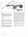
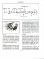
DIFFERENTIAL.
T
•
PINION
T
1HIUS'f WASte
C)
~
:
T
«? ~
~
SlOfGEAI
~j-~
•..•
.---
.~SHAfT
T
T
I
IEAlIHG CAIII9
T
I
/')
T
TI
Removal
Assembly-
Drain the transmission, remove the clutch
housing and engine assembly. Remove the
wheel and axle housings. Remove the brakes
and brake support plates. Remove the differ('ntial bearing carriers.
If a new ring gear is riveted to the carrier
it should be cold riveted. Place the side
gears and pinions in carrier. Rivet the pinion
shaft keeper pin by distorting end of hole.
The gears should have about .005" "backlash
or turned or caused to revolve with a lever
not more than one foot long.
Pull the be.lri,1~s from the carrier. Remove
the pin from the pinion shaft and remove
the shaft. The pinions, side gears and thrust
washers may be moved around to open side
of carrier and removed after the shaft is out.
Inspection
Check the gear teeth and bearings for wear,
roughness or pitting. Check the pinion and
side gears for backlash clearance.
They
should be replaced if backlash is more than
.015" and cannot be compensated by new
thrust washers. Check face of pinions and
side gears and thrust washers and thrust
washer surface in carrier for scoring. Always use new oil seals.
Place the assembly in the case with the ring
gear on the left hand side.
Adjust the bearings by use of the correct
number of shims between the bearing carriers
and transmission case. Adjust to a free rolling fit without end play or binding.
After the bearings are adjusted, the ring gear
mesh may be adjusted by removing a shim
from one side and installing it on the opposite
side. The backlash clearance should be from
.004" to .007". Use a nonsetting sealer between shims and between shims and case and
ca:l'rier to prevent grease leakage.
G - 31
SPECIAL LOW -GEAR
Removal
chipping. Check the shifter shaft for wear at
the detent notches.
Drain the transmission
I
'-.' Assembly'
Separate the t.orque tube from the front of
the transmission
case.
Install pinion gear with shift collar forward.
Install gear with beveled ends of teeth forward. Adjust main shaft bearings to a free
rolling fit without end play or binding. Adjust
pinion shaft bearings to a slightly pre loaded
fit (8 ounce Ft.).
Remove the set screw from the shifter fork
and remove fork and pinion. Remove the
pinion shaft bearing adjusting nut to remove
gear. The shifter rod and detent ball may
be removed by removing the main shaft
bearing retainer and pulling the assembly
from the transmission case. Slide the shaft
from retainer, placing the hand over detent
ball and spring to prevent their loss.
This amount is a noticeable drag, but must
not be so tight that it feels as though the
bearing runs over tight spots. Lock the adjusting nut by punching a portion of the thin
section into the shaft keyway.
Insp'ection
Check the gear teeth and~pfines
'-.7
fO'i'wear"or- _.,.
---.-.
TRANSMISSION
BEVEl
PINION
SHAFT
Removal
Separate engine and clutch housing assembl~ •..
from transmission
case. Separate torque
tube from transmission
case. Remove the
rear axle assemblies,
brakes and brake
support plates and differential.
Remove the
gear shifter mechanism.
Remove the main shaft bearing retainer at
front of case and slide shaft forward
re-
,
moving gears from the shifter opening. Remove the adjusting nut and slide pinion from
rear of case and gears from the shifter opening. Remove the lock from the reverse idler.
shaft and pull shaft to rear of case.
This
shaft is threaded for a puller if required.
Insp'ection
Check the bearings for wear, chipping or
rough cups and rollers.
Check gears for
G - 32
0-
wear and chipped or rough teeth. Check the
shafts for worn splines.
loaded fit, 8 ounce ft. Lock the nut by driving a portion of the thin section into the keyway of shaft.
Assembly
-(j' ..
Tractors without the special low gear will
have a spacer to take the place of the gear.
Place the reverse idle gear, bearings and
shaft in the case first. Install the cork in
the reverse idler ·shaft to prevent loss of
oil.
The main shaft is installed from the front
of case, placing the gears on shaft as it enters
case. Install the rear bearing and the low
speed pinion before installing gear spacer.
Adjust bearings to a free rolling fit without
end play or binding by use of shims between
front bearing retainer and case. The oil dam
for the rear main shaft bearing is installed
behind the bearing.
Install the pinion shaft with the sliding gear,
placing the shift collars towards each other.
Install the loose third speed gear. Install
the thrust washer with the grooved side next
to the third speed gear. Place the spring
washer next, then the bearing and retaining
nut. Adjust the bearings to a slightly pre-
~\
!
G - 33
GEARSHIFT
MECHANISM-_
--
0-
.
.U,JIV!I-;
J 11
rnLEVER GUIDE PINS
LEVER GUIDE_
RAIL
THIRD SPEED
'.
:~
WASHERS
THIRD SPEED SHIFT RAil
ornNT
&AU
& SPRING
...••.
The gear shift is the same as used on the
Model "B-C", except, the guide plate is
notched for the special low gear and the lever
is shaped differently and guide pins are used
to control lever.
either case exists the guide worn excessively
or guide not lining up it may be possible to
shift into two gears at once.
Removal
Remove the seal boot from lever, and remove
the snap ring from transmission case. The
lever and retainer can be lifted frOin the case.
After the lever is out, the two lever guide pins
may be rernoved.
The third speed shift rail can ~e identified
by the three notches. The two front notches
are very close together. The notches are at
right angles to the retaining pin hole. The
third speed fork has the high shift lug. The
fork is installed with the fork towards front
-of case and shaft in R.H. position.
Remove the fo-ur screws attaching the shift
mechanism to-right side of transmission
case.
The low speed shift rail has three notches
in line with the retaining pin ho Ie.
Note the position of the overshift
,
}
Assemblx
The overshift washers should be repla_ced
just as they are removed.
They are used
back of the third speed fork or in front of
the low speed fork, as required, to prevent
gears from rubbing when in the "in gear"
position.
washers.
To remove shift rails pull the retaining pins
from cover. If they cannot be pulled, drive
them on through and cut off excess as it
strikes cover.
The gear shift lever guide pins are cut diagonally and must be installed correctly.
The
right hand pin is installed with the narrow
side of the head up. The left hand pin is
installed with the narrow side of head down.
Check shift rails for wear at detent notches.
Check forks for wear at gear contact section
and lever contact section.
1£the tractor is not equipped with the special
low gears, these pins may be turned over,
and will prevent the shift lever from entering the slot in shift lever guide.
The shift lever guide must be centered to line
up with shifter slots in both forks. The edges
of guide may not be worn excessively.
1£
G-34
STEERING GEAR -
-0
ADJUSTING
SCREW
!(J\
BEARING
COVER-_~
RETAINER
JACKET
TUBE
TUBE CLAMP
1\
BALL ARM
Removal
and housing.
Install jacket tube with the
notch in lower end "up" to prevent grease
leakage. Adjust the length of tube to reach
into recess of steering wheel. It must not
touch wheel or it will cause binding.
Remove the steering gear ball arm and the
two screws attaching steering gear to frame.
Remove the four cover capscrews, cover and
lever shaft. Remove the steering gear wheel
and loosen jacket clamp. Slide jacket tube
up and remove the four capscrews on bearing
retainer.
Back out the lever shaft adjusting screw and
install lever shaft and cover. Count the number of turns from full right to full left, then
turn back half these turns to mid-position.
At mid-position, adjust mesh between worm
and lever shaft to .001" and secure lock nut.
Inspection
Check bearings for wear and roughness.
Check the cam and worm for wear and scor':'
ing. Check the lever shaft bearings for wear.
Steering gear parts must not be worn excessively or steering
adjustment
will be
difficult.
Assembly'
Install the worm shaft and adjust bearings to
a free rolling fit without end play or binding
by use of shims between bearing retainer
When placed on the tractor the steering wheel
should have the first spoke to left of cut-out
section straight up or vertical.
This places
the cut-out section between the 12 0 IC lock
and four o'clock position where greatest' advantage in vision is obtained. This adjustment
is made by lengthening
one tie rod and
shortening the other as required.
Maintain
the "toe-in" of 0" to 1/16" while making this
adjustment. Lubricate the slip joints of socket
and stud rod end to prevent rusting.
G - 35
FRONT AXLE A~D· SPINDLES
Removal
Raise tractor and block securely. Remove
the drag links from the steering arm. Remove the key and n~t f.rom the fronto! radius
rod. Slide 'axle assembly back until free of
tractor.
Check the spindle shafts and radius rod bushings for wear. H worn .020" or more, they
should be replaced.
Assembly'
--
The radius rod bushings are .755" and are
pre-fit. The spindle bushings are 1.126"
and must be reamed after pressing into
--place.
._--
The "toe-in" adjustment of front wheels must
be made each time the axle is repaired or
wheel spacing changed. The "toe-in" is 0"
to 1/16".
o
FRONT WHEELS
Removal
Assembl)l;
Raise the front wheel from floor and block
solidly. Remove the hub cap, key and nut
from axle. Pull wheel. Pull inner bearing
and oil seal. The bearing cups may be driven
from hub.
Always use a new 011 seal. Clean the parts
thoroughly and dry the bearings of cleaning
fluid. Pack with *2 wheel bearing grease.
Adjust
(·nd
playbearingS~'."
or bind41g.a f~ee rolling fit without
Check the bearings for wear, chipping and
roughness.
G - 36
0-
-0
-
-
0-37
~
,I,'
:,',
SPRING
L
~·r
~.:.'-{\t~;l,.•
VALVE COVER~:
N~/
.e'"
VALVE LEVER""
DETENT SPRING~~
~.
SCREW
OIL SEAL
I
"":rCONTROl
A
VALVE
:!
~ COVER STUD
WI .
C)
I
"""
Q)
' ,
--~--~oQ-'
"\
DRIVE GEAR
1~
"
,
.-
1',
:"-'. ~
'/"
[]
"':J I
(JIll
'
,
'
SHIFTARM'r~~
-, -
,':',
0
~
ii'
~vr'fl!!"'·''''
GASKET
•
_
' , ,
,
- - -
THRUST
{J
~8USHING
"
,,',
DRIVE GEAR
SHIFTER PIN
_
WASHER
PLATE
,
,
LUG/~~'
SHIFTER
PUMP BODY
"
.'
~',
BEVEL
\
BEARING
SHAFT NUT
\.
',_,
,
G,
,
"
SEAL RING "
INTAKETUBE~
~'",
'1'{
'Q
" , G",
' , "
'
,
I-GASKET
HYDRA ULIC PUMP
c)
~
o
I
MODEL IIG" HYDRAULIC PUMP
/
General
Pwnp Disassembly
The Model "G" Hydraulic Pwnp is a gear type
pump and develops
approximately
900 P.S.I.
It is driven from the belt pulley and is mounted
on the side of the belt pulley assembly.
Remove the pulley and pinion assembly.
The
surfaces of the pwnp body, gedr plate and pulley
housing are lap fits and mated together with
dowel pins. No gaskets are used. Use great
care when separating
the se parts to prevent
damage to lapped surface.
Oil Circulation
Oi I is drawn through the oil inlet tube which
extends from the pwnp into the reduction gedr
section of clutch housing.
Drilled passages
from the tube through the belt pulley housing
connects the inlet tube to the suction side of the·
gears.
The idler pump gear is pressed onto its shaft
and the shaft is mounted in needle bearings. The
pUmp drive gear is keyed to the shaft.
Remove the cover from the control lever. Drive
the taper groove pin from the lever and valve
and remove lever, The valve has an "0" ring
seal and may be a little difficult but Cdn be
pulled from body.
Oil leaves the gears under pressure through
drilled passages to the relief valve and control
valve. Oil pas se s th-r-ou.gh the control valve
through the drilled hole in valve which connects
the pwnp pressure passage to rdm.
Remove the
and remove
ball. Relief
from spring
When the ram is fully extended the pressure
rides high enough (900) to cause the relief valve
ball to leave its seat. At this ti.me the oil passes
the bdll and returns to the swnp through drilled
passage at "B".
)
pipe plugs from the relief valve bore
relief valve spring, ball seat and
valve seat may 'be driven from body
side. (Enter punch in spring side).
To rt-move pwnp and pulley drive shaft, remove
the detent spring and ball from shift lever.
Remove the bearing cap from housing. Remove
nut on end of shaft and remove the ball bearing.
When the pwnp bypasses the control lever should
be released immediately.
The control lever
spring will then return the control valve to the
hold position.
When in the hold position the
valve is turned so the drilled hole does not line
up with oil passages.
This traps the oil in ram
dnd holds rams extended. Also the wide notch
in valve lines up with pump passage and oil
passes into wide notch and to lower end of valve
and back to swnp through hole" B". When the
pressure drops the relief valve c1oses~
Move shift collar towards bearing and remove
shift pins. Move the shaft assembly towards cap
side of housing until shaft is out of the roller
bearing on the opposite end. Angle shaft and
bring gears and shaft out through large opening
in the pulley housing.
Press the bevel gear from shaft and idler gear
and thrust washer may be removed.
Remove the taper pin from the shiIter and shiiter
shaft and pull lever and shaft assembly from the
housing.
When the control lever is pushed clear down
the valve is rotated further \D\til both the narrow
and wide notches in valve lines up with the pump
drilled passage. At this time the pwnp continues
to force oil through wide notch and under valve
back to swnp through passage "B". Also at the
same time oil from ranl is released through the
narrow notch and back to swnp.
A sc rew is provided on the pwnp control lever
to regulate rate of drop. Turning screw inslows
rate of drop. The belt pulley and pwnp is of the
clutch type. To shift, depress clutch pedal and
move shift lever towards rear of tractor.
Pwnp Removal
Disconnect the ranl hose or hoses, remove control linkage, remove capscrews attaching belt
pulley assen.bly to tractor.
Inspection
Check the bearings for wear and roughness.
Check gears for wear and roughness. Check the
idler gear thrust washe r for wear. Check the
shifter collar and pins for wear.
Check the pump gears for wear dnd end play.
The gear clearance
should be .002" to .004".
Measure the thickness of gear and gear plate to
determine clearance.
Gear backlash should not
be excessive.
If the relief valve is seating
properly and not leaking the pump should develop approximately 900 lbs. pressure.
If it does
not the cause will be found in excessive
gear
backlash or end clearance.
G-39
The relief valve spring should measure 3.131.16";'.~Us_ sealer on outside of needle bearing.
Be
long - free length. If 3/16" short it should be
sure this sealer does not enter bearing. fress
pump idle gear on shaft, locating it in center of
replaced.
Always use new oil seals .and "O!'"
rings .-'"
~ "'
sh~t.
Assembly
Clean·the la'ppedisurfaces,of
PUJnp body, gear
, - section i:Uldhousing throughly and place ,pdrts
Place the.i·dler~g~~~·thrust.wa~hero·n
th~.ih~it~~:;· together on the.l/4",dowelpins.
Late style
Place idler gear next.with sh.ift pip holes ·with .. pumps have' 5/8" dowel pins. Bushings are
counterbored ends towards bevel gear. InstalL.
provided for instdl1ing repair parts on pumps
bevel gear key and press bevel gear on shaft.
having 5/8" holes dnd 1/4" dowel pins. Stdrt
The idler gear should turn free without exc;esthe capscrews and tighten evenly to 30 ft. lbs.
sive end play.· Pldce roller bearing in housing.
U lapped s.urfaces are scrdtched or mdrred or
Enter shaft assembly and place shifter and: pi.ns.
dirt on surface.or capscrews tightened unevenly
in position. Place ball bearing in position with
long side of bearing from snap ring towards the .. the pump will leak ..
gear. Tighten shaft nut securely and 10C;k by
Seat the relief vdlve bdll in its seat before
depressing
a portion of the thin section into
shaft keyway. This bearing is a semi-thrust
assembly; Use a soft punch and use a solid blow.
b~aring and holds the end play of shaft. Install
Drive seat into place ·in side of body closest to
cover using sealer.
trdCtor. Drive to bottom.· E:nter bdll, ball spring
guide,-sp-r-ingand. retaining plug from opposite
side.
Install shift lever .and seal in housing with lever.
pointed away from trador and inside shift lever
Install control valve. with wide notch towards
towards tractor with swivel in shifter collar
groove. Drive taper pin into place. Install detent
tractor side of pump. Install oil seal and control
ball, sprin8.,and plug.
lever, detent ball and spring and cover assembly.
.: '~:';.L:·;!_'
:5'
... ~,
0-
..
Place the pump drive gear key and drive gear
on pump dl;'lve shaft. Install one needle bearing
in drive housing and one in pump cover housing.
~pring in 'control lever cover is
The screw
used to secure slow rate of drop. Turning in on
screw lowers rate of drop.
lI,r
A valve is placed .in the remp.tE .ram
secure deldyed lift of redrfur¢owing
closing this valve.~f:~rtially ,:j~*ases
BELT PULLE Y (NEW STYLE)
Remove the four capscrews attaching the assembly to the belt pulley and pump housing. Remove sheave, shaft nut cover and nut. Pull the
pulley drive flange. Press shaft from housing.
Press bearing from shaft and drive bearing cups
from housing. The snap rings may be left in
place.
Inspection
Inspect gear teeth for wear, and roughnes,,"
Check bearings for wear, roughness or scoring.
Check oil seal surface on pulley hub. Repldce
oil seal.
line to
bar.
)
delay.
Assembly
Assemble
in reverse
of above.
Place the
bearing shield washer with the concave side
towards gear end of shaft and behind beari ng cup.
Install seal with lip towards bearing.
Adjust bearings to a free rolling fit without end
play or binding. Lock nut by depressing a po.rtion
of the thin section into shaft keyway.
Adjust bevel pinion and gear mesh to .005" to
.010" backlash by use of shims between housings.
Use sealer on this shim
----.-/
G-40
)-
BELT PULLEY (OLD STYLE)
Removal
Remove the four capscrews attaching the
pulley assembly to the clutch housing. Remove the cap from pinion shaft and remove
the bearing adjusting nut and pull pulley hub.
Remove the caps from the bevel gear shaft
bearings. Move gear away from pinion as
far as possible. Place two solid blocks between gear and case on pinion side of gear.
Press shaft from gear. Pull pinion from
case. Remove oil seal and bearing cups. It
will not be necessary to remove the snap
rings.
Inspection
Check the bearings for wear, rough or chipped
rollers. Check gear teeth for wear or chipping. Always use new oil seal.
INSTALLING SHAFT
tainers. Adjust bearings to a free rolling fit
without end play or binding, by use of shims
between retainers and case. Adjust gear
backlash to .004" to .007" by removing shim
from one retainer and installing under opposite retainer.
This method will maintain
correct bearing adjustment while securing
correct backlash.
Assembly
Install the pinion in case and the oil seal
with lip towards pinion end of shaft. Adjust
bearings to a free rolling fit without end
play or binding. Lock the bearing adjusting
nut by punching a section of the thin flange
into the shaft keyway. Install the seal cap
over nut.
Use the gasket provided, which is hard paper
.010" thick between pulley and clutch housing.
If a single gasket does not give a gear backlash of .004" to .007" as required, use additional gaskets.
Place the bevel gear in case and press shaft
in against shoulder. Install bearings and re-
G-41
Allis-Chalmers "GU,.