1
इंटरनेट
मानक
Disclosure to Promote the Right To Information
Whereas the Parliament of India has set out to provide a practical regime of right to
information for citizens to secure access to information under the control of public authorities,
in order to promote transparency and accountability in the working of every public authority,
and whereas the attached publication of the Bureau of Indian Standards is of particular interest
to the public, particularly disadvantaged communities and those engaged in the pursuit of
education and knowledge, the attached public safety standard is made available to promote the
timely dissemination of this information in an accurate manner to the public.
“जान1 का अ+धकार, जी1 का अ+धकार”
“प0रा1 को छोड न' 5 तरफ”
“The Right to Information, The Right to Live”
“Step Out From the Old to the New”
Mazdoor Kisan Shakti Sangathan
Jawaharlal Nehru
IS/IEC 1131-2 (1992): Programmable Controllers, Part 2:
Equipment Requirements and Tests [ETD 18: Industrial
Process Measurement and Control]
“!ान $ एक न' भारत का +नम-ण”
Satyanarayan Gangaram Pitroda
“Invent a New India Using Knowledge”
“!ान एक ऐसा खजाना > जो कभी च0राया नहB जा सकता ह”
है”
ह
Bhartṛhari—Nītiśatakam
“Knowledge is such a treasure which cannot be stolen”
( Reaffirmed 2003 )
lS/lEC1131-2(1992)
CONTENTS
1
2
General.......
7
.....................................................
7
1.1
Scope
1.2
Object of the standard
1.3
Object of this part
1.4
Definitions
1.5
Normative references
Service conditions
2.1
and physical environment
2.1.1
Physical environmental
2.1.2
Electrical service conditions
2.1.3
Mechanical
related requirements
conditions
17
.........................
18
...............
and requirements
.............
for transport and storage of modules and subassemblies
2.3.2
Relative humidity
2.3.3
Atmospheric
2.3.4
Free falls
2.3.5
Other conditions
2.3.6
Information to be provided by the manufacturer
21
......................................
pressure
21
..................................
21
............................................
22
.......................................
..............
Transport and storage conditions of PC-systems incorporated
...........................................
control assemblies
22
22
22
.............................................................
General
A.C. and d.c. power supply
24
..............................................
3.2.1
lncomingpowersupply
3.2.2
Memory back-up
3.2.3
Information to be provided by the manufacturer
. ...............
........................
.......................
Digital inputs (current sinking)
3.3.2
Current sourcing digital outputs for alternating
3.3.3
Current sourcing digital outputs for direct current
28
.....................................
currents
.................
......................
Analog outputs
Communication
41
...............................................
3.5.1
General requirements
3.5.2
Information
Main processing
39
.................................................
interfaces
41
...........................................
to be provided by the manufacturer
.......................
unit(s) and memory(ies) of the PC-system
3.6.1
General
3.6.2
Requirements
3.6.3
Information
....................
stations (RIOSs)
.......................
.....................................
Requirements..
3.7.2
Information to be provided by the manufacturer
1
41
42
42
................................................
3.7.1
41
41
..................................................
to be provided by the manufacturer
41
..4 1
....................................................
Remote input/output
35
37
..................................................
3.4.2
32
37
..........................................................
Analoginputs
26
. .. 27
Digital I/OS ........................................................
3.4.1
..2 4
25
...............................................
3.3.1
Analog I/OS
22
in complete
...............................................
3.2
21
21
..........................................
2.3.1
19
21
......................................
Temperature
17
17
service conditions and requirements
3.1
3.7
............
......................................
Normal service conditions
Electrical requirements
3.6
15
., .................
.......................
Requirements
3.5
8
..................................................
2.3
3.4
8
............................................
Special service conditions
3.3
. 7
.........................................
2.2
2.4
3
.....................................................
.......................
42
IS/IEC 1131-2 (1992)
3.8
3.9
3.10
3.1 1
Peripherals
4.2
4.3
4.4
4.5
4.6
4.7
43
3.8.1
Requirements
...........................
.
43
Information to be provided~by the manufacturer
.
44
Noise immunity and emitted noise
................
44
3.9.1
Electrical noise immunity requirements
3.9.2
Information to be provided by the manufacturer
3.9.3
Emitted noise
Dielectric properties
. . . . 45
45
..........................
....................
46
;. .....
General
3.10.2
Dielectric withstand requirements
3.10.3
..............................
Information to be provided by the manufacturer
Self-tests and diagnostics
General
.
..........
46
.
.
48
..............................
48
3.11.2
Requirements
Information to be provided by the manufacturer
requirements
..........................
.
.
46
47
.
.......................
3.11.3
General
44
......
3.10.1
Mechanical
4.1
.................
3.8.2
3.11.1
4
(PADTs, TEs, MMls)
. . . .... .
.
.
.
...........................................................
Protection against electrical shock hazard
48
.
.
48
.
48
48
49
................................
4.2.1
Classlequipment
............................................
49
4.2.2
Class II equipment
............................................
49
4.2.3
Class III equipment and safety extra low voltage (SELV) circuits
Clearance and creepage distances requirements
........
...........................
relating~to normal overvoltage
category
4.3.1
Clearances
4.3.2
Clearances for micro-environment where the voltages are known and
controlled ...................................................
4.3.3
Creepage distances for basic and supplementary
4.3.4
Creepage distances for reinforced insulation
Flammability
requirements
for insulating
4.4.1
Non-metallic
materials
4.4.2
Temperature
limits of materials
Enclosures
materials
..................
insulation
51
............
........................
..........................
58
....................................
4.5.2
Moving parts in non-portable
4.5.3
Enclosures for portable equipment
58
. 59
of enclosures for open equipment (power dissipation)
Terminal connection
mechanical
devices
.............................
.............................
4.6.1~
Constructional
4.6.2
Connecting
4.6.3
Information to be provided by the manufacturer
capacity
Constructional
4.7.2
Protective earthing terminal
Functionalearthing
Interconnecting
requirements
....................................
General
Wiring internal to the PC-system (internal wiring)
4.9.3
Connectors
61
. 62
62
63
....................................................
. 63
.....................
and wiring externals to the PC-system (external wiring) ......
2
61
. 63
.......................................
4.9.2
60
63
.....................................
4.9.1
60
62
..................................................
cables and cords
59
61
.....................
.......................................
4.7.1
4.9
....................................
...........................................
Provisions for protective earthing
4.8
........
...............................
requirements
requirements
53
58
........................................................
Evaluation
52
58
.........................................
4.5.1
50
. 50
. 63
64
WIEC 1131-2 (1992)
4.9.4
4.10
4.11
Plugging/unplugging
..
.
of removable units
.
Battery requirements
4.11.1
4.12
Internal and external wiring
.
General
.
4.11.2
Non-rechargeable
4.11.3
Memory back-up
.... ..
. 65
. . .. .
..
....
. 65
...
....
. 65
batteries
.. ...
..
. .
.
.
General marking requirements
4.12.2
General identification
. ..
65
..
65
66
.
requirements
..
...
.....
67
.
.
67
.............................
........
5.3
Type and contents of written documentation
5.3.1
Catalogues
5.3.2
Users manuals
5.3.3
Technical documentation
.
.
69
.
69
................
5.4
Information
on compliance
5.5
Information
on reliability
Information
67
.
.. .
. 69
.......
and datasheets
.
...
Index of information to be provided
. . . . 69
.
.
.........
69
with this standard
69
..
. .
................
70
.
...
on safety ...................
70
........................
Tests and verifications
General
.............................
6.2
Compliance
with this standard
6.3
Typetests
...........................
. 70
...........
6.3.1
6.3.2
Verification
.
.
procedure
General conditions for tests
6.3.4
Climatic tests
Mechanical
6.3.6
Electrical tests
.
..
.
6.3.3
.
. 71
.
. .
Equipment to be tested
6.3.5
70
..
6.1
6.4
65
.
5.2
5.6
.
.
..
.
4.12.1
General
. 64
.
.
..
...
Markings and identification
. 64
.
.
. .
..
Information to be provided by the manufacturer
5.1
...
.
72
.
. . ... ....
. . 73
.
.
.
.
.
.
. .
. .
.
.
.
Verification
of ac. and dc. power supply characteristics
6.3.8
Verification
of input/output
6.3.9
Verification
of MPU characteristics
6.3.10
Verification
of remote I/O stations
6.3.11
Verification
of peripheral characteristics
6.3.12
Verification
of basic PC-system self-tests and diagnostics
6.3.13
Verification
of markings and manufacturer’s
characteristics
.
..
.
.
.
.
....
. .
.
.
.
.
91
.
98
. 102
. ...
102
. . . 103
.
.
.
.
documentation
103
103
104
. .......
. .
77
a4
..
6.3.7
Routine tests
. 74
.
.
tests
71
.
..
6.4.1
Dielectric strength tests
.
6.4.2
Protective earthing continuity test (withstand test)
104
.
106
.
ANNEXES
A
Illustration
B
Input table equations
C
Recommended
of PC-system hardware definitions
.
.
higher immunity levels for electrical noise tests
D
Correction factors for test voltages
E
Testing of protected outputs .
...
. .
.
107
. ... ..
. .......
3
.
.
.. .
108
.
.
.
109
110
.
..
.
111
As in the Original Standard, this Page is Intentionally Left Blank
MEC
1131-2 (1992)
Indian Standard
PROGRAMMABLE
PART 2
NATIONAL
EQUIPMENT
CONTROLLERS
REQUIREMENTS
AND TESTS
FOREWORD
This Indian Standard which is identical to IEC Publication 1131-2 (1992), issued by the International
Electrotechnical Commission (IEC), was adopted by the Bureau of Indian Standards on the recommendation of the Industrial Process Measurement and Control Sectional Committee (ET 18)and approval of
the Electrotechnical Division Council.
This standard constitutes Part 2 of a series of standardson Programmable Controllers and their associated
peripherals and should be read in conjunction with the other parts of the series.
The following standards are being brought out in this series:
Programmable controllers:
Part 1 General information
Part 2 Equipment requirements and tests
Part 3 Programming languages
Part 4 User guidelines
Part 5 Communications
The text of IEC Standard
deviations.
has been approved
as suitable for publication
as Indian Standard
without
CROSS REFERENCES
In this adopted standard, reference appears to certain International Standards for which indian Standards
also exist. Thecorresponding
Indian Standards which are to be substituted in their place are listed below
along with their degree of equivalence for the editions indicated:
Degree of
Corresponding Indian Standard
lnrernational Standard
Equivalence
IEC 38 (1983)
IS 12360 : 1988 Voltage bands for electrical installations including preferred voltages and frequency
Technicaly
equivalent
IEC50-151
IS 1885 (Part 57) : 1982 Electrotechnical
Part 57 Electric and magnetic circuits
vocabulary:
Technically
equivalent
IEC 50-441 (1984)
IS 1885 (Part 17) : 1979 Electrotechnical vocabylary:
Part 17 Switchgear and controlgear (first revision)
Technically
equivalent
IEC 60-l (1989)
IS 2071 (Part 1) : 1993 High voltage test techniques:
Part I General definitions’ and test requirements
(second revision)
Identical
(1978)
IEC 68-2-l (1990)
IEC 68-2-2 (1974)
IEC 68-2-3 (1969)
IEC 68-2-6 (1982)
IEC68-2-14 (1984)
IEC 68-2-27 (1987)
IEC 68-2-30 (1980)
IEC 68-2-31 (1969)
IEC 68-2-32 (1975)
IS 9000 Basic environmental testing for electronic
and electrical items (series)
IS 9001 Guidance for environmental testing (series)
IS 9002 Equipment for environmental
tests for
electronic and electrical items (series)
Technically
equivalent
IEC 85 (1984)
IS 1271 : 1985 Thermal evaluation and classification
of insulation (first revision)
Technically
equivalerit
IEC 112 (1979)
IS 2824 : 1975 Method of determining the comparative tracking index of solid insulating materials under
moist conditions (first revision)
Technicaly
equivalent
5
ISAEC 1131-2(1992)
International
Corresponding
Standard
Degree of
Equivalence
Indian Standard
IEC 529 (1989)
IS 4691 : 1985 Degrees of protection provided by
enclosure for rotating electrical machinery
Technically
equivalent
IEC 664 (1980)
SP 39 : 1987 Guide for insulation co-ordination
low voltage systems
Technically
equivalent
IEC 695-2-l
IS 11000 (Part 2/Set 1) : 1984 fire hazard testing: Part
2 Test methods, Section 1 Glow wire test and guidance
Identical
IEC 707 (1981)
IS 11731 (Part 1) : 1986 Method of test for the determination of the flammability of solid electrical insulating
materials : Part 1 Horizontal specimen method
IS 11731 (Part 2) : 1986 Method of test for the
determination of the flammability of solid electrical
insulating materials : Part 2 Vertical specimen method
Technically
equivalent
IEC 947-l
IS 13947 (Part 1) : 1993 Low-voltage switchgear
controlgear : Part 1 General rules
IEC 947-5-l
(1980)
(1988)
(1990)
IEC 950 (1991)
within
and
Identical
IS 13947 (Part 5/Set
1) : 1993 Low-voltage
switchgear and controlgear: Part 5 Control circuit
devices and switching elements, Section 1 Electromechanical control circuit devices
Identical
IS 10422 : 1982 Requirement and test methods for
safety of data processing equipment
Technically
equivalent
The concerned technicakommittee
has reviewed the provisions of following IEWISO standards referred
to in this adopted standard and has decided that it is acceptable for use in conjunction with this standard:
IEC 255-4 (1976) Electrical
dependent-specified time
relays -
Part 4 : Single input energizing
quantity
measuring
relays with
IEC 364-4-443 (1990) Electrical installations of buildings - Part 4 : Protection for safety - Chapter 44 :
Protection against overvoltages - Section 443 : Protection against overvoltages of atmospheric origin or
due to switching
IEC 417 (1973) Graphical symbols for use on equipment-index,
survey and compilation of the single sheets
IEC 445 (1988) Identification of equipment terminals of certain designated conductors,
rules of an alphanumeric system
including
general
IEC 801-2 (1991) Electromagnetic compatibility for industrial-process
ment - Part 2 : Electrostatic discharge requirements
measurement
and control equip-
IEC 801-3 (1984) Electromagnetic compatibility for industrial-process
ment - Part 3 : Radiated electromagnetic field requirements
measurement
and control equip-
IEC 801-4 (1988) Electromagnetic compatibility for industrial-process
ment - Part 4 : Electrical fast transient/burst requirements
measurement
and control equip-
IEC 801-5 (. . . ) Electromagnetic compatibility for industrial-process
ment - Part 5 : Surge immunity requirements (under consideration)
measurement
and control equip-
IEC 947-5-2 (1992) Low voltage switchgear and controlgear
switching elements - Section 2 : Proximity switches
-
Part 5 : Control
circuit devices and
ISOAEC 9506-l (1990) Industrial automation systems Service definitions
Manufacturing
message specification
-
Part 1 :
ISOAEC 9506-2 (1990) Industrial automation systems Protocol specification
Manufacturing
message specification
-
Part 2 :
Only the English language text given in the International Standard has been retained while adopting it as
Indian Standard, and as such the page numbers given here are not the same as in IEC publication.
For the purpose of deciding whether a particular~requirement of this standard is complied with, the final
value, observed or calculated, expressing the result of a test, shall be rounded off in accordance with IS 2 :
1960 ‘Rules for rounding off numerical values (revised)‘. The number of significant places retained in the
rounded off value should be the same as that of the specified value in this standard.
6
rs/IEC 1131-2 (1992)
1
General
1.1
Scope
This international
Standard applies to programmable controllers and their associated
peripherals such as programming and debugging tools (PADTs), test equipment (TE) and
man-machine interfaces (MMls), etc.
Equipment covered in this standard is intended for use in overvoltage category II (see
IEC 364-4-443), in low voltage installations, Where the rated mains supply voltage does
not exceed 1 000 V a.c. (50/60 Hz), or 1 500 V d.c., for the control and command of
machines and industrial processes.
Programmable controllers and the associated peripherals are considered as components
of a control system and may be provided as enclosed or open equipment. Therefore, this
standard does nor deal with the automated system in which the programmable controller
system is but one basic compo.nent among many others including its application program.
Since programmable controllers are component devices, overall automated system safety
including installation and application is beyond the scope of this standard. For further
information, refer to IEC 1131-4 which is intended to help users in reducing the risks. However, electrical noise immunity and error detecting of the PC-system operation such as the
use of parity checking, self-testing diagnostics, etc., are addressed.
1.2
Object of the standard
The purposes of this standard are:
to establish the definitions and identify the principal characteristics relevant to the
selection -and application of programmable controllers and their associated peripherals;
-
- to specify the minimum requirements for the functional characteristics,
service
conditions, construction characteristics, general safety, and tests applicable to programmable controllers and the associated peripherals;
- to define, for each of the most commonly used programming languages: major field
of application, syntactic and semantic rules, simple but complete basic sets of programming elements, applicable tests and means by which manufacturers may expand or
adapt those basic sets to their own programmable controller implementations;
-
to give general tutorial information and application
guidelines
to the user;
lS/lEC 1131-2 (1992)
-- to define the communication between programmable controllers and,other electronic
systems
using
the Manufacturing
Message
Specification
(MMS)
defined
in
ISO/IEC 9506.
1.3
Object of this part
This part specifies
- the electrical, mechanical and functional* requirements for programmable controllers and the associated peripherals
and the service, storage and transportation
conditions that apply;
-
the information that the manufacturer
is required to supply;
- the test methods’* and procedures that are to be used for the verification of
compliance of programmable controllers and their associated peripherals with the
requirements.
1.4
Definitions
NOTE - This clause contains the definitions
of terms
order to make it more self-contained.
Terms of general
1.4.1
accessible
which are more specific to the object
use are defined in part 1.
of this part in
part:
1) A part which can be touched by the standard jointed test finger (see IEC 529) .
2) A conductive part which can readiiy be touched and which is not normally
which may become live under fault conditions. [IEV 441--l 1-l 0 modified1
1.4.2 basic PC-system(s):
figure 1, in 3.1 and 6.3.1.
1.4.3 battery:
rechargeable.
1.4.4
Representative
An electrochemical
energy
configuration(s)
source
live, but
used for type tests.
which ma!! be rechargeable
See
or non-
circuit, class I, class II, class Ill: see equipment (1.4.16).
1.4.5 clearance:
The shortest distance between two conductive parts, or between a
conductive part and the bounding surface of the equipment, measured through air. The
bounding surface -is the outer surface of the enclosure considered as though metal foil is
pressed into~contact with accessible surfaces of insulating material.
1.4.6 coating, protective: A coating of suitable insulating material that covers the clearance and/or creepage distance of the printed board and conforms to the surface of the
board in such a manner that the environment is excluded and the clearance and/or
creepage distance can withstands the required impulse and continuous potentiak
.
Functional
. . The tests
controller
requirements
are
type
systems
tests
are contained
or production
in both the electrical
routine
tests,
are applied.
8
and
and mechanical
clauses.
not tests- related
to the ways
programmable
iS/iEC 1131-2 (1992)
NOTE - Coati,ng is normally applied to exclude the effects of atmosphere and to increase the dielectric
properties of the clearance -and/or creepage distances which wquid not normally be adequate without
coating. Less effective coating may exclude the atmosphere but cannot be relied on to enhance the
dielectric properties.
1.4.7 comparative tracking index (WI): The numerical value of the maximum voltage at
which a material withstands 50 drops of NH,Ci solution (ammonia chloride) without
tracking (see IEC 112).
1.4.8 coverage factor (for modules, units, external wiring, internal wiring, removable
cables, interconnections
and functions):
The percentage of modules, units, external
wirings, internal. wirings, removable cables, interconnections,
functions, whose removal,
absence or failure is detected by built-in test functions or by a suitable test program along
with a proper functioning verification procedure. See 6.3.2.
1.4.9 creepage distance: The shortest path between two conductive parts, or between a
conductive part and bounding conducting surface of the equipment, measured along the
surface of the insulation.
1.4.10
current sinking: The act of receiving current.
1.4.11
current sourcing: The act of supplying current.
1.4.12
diverstty
factor (of an output module): Ratio of the permissible total current
(total output current) to the sum of ail maximum rated currents of multi-channel output
module operating at the most adverse combination of normal service conditions.
1.4.13
earth: The conducting mass of the Earth, whose electric potential at any point is
conventionally taken as zero. [IEV 151-01-07) (Synonymous with protective earth.)
1.4.14
earth, functional,
protective:
1) functional
earth: A low impedance path between electrical
non-safety purposes such as noise immunity improvement.
circuits
and earth for
2) protective
earth: A low impedance path under fault conditions including high
voltage and/or current between the electrical circuit and earth to minimize the risk to
the operator.
1.4.15
enclosure:
A final mounting housing
dental contact with live and/or moving parts.
enclosed.)
which provides protection against acci(See equipment, open and equipment,
1.4.16
equipment (or circuit) class I, class ii, class Iii: Class numbers designate the
means by which electric shock protection is maintained in normal use and likely fault
conditions of the installed equipment.
1) class I clrcult or equipment: Circuit or equipment in which protection against
electric shock does not rely on basic insulation only, but which includes an additional
safety precaution in that accessible conductive parts -are connected to the protective
9
WIEC 1131-2 (1992)
earthing_ conductor in the fixed wiring of the installation in such a way that they cannot
become live in the event of a failure of the basic insulation. For equipment intended for
use with a flexible cord, this provision includes the protective earthing conductor as
part of the flexible cord.
NOTE - Class I equipment may have parts with double insrlation or reinforced insulation, or parts operating at safety extra-low voltage.
2. class II clrculf or equlpment: Circuit or equipment in which protection against
electric shock does not rely on basic insulation, but in which additional safety precautions, such as double insulation or reinforced insulation are provided, there being
no provision for protective earthing or reliance upon installation conditions.
Such equipment may be of one of the following types:
insulation-emncased class II equipment: equipment having a durable and
i)
substantially continuous enclosure of insulating material which envelops all conductive parts, with the exception of small parts, such as nameplates, screws and
rivets, which are isolated from parts at hazardous voltage by insulation at least
equivalent to reinforced insulation;ii)
metal-encased class II equipment: equipment having a substantially continuous
metal enclosure, in which double insulation is used throughout, except for those
parts where reinforced insulation is used;
iii)
equipment which is a combination
of types i) and ii).
NOTES
1
The insulated enclosure of a class II equipment may form a part of the whole of the supplementary
insulation or of the reinforced insulation.
2
If equipment with doubfe insulation and/or reinforced insulation throughout has a protective earthing
terminal or contact, it is deemed to be of class I construction.
3
class II equipment may have parts operating at safety extra-low voltage.
3) class Ill clrcult or equlpment: Circuit or equipment in which protection against
electric shock is provided by circuits supplied by safety extra-low voltage (SELV) and
where voltages generated do not exceed the limits for SELV.
1.4.17
equlpment,
enclosed:
Equipment which is enclosed on all sides with the possible exception of its mounting surface to prevent personnel from accidentally touching live
or moving parts contained therein and to protect the equipment against ingress of medium
size solid foreign bodies, and meeting requirements of mechanical strength, flammability,
and stability (where applicable).
1.4.18
equlpment,
fixed: Equipment which is part of the permanent installation.
1.4.19
equipment, hand-held- portable: Equipment which is intended to be held in one
hand while being operated with the other hand.
1.4.20
equipment,
open: Equipment which may have live electrical Parts accessible,
e.g. a main processing unit. An open equipment is to be incorporated into other
assemblies manufactured to provide safety.
10
IS/IEC 1131-2 (1992)
1.4.21
equipment, on-line pluggable: Equipment which can be plugged or unplugged
from the PC-system at any time including when the PC-system is operating, without
disturbing or disrupting the normal operation of the PC-system and without any increased
risk to the operator and the application.
1.4.22
equipment, portable: Enclosed equipment which is -intended to be transported by
htind-carrying, such as programming and debugging tools (PADTs) and test equipment (TE).
1.4.23
hazardous voltage: Voltage exceeding 42,4 V peak or d.c., existing
which does not meet the requirement for a limited energy circuit.
in a circuit
immunity: Ability of the PC-system to be unaffected or to maintain its operation
1.4.24
within limits specified by the manufacturer when submitted to influencing quantities
specified in this standard.
1.4.25
input, digital, type l/type 2 (type 1 dlgltai input, type 2 digital input):
1) type 1 digital Input: Digital input for sensing signals from mechanical contact
switching devices, such as relay contacts, pushbuttons, switches, etc.; type 1 digital
inputs -may not be suitable for use with solid state devices such as sensors, proximity
switches, etc.
2) type 2 digital input: Digital input for sensing signals from solid state switching
devices such as e-wire proximity switches. This class could also be used for type 1
applications.
1.4.26
insulation
(basic, supplementary,
1) basic insulation:
electric shock.
Insulation
double, relnforced):
applied to live parts to provide basic protection
against
2) supplementary
insulation: Independent insulation applied in addition to basic
insulation in order to ensure protection against electric shock in the event of a failure of
the-basic insulation.
3) double
insulation.
insulation:
Insulation
comprising
both basic insulation
and supplementary
4) reinforced insuiatton:
Single insulation system applied.to live parts which provides
a degree of protection against electric shock equivalent to double insulation under the
conditions specified in this standard.
NOTE - The term ‘insulation system’ does not imply that the insulation must be in one homogeneous
piece. It may comprise several layers which cannot be individually tested as supplementary or basic
insulation.
interface: Shared boundary between a considered system and another system,
1.4.27
or between parts of a system, through which information is conveyed. See 3.1.
1.4.28
Isolated
between them.
1.4.29
(devices,
circuiis):
Devices, -circuits with no galvanic connection
live part: Any conductor or conductive part which is at a voltage in normal use.
11
IS/IEC 1131-2 (1992)
1.4.30
mains power supply: Power from the conductors/mains
lation of the building at the supply voltage to the PC-system.
of the permanent instal-
1.4.31
maln processing
unit (MPU): The portion oft the PC-system which interprets or
executes the (main part of the) application program. The MPU may include power supply,
memory, and I/OS. See annex 6 of IEC 1131-l and 3.1, 3.6 and annex A of this part.
1.4.32
man-machine
interface (MMI): Manufacturer’s catalogued peripheral equipped
with pushbuttons, lamps, keyboards, displays or equivalent, intended as operator interface, such aspmotor control/mo_nitor panel, general purpose operator interface, etc.
MMls may be part of the permanent
boards, etc.) or not.
installation
(e.g. mounted on front panels,
1.4.33
material group: Classification
tracking index (CTI) range (see 4-.3.3).
of insubting
1.4.34
micro-environment:
Ambient
creepage distance under consideration.
conditions
materials
which
doors,
in terms of comparative
surround
the
clearance
or
NOTE - The micro-environment of the clearance or creepage distance and not the environment of the
equipment determines the effect of the insulation. The micro-environment may be better or worse than the
environment of the equipment. It includes all factors influencing the insulation, such as climatic, electromagnetic, pollution, etc. (See IEC 664 for further information.)
1.435
module: Device such~ as an I/O board assembly which plugs into a- back plane-
.or base.
1.4.36
multi-circuit
module: Module containing multiple isolated circuits. With respect
to I/O modules, a module containing multiple isolated user signal interfaces.
1.4.37
multi-channel
module: Module containing multiple input and/or output
signal interfaces. A multi-channel module may or may not be a multi-circuit module.
1.4.38
output, not-protected,
protected,
See 3.3.2.2 and 3.3.3.2.
short-circuit
user
proof:
1.4.39
overvoltage
category (of a circuit or within an electrical system): A conventional number based on limiting (or controlling) the values of prospective transient
overvoltages occurring in a circuit (or within an electrical system having different nbminal
voltages) and depending upon the means employed to influence the overvoltages.
NOTE - In an electrical system, the transition from one overvoltage category 14 another of lower category
is obtained through appropriate means complying with interface requirements, such as an overvoltage
protective device or a series-shunt impedance arrangement capable of dissipating, absorbing, or diverting
the energy in the associated surge current, to lower the transient overvoltage value to that of the desired
lower overvoltage category.
1.4.40
PC-system: Synonymous with programmable controller system as defined
2.5.1 of IEC 1131-l. see annex A of IEC 1131-l and annex A of this part.
12
in
IS/IEC 1131-2 (1992)
1.4.41
permanent installation:
See annex A of IEC 113i-1 or annex A of this part.
pollution degree (in the micro-environment):
For the purpose of evaluating
1.4.42
clearances and creepage distances, the following three degrees of pollution in the microenvironment are estabfished:
1) -pollution degree 1: No pollution
pollution has no influence.
or only dry, non-conductive
pollution
occurs. The
2) pollution
degree 2: Normally, only non-conductive pollution occurs. Occasionally,
however, a temporary conductivity caused by condensation shall be expected.
3) pollution
degree 3: Conductive pollution occurs, or dry, non-conductive
occurs which becomes conductive due to condensation which is expected.
pollution
NOTES
1
The conductivity
of a polluted insulation
The minimum clearances
2
fundamental data.
1.4.43
protective
is due to the deposition
of foreign matter and moisture.
given for pollution ~degrees 2 and 3 are based on experience
earthing
conductor,
termlnal,
connection:
rather than on
See earth, protective
(1.4.14).
rated supply WItage: Mains voltage jfor three-phase
1.4.44
voltage) for which the manufacturer has designed the apparatus.
supply,
the line-to-line
recurring peak voltage: Peak value of a generated voltage whose characteristic
1.4.45
is recurring at some specified period. Such recurring peak voltages are generally
generated in switch-mode
power supply circuits (a.c. or d.c. to d.c. converters).
See 4.3.3.2.
1.4.46
removable connector:
Connecting means intended to be used for operation or
maintenance servicing of the PC-system by the user. Pluggable modules, peripherals, etc.
are generally connected to the rest of the PC-system by such means.
1.4.47
safety extra-low voltage (SELV): A voltage which, under all operating
conditions does not exceed 42,4 V peak or dc. between conductors, or between any
conductor and earth, in a circuit which is isolated from the mains power supply by means
of a safety isolating transformer or an equivalent means. National regulations have to be
considered for a correct isolation voltage rating.
safety extra low-voltage circuit (SELV circuit): Circuit which is so designed
1.4.48
and protected that under normal and single fault conditions the voltage between any two
accessible parts, one of which may be earth or a conductive accessible part connectedto
earth, does not exceed the safety extra-low voltage and in which overvoltages higher than
SELV are- not ~generated.
1.4.49
Subassembly:
Synonymous
with unit (1.4.53).
13
WIEC 1131-2 (19921
1.4.50
temperature
(amblent air):
1) For enclosed non-ventilated equipment that is cooled by natural air convection, the
equipment ambient air temperature is the room temperature 1 m away from the surface
of the enclosure on a horizontal plane located at the vertical mid-point of the enclosure.
2) For enclosed ventilated equipment,
temperature of the incoming air.
the equipment
3) For open equipment, the ambient air temperature
air immediately below the equipment.
ambient
temperature
is the temperature
is the
of the incoming
1.4.51 total output current (of an output module): The )current that a multi-channel
module operating at the most adverse combination of normal service conditions can
supply without any part of it (insulation, terminals, exposed conductive parts, etc.) exceeding the specified temperature limits.
NOTE
currents
1.4.52
- For a multi-channel
of the channels.
test (routine,
module, the total output current is generally
type, immunity
type, withstand
less than the sum of the output
type):
1) routlne test: Test to which each individual catalogued device is subjected during or
after its manufacturing process to ascertain whether it complies with certain criteria.
2) type test: Laboratory test to which one or several basic PC-systems or samples of
catalogued devices is (are) subjected to ascertain that its (their) design(s) meet requirements expressed in this itandard.
3) Immunity typ~e test (immunity test): Type test- verifying that the basic PC-system
operation is not altered by the application of specified influencing quantities which are
intended to approximate normal service conditions.
During the test, the basic PC-system executes
vided by the manufacturer (see 6.3.2.2).
NOTE
- Some tests may allow temporary
must be then specified by the manufacturer.
alteration
appropriate
test programs
of the basic PC-system
operation
to be pro-
within
limits
that
4) withstand
type test (withstand
test): Type test verifying that the application of
more severe influencing quantities to the basic PC-system does not impair its ability to
assumes its intended mission-. Unless otherwise specified, the basic PC-system is not
energized during the withstand test. After a specified recovery period, a proper functioning verification
procedure is performed as specified to check visually and/or by
measurement that the test had~no detrimental- effect on the basic PC-system.
NOTE
- The impact test (see 6.3.5.5.1)
of the basic PC-system.
is classified
as withstand
test though it may affect the operability
1.4.53
unit: For the purpose of this standard, a unit is an integral assembly (which may
consist of modules plugged in or otherwise connected within the assembly) and which is
connected to other units within the system by means of cables for permanently installed
units and cables or other means for portable units.
14
IS/IEC 1131-2 (1992)
1.4.54
wiring (Internal, external):
1) Internal wlrlng: Wiring which is irrside the open or enclosed PC-system equipment.
2) external wlrlngYWiring of the PC-system equipment
the user.
1.5
which is normally installed
by
Normative references
The following normative documents contain provisions which, through reference in this
text, constitute provkions of this part of IEC 1131. At the time of publication, the editions
indicated were valid. All documents are subject to revision, and parties to agreements
based an this part of IEC 1131 are encouraged to investigate the possibility of applying
the most recent editions of the normative documents indicated below. Members of CECand
IS0 maintain registers of currently valid International Standards.
-IEC 38: 1983, IECstandard
voltages.
IEC 50(151): 1978, international
magnetic devices.
Electrolechnical
IEC SO(441): 1984, international
cont:olgear and fuses.
Becfrotechnical
IEC 60-l : 1989, High-voltage
requirements.
lest techniques
Vocabulary - Chapter 151: Electrical and
Vocabulary
-
Part
- Chapter 447: Switchgear,
1: General
definitions
IEC 68-2-l : 1990, Environmental
testing - Part 2: Tests - Tests A: Cold.
IEC 68-2-2: 1974, Environmental
testing - Part 2: Tests - Tests B: Dry heat.
IEC 68-2-3: 1969, Environmental
state.
IEC 68-2-6: 1982, Environmental
(sinusoidal).
IEC 68-2-14:
rature.
and test
testing - Part 2: Tests - Test Ca: Damp heat, steady
testing - Part 2: Tests - Test Fc and guidance:
1984, Environmental
Vibration
testing - Part 2: Tests - Test N: Change of tempe-
IEC 68-2-27: 1987, Environmental
testing - Part 2: -Tests - Test Ea and guidance: Shock.
IEC 68-2-30: 1980, Environmental
heat, cyclic (12 + IPhour cycle).
testing - Part 2: Tests - Test Db and guidance: Oamp
IEC 68-2-31: 1969, Environmental testing - Part 2: Tests - Test EC: Drop and topple,
prim;jlrily for equipment-t)pe specimens.
15
IS/IEC 113%2(1992)
IEC 66-2-32: 1975, Environmental
testing - Part 2: Tests - Test Ed: Free fall.
IEC 85: 1984, Thermal evaluation and classification
of electrical insulation,
IEC 112: 1979, Method for determining the comparative
solid insulating materials under moist conditions.
and the proof tracking indices of
IEC 255-4: 1976, Electrical relays - Part 4: Single input energizing
relays with dependent specified time.
quantity
measuring
IEC 364-4-443: 1990, Electrical installations of buildings - Part 4: Protection for safety against
Chapter 44: Protection
against overvoltages - Section 443: Protection
overvoltages of atmospheric origin or due to switching.
IEC 417: 1973, Graphical symbols for use on equipment - Index, survey and compilation
of the single sheets.
IEC 445: 1988, identification of equipment terminals and of terminations
designated conductors, including general rules of an alphanumeric system.
of certain
IEC 529: 1969, Degrees of protection provided by enclosures (IP Code).
IEC 664: 1980, Insulation co-ordination
and creepage distances for equipment.
within low-voltage systems including
clearances
IEC 695-2-l : 1960, Fire hazard testing - Part 2: Test. methods - Glow-wire
guidance.
IEC~707: 1981, Methods of test for the determination of the flammability
insulating materials when exposed to an igniting source.
IEC 601-2: 1991, Electromagnetic compatibility for industrial-process
control equipment-- Part 2: Electrostatic discharge requirements.
test and
of solid electrical
measurement
and
IEC 801-3: 1984, Electromagnetic compatibility for industrial-process
measurement
COntiOl equipment - Part 3: Radiated- electromagnetic
field requirements.
and
IEC 801-4: 1988, Electromagnetic compatibility for industrial-process
control equipment- - Part 4: Electrical fast transientiburs t requirements.
measurement
and
IEC 801-5: 199X, Electromagnetic compatibility for industrial-process
measurement
control eguipment~- Part 5: Surge immunity requirements (under consideration).
and
I
IEC 947;l: 1988, Low-voltage
switchgear and controlgear - Part 1: General rules.
IEC 947-5-l: 1990, Low-voltage switchgear and controlgear - Part 5: Control circuit
devices and switching elements - Section One: Nectromechanjcal control circuit devices.
16
IS/IEC 1131-2 (1992)
IEC 947-5-2:
1992, Low voltage switchgear and controlgear - Part 5: Control
devices and switching elements - Section 2: Proximity switches.
IEC 950: 1991, Safety of information
equipment.
technology equipment,
ISOAEC 9506-1, 1990: lndustfial automation
caution - Part 1: Service definition.
including electrical business
systems - Manufacturing
ISO/IEC 9506-2: 1990, Industrial automation systems - Manufacturing
tion - Part 2: Protocol specification.
2
Service conditions
2.1
and physical envtronment
circuit
Message Specifi-
Message Specifica-
related requirements
Normal service conditions
It is the user’s
exceeded.
2.1 .l
responsibility
Physical environmental
2.1.1.1
to ensure
that the following
service
conditions
are not
conditions
Operating ambient air temperature
Operating~temperature
ranges are given by the following table 1.
Table 1 - Operating ambient air temperature of PC-systems (“C) (note 1)
Enclosed equipment
(ventilated/non-ventilated)
Type of
timit
Open equipment
(note 2)
Permanent
insta\lation
Non-permanent
installation
Permanent
installation
Non-permanent
installation
Temperature
Max.
range
Min.
40
5
40
5
55
5
T InPX.(mm 3)
Tmin.(note 3)
Averagetemperature
over24 h
Max.
35
35
50
T.” (note 3)
NOTES
1
See definitions in 1.4.50 and in annex A.
2
Open equipment is designed to be mounted within an enclosure where the equipment
ambient air temperature which is measured immediately below each individual assembly may
be up to 15 ‘C above the maximum room ambient air temperature.
No forced external cooling is assumed (seC 4.5.1).
Open peripherals which are intended to be permanently installed as part of the PC-system shall
~meet the operating temperature range of the PC.
3 -Equipment ambient air temperature-limits (T,,.,,,,, T,“, T,,,,,,) for open peripheral equipment
not intended to be permanently installed shall be specified by the manufacturer.
,
17
IS/IEC 1131-2 (1992)
2.1.1.2
Storage temperature
The allowable temperature
2.1.1.3
range is -25 “C to +70 “C.
Relative humidity
The manufacturer
may select one of the two following levels.
Table 2 - Operating ambient air relative humidity (notes 1 and 2)
Relative
Relative
humidity severity level
humidity range
RH-1
5O%toQ5%
RH-2
5 % to 95 %
NOTES
I
2.1.1.4
1
Non-condensing.
2
See 2.1.2.2
discharge
requirements.
Pollution degree
The manufacturer
2.1 .1.5
for electrostatic
shall specify the pollution degree for which the equipment is suitable_
Corrosion immunity
Corrosion conditions vary widely depending on the application and it is not possible
specify normal conditions of use. In case of severe service conditions, see 2.2.
to
The manufacturer
IEC 68.
to
2.1.1.6
shall specify
the corrosion
immunity
of the equipment
according
Altitude
The equipment shall be suitable for operation up to 2 000 m.
2.1.2
2.1.2.1
Electrical service conditions and requirements
A.C. and d.c. mains power supply
Refer to 3.2.
2.1.2.2
Electrical noise conditions
Electrical noise conditions vary widely and depend on the installation
installed equipment and its proximity to the PC-system.
wiring and other
For the purpose of this standard, the minimum noise conditions to which’ the PC-system
shall be immune are indirectly expressed by the requirements given in 3.9.1.
18
For electrostatic discharge (ESD) the manufacturer may select one of the severity levels of
the following table 3. Refer to IEC 801-2 for description of classes of installation.
Table 3-
Electrostatic discharge service conditions
(cowfinated
Class d installation
to IEC 801-2)
fevek
ESD sevdy
[
with relative Iwnidhy
severtty levels) {note)
(acccrdiw
Level R1-1-l
Level ESD-3
3
Level RH-2
Leve! ESD-4
4
!
: FK.)TE- See table 2 for ddinilkm
2.1.2.3
of relalive humidity ~everity levels.
Overvoltage category. Cofftroi of transient
cwervdtages
The nature of the installaticm shall be such that overvoltage category II conditions shall not
be exceeded.
Transient overvdtages at the point of connection to the mains power
controlled rmt to exceed overvoltage category 1[, i.e. not higher than the
corresponding to Ii?e rated voltage far basic insulation. The equipment
suppression means shaH be capable of absorbing the energy in the
3.10.2.)
2.1.2.4
supply shall be
impulse voltage
or the transient
transient. {See
Non-periodic ovewcdfages
In the industrial environment, non-periodic overvoltage peaks may appear on mains power
supply lines as -a result of power interruptions to high energy equipment (e.~. bio.wn fuse
on one branch in d .3-ptiase system). This will cause high current pulses at relatively low
s@Ps to
voltage levels (approximately 2 x uP~ak). 1~~ user s~al~ t~k~ the ~ec=sw
prevent damage to the PC-system (e.g. by interposing a transformer). See lEC 1131-4 for
additional irrformation.
2.1.3
Mechanical
service conditions
an~ requirements
Vibration, shock and free fall conditions vary widely depending on the installation
environment and are very difficult to specify.
and
For the purpose of this standard, the service conditicms are indirectly defined by the following test requirements which appiy to fixed equipment as weii as to unpackageff porfabie
and hand-heid portable equipment (see exceptions in 2. f ,3.2). They do not appiy to
equipment containing assemblies other than PC-systems andlor associated peripf’terais.
Experience shows that equipment passing these tests are suitabie tor industrial use on
sfationa~ installations.
2.1.3.1
Vibrations
fmmunity rffquirernents are:
19
IS/lEC 113%2(1992)
Table 4 - Sinusoidal
vibrations
service conditions-for
Frequency range
HZ
PC-systems (notes~ 1, 2 and 3)
Occasional
Continuous
0.0375 mm amplitude
0,075 mm amplitude
57$f<150
05 g constant acceleration
1,O g constant acceleration
150< f
Not defined
Not defined
lOSf<57
NOTES
1
Applicable to each of three mutually- perpendicular
2
Test according to IEC 66-2-6, test Fc.
3
The manufacturer shall specify
peripherals on the test equipment.
2.1.3.2
the method
axes.
of mounting
portable
and hand-held
portable
Shocks
Immunity requirements are: Occasional excursions
three mutually perpendicular axes (IEC 68-2-27).
to 15 g, 11 ms, half-sine,
in each of
NOTES
1
Devices containing CRTs are excluded from this requirement.
2
EleetromechaniGal relays may temporarily respond to 15 g shocks. Temporary
allowed during the test, but equipment should be fully functional after the test.
malfunctioning
Free falls
2.1.3.3
Immunity requirements
for type tests are:
Table 5 - Free fall on concrete floor
(Applicable to portable and hand-held portable equipment)
Portable and hand-held
portable
(Any weight)
(Withstand)
Supported drops
(Any weight)
(Immunity)
1 000 mm; 2 trials
Random drops
Flat drops
Hand-held portable
Notes
1 and 2
100 mm; 2 trials
1
30” or 100 mm; 2 trials
1 and 3
NOTES
1
Caution: Temporary malfunctioning is allowed at the impact, but equipment shall be fully functional after the test and not cause a shock hazard. Therefore; if equipment is operating during the
fall, erroneous operation could be introduced upon impact which may require operator correction.
2
From prescribed~altitude
3
From~prescribed values given in 3.2.1 of IEC 66-2.31.
(normal position of use) see IEC 66-2-32, Procedure 1.
20
is
IS/lEC 1131-2 (1992)
2.2
Special service conditions
When the service conditions are more severe than those given in 2.1, or other adverse
environmental conditions exist, (e.g. air pollution by dust, smoke, corrosive or radioactive
particles, vapours or salts, attack by fungi, insects or small animals), the manufacturer
should be consulted to determine suitability of the equipment or the steps to be taken.
2.3
Requirements
for transport and storage of modules and subassemblies
The following requirements apply to PC-units placed within manufacturer’s
ing. Transport and storage of unpackaged portable equipment should
requirements of 2.1.
original packagnot exceed the
When components are included in the equipment which have particular limitations (e.g.
CMOS components, batteries. etc.), the manufacturer shall specify the arrangements to be
made for transport and storage.
2.3.1
Temperature
The allowable temperature
2.3.2
range is -25 “C to +70 “C. See test procedure in 6.3.4.2.
Relative humidity
Tpe relative humidity range is 5 % to 95 % (non-condensing).
2.3.3
Atmospheric pressure
The minimum atmospheric pressure
(equivalent to 3 000 m altitude).
2.3.4
for transportation
shall be not less than 70 kPa
Free falls
Withstand requirements for PC-units within manufacturer’s
table 6 below. After the test, they shall be fully functional
physical damage. See test procedure in 6.3.5.4.
original packaging are given in
and shall show no evidence of
Table 6 - Free fall on concrete floor
(Applicable to PC-units under manufacturer’s original packaging)
Shipping weight
without packaging
Number of falls
kg
Random free fall
drop height
mm
< 10
1 000
5
10to40
> 40
NOTE - According
to IEC 68-2-32.
procedure
50@
5
250
5
1.
21
IS/IEC 1131-2 (1992)
Other conditions
2.3 5
The user should reach agreement with the manufacturer
that are not specified in this standard.
2.3.6
shall provide shipping and storing instructions.
Transport and storage conditions of PC-systems incorporated
in complete control assemblies
These conditions
consulted.
Electrlcal
3
3.1
are not part of this standard and therefore the manufacturer
should be
requirements
NOTE - Functional
of PADTs
requirements
for PC-systems
including those relating to basic and
are given in 3.6, 3.7 and 3.8.
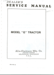
General
A typical PC-system and its interfaces are shown in figure 1 below.
22
L
conditions
information to be provided by the manufacturer
The manufacturer
2.4
for any mechanical
advancedfunctions
WIEC 1131-2(1992)
-
I
7
Main processing unit
Remote VO station
Programmable
controller
system
(PC - system)
t-3
4-L
le
4-
-i
W’
Digital 6 analog
outputs
mmocy
--i
(ies)
3rd Party devices
@onlputers.
printers,
1etminals)
and
-i
Processing
Unit@)
1
G
--I
-I
-
r
--I
-I
i-4
Limit of tha scope of this standard
Mains
P-
WPPfY
Pmtective earthiw
Functional eardring
-1
lnteffacad davic8s and signals
,t
A0
Interface for remote VO stations.
-
Interface for peripherals
(permanently/non
permanently)
C I
Interface for digital and analog input signals.
D =
Interface for digital and analog ouput~signals.
E
Serial or parallel interfaces for data communication
devices.
=
F =
Interface for incoming power supply.
G=
Interface for protective
installed.
with third party
earthing.
H = Optional interface for functionnal earthing.
EC
Figure 1 - Typical interface diagram of a programmable controller -system
23
9s492
IS/lEC 113%2(1992)
3.2
A.C. and d.c. power supply
3,2.1
Incoming power supply
3.2.1.1
Rated values and operating ranges
Incoming power supplies to the PC-system
shall be as shown in table 7 below:
Andy to the externally
powered I/O modules
Table 7 - Rated values and operating ranges of incoming power supply
Voltage
Rated
(U,)
24 V d.c.
Tolerance
Min. / Max.
Rated
(F,)
Recommended
Tolerance
Min. I Max.
-15%1+20%
.d
48V”d.c.
24 V a.c.
Frequency
-15%/+10%
48 V a.c.
56Hzor60~2
use: R
Notes
Power
supply
110
signals
5
R
R
1
R
R
1.2
-5%1+5%
3
id
id
id
12OVac.
id
id
id
R
R
3.4
230 V a.c.
id
id
id
R
R
3,4
400 V a.c.
id
id
id
R
3-
3t4.6
NOTES
1
In addition to the voltage tolerances, a total a.c. component having a peak value of 5 % of the
rated voltage is allowed. The absolute limits are 30119.2 V d.c. for 24 V d.c. and 60/38,4~ V d.c. for
48 V d.c.
2
See item 5 of 3.3.1.2 if type 2 digital inputs are-likely to be used.
3
A.C. voltage is~in terms of the total r.m.s. voltage values measured at the point of entry to the
equipment.
Total r.m.s. content of true harmonics (integral multiple of nominal~ frequency) less than 10 times
nominal frequency may reach 10 % of the total voltage. Harmonic and other frequency content for
higher frequencies may reach 2 % of the total voltage. However, to provide constant comparative
results, the equipment shall be tested at the third harmonic only (10 % at 0 and at 180” phase
angle).
The total contenf of harmonics of the power supply to the PC-system may be affected when the
energy source output impedance is relatively high with regard to the input impedance of the
PC-system power supply; sizing a dedicated power source such as an inverter for a PC-system may
require an agreement between the user and the manufacturer. Use of line~conditioner should be
considered See IEC 1131-4.
4
These-rated voltages are derived from IEC 38.
5
For ineoming voltages other than those given in the table such as 100 V a.c., 110 V a.c..
200 V a.c., 240 V a.c., 380 V a.c. or 110 V d.c., 125 V d.c.. the tolerances given in the table and
notes 1 and 3 apply. These voltage tolerances shall be used to calculate the input limits of 3.3.1.2.
using the equations in annex 0.
I’
6
Three-phase
supply.
7
For power supplies for analog I/OS, see item 5 of 3.4.1.2.3 and item 3 of 3.4.2.2.3.
24
IS/IEC 1131-2 (1692)
3.2.1.2
Voltage drops and interruptions
1) For short disturbances of the supply as defined in table 8 below, the PC-system
(including RIO& and non-permanently
installed peripherals, see 3.7) shall maintain
normal operation.
2) For longer interruptions of the supply(ies), the PC-system shall either maintain
normal operation or go to a predefined state and have a clearly specified behavior until
normal operation is resumed.
NOTE - Outputs and fast responding
-power supply variations.
inputs energized
Tabte 8 - Normal service conditions:
-by the same
Severity
Seventy
level PSI
5 1 ms
level PS2
will respond
to these
Voltage drops and interruptions
Interruption
time
D.C. supply
supply(ies)
5 10ms
Time interval
between drops
Low voltage
21s
21s
Any voltage
under lower
operational
limit
A.C. supply
5 06
period
21s
Urn,”
(note
2)
(note 1)
NOTES
1
Any arbitrary
_2
U,+, is the
3
PSl applies to PC-systems
PS2 applies to PC-systems
3.2.1.3
phase angle - (see test procedure
U, at minimum tolerance
Non-periodic
in 6.3.7.2).
in table 7.
supplied by battery.
energized from rectified a.c. supplies and/or long d.c. lines.
overvoltages
See 2.1.2.4.
3.2.2
Memory back-up
Power back-up for volatile memories shall be capable of maintaining stored information for
at least 300 h under normal service conditions, and 1 000 h at a temperature not greater
than 25 “C when the energy source is at rated capacity. (For power back-up needing
replacement, the rated capacity is the value used to designate the procedure and time
interval for replacement.)
It shall be possible to change or refresh power back-up without loss of data in the backedup portions of memory. (See also 2.3, 3.6.3 and 4.11.)
lf a memory back-up
provided.
battery
is provided,
a warning
25
of low battery
voltage
shall
be
lS/fEC 1131-2 (1992)
3.2.3
Information
to be provided by the manufacturer
In addition to the requirements
following mformation:
stated in clause 5, the manufacturer
shall provide the_
1) data to allow selection of a suitable power distribution network to provide specified
voltage at each power utilization point. This information includes peak inrush, repetitive
peak and steady-state r.m.s input currents under full load conditions;
2) external terminal identification
for power supply interfaces;
3) typical example(s) for power supply system(s);
4) special supply installation requirements, if any, for PC-systems energized through
multiple power supplies or supply voltages and frequencies not included in 3.2.1 .l;
5) the effect of the following incorrect connections
-
reverse polarity;
-
improper voltage level and/or frequency;
-
improper lead connection;
6) complete
sequences;
information
on
PC-system
of power to the supply(ies):
behaviour
for
typic-al
power
up/down
7) data to allow evaluation of the maximum values of interruption time which do not
affect the normals operation of .any PC-system configuration; PS class (PS-1 or PS-2) of
d.c. supplied devices;
8) memory back-up time with respect to temperature
and maintenance
requirements;
9) recommended time interval between replacement of energy sources,
and recommended procedure and subsequent effects on the PC-system.
26
if applicable,
IS/IEC 1131-2 (1992)
3.3
Digital I/OS
The following figure 2 gives an illustration
Current
of definitions
sinking
r----
~PC INPUT
of some I/O parameters.
Current
---------1
i,
INPUT
I
I
COMMON
(REFERENCE)
I
I
1
sourcing
PC OUTPUT
I
I
E
E
-_
IEC
c: output
- Mechanical
or static contact (e.g. dry relay contact, triac, transistor
orequivalent).
E: Earthings
- The earth shown are optional.
- Earthings is dependent on national
regulations
and/or application
needs.
2: tnput
- Input impedance.
PS:
External
power supplies.
NOTE - Some applications
may use only one PS common to inputs, outputs, and PC-system.
Figure 2 - I/O parameters
Digital I/OS shall comply with the following requirements:
1) the PC-shall be provided with at least one type of input interface and -one type of
output interface among those defined respectively in 3.3.1, 3.3.2 and 3.3.3;
2) digital inputs shall comply with the requirements of the standard voltage ratings
given in 3.3.1. Non-standard voltage digital inputs should be in accordance with the
design equation given in annex B;
3) digital outputs shall comply with the requirements
3.3.2.1 for a.c. or 3.3.3.1 for d.c.;
of the standard
ratings given in
4) it shall be possible to interconnect inputs and outputs by means of a correct
selection of the above digital I/OS, resulting in proper PC-system operation. (Additional
external load shaltbe specified by the manufacturer if necessary);
5) it shall be possible to feed multi-circuit
a.c. input modules from different phases
and the modules shall then comply with the maximum voltage difference likely to occur
between phases, or the user manual shall include a note indicating that all channels
must be fed from the same phase;
27
955f9l
WIEC 1131-2(1992)
6) if a multi-channel
a.~. circuit is intended for multi-phase use the circuit shall comply
with the clearance and creepage distance requirements
and the dielectric
test
corresponding to the voltage between phases.
NOTES
1
Current sourcing inputs and current~sinking outputs which may be required for certain applications are
not covered in this standard. Special cars should be exercised in their use. (Where positive logic, current
sinking inputs and current sourcing outputs are used, any short-circuit to the reference potential and wirebreakage are interpreted by the inputs and loads as the ‘off state’; on the other hand, for current sourcing
inputs and current sinking outputs, earth faults are interpreted as the ‘on state’.)~(See figure 2).
2
A PC-system may be offered with interfaces which are not covered in this standard, i.e., interfaces for
TTL and CMOS circuits, etc. In such a case, the manufacturer’s data shall give all relevant information to
the user.
3.3.1
3.3.1.1
Digiial inputs (current sinking)
Terminology (WI operation regions)
Figure 3 below represents graphically the limits and operating
herein to characterize current sinking digital input circuits.
ranges which are used
Operating region consists of “on region”, “transition region” and “off region”. It is necessary to exceed both UT min. and IT min. to leave the “off region”, and to exceed IH min.
before UH mkt. to enter the “on region”: all input U/I curves shall remain within these
boundary conditions. The region below zero volts is a valid part of the “off region” for dc.
inputs only.
The figure also presents a graphical illustration of the method- explained in 3.3.1.5 for
determination of compatibility between a 2-wire proximity switch (curve I: worst case at
state 1, curve II: worst case at state 0), and a given input impedance curve (curve Ill).
28
lS/tEC 1131-2 (1992)
IEC 9S8?92
UH max. and UH min. are the voltage limits for the ON conditions
(state 1)
IH max. and UH min. are the current limits for the ON conditions (state 1)
UTmax. and UTmin.
ITmax. and ITmin.
are the voltage limits for the transition
state (ON or OFF)
are the current limits for the transition state (ON or OFF)
UL max. and UL min. are the voltage limits for the OFF conditions
(state 0)
IL max. and IL min. are the current limits for the OFF conditions (state 0)
UL max. equals UL min. to Kmin.
and equals UTmin. above ITmin.
Ue, Ue max. and Ue min. are the rated voltage and its limits for the external power supply voltage
I. II. Ill. (a), (b). (c), A. 6 relate to the example described in 3.3.1.5.
Figure 3 - U/I operation regions of current sinking inputs
3.3.1.2
Standard operating ranges for digital inputs (current sinking)
Current sinking
table 9.
digital
inputs shall operate
within
29
the limits presented
in the foIlWing
1131-2 (1992)
lS/fEC
Table 9 - Standard operating ranges for digital inputs (current sinking)
ND: Not defined
Rated
fre-
Rated
voltage
Type 1 limits (note 7)
quency
‘i:
F
n
limit
Hz
“e
U V d.c..
-
46 V d.c.
-
State 0
Transition
Type 2 limits (note~ir)
State 1
UL
V
IL
mA
UT
V
IT
mA
Max.
Min.
156
-3
15
ND
15
5
15
0.5
30
15
Max.
34/10
-6
15
ND
34
10
15
0,5
15
14
5
Min.
1415
00
UH
V
IH
mA
State 0
Transition
State 1
UH
V
Notes
UL
V
IL.
mA
UT
V
IT
mA
IH
mA
15
2
11/5
-3
36
ND
11
5
30
2
30
11
36
6
60
34
15
2
3fYlO.
-6
30
30
30
60
30
ND
10
2
36
6
15
1
27
14
15
2
1015
0
30
0
10
5
39
4
27
10
39
6
183
1,3
24 V 8.c.
50/69
Max.
Min.
b6 Va.c.
50&O
Max.
Min.
34/10
0
15
0
34
10
15
1
53
34
15
2
29llO
0
30
0
29
10
30
4
53
29
36
6
109 V a.c. .50/66
1~10V a.c.
120 V a.c.
Max.
79l20
15
79
15
1,l un
15
74&O
30
74
36
1.1 un
30
Min.
0
0
20
1
79
2
0
0
20
4
74
6
KtOVac.
230
V ac. 5666
Max. 164I46
15
164
15~ 1.1 un
15
30
159
36
1,l un
30
240 V a.c.
Min.
0
0
40
164
3
0
46
5
159
7
2
159140
0
1.24.5
lq2.4
l,3,4,6
l,3,4,6
NOTES
1
All logic signals are in positive logic. Open inputs shall be interpreted as state 0 signal. Compatibility with
P-wire proximity switches according to IEC 947-5-2 is possible with type 2 (see also note 3). See annex B for
equations and assumptions used in developing values in this table and for additional comments.
2
The given voltage limits include all alternating voltage components.
3
Static switches may affect the total r.m.s. content of true harmonics of the input signals and therefore affect
the compatibility of the input interface with proximity switches, especially for type 2, 24 V a.c. See 3.2.1.1 for
requirements.
4
Recommended for common usage and future designs.
5
The minimum external power supply voltage for type 2, 24 V d.c. inputs connected to two-wire proximity
switches should be higher than 20 V d.c. or UH min. lower than 11 V to allow sufficient safety margin.
6
As allowed by the current technology, and to encourage the design of single input modules compatible with
all commonly used rated voltages, limits are absolute and independent of rated voltage (except UH max.) and
based on equations given in annex B and respectively 100 V a.c. and 200 V a.c.
7
See definitions in 1.4.25.
30
IS/IEC 1131-2 (1992)
3.3.1.3
Additional
requirements
Each input channel shall be provided with a lamp or equivalent
state 1 condition when the indicator is energized.
3.3.1.4
Information
of clause 5, the manufacturer
curve over the full-operating
shall provide the following
1)
volt-ampere
2)
digital input delay time (TID) for 0 to 1 and 1 to 0 transitions;
3)
existence of common points between channels;
4)
effect of incorrect input terminal connection;
isolation potentials
5)
service conditions;
range, with tolerances
or equivalent;
between channel and bus and between channels under normal
9)
type of input (type 1 or type 2);
7)
monitoring point and binary state of visual indicator;
3)
effects when withdrawing/inserting
9)
additional external load when interconnecting
of signal evaluation
11) recommended cable
magnetic compatibility;
12)
terminal arrangements;
13)
typical example(s)
input module under power;
inputs and outputs, if needed;
(for example static/dynamic
and cord lengths
depending
evaluation,
interrupt
on cable type and electro-
of external connections.
Method for determination
3.3.1.5
the
to be provided by the manufacturer
tn addition to the requirements
information:
10) explanation
release, etc.);
means to indicate
of compatibility
with proximity switches
For a given proximity switch, the following characteristics
shall be identified:
0 when at state 1:
a)
‘drop:
maximum voltage drop at state 1
b, ‘hold: minimum output current load at state 1
I: worst case output curve at state 1
ii) when at state 0:
c) Ileak: maximum output current at state 0
II: worst case output curve at state 0.
A given proximity switch shall be compatible
impedance curve of the input) if:
with a given
-
its curves I and II do not enter the “transition
-
its Ihold is smaller than IH min.
31
region”, and
standard
input
(curve
Ill:
IS/lEC 1131-2 (1992)
Worst case steady states 0 and 1 shall be respectively
III with II and I).
_ This method may be used for any other type of static switch, such as outputs,
NOTE
3.3.2
at points A and B (at crossings
oft
etc.
Current sourcing digital outputs for alternating currents
Rated values and operating ranges (a.c. r.m.s.)
3.3.2.1
Digital a.c. outputs shall comply with th6 ratings given in the following table 10, at the output voltage(s) stated by the manufacturer according to 3.2.1.1 and IEC 947-5-1, utilization
category AC-1 5. See item 9 of 3.3.2.3, for other utilization categories.
Table 10 - Rated values and operating ranges for current sourcing digital a.c. outputs
tated current
(state
1)
le (A)
0,25
0,5
1
2
Notes
1, 2
:urrent range for state 1
continuous at max. voltage)
Min. (mA)
Max. (A)
10 [5]~
0,28
20
0.55
100
100
l,l
2,2
‘oltage drop (state 1)
Non-protected
output
Protected and short-circuit
Max. (V)
Max. (V)
3
5
3
5
3
5
3
5
5 I31
2,5
10
10
10
2.5
2.5
2,5
.eakage
current
(state
1
proof
1
0)
. Solid state outputs
. Electromechanical
outputs
Max. (mA)
Max. (mA)
?epetition
overload
Operating
cycles/min
rate for temporary
- Solid state outputs
- Relay based outputs
Min.
4
60
6
Min.
2. 3
30
6
30
6
30’
6
NOTES
1
R.M.S.
currents
and voltages.
Figures between [ ] apply to module not equipped
with
2
pressors. All other values apply to modules with suppression..
Leakage current for solid state
3
loads to drive type 2 inputs.
outputs
greater
RC network
than 3 mA imply
or equivalent
the use of additional
surge
sup-
external
Typical waveform
for temporary
overloads
(‘normal
conditions
of use’) are shown in figure 4.
4
The test method given in IEC 947-5-l
applies to solid state outputs for ‘normal conditions
of USB’
except that the repetition
rate shall be as given in the table. For ‘abnormal
conditions
of use”, the
requirements
given
in IEC 947-5-l
apply.
IS/EC
113%2(1992)
Currents (A)
: 2 cycles at Fn (Fn = rated line frequency)
: “ON” time
t2
Q-12 _:“0FF”time (“OFF’ time = “ON” time)
11
t3
:~Operation time
l
Relay OUTPUT
13 110
l
Salid state OUTPUT
0,25 A
t3=ls
s
1 to5A
t3=2s
___
43
0
time (s)
t3
t2
t1
&c
Figure 4 - Temporary overload waveform for digital a.c. outputs
NOTE - In IEC 947-5-1,
3.3.2.2
ths curve shown in figure 4 is named ‘AC-15,
normal conditions
of use*.
Additional requirements
Output indica tars
Each output channel shall be provided with a lamp or equivalent
output state 1 condition when the indicator is energized.
means to indicate the
Protected outputs
For outputs stated by the manufacturer
to be protected:
1) the output shall either withstand and/or the associated protective device shall
operate to protect the output for all steady state values of output current greater than
1 ,l times the rated value;
2) after resetting or replacement of the protective device alone, as applicable,
system shall return to normal operation;
the PC-
3) during any overload, there shall be no evidence of risk of fire or electrical shock,
and immediately after any overload, the maximum temperature rise of the I/O insulation
shall not exceed the value specified in 4.4.2.
Optional restart capabilities
may be selected among the three following types:
1) automated
restart protected output:
recovers after the overload is removed;
ii) controlled restart protected
signals (e.g. for remote control);
output:
a protected
a protected
output
output
which
which
automatically
is reset through
-iii) manual restart protected output: a protected outp_ut which implies a human action
to recover. (the protection may be fuses, electronic interlocks, etc.).
See test procedure in 6.3.8.3.2.
33
9%%??
lS/lEC 1131-2 (1992)
NOTES
Operation
1
module.
under overload
condition
for an extended
2
The protected outputs will not necessarily
provide that protection when it is needed.
period
protect the external
of time may affect
wiring.
operating
life of the
It is the user’s responsibility
to
Short-circuit proof outputs
For outputs stated by the manufacturer
to be short-circuit
proof:
4) For all output currents greater than le max. and up to 2 times the rated value le, the
output shall operate and withstand temporary overload(s)_. Such temporary overload(s)
shall be specified by the manufacturer.
5) For all output currents prospectively above 20 times thee rated value, the protective
device shall operate. After resetting or replacement of the protective device alone, the
PC-system shall return to normal operation.
6) For output currents in the range of 2 times to 20 times I,, or for temporary overload(s) beyond the limits specified by the manufacturer (item 1 above), the module may
require repair or replacement.
7) During an overload of 2 le applied for 5 min. there shall be no evidence of risk of
fire or electrical shock and immediately after the overload, the maximum temperature
rise of the I/O insulation shall not exceed the value specified in 4.4.2.
See test procedure in 6.3.8.3.2.
Not-protected
outputs
For outputs stated by the manufacturer to be not-protected, their operation with the protective devices provided or specified by the manufacturer shall meet all the requirements
stated for the short-circuit proof outputs.
Electromechanical
relay outputs
Electromechanical
relay outputs shall be capable of performing at least 0,3 million operations at the AC-15 utilization category (durability class 0.3) according to IEC 947-S-l.
NOTE - The type test is not required if the relay components
ments of IEC 947-5- 1.
3.3.2.3
Information
have been shown to comply with the require-
to be provided by the manufacturer
In addition to the requirements oft clause 5, the manufacturer
information with respect to digital outputs for a.c. operation:
34
shall provide the following
IS/IEC 1131-2 (1992)
1)
type of protection (i.e. protected, short-circuit
proof, not-protected
output) and:
- for protected outputs: operating characteristics
beyond 1 .l & including the
current(s) level(s) at which the protecting device energizes, the current behaviour
beyond, and the time(s) involved;
- for short-circuit proof outputs:
tective device as required;
t
- for not-protected
user, as required;
information
outputs: specification
for replacement
or resetting
the pro-
for protective device to be provided by the
output delay time (TQD) and output transfer times (TQT) for state 0 to state 1 and
2)
state 1 to state 0 transitions;
commutation
3)
crossing;
characteristics
and turn-on
voltage
4)
existence of common points between channels;
5)
terminal arrangements;
6)
typical example(s) of external connections;
with respect
to zero voltage
number and type of outputs (e.g. NO/NC contacts, solid state, individually
7)
channels, etc.) ;
isolated
for electromechanical
relays, the rated current and voltage of the contacts for
utilization category AC-15 and durability class according to IEC 947-5-l and their
mechanical life;
8)
output ratings for the other utilization
9)
loads such as incandescent lamps:
10)
total output current for multichannel
categories
(AC-12, AC-13, AC-14) or other
modules (see definition in 1.4) ;
11) characteristics of suppressor networks incorporated
voltage peaks due to inductive kickback;
12)
type of external protective networks, if required;
13)
effects of incorrect output terminal connection;
14) insulation/potentials
and between circuits;
under normal service
into the output circuit against
conditions
between
circuits
and bus
15)
monitoring points of visual indicators in the channel (e.g. MPU side/load side);
16)
recommended procedures for changing output modules;
17) output behaviour during interruptions of MPU control,
ruptions and power up/down sequences (see also 3.6) ;
18)
way of operation (i.e. latching/non-latching
19)
effects of multiple overloads on multi-circuit
3.3.3
3.3.3.1
voltage drops and inter-
type);
modules.
Current sourcing digital oufpurs for direct currenf
Rated values and operating ranges
Digital outputs shall comply with the ratings given in the following table 11, at the output
voltage(s) stated by the manufacturer according to 3.2.1.1 and with IEC 947-5-l for
utilization category DC-l 3.
35
lS/lEC 1131-2 (1992)
Table 11 - Rated values and operating ranges for current sourcing digital d.c. outputs
Rated current
(state 1)
ie (A)
Current range for stage 1 at
maximum voltage (continuous)
Voltage drop
Not-protected output,
protected and short-circuit
proof
0,l
0,25
0,s
1
2
2.4
Max. (A)
0,12
0,3
0.5
1,2
Max. (V)
3
3
3
3
3
3
3
3
0,4
1
2
2
Leakage current (state 0)
Max. (A)
Temporary overload
Max. (A)
According to manufacturer’s
Notes
~3
3
1
4
2
specifications
NOTES
1
For 1 A~and 2 A rated currents, if reverse polarity protection is provided, a 5 V drop is allowed.
This makes. the output incompatible with a type 1 input of the same voltage rating.
2
The resulting compatibilities
load, are as follows:
.
Rated output current le (A):
Type 1:
Type 2:
With adequate additional
type 2 d.c. inputs.
3.3.3.2
between d.c. outputs and d.c. inputs, without
O,f
yes
yes
0,25
no
0.5
no
yes
yes
1
no
yes
external load, all d.c. outputs may become compatible
additional
2
no
no
with all type 1 and
Additional requirements
Other requirements
3.3.2.2, except:
are #w same as for current
sourcing
outputs for a.c. as defined in
-
for protected outputs: the limit is 1,2 le instead 1 ,l 1,
-
for electromechanical~ relay outputs: AC-1 5 is replaced by DC-l 3.
3.3.3.3
external
lnformafion
to be provided- by the manufacturer
Information to be provided by the manufacturer for digital outputs for d.c. shall be the
same as for digital outputs for a.c., as defined in 3.3.2.3, except ‘that the specification of
commutation for zero voltage crossing does not apply, and AC-12, AC-13, AC-14 are
replaced by DC-12 and DC-13.
J6
KMEC lt31-2 (1992)
3.4
3.4.1
3.4.1.1
Analog LOS
Analog inputs
Rated values and impedance
limits
Rated w&s
of signal range and impedance
specified in the fo[kwing t&ie 12.
Table 12-
Rated values and impedance
Signal range
-Iov,
for analog inputs to PC-systems shall be as
Input impedance limits
+Iov
+5-V
4 mA,
20 mA
Notes
219U
Ov, +1OV
Iv.
limits for anaiog inputs
210tKl
25kl-1
S300Q
t
o n-A, 20rnA
s 300n
t
NGTE
1
Not recorn,mended for future desi~ns.
Anaiog inputs may be designed to be compatible with standard therrrmcoupies or standard
resistive temperature devices (RTDs) such as 100 Q Pt sensors. Thermocouple analq
inputs shaii provide a built-in coid-junction compensation.
37
IS/IEC
1131-2(1992)
3.4.1.2
Information
to be provided
Table
3.4.1.2.1
Static
by the manufacturer
13 - Analog
inputs:
information
to be provided
Units and examples
characteristics
1)
Input impedance
2)
Analog input error
- Maximum error at 25 “C
- Temperature
coefficient
in signal
range
R
3)
4)
5)
6)
Maximum error over full temperature
range
Digital resolution
Data format returned to the application
program
Value of LSB (least significant
bit)
7)
8)
Maximum permanent
allowed overload (no damage)
Digital output reading under overload condition
9)
10)
Type of input.,
Common mode characteristic
11)
For other inputs
f % of full scale
f % of full scale/K
f % of full scale
Number of bits
Binary, BCD, etc.
mV. mA
V, mA
e.g. flag
e.g. differential
CMRR-dB,
CMV-V
(d.c., 50 Hz. 60 Hz) if applicable
(thermocouples,
RTD, etc.)
- type(s) of sensor(s)
- measurement
range(s)
- linearization
method
J. K, T, etc.: Pt 100. etc.
Min. “C lo Max. “C
Internal or
user-provided
0
3.4.i.2.2
1)
2)
3)
4)
5)
Dynamic
Units and examples
characteristics
Total input system transfer time (TAID + TAIT)
Sample duration time (including settling time)
Sample repetition time
Input filter characteristics
-order
- transition frequency
Maximum temporary deviation
electrical noise test
3.4.1.2.3
General
First, second,
during
each specified
f. % of full scale
Units and examples
characteristics
Dual slope, S:A..
etc.
Trig, self-scan,
etc.
RC. opto-isolator.
MOVs, etc.
Conversion
method
2)
Operating
3)
Type of protection
4)
Isolation
5)
between channel and a) bus, b) other channels,
c) power supply(ies)
interface(s)
External power supply data, if required
modes
potentials
under normal
service
Common points between channels if any
Type, length of cable, installation
rules
recommended
lo provide noise immunity
8)
9)
Calibration
or verification
Terminal arrangements
10)
11)
Typical example(s)
of external connections
Effect of incorrect input terminal connection
1)
2)
3)
to maintain
s
conditions
6)
7)
Miscellaneous
etc.
Hz
1)
3.4.1.2.4
ms
ms
ms
V
Technical
Twisted
years
Units and examples
characteristics
4)
Monotonicify
with no missing codes
Crosstalk between channels at d.c., 50 Hz and 60 Hz
Non-linearity
Repeatability
at fixed temperature
after specified stabilization
5)
Life time of electromagnetic
relay multiplexors.
pair, 50 m max.
Month.
rated accuracy
data
if applicable
38
Yes, no
dB
time
% of full scale
% of full scale
Number
of cycles,
of hours
IS/IEC 1131-2 (1992)
3.4.2
3.4.2.1
Analog outputs
Rated values and impedance limits
Rated values of signals range and load impedance for analog outputs of PCs shall be as
specified in the following table 14:
Table 14 - Rated values and.impedance
limits for analog outputs
Load impedance
Signal range
limits
Notes
-10 v +lO v
1
O~V +lO v
1
+lV
+5v
1
4nlA.
2omA
2
OmA,
2omA
2.3
NOTES
1
Voltage
circuit.
analog
2
Current
circuit.
analog
3
3.4.2.2
outputs shall withstand
Not~recommended
Information
outputs
shall withstand
any overload
any overload
down to short
up to open
for future designs.
to be provided by the manufacturer
In addition to the requirements
infoimation:
of clause 5, the manufacturer
39
shall provide the following
IS/IEC 1131-2 (1992)
Table 15 - Analog outputs: information to be provided
3.4.2.2.1
Static
Units and examples
characteristics
Output
Analog
3)
4)
5)
- maximum error at 25 “C
-temperature
coefficient
Maximum error over full temperature
Digital resolution
Data format in application
program
6)
Value
3.4.2.2.2
I)
2)
3)
0)
impedance
in signal
output error
R
1)
2)
of LSB (least
Dynamic
range
significant
range
Binary, BCD. etc.
mV, mA
bit)
Units and examples
characteristics
Total output system transfer
time (TAQD
Settling time for full range change
Overshoot
Maximum temporary
deviation
noise tests and test conditions
3.4.2.2.3
General
f % of~foll scale
& % of full scale/K
f % of full scale
Number of bits
during
ms
ms
% of full scale
f % of full scale
+ TAQT)
electrical
Units and examples
characteristics
Opto-isolators,
1)
2)
Type of protection
Isolation potentials
3)
4)
and a) bus, b) other channels, c) power supply(ies)
interface(s)
External power supply data if required
For current outputs with external supply, the maximum and minimum
voltage drop across the output terminals in the full output range
5)
6)
7)
6)
9)
under normal
service
conditions
between
Type, length of cable, installation
rules recommended
to provide noise immunity
Calibration
or verification
to maintain rated accuracy
Terminal arrangements
Common points between channels if any
Allowed type(s) of loads
10)
Maximum
11)
12)
13)
14)
Maximum induetive load (for current outputs)
Typical example(s)
of external connections
Output response at power up and power down
Effect of incorrect output terminal connection
3.4.2.2.4
capacitive
Miscellaneous
load (for voltage
etc.
channel
V
Technical
data
V
Twisted pair, 50 m max.
Months, years
Floating,
grounded
outputs)
PF
ml-f
Units and examples
characteristics
1)
2)
3)
4)
Monotonicity
Crosstalk between channels at dc.. 50 Hz and 60 Hz
Non-linearity
Repeatability
at fixed temperature
after specified stabilization
5)
Output
ripple
40
time
Yes,
dB
% of full
% of full
% of full
no
scale
scale
scale
WIEC 1131-2 (1992)
3.5
Communication
3.5.1
interfaces
General requirements
The configuration which shall be tested according to clause 6 of this standard shall be
equipped with communication interface modules where applicable and with communication
links specified by the manufacturer.
Communication
interface modules are subject to all general requirements
relating to
service conditions, mechanical construction, safety, markings, etc. (see in particular 2.1,
3.8, 3.9 and clause 4).
3.5.2
Information
to be provided by the manufacturer
tf the manufacturer provides communication interfaces to other fhan his own equipment,
he shall provide the necessary information for correct operation. This information shall
include, but not be limited to, type of link, baud rates, energization of the Kline, type of
cable to be used, isolation characteristics, protocols, character encoding, frame encoding,
etc.
3.6
Main processing unit(s) and memory(ies)
of the PC-system
NOTE - This subclause should be read in conjunction
(respectively: MOSS and peripherals).
3.6.1
with IEC 1131-l
and with 3.7 and 3.8 of this part
General
See figure 1 in 3.1, and annex A for the definition and illustration of PC-system,
processing unit (MPU), main memory and other terms used in this subclause.
3.6.2
main
Requirements
Main processing unit(s) and memory(ies) are part of the permanent PC-installation
and
therefore tested accordingly. They are subject to all general requirements relating to
service conditions, mechanical construction, safety, markings, etc. (see in particular 2.1,
3.8, 3.9, 3.11 and clause 4)
3.6.3
Information to be provided by the manufacturer
-1)
organization,
capacity of program memory;
2)
organization,
capacity of data memory and number of bits per word;
3)
memory type(s) (i.e. CMOS-EPROM,
4)
memory back-up functionality
etc.) available;
and service requirements
if any;
data, constraints and procedures to determine a desired configuration
(racks,
5)
cables, bus expanders, power supply unit, maximum number of I/OS per t_ype, maximum
number of I/O modules, etc.)
description of the programming tanguages supported by the PC-System (combina6)
tion of the PADT and the main processing unit(s);
to what extent the languages defined in IEC 1131-3 are supported, including
7)
differences if any (objects, instructions, semantic and syntactic rules, etc.);
41
the
lS/iEC 1131-2 (1992)
8) calculation methods to determine_ every memory utilization (user’s application
program and data, firmware program and data where applicable)
and average,
minimum and maximum value of every relevant time (scan time(s), system response
time(s), transfer time(s), execution time(s));
mechanisms in which I/OS are processed (i.e. use of l/O image registers perio9)
dically refreshed by the system, immediate “get/put” type instructions,
interrupt and
event-driven programs, etc.) and their effect on the following subjects:
- system response time(s) ;
- restart capabilities
1
(i.e. cold, warm, hot restart) ;
1~0) detailed times for inputs, outputs, processing,
etc.
11) effect of non-permanently installed peripherals on every relevant time (see item 8
above) when they are plugged/unplugged,
connected/disconnected
to their PC-system
interface;
12) PC-system status information concerning cold, warm and hot restarts if applicable.
Description and usage of programmable timers usable to determine the ,processdependent_ difference between~ warm and hot restart;
l-3)
3.7
test and diagnostic functions implemented
Remote input/output
(see 3.11) .
stations (RIOSs)
MOSS are part of the permanent PC-installation and therefore to be tested accordingly.
However, for ease of testing, isolated RlOSs may be tested separately where appropriate.
3.7.1
Requirements
1) Requirements for voltage drops and interruption
to RlOSs (see 3.2.1.2).
of the power supply(ies)
fully apply
2) In case of loss of communication with the MPU application program, RlOSs shall be
able to fix the states of their outputs to specified values, within specified delays and
without passing through unspecified
states and be capable of providing a fault
indication signal.
3)~ The MPU system shall provide the user’s application
mation on current status of RIOSs.
3.7.2
Information
infor-
to be provided by the manufacturer
In addition to the requirements
information:
1) specifications
the communication
of clause 5, the manufacturer
for the selection
link;
specifications
for proper
2)
selection of energy source(s));
3)
program with relevant
type of l/O communication
shall provide the following
of adequate cables and other devices needed for
installation
of the
whole
system
network (point to point, star, multidrop,
42
(including
prope-r
ring, etc.) ;
IS/IEC 1131-2 (1992)
principles, procedures and transmission speeds used on the communication link
4)
and their capability to transfer data from and to the RlOSs with respect to error
coding/detection
and to the delays of transmission in the best, most likely and worst
cases;
effect on transfer time(s) introduced to provide remote input information and
5)
RlOSs status to the user’s application program and to transmit its logical decisions to
remote outputs;
6)
specified values and delays according to 3.7.1;
configuration related data: maximum number of RlOSs in one single
7)
configuration, min./max. size of each;
PC-system
which I/O modules of the total I/O system ~may not be used in RlOSs and/or which
8)
of their functions are altered if any;
9)
type, architecture
10)
modems/repeaters
11)
terminating
and characteristics
if applicable.
of redundancy
if provided;
Maximum distance with or without repeaters;
devices if required;
12) physical characteristics of the communication interface including isolation characteristics, maximum acceptable common mode voltage, built-in short-circuit protections,
etc.;
13)
type of standard link interface (i.e. RS 232, RS 422, RS 485, RS 511, etc.);
14)
functional
and safety earthing specifications;
15) procedures for making/breaking
PC-system (e.g. “on line”) .
3.8
Peripherals
3.8.1
logical and physical
connection
of a RIOS to a
(PADTs, TEs, MMls)
Requirements
1) Peripherals which are not a permanent part of the PC-system shall cause no
malfunction of the system when making or breaking communication with an operating
system.
2) Connectors for the peripherals shall be polarized to prevent improper connection,
the PC-system shall be-so designed that no malfunction occurs.
or
3) The system consisting of the peripheral and the PC-system shall be designed
ensure that the edited program executing in the PC-system is functionalfy identical
1
the edited program displayed on the peripheral.
to
to
4) If on-line modification of the application program and/or the modes of operation of
the PC-system by a peripheral is possible (i.e. when the PC-system is in active control
of a machine or industrial process), then:
- the peripheral shall automatically give clear warnings equivalent to “during online modification, program display may differ from application program, control of
the machine/process may be interrupted during . . . ms, etc.“. as applicable,
43
IWIEC 1131-2 (1992)
- the peripheral shall ask similar meaning words to “do you really want to carry out
this acfion?” and execute the command only after a positive reply has been given by
the operator,
- it shall be possible to upload the new application program to the manufacturer’s
supplied data media and verify, on line, that the record is functionally equivalent to
it,
- means shall be provided
(hardware or software).
3.8.2
to minimize
unauthorized
use of these functionalities
Information to be provided by the manufacturer
1) Clear warnings and precautions to be observed when using functions enabling
alteration of control conditions such as PC-system status modification, changing of data
or programs in the memory, forcing input or output signal, etc.
2) Usability of peripherals
at RIOSs.
3) Service conditions for peripherals which are intended for use in an environment less
severe than stated in clause 2 (such peripherals may need to begremotely connected to
the rest of the PC-system through communication lines).
3.9
Noise immunity and emitted noise
3.9.1
Electrical noise immunity requirements
As receiving equipment,
radiated electromagnetic
which shall be followed
withstandable levels are
PC-systems are affected by interferences from conducted noise,
fields, and electrostatic discharges_ General rules of installation
to limit coupling factors and consequently interfering voltages at
noted in IEC 1131-4.
The PC-system shall comply with’the requirements
in table 16.
NOTES
Conditions of use may require immunity to higher levels of electrical noise than the minimum given
1
above. The manufacturer may select such higher values given in annex C. These higher levels shall be
stated by the manufacturer and the tests conducted according to these levels.
2
The reference
document
for detailed
tutorial and consideration
44
is IEC 801.
lS/lEC 1131-2 (1992)
Electrical noise immunity requirements for PC-system
and stand-alone peripherals (notes 1 and 2)
Table 16 -
Electrical
Electrical
noise tests
Maximum
%adioelectromagnetic
>onducted
severity
levels
Digital I/OS
ue c 24 v
surge
energy
Minimum source
impedance
Electrostatic discharge
- For level RH-1: ES09
- For level RH-2: ESD-4
noise
All power
supplies
Digital I/OS
ue z? 24 v
Notes
Analog, communication I/OS
150 pF1150 Q
3, 4
8 kV
15~kV
8 kV
l5kV
8 kV
15 kV
10 V/m
10 V/m
10 V/m
3
4 mJ/spike at 2 kV
on 50 11
2 kV
1 kV
0,25 kV
3
200 R
1 kV
1 kV
field
noise
-
Fast transient
Common mode
-
Damped oscillatory
Series mode
wave
3, 5
NOTES
1
Tests are performed
on basic PC-system(s)
(representative
configuration(s)
constituted
by the PC
configuration,
and all peripherals
that can be connected
and which are intended for use under the normal
service conditions).
If peripherals
are claimed to be on-line pluggable
then the test procedure
shall
simulate
on-line
making/breaking
of the physical
peripheral
connection
to the PC-system.
When
permanently
installed,
peripherals
shall be placed in their ‘monitor’
mode or equivalent.
(There is no
requirement
for simulation of operator’s
keying.)
2
Tests
mentation,
are performed
programming,
on operated peripherals
providing
stand-alone
functions
compiling, editing, duplicating
memory storages, etc.
such
as off-line
docu-
3
Analog 110s and fast responding
digital inputs may be affected temporarily
during the disturbance
but
shall resum~e normal operation
after the disturbance,
and shall stay within the manufacturer’s
specified
limits (see item 5 of 3.4.1.2.2 and item 4 of 3.4.2.2.2).
4
Electrostatic
discharges
are applicable
to all accessible
conductive
parts and insulating
surfaces
of the PC-system
normally
accessible
to the operator
such as switches, .keyboards,
module external
packaging,
shielding
part of connectors
etc. and to the protective
and/or functional
earth terminals,
but
not to the signal lines.
5
3.9.2
Revision
of these
requirements
is under consideration
pending
availability
of IEC 801-5.
information to be provided by the manufacturer
The manufacturer shall state if his peripherals are intended to be used under normal
service conditions or solely in a less severe environment (e.g. office environment).
3.9.3
Emitfed nose
Due to differing national regulations, emission levels cannot be specified.
meet the levels specified in every country of concern.
45
Equipment shall
lS/IEC 1131-2 (1992)
3.10
3.10.1
Dielectric properties
General
Isolation may be provided for either safety (i.e. protection against electric shock) dr
functional purposes (e.g. RFI immunity). Isolation requirements (clearance/creepage)
for
safety purposes are given in 4.3.
3.10.2
Dielectric withstand requirements
1) Unless otherwise specified by the manufacturer, clearance and creepage
ments of 4.3 shall be verified by mechanical measurement where possible.
2) If mechanical
carried out.
measurement
require-
is not performed, the electrical test of 6.3-.6.1 .l shall be
Exceptions:
This test need not be done:
- between isolated- SELV circuits
enclosures, earth terminal, etc.);
and
accessible
- on units (parts of the basic PC-system)
according to the relevant- standards provided:
which
conductive
parts
have been tested
(frames,
separately
a) the values given in table 17 below have been met, and
b) their dielectric strength is not impaired by assembly;
- between isolated circuits on printed wiring boards providing
clearances and creepage distances have been met. See 4.3.
3) When subject to the dielectric
SELV circuits and
test, insulation
the
between isolated circuits
specified
other than
a) other non-SELV circuits,
b) accessible conductive
parts
shall withstand- the application of test voltage
ratedvoltage,
as specified in table 17 below:
46
corresponding
to’their
class and their
IS/IEC 1131-2 (1992)
Table 17 - Dielectric withstand voltages for impulse a.c. power frequency and d.c. tests
Ratedtoltage
Test voltages at 2 000 m (note 1)
of circuit Ue
V
V a.c. r.m.s. or V d.c. (note 2)
For basic and supplementary insulation
0 <fJ,s
For reinforced insulation
(note 3)
Impulse, peak
1,2/50 us
(note 4)
50
50 <ue51cC
0 cue 5 50
A.C. r.m.s.
D.C.
(note 4)
500
350
500
800
560
800
100 <UeG150
50 <ueHIO
1500
1060
1500
150 <ue5300
100 <Ue<150
2500
1780
2500
4000
2830
4000
6ooO
4230
6000
300 cUe~600
150 <Ue<300
300 <U,~600
.
NOTES
1
See annex D: correction factor for testing at other altitudes.
2
Rated voltage at the field wiring terminals of the device or circuit.
3
Class II and applicable class 111circuits.
4
See 6.3.6.1 .l.
NOTE - To recognize current practices, the manufacturer may elect alternatively to verify the dielectric
strength by the application of 2 Ue + 1000 V a.c,, for a minimum duration of 1 min.
4) When subject to the dielectric test, isolation between isolated SELV circuits and
other non-SELV circuits shall withstand the application during three cycles of IS00 V
a.c. r.m.s voltage or its equivalent peak value (i.e. 2 121 V) for the impulse or do.
voltage, regardless of altitude.
NOTE - Applicable national regulations shall be also considered for SELV circuits.
5) When the assembly includes an equipotential conductor isolated from the accessible conductive parts, it shall be regarded as an isolated circuit and shall be tested to
the same voltage as the assembly to which it belongs.
.3.10.3
Information to be provided by the manufacttiier
In addition to the requirements of clause 5, the manufacturer
information through convenient documentation and marking:
shall provide the following
1) rated isolation voltage and class of each PC-system subassembly;
2) maximum permanent
current withstandable
conductors and connections (see item 6 of 4.7.2).
by
the
incorporated
protective
IS/IEC 1131-2 (1992)
3.11
Self-tests and diagnostics
3.11.1
General
The manufacturer shall provide means of self-tests and diagnostics of the PC-system
operation. Such means shall be built-in services of the PC-system, and/or recommended
ways to implement the intended application.
3.11.2
Requirements
1) The follow-ing means shall be provided:
a) a means for monitoring
etc.);
the user’s
application
program
(i.e. watchdog
timer,
b) a hardware or software means to check the memory integrity;
c) a means to check the validity of the data exchanged
processing unit(s) and I/O modules;
between
memory(ies),
d) a means to check that internal voltages and currents delivered by the power
supply unit(s) do not exceed the limits allowed by the hardware design;
e) a means to monitor the status of MPU.
2) The permanently installed PC-system shall be capable of operating an alarm signal
on an alarm output. When the system is monitored as “functioning correctly” this alarm
output shall be in a predetermined state; in the other case it shall go to the opposite
state. The manufacturer shall specify the conditions of the Yorrect functioning state”
and the self-tests which are executed to drive this alarm output;
3) RlOSs shall be capable of operating an alarm signal on an alarm output (for
example, through a digital output module) in the event of loss of power or loss of
normal communication with the MPU and go to a predetermined state (see 3.7).
3.11.3
information
to be provided by the manufacturer
In addition to the requirements of clause 5, the manufacturer
information through convenient documentation and marking:
shall provide the following
1) description of tests and diagnostics which are implemented and when they are
executed (i.e. permanently,
periodically,
upon user’s application program request,
during start-up procedure, etc.) ;
2) correct_functioning
4
4.1
state and driving conditions
of the alarm output(s) (see 3.11.2).
Mechanical requirements
General
This section specifies mechanical construction requirements for PC-systems equipment
(i.e. MPU, RIOSs, permanently/non-permanently
installed peripherals).
Components
connected to the mains power supply of the installation such as power supplies, I/O
modules, communication interfaces, memory subsystems are considered subject to- the
provisions of this clause.
48
IQ’IEC 1331-2 (1992)
The programmable
ccmtmller
equipment
and the assoclatec!
constructed to withstand the conditions stated in clauses 2 and 3.
Pmfectkm
4.2
against
dectricai
peripherals
shall
shock hazard
1) Each entity of the F&system
shall be designed
specifications
as defined in 4.2.1, 4.2.2 or 4.2.3.
to meet class 1, class 11or ciass Ill
2) open equipment
is not required to meet IP2X requirement.
However,
labels, hazard symbol 4174EC-5036,
andhr mechanical disconnect
means
required on the final system enclosure to be provided by the user, to minimize
of accidental shock hazard during mairrtenance. Clpening of the enclosure shall
possib[e by means of a key or tool.
3)
Arty class I or class II enclosed
4) Apertures in ciass 11equipment
ure 20 and2.1.2 of lEC 950.
5) Leakage
IEC 9!50.
be
equipment
shall be IP2X according
warning
shall be
the risk
only be
to IEC 529.
shall be tested with the test pin as specified
current of cord connected
devices
in fig-
shall comply with the limits specified
in
NOTE - The irtsuiating properties cd lacquer, enamel, ordinary paper, cotton, oxide film on metal parts and
beads shall not be relied upon to give the requked pra!ection e$atrwt accidental contact with hazardous
live parts,
4.2.1
C/ass / equipment
1) For equipment for use with a flexible cord (such as PADTs) this provision
protective conductor as part of the cordset (i.e. earth ground conductor).
irrc[udes a
2) Some accessible
conductive
patis of a PC-system, which do not constitute
a
to the protective circuit of the PC-system. This applies
danger, need net be connected
to screws. rivets and nameplates.
3) When a part of the PC-system
nance for example, the protective
shall not be interrupted.
4)
4.2.2
Protective
earttring requirements
is removed from the enclosure, for normal maintecircuits serving the other parts of the PC-system
are specified
in 4.7.
Class II equipment
1) In certain cases such as signal level terminals {less than 30 V r.m.s.), fimiting
impedance may be used in lieu of double insulation provided the limiting impedance
limits the exposed terminals to a current of 5 mA and open circuit voltage of 30 V
r.m.s., or 42.4 V d.c.
2) Class 1[ equipment may be provided with means for maintaining the continuity of
circuits (i.e. grounded internal components or conductive surfaces) provided that these
circuits are double insulated from the accessible circuits of the equipment.
3) Class II equipment may be provided with means for connection to earthing field
terminals for fr.mctional purposes (such as radio frequency interferences
suppression)
provided the double hlsulation system is still provided for protective purposes.
IS/IEC 1131-2(1992)
4.2.3
Class 111equipment and.safety extra low voltage (SEL V) circuits
1) isolation requirements
expressed in 3.10.2.
between
SELV circuits
and the mains power supply
are
0
2) Class III equipment may be provided with means for functional earth field wiring.
3) Wiring for SELV circuits shall be either segregated from the wiring for circuits other
than SELV, or the insulation of all conductors shall be rated for the higher voltage.
AlternativeJy, earthed screening or additional insulation shall be arranged around the
wiring for SELV circuits or around the wiring of other circuits.
4..3
Clearance and creepage distances requirements
1) The extent to which the manufacturing process can control the mechanical tolerance decides the limits -to which practical clearance and creepage distances can
approach the theoretical minimum values given in the tables 18 to 24 of 4.3:
- It is possible to approach minimum values when the equipment is manufactured
in a factory under controlled conditions and finished to a point where additional
assembly other than the connections to the field wiring terminals prior to placing the
equipment in service is not necessary.
- Replacement of components normally effected in service shops or in normal use
(e.g. fuses) are considered to be part of controlled conditions. Routine maintenance
schedules for testing or examining insulation are expected.
- Increased clearances are required when the equipment is field-mounted and
field;connected
because the method of mounting and- the method of wiring at the
field wiring terminals have to be considered.
-
In all cases the values given shall be met or exceeded.
2) The actual clearance and creepage distances requirements will be based one the
highest voltage and micro-environment specified by the manufacturer for each circuit.
3) In place of the requirements for clearances and creepage distances expressed in
4.3.1 .l, 4.3.2 and 4.3.3, the values in the chart below that correspond to the current
practice may be used for basic and supplementary insulation, up to pollution degree 2
and regardless of CTI. In that case, no type test is required: compliance shall be
verified by measurement.
Rated voltage of circuit Ue
V
a.c. rms. or V d.c.
0
<UeS
50
Clearance
Creepage
mm
1,6
distances
mm
’
15
50 <UeS300
2.0
3.2
<lJe5600
46
6.4
300
50
IS/IEC 1131-2 (1992)
4.3.1
Clearances relating to normal overvoltage category
4.3.1 .l
Clearances for other than field wiring terminals
Clearances associated with basic and supplementary insulation and clearances associated with reinforced insulation
(class II equipment) are given in table 18. They
correspond to the impulse withstand voltage of table 17 in 3.10.2.
Table 18 - Minimum clearances in air corresponding to overvoltage
category II conditions (except for field wiring terminals)
(Derived
from IEC 664)
Rated voltage
of circuit
(note
V a.c. r.m.s.
For basic and
supplementary
insulation
o<ues
Rated impulse
voltage
’
clearance
mm
Pollution
degree
At 2 000 m altitude
1
2
3
500
0.06
0,2
0.6
50
600
0,12
0.2
0.6
< 100
1500
0.8
06
096
< ue <
< 150
50
150 < ue < 300
100
< ue 5 150
2500
2.0
2.0
2.0
150
<ys
300
4000
3.5
3.5
3.5
300
< Ue < 600
6000
6.5
605
6.5
300 < Ue < 600
<ue
Minimum
2 and 3)
V
50
0
withstand
(notes
or V d.c.
For
reinforced
insulation
50 < ue < 106
100 < y
Ue
1)
NOTES
1
Rated voltage
at the field wiring
2
See annex
3
1,2 us rise time; 50 ps wide at 112 amplitude;
D: correction
factor
terminals
for testing
1) Clearances can be verified
according to table 17 in 3.10.2.
2) Clearances
than 12 mm.
of the device
at other altitudes.
0.6 J maximum
by mechanical
to walls of metal enclosures
3) The above clearances
coating.
or circuit.
energy.
measurement
or by dielectric
which may be deflected
tests
shall not be less
do not apply to printed wiring boards with suitable protective
4) The above clearances do not apply to areas where impulse voltages do not occur.
4.3.1.2
Field wiring terminal clearances
Minimum clearances at field wiring terminals from terminal to terminal and from terminal to
enclosure shall comply with the requirements of table 19.
51
IS/IEC
1131-2
(1992)
Table 19 - Minimum clearances in air at field wiring terminals
Termination cloannces
mm
Rated voltage of circuit Ue
V a.c. r.m.s. or V d.c.
Tomwalls of
General case
0
60
300
. 4.3.2
metallic enclosures
which may be deflected
<UeSXl
1.6
12
<UeS300
3.2
12
< Ue S 600
6,4
12
Clearances for micro-environment
where the voltages are known and controlled
In the case where the equipment is not connected
voltages are known and controlled, the minimum
peak voltages are given instable 20.
directly to the mains and the peak
clearances corresponding
to these
Table 20 - Minimum clearances in air for micro-environment
where the voltages are known and controlled
(Definitions
and entries in this table are derived from IEC 664)
Minimum clearances
Peak voltage including all
transients and impulses
V
mm
1
Pollution degree
2
500
0.06
0.20
0.80
630
0.12
0.20
0,80
800
0.25
0.25
0.80
040
0,40
0,80
0.80
0.80
0.80
1,2
12
1.2
Up to 2 000 maltitude
(note)
0 <u,s
600
<Ues
63O<Ues
800
I
NOTE
1)
cues
loo0
loo0
eUeS
1200
1200
eU,S
1500
- See annex D: correction
3
factor for testing at other altitudes.
Clearances shall be verified by mechanical measurement.
2) Clearances
than 12 mm.
to walls of metals enclosures
52
which may be deflected shall not be less
IS/IEC
4.3.3
Creepage distances for basic and supplementary
1131-2 (1992)
insulation
Since creepage
distances
are at least equal to or greater than clearances,
the actual
values shall be se&ted
to meet the requirements
of both this subclause
and subclauses
4.3.1 or 4.3.2 as applicable.
Table
(Definitions
21 - Classification
comparative
and entries
of material group according
tracking index (CTI)*
in this table are derived
from IEC 664)
CT/
l
4.3.3.1
Material
100 I CT/< 175
lllb
175<CT/<400
llla
400 S CT/ < 600
II
600 < CT/
I
See IEC 112, for the method
to
of determining
group
CTI
Minimum creepage distances (basic and supplementary
insulation)
Minimum creepage distances
given in this subclause
are for a.c. r.m.s. or d.c. voltages
which contain no impulse.
For micro-environment
where impulse voltage will be present
(e.g. overvoltage
category
II or recurring
peak voltages),
other additional
requirements
apply. (See respectively
4.3.1 and 4.3.3.2.)
4.3.3.1.1
Minimum creepage distances for other than printed wiring boards
Creepage distances
shall
appropriate
clearances.
be not less than
values
53
given
in table
22 nor be less than
the
IS/IEC 1131-2 (1992)
Table 22 - Minimum creepage distances in millimetres
other than printed wiring boards (note 1)
(Definitions
and entries
for
in this table are from IEC 664)
Creepage
Working
voltage
V a.c. r.m.s.
Pollution
degree
1
or V d.c.
(note 2)
Pollution
degree
Material
(note 3)
I
O<U,S
50
distances
mm
<fJ,l
(note 4)
2
Pollution
group
II
degree
Material
Illa, lllb
3
group
I
II
Illa, lllb
50
0,18
0.6
0,85
1.2
1,5
1,7
1,9
160
O-25
0.71
I,0
f,4
1.8
2.0
2,2
Basic and
100
< Ue s
160
0832
0,8
1.1
f ,6
2.0
2.2
2,5
supplementary
160
<Ue
S
320
0.75
106
2.2
3.2
4.0
4-5
510
nsulation
320
< lJe S
630
1.8
3.2
4.5
6.3
6.0
9.0
630
< Ue I 1 000
3.2
5,O
7.1
10.0
12.5
14,0
10.0
16,0
(note 5)
0
< ue
S
50
0,25
0.71
l,O
1,4
1.6
2.0
2,2
50
< ue
<
100
0,42
1.0
I,4
2.0
2-5
2.8
382
Reinforced
100
< Ue I
160
0,75
1,6
22
3,2
4,O
4.5
5,O
insulation
160
< Ue~ 5
320
1.8
3.2
4,5
6,3
8,O
9.0
10.0
320
< Ue S
630
4.2
6.3
9.Q
12.5
16.0
18.0
26.0
630
< Ue 51 000
7.5
10.0
14.0
20,o
250~
28.0
32.0
(note 5)
NOTES
1
Creepage distances given in this table- are for a.c. r.m.s. or d.c. voltages which contain no impulses.
micro-environment
where impulse voltageswill
be present, other additional requirements
apply:
-
for overvoltage
category
II, the creepage
distances values (see 4.3.1);
creepage (and clearance)
shall be evaluated
distances
distances
of high frequency
shall
be not less
voltages
generated
than
the appropriate
in switch-mode
For
clearance
power
supplies
to the highest
working
using table 24 in 4.3.3.2.
2
V a.c. r.m.s.
of sinusoidal
3
For all material
or non-sinusoidal
wave.
groups.
Creepage
(and clearance)
4
voltage and the corresponding
Only for material group
5
degree 3 above 630 V.
distances
dielectric
Illa.
Material
between
withstand
group
Maximum recurring_ peak voltages in normal
6
degradation
of insulation by partial discharges.
circuits
shall be that corresponding
VOltage.
lllb is in general
operation
54
not recommended
shall~ be limited
for application
to the values
in 4,3.3.2
in pollution
to prevent
IS/IEC
1131-2
(1992)
Minimum creepage distances for printed wiring boards
4.3.3.1.2
Cfeepage distances associated with basic and supplementary insulation for protective
coated and uncoated areas of printed wiring boards shall be not less than given in the
table 23 below nor~be less than the values of the appropriate clearances.
Table 23 - Minimum creepage distances for printed wiring boards (notes 1, 6 and 9)
(Basic and supplementary insulation)
(Definitions and entries in this table are from IEC 664)
Circuit voltage
V a.c. r.m.s. or V d.c.
(note 2)
0 <u,_<
Areas of PWBs
with protective
coating
mm
(notes 3, 4, 5 and 6)
Pollution degree 1
(note 7)
Pollution degree 2
(note 6)
0,025
0,025
094
50
Uncoated areas of PWBs
mm
50 cues
100
0,t
-0,l
0,16
100 <uer
160
0,25
0,25
0,4
160 <Ue I;
320
0,75
0.75
1.6
320 < lJe s
630
196
136
3.2
3,2
5
630 <Ue<ltxxI
3,2
NOTES
1
Creepage distances given in this table are for ~a.c.
impulses. For micro-environment
where impulse voltages
ments apply:
for installation category II, the creepage distances
clearance distances values (see 4.3.1);
creepage (and clearance) distances of high frequency
supplies shall be evaluated using table 24 in 4.3.3.2.2.
2
V a.c. r.m.s. of sinusoidal or non-sinusoidal
r.m.s. or d.c. voltages which contain no
will be present, other additional requireshall be not less than the appropriate
voltages generated
in switch-mode
power
wave.
Protective coating shall adhere to the board insulation to result in an effectively solid insulation
3
so as to exclude moisture and pollution and to withstand the specified overvoltages given in 3.10.2.
4
Suitable for all material groups and pollution degrees 1.2 and 3.
No test is required if the manufacturer provides evidence that the protective coating has been
5
tested according to either the test given in 6.3.5.5.7 or an equivalent acceptable independent
laboratory test.
A test board, coated but without
6
voltage given in 3.10.2.
7
For all -material groups.
6
For material groups I, II, Illa.
components,
shall
withstand
the appropriate
Creepage (and clearance) distances between circuits shall be those corresponding
9
working voltage and the corresponding dielectric withstand voltage.
10 Maximum recurring -peak voltages in normal operation
prevent degradation of insulation by partial discharges.
dielectric
test
to the highest
shall be limited to the values in 4.3.3.2 to
IS/IEC 1131-2 (1992)
Creepage distance requirements
4.3.3.2
4.3.3.2-l.
for recurrhg
peak voltages
Rationale
The phenomenon of partial discharges will occur on a surface which is subjected to long
periods of high humidity and recurring peak voltages (impulses). These recurrin~g peaks
will dry out small areas between the conductors which will then flash over, giving rise to
small sections of tracking. Eventually totals tracking will occur between conductors and
breakdown occurs. The values given in the table 24 in 4.3.3.2.2 will prevent any partial
discharge from occurring, and are vaiid for pollution degrees 1 to 3.
4.3.3.2.2
Creepage distance requirements for recurring peak voltages
In addition to the clearance and creepage distance requirements of the preceding clauses,
when recurring peak voltages are present the creepage distance requirements given in
table 24 below shall also be met.
Table~24 - Minimum creepage distances related to recurring peak voltages
on uncoated printed wiring boards (pollution degrees 1 to 3)
(note 1)
Maximum
recurring
Creepage
peak voltage
(note 2)
Maximum
distance
recurring
peak voltage
(note 2)~
mm
#
Creepage
distance
mm
1 140
1.5
1 150
1,6
330
031
1250
1.8
400
6.2
1650
3.0
450
0,25
1700
3.2
600
OS4
2200
50
640
0,5
2300
55
800
0.75
2800
8.0
NOTES
1
This table does not apply to peak values of 50 Hz160 Hz wave of the mains power supply
(see 3.2.1.3).
However, it does apply to short duration peaks superimposed on the 50 Hz;60 Hz
wave.
2
4.3.3.2.3
Recurring
peak voltage values are based on statistical
evaluation
of partial discharge
data.
Example
The following figure 5 shows which requireme-nts apply to each part of a typical design of
a power supply:
56
IS/IEC 1131-2 (19921
SWITCH - MODE
4‘
power supply
LINE INPUT
(120 1230 Va.c. r.m.s.)
(50 ! 60 Hz)
DC OUTPUT
(SELV)
(RECURRING VOLTAGE)
(450 V, 1,6 kV)
i
Zone 1
[
Zone
2
Zone
1.6 kV
3
i
Recurring peak voltage
i
5oov
-500
Working voltage
--
t
0
*
v --
Working voltage
- 1,6 kV
Recurring peak voltage
IEC
Zone 1:
Creepage distance 2 2,0 mm, controlled
given in table 18 in 4.3.1.1.
Zone 2:
Creepage
distance
2 3,0 mm (pollution
by minimum
clearhce
for overvoltage
category
II, as
degree
1 assumed),
controlled
by recurring
peak voltage,
degree
2 assumed),
controlled
by creepage
distances
as given in table 24 in 4.3.3.2.2.
Creepage distance 5: 3,2 mm (pollution
PWBs. as given in table 23, in 4.3.3.1.2.
I
Zone 3:
No requirements
for SELV.
Figure 5 - Creepage distances of circuits where recurring peak voltages
are generated
57
for
9pL
IS/IEC
4.3.4
1131-2
(1992)
Creepage distances for reinforced insulation
Creepage distances shall be double the value for basic insulation.
4.4
Flammability
4.4.1
Non-metallic
requirements
for insulating materials
materials
All non-metallic materials employed in the PC-system (i.e. printed wiring boards, plastic
enclosures, wire insulation, etc.) with exceptions as noted below shall have suitable flame
retardant properties to prevent or minimize the spread of flame and comply with a vertical
. _
flame spread rating of FVl or FVO as given in clause9 of IEC 707.
No tests are required if the manufacturer provides evidence that the material complies
with IEC 707 or alternatively the IEC 695-2-l glow-wire test, under the conditions given in
table 25 beiow.
Table 25 - Flammability
of non-metallic
materials
(Glow-wire test, see IEC 695-2-l)
..
.
Test
temperature
“C
Length of
application
s
Extinguishing
time
Live parts supports
750
30
5 30
Enclosures
650
30
g 30
8
Exceptions:
1) Printed wiring boards: printed wiring board materials may have a flame rating of
FV2 provided there is no combustible material less than 300 mm below the plane of the
board. If the board is not manufactured with accompanying housing or enclosure, the
board shall be rated FVl or FVO as above;
2) Decorative material (cosmetic plastics): non-metallic materials used solely for decorative purposes (i.e. not for support of live parts or enclosure-‘protection)
require no
special flame retardant additive.
4.4.2
Temperature limits of materials
The temperature rise limits as specified in the followings table 26 shall not be exceeded by
the equipment or parts defined in its- comple!e system when tested at full load and under
normal service conditions:
58
IS/IEC 1131-Z (6992)
Table 26 - Temperature
rise limits (notes 1, 3, 4 and 5)
Maximum
temperature
“C
rise
Device
Open equipment
Enclosed equipment
(note 2)
(note 2)
Hand-held
accessible
devices
Metallic
Non-metallic
15
25
5
10
Metallic
15
30
in normal operation
Non-metallic
25
40
Parts not intended to be touched
in normal operation
Metallic
25
(note 7)
(nO:Z 7)
35
50
Parts intended
to be touched
Non-metalllic
Terminals
Bare copper
I
45
I
Bare brass/tin
.Plated copper and brass
I
I
60
50
65
55
70
I
Silver or nickel plated
Copper or brass
I
NOTES
1
Temperature
rise limits are based on an ambient temperature
2
Open equipment
and enclosed
equipment
given in 2.1 .l .l.
are defined in 1.4.
3
All other materials employed within the PC-system not covered in the table shall be in compliance with the relevant requirements for that particular component as based on a 55 “C ambient for
open equipment
and 40 “C for enclosed
4
The maximum temperature
5
Enclosed
equipment.
for several classes of insulation
is given in IEC 65.
units shall be tested with the maximum components
mounted and energized.
6
The terminals shall be wired with conductors of the minimum size stated by the manufacturer.
the manufacturer does not state wire sizes the minimum size in table 27 in 4.5.2.2 shall be used.
7
Temperature
rise limits may be exceeded
If
if proper warning signs are provided.
,
8
4.5
4.5.1
Enclosures
Evaluation of~enclosures for open equipment (power dissipation)
The manufacturer’s
documents shall provide information to allow the evaluation of
the power dissipation of every PC-configuration, sub-assembly and module and provide
information regarding minimum spacing required to assure adequate cooling under normal
service conditions.
59
ISIlEC l-131-2 (1992)
4.5.2
Moving parts in non-portable
devices
Moving parts (-e.g. fans, disk drives, printers, etc.) located within non-portable devices
which could cause possible injury to service personnel during routine maintenance shall
be arranged or enclosed to provide protection against such injury. Protective guards,
enclosures, control rooms or similar means should be considered. If such protective
devices are not provided with the programmable control system, suitable installation
instructions, warning labels, or the equivalent shall be provided to clearly indicate the
user’s installation requirements.
4.5.3
Enclosures for portable equipment
Mechanical enclosures
ment of IEC 950.
4.5.3.1
for portable equipment
shall meet the general enclosure
require-
Protection against access to hazardous live or moving parts
Portable equipment shall provide on ally outer surfaces degree of protection IP2X against
contact with hazardous live or moving parts, according to IEC 529. This protection shall
also be applicable with the service doors opened or covers of service openings removed.
Class II portable equipment- shall- in addition prevent contact with bare parts at hazardous
voltages and be tested by the application of the test pin defined in figure 20 of IEC 950 to
all openings in the enclosure.
Class Ill portable equipment only n-eeds to be verified for protection
moving parts, since SELV is not hazardous.
4.5.3.2
against contact with
Shafts and knobs
Shafts and knobs external to the enclosure shall not be in contact’with
hazardous live
parts. If the parts are normally held or actuated in normal operation, the insulation
provided shall be such that the shafts and knobs do not become live in the event of an
insulation fault.
4.5.3.3
P/UQ connections
Portable equipment connected to the mains power supply by use of a cordset (removable
or fixed) shall be so designed that there is no risk of electric shock from charged capacitors when touching the pins of the plug and/or receptacle.
4.5.3.4
Accessibility
of live parts through their supporting surfaces
Portable equipment shall be constructed so that all live parts shall be at a distance of at
least 6 mm from any openings (measurgd vertically) in their supporting surfaces.
*
60
WIEC 1131-2 (1992)
4.5.3.5
Stability
Equipment shall be constructed so that it operates in all positions to be expected in normal
operation, and, does not become unstable when tipped in any direction 15” from the intended operating position.
4.5.3.6
Mechanical strength
The mechanical strength of the enclosure shall be such as to withstand rough handling in
normal use. The protection provided by the enclosures shall be verified after the appiication of the standard IEC impact test (see 4.2.4 of IEC 950).
4.5.3.7
Flammability
Non-metallic
requirements
4:6
materials
of 4.4.1.
employed
in the enclosure
shall
comply
with the flammability
Terminal connection mechanical requiremenfs
NOTE
4.6.1
- The applicability of the requirements
Constructional
of IEC 947-l
to this subclause
is under consideration.
requirements
1) Terminals shall be so designed that loose strands
required clearancekreepage
requirements.
of wire shall not reduce the
2) All parts of terminals which maintain contact and carry current shall be of metal of
adequate mechanical strength.
3) Terminal connections shall be such that the conductors may be connected by
means of screws, springs, or other equivalent means such as wire wrap, termi-point,
fast-on connection, clamp-type connection so as to ensure that the necessary contact
pressure is maintained over the full range of service conditions.
4) Terminals shall not allow the conductors to be displaced or be displaced themselves
in a manner~detrime~ntai to the operation of the equipment and the insulation shall not
be reduced below the rated values.
5) The mechanical design of the interfaces shall allow that no elementary conductor is
subjected to bending of a radius of curvature less than six times its diameter after
removal of the common elements (armouring, sheaths, fillers).
6) Clearances
4.3.1.2.
4.6.2
4.6.2.1
between
wiring terminals
and terminal
to earthed
parts are given in
Connecting capacity
General
The wire sizing of the terminal shall be in accordance with local, and/or national electrical
standards as applicable. Terminals shall be suitable for the wire size(s), number of wires,
and type of wire (copper, aiuminium, etc.) required for the intended application. See
IEC 1131-4 for more information.
4.6.2.2
Minimum rebuirements
for field wiring terminals
The following table 27 specifies the -minimum range of wire sizes which shall bs property
accepted by the terminal with respect to the type of interfaces.
NOTE
- Stranded wires may be used if they are suitably terminated.
61
IS/IEC 1131-2 (1992)
Table 27 - Minimum range of wires sizes for field wiring terminals
Minimum range of wire sizes
mm2
Type of interface
Low limit
High limit
Digital inputs
OS5
(AWGPO)
185
(AWG16)
Digital outputs
0.5
(AWGPO)
2.0
(AWG14)
Analog I/OS
0,16
(AWG24)
1,5
(AWG16)
Communication
0,18
(AWG24)
1,5
(AWG16)
Mains power supply (note)
I,5
(AWGI 6)
2,5
(AWGt2)
1,5
(AWG16)
2,5
(AWGt2)
Protective earth (note)
NOTE - The minimum size of the conductor for the connection
protective earth is generally specified in the national wiring rules.
4.6.3
to the mains power supply and
Information to be provided by the manufacturer
In addition to the requirements of clause 5, the manufacturer
information through convenient documentation and/or marking:
1) type, cross--sectional
the PC system;
2) recommendations
earthed.
4.7
4.7.1
4.7.1 .l
I’
‘,
I,
area and material of the conductors that may be connected to
for use of shielded cables, and how they are to be connected and
Provisions for protective
NOTE - The requirements
required.
earthing
specified below do not apply to SELV circuits where protective
earthing is not
Constructional~requifements
Class I equipment
1) The accessible parts (e.g. chassis, framework and fixed metal par% sf metal
enclosures) other than those which do not constitute a danger shall be electrically interconnected and connected to a protective earth terminal for connection to an externa-I
protective conductor. This requirement can be met by the normal structural parts providing adequate electrical continuity and applies whether the equipment is used on its own
or incorporated in an assembly.
2) Cords or cables that supply
protective earthing conductor.
transportable
3) Protective earthing conductor insulation
i,
shall provide the following
peripherals
shall be provided
with a
shall be green with a yellow stripe.
4) Accessible isolated conductive parts are considered not to constitute a danger if
they are so- located as to exclude any contact with live parts and withstand- the
62
ISflEC 113%2(1992)
dielectric test voltage of table 17 in 3.10.2 for reinforced
the highest rated operattonal voltage of the unit.
4.7.1.2
insulation
corresponding
to
Class -II equipment
Class II equipment may have an internal functional bonding conductor but shall not be
provided with an earthing terminal or an earthing conductor in the supply cord.
4.7.2
Protective earthing terminal
If the PC-system is provided with a protective earthing terminal (class I equipment), the
following requirements also apply in addition to the previous general connection specifications:
1) the protective earthing terminal shall be readily accessible and so placed that the
connection of the equipment to the protective earthing conductor is maintained when
the cover or any removable part is removed;
2) products which are intended for cord connected use (such as peripherals) shall be
provided with a protective earthing terminal integral to the plug cap, or socket -(if removable cordset);
3) the protective earthing terminal shall be of the screw type and shall be made of
brass or other suitable non-corrosive material;
4) the clamping means of protective earthing terminals shall Abe adequately locked
against accidental loosening and it shall not be possible to loosen them without Ihe aid
of a tool;
5) protective
earthing terminals and -earthing contacts
connected to the neutral terminal at the PC-system.
NOTE - A terminal intended to be connected
function-of the protective earthing terminal.
to the PEN (protective
shall
earth neutral)
not
be
conductor
electrically
may fulfil the
6) the protective earthing terminal and subsequent protective equipment internal to the
PC-system shall provide 0,i R protective earthing continuity under 30 A continuous
fault conditions;
7) the protective earthing terminal shall have no other function.
4.8
Functional earthing
There are no constructional requirements such as noise immunity control, RFI protection,
etc., for functional earthing terminals (except for marking requirements
as given in
4.12.2.6).
4.9
Interconnecting
4.9.1
cables and cords
General
The followlng requirements shall apply to interconnecting cords or cables provided
manufacturer for the internal and/or external wiring of PC-system.
4.9.2
by the
Wiring internal to the PC-system (internal wiring)
1) The insulation, when provided, on all internal wiring of the equipment
for the voltage and the temperature conditions of use.
63
shall be rated
lS/lEC 1131-2 (1992)
2) All splices
continuity.
and connections
shall be mechanically
secure
and provide
electrical
3) internal wiring shall be so routed and secured that neither it nor related electrical
connections are likely to be subjected to stress or mechanical damage.
4) Internal wirings that is subject to flexing in its intended use or maintenance and
whose conductors are solid or the insulation of which is less than 0,8 mm thick shall be
tested for flexing integrity as specified in 6.3.5.5.4. This requirement does not apply to
SELV circuits.
4.9.3
Connectors and wiring external to the PC-system (external wiring)
NOTE - This clluse applies to the PC-system and the manufacturer supplied cables with connectors
and does not apply to the whole industrial control system in which the PC-system is employed.
Cables and cords provided for the interconnection
with the requirements of 4.9.2.
I)
of open equipment
only
shall comply
2) Cable assemblies and flexible cords provided for interconnection between sections
of equipment or between units of a PC-system shalt be a type that is acceptable for the
voltage and temperature involved and shall be provided with suitable strain relief.
3) Misalignment of plugs and socket connectors, insertion of a multi-pin connector in a
connector other than the one intended to receive it and plugging and unplugging of
connectors that are accessible to the operator shall not result in mechanical damage or
risk of fire to the PC-system or electric shock or injury to persons from the PC-system.
4) To prevent incorrect operation when making and breaking interconnections- between
portions of the PC-system either the connector socket shall be polarized to prevent
improper insertion or the PC-system shall be designed so that no malfunction occurs or
the manufacturer shall provide clear instructions to the user on the actions to be taken
when connecting or disconnecting.
5) Protective earthing conductor insulation
4.9.4
Internal and external wiring
Connectors shall be positioned
devices and their identification.
4.10
shall be green with a yellow stripe.
Plugging/unplugging
so that wires and cables need not be routed over operator
of removable units
1) Modular construction of PC-equipment should be designed to minimize damage to
PC-system, when inserting or removing modules. Modules of the same type or family
and accordingly marked shall be interchangeable when de-energized. Adjustments or
setting of parameters such as address, threshold, gain, and data transmission speed
may be required prior to using the new module in the intended operation.
2) All units requiring plugging or unplugging during operation or maintenance shall
withstand the number of insertions and withdrawals given in table 28 without~ adverse
effect on their contact making effectiveness.
64
IS/IEC 1131-2 (1992)
Table 28-
Insertion/withdrawal
of removable units (minimum number of cycles)
I
Plug-in type
Permanently
installed units
Non-permanently
installed units
50
500
~20
500
Type with removable
terminal blocks
4.11
4.11.1
Battery feguifemenfs
General
Battery cases or compartments shall be designed to protect against accumulation
flammable gases or damage from spilling of corrosive fiquid as applicable.
4.11.2
Non-rechargeable
of
batteries
1) Non-rechargeable
batteries (e.g. lithium) if used shall be provided with suitable
protection (internal to the battery cell or external components) so as to minimize the
risk of battery explosion. Parameters to be considered in the design should include temperature, reverse current flow (charging), limited discharge, etc. to minimize the risk of
battery charging.
2) Means shall be provided to prevent inadvertent
current of non-rechargeable batteries.
4.11.3
Memory back-up
Memory back-up requirements
4.12
charging and to timit the discharge
are expressed in 3.2.2.
Markings and identification
43 2.1
General marking requirements
A
Each PC-unit shall be marked in a clear and legible manner-as follows:
1) manufacturer’s
name or trademark symbol;
2) model number or name;
3) softwa.re serial number and/or revision level (see item 6 of 6.2), where applicable;
4) -hardware serial number and/or revision level (see item 6 of 6.2), and date code or
equivalent;
5) fuse replacement
information,
if applicable;
S) power rating information in volts, amperes, and/or voltamperes,
polarity where connection to the mains power supply occurs;
7) equipment class designation,
if applicable.
and frequency
and
IS/IEC 1131-2(1992)
I/O modules- shall be marked with their:
1) rated voltage and current (as applicable);
2) function identifier.
Live parts, protective
required in 4.12.2.
4.12.2
4.12.2.1
earth terminals
General identification
and functional
earth terminals
markings shall be as
requirements
Functional identifications
1) The function of each I/O module shall be unambiguously
identifiable when it is
placed in its service position and operating, by means of a convenient manufacturer’s
mark.
2) All operator’s switches,
provisions for identification.
4.12.2.2
indicator lamps, and connectors
or have
Module location and module identifications
Space shall be provided for identification
the modules.
4.12.2.3
shall be identified
of eacn module and l/O channel on or near to
External wiring terminals identification
External wiring terminals shall be marked to indicate the proper connections for the power
supply, load, control circuit, and the like, or a wiring diagram coded to the terminal mark- ~
ing shall be provided.
4.12.2.4
Live parts
A live part exceeding SELV limits and likely to be mistaken as dead-metals (non-energized
metal) and exposed to personnel under normal installation or maintenance shall be
marked with the following “Dangerous voltage” symbol (417-IEC-5036-a):
4.12.2.5
Protective earth terminals markings
1) The protective earth terminals markings shall be durable and clearly~ identifiable.
2) The identification shall be achieved by the notation PE according to 5.3 of IEC 445,
or by a graphical symbol-for use on equipment.
66
IS/IEC 1131-2 (1992)
3) The graphical symbol to be used is the symbol 417-IEC-5019-a shown below in
compliance with IEC 417, which shall progressively supersede the previously recommended symbol (417-IEC-5017-a).
=
0-L_
4.12.2.6
Functional earth terminals markings
Functional earth terminals (i.e. used for non-safety purposes such as noise immunity
improvement) shall be marked with the following symbol 417-IEC-5018-a:
5
5.1
Information
to be provided
by the manufacturer
General
The manufacturer shall provide users with information
installation, commission, operation and maintenance
manufacturer may provide user training,
required for the application, design,
of the PC-system. In addition, the
In this subclause only the general concept of the written information to be provided is
stated. The required informations to be given in each level of documentation as defined
below, is listed in various subclauses of all parts of this standard.
5.2
Index of information
to be provided
The following table 29 lists all cross references
information is required.
67
to other areas where
manufacturer’s
IS/EC 1131-2 (1992)
Table 29 - Index: Information to be provided
Object
Subclause
Part
1
4.2.3
2
Total response
Note 3 of 2.2.2.2
2.1.1.3
2.1.1.4
time(s)
Equipment ambient
Relative humidity
*Pollution
degree
’
2.1.1.5
formula
temperature
Corrosion protection
Electrostatic
discharge
severity level
Vibrations
Special transport and storage conditions
Transport and storage
Sizing of a dedicated
power source
Non-standard
power supplies
2.1.2.2
2.1.3.1
2.3
2.3.6
Note 3 of 3.2.1.1
Note 5 of 3.2.1.1
3.2.3
Item 5 of 3.3
Note 2 of 3.3
Power supply
Additional
external load
A.C. inputs fed from several
Non-standard
digital I/OS
3.3.1.4
3.3.2.2
Digital inputs
Protected/non-protected
3.3.2.2
3.3.2.3
3.3.3.3
3.4.1.2
3.4.2.2
3.5.2
Short-circuit
proof outputs
A.C. digital outputs
D.C. digital outputs
Analog inputs
Analog outputs
Communication
interfaces
MPU. PC configuration
Remote input/output
stations
PeripheralsNoise immunity
Noise immunity
Insulation properties
Self-tests and diagnostics
Warning labels/open
equipment
Terminal connections
Enclosures
(power dissipation)
Enclosures
(moving parts)
Terminal connections
ltem~4 of 3.3
3.6.3
3.7.2
3.8.2
Note 1 of 3.9.1
3.9.2
3.10.3
3.11.3
Item 2 of 4.2
Note 6 of table
4.5.1
4.5.2
4.6.3
4.12
5.4
5.5,
’
5.6
Item 7 of 6.3.2.2
limits
26(4.4.2)
Markings
Compliance
factors
3
Under consideration
4
Under consideration
5
Under consideration
68
outputs
with this standard
Reliability
Safety
Coverage
pha.ses
WIEC
5.3
1131-2 (1992)
Type and contents of written documentation
Three levels of documentation
-
catalogues
-
user’s manuals;
-
technical documentation.
5.3.1
are defined:
and datasheets;
Catalogues and datasheets
These documents shall contain the description and the specifications of the PC-system
and its associated peripherals and other relevant information to aid in understanding the
application and use of these products including functional characteristics,
equipment
configuration rules, normal service conditions, physical dimensions and weights, and list
compliances with standards and certifications. Moreover, these documents shall clearly
specify the limits of the contract and of the guarantee of the manufacturer.
5.3.2
User’s manuals
These documents shall include the necessary information for the proper installation,
wiring, troubleshooting,
user programming and commissioning of the PC-system. They
shall include as a minimum:
1) All information
in 5.2).
which is required throughout
all parts of this standard (see table 29
2) All information contained in catalogues and data sheets as required in 5.2.
3) Installation
and commissioning
instructions.
4) Programming
and troubleshooting
instructions.
5) Maintenance
and service requirements.
6) Accessory and spare parts lists (e.g. fuses).
5.3.3
Technical documentation
The manufacturer optionally may provide a set of documents which contain more information than those given in the users manual such as: schematic diagrams, internal or
external data protocols, bus assignments,
physical dimension requirements,
energy
available, firmware, internal test programs or repair procedures, etc.
5.4
Information
Compliance
verifications
5.5
on compliance
with this standard
with parts I and 2 of this standard cannot be claimed unless
required in this part are complied with. See 6.2 for details.
Information
all tests and
on reliability
If the manufacturer provides values of the mean time between failures (MTBF) of any
subassembly or module, and of the type-test configuration(s)
(basic PC-system(s)) under
normal service conditions the manufacturer shall also explain the method used to
determine it.
69
IS/IEC 1131-2 (1992)
5.6
information
The manufacturer’s
1) Protective
safety circuits.
on safety
data shall include the following information
earthing
requirements
and
as a minimum:
recommendations
concerning
personnel
2) Suggested requirements to the user for the maintenance ot protective devices, such
as protective earthing circuits, overcurrent protective devices, and batteries utilized for
memory back-up, etc.
3) If the PC-system is provided as “open equipment”, the type of enclosure required to
provide the required level of safety and environmental protection and guidelines for
mounting, spacing, and/or internal barriers or shields if needed for safety.
4) Precautionary instructions, if removal of any~ module while the equipment is in
operation can affect safety related to electrical shock, fire hazard and electrical
damage.
6
Tests and verifications
6.1
General
The object of this clause is to define how to verify compliance of the programmable controller and the associated peripherals with the requirements set forth in parts 1 and 2 of this
standard. This compliance verification includes:
-
verification
by type tests given in 6.3;
-
verification
by suitable examination,
visual inspection or/and measurement.
These tests are qualification tests, and not tests related to the ways PCs are applied:
according to the scope of this standard, the above compliance verification may not cover
the verification of the ability of_the PC-system to satisfy the intended automated system
requirements; where needed, special tests not covered by this standard shall be agreed by
the manufacturer and the user.
In addition, routine tests are specified in 6.4.
6.2
Compliance with this standard
1) Compliance with parts 1 and 2 of this standard cannot be claimed unless all tests
and verifications required in this part are complied with. Moreover, the manufacturer’s
obligations expressed in this part are not waived if no~type test is required, or if the test
conditions are restricted for practical~ reasons*.
2) Compliance with constructional requirements and information to be provided by the
manufacturer shall be verified by suitable examination,
visual inspection,
and/or
measurement.
’
On the other hand, user’s obligations
of 4.2. 5.6, etc. and in IEC 1131-4.
are considered
70
in several subclauses of this part: t.1, 2, 3.2, item 2
IS/IEC
1131-2
3) All characteristics not tested according to this clause 6 shall be verifiable
procedure to be agreed to by the manufacturer and the user.
4) The manufacturer shalt be able to give enough information
this part when claiming compliance for his-implementation.
(1992)
under a
on all requirements
on
5) It is the manufacturer’s responsibility to ensure that delivered programmable controllers equipment and associated peripherals are similar to the sample(s) which have
been type-tested according to this standard and therefore that they comply with all
requirements of this standard.
6) Significant modifications shalt oe indicated through the use of suitable revision level
indexes, markings (see 4.12.1) and shall comply with this standard.
NOTE
- A new type test may be required to confirm compliance.
7) Where the manufacturer is allowed to select among several options he shall clearly
specify in his catalogues and/or datasheets those to which any portion of the PCsystem equipment complies. This applies to severity classes of voltage drops (i.e. PSl
or PS2), relative humidity (i.e. RH-1 or RH-2), electrostatic discharges (i.e. ESD-3 or
ESD-4), types of digital inputs (type I or type II).
6.3
Type tests
Equipment to be tested
6.3.1
Basic PC-system(s)
shall consist of:
-
the main processing
-
remote input/output
unit (MPU);
station(s) (RIOSs), if applicable;
- and approoriate peripherals that can be connected
under the normal service conditions.
and which are intended for use
If the PC-system is of modular structure:
- the MPU and each RIOS of the basic PC-system(s) shall include at least one interface module of each type listed below if such a module is supplied or recommended:
l
digital d.c. input module, digital d.c. output module,
l
digital a.c. input module, digital a.c. output module,
.
analog input module, analog output module,
.
communication
interface module,
- appropriate
catalogued
options
such as power supply
units,
application
memory(ies), processing unit(s) etc. shall be used to build the basic PC-system(s).
Peripherals shall be connected to their interface with the rest of the basic PC-system
using the catalogued means or according to manufacturer’s specifications.
Unless otherwise specified in this standard, the manufacturer may elect either that each
type test be performed on,a new basic PC-system or that several type tests be performed
on the same basic PC-system. In any case each type test need not be performed more
than once for a particular type of equipment.
71
IS/lEC 1131-2(1992)
For a family of very similar modules (i.e. modules using the same schematic and basic
manufacturing and differing mainly by impedance adaptation), and for type tests which
shall be obviously not dependent on the differences between the modules, the manufacturer may ele-ct to include in the basic PC-system only one arbitrarily chosen~ member of
this family.
Test configurations
more simple than the basic PC-system may be used to verify
unit/module and overall PC-system compliance when new units or modules are introduced
to the marketplace after a modular programmable controller has been successfully tested
according to this standard, provided that these test configurations and the appropriate test
programs provided by the manufacturer allow proper verification as if they had been tested
within the originally tested basic PC-system.
See figure 1, page 47.
6.3.2
Verification procedure
6.3.2.1
Genera/
1) Type tests shall be conducted
otherwise specified.
on the basic PC-system(s)
2) For each test, the manufacturer
shall:
-
specify how this configuration
-
provide the suitable’test
defined in 6.3.1, unless
I
shall be installed and externally
connected;
programs which shall be run during the test;
- provide the proper operation verification procedure including the way to measure
accuracy and temporary deviations of analog I/OS.
3) The appropriate test programs and proper functioning verification
procedures
provided by the manufacturer shall satisfy the requirements given in 6.3.2.2.
4) The adequacy of the test programs and proper functioning verification procedures
shall be verified by the measurement of the coverage factors for modules, units,
external I/O wiring and removable connectors as required in item 7 of 6.3.2.2.
6.3.2.2
Requirements for test programs and proper functioning verification
procedures (PFVPs) to be provided by the manufacturer
1) During the type tests, there shall be no:
-
destruction
- modification
execution;
ot hardware;
of the operating system and test programs and/or alteration
-
unintended
modification
-
erratic or unintended
of their
of system and application data stored or exchanged;
behaviour of the basic PC-system;
- deviation of the analog I/OS out of the limits specified in item 5 of 3.4.1.2.2 and
item 4 of 3.4.2.2.2.
72
lS/tEC 1131-2(1992)
2) All relevant functions and parts of the basic PC-system (i.e. units. and modules)
shall be ~functioning in such a way that the information paths to/from these functions
and parts are exercised.
3) All the I/O and communication
channels of the basic PC-system shall be exercised.
4) All external and internal product status information reporting means
displays, lamps, alarm signals, self-test results registers shall be exercised.
procedures shall include conditions to verify the related activities.
such as
The test
5) All various PC-system operation modes significant for the user’s implementation
such as start-up and shut-down, cold/warm/hot restart, “normal run”, “normal stop”,
“program/monitor with PADTs”, etc. as applicable shall be verified for performance and
behaviour.
6) Initialization and reset conditions ~of all system components
controlled start-up and shut-down. The various modes such
“monitor”, shall be verified for performance and behaviour.
shall be checked for
as “run”, “program”,
7) Coverage factors for modules, units, external I/O wiring and removable connectors
of each test program shall be 100 %. This applies to fuses, batteries, etc. Optionally,
the manufacturer should provide in his documentation satisfactorily information on the
coverage factors of both the built-in self-tests and test programs for functions internal
to modules/units. (Such factors cannot be equal to 100 %.)
6) Any special feature/performance
not covered in this standard but necessary
proper operation of the basic PC-system shall be exercised and tested.
~NOTE - Depending on the interpretation
of basic PC-system
as defined
item 3 above may involve large amounts of equipment and highly complex
cation of this requirement is under consideration.
6.3.3
General conditions
in 6.31,
the requirement
of
procedures. Therefore,
clarifi-
for tests
1) The tests shall be carried out in accordance with the appropriate
test procedure.
2) The tests shall be carried out under the general test conditions
below, unless otherwise specified.
given in table 30
3) Unless otherwise specified, no sequence is imposed for type tests.
4) Unless otherwise specified, the conditions given in table 30 shall apply.
Table 30 - General conditions
for tests
Test conditions
Mains power supply
Rated voltage and frequency
Temperature
15”cto35”c
Relative
45 % to 75 %
humidity
Barometric
pressure
to the
860 kPa to 1 060 kPa (650 mm Hg to 800 mm
Output loads
Outputs loaded to rated load
Pollution
Pollution degree
1
Hg)
IS/IEC 1131-2 (1992)
6.3.4
Climatic tests
6.3.4.1
General conditions
1) Tests are performed on unpackaged
equipment.
2) Temperature sensitive components that are normally serviced and removed by the
user may be removed, if so requested by the manufacturer.
6.3.4.2
Dry heat and cold withstand tests
Table 31 - Dry heat and cold withstand tests
Reference test
Preconditioning
Dry heat
Cold
IEC 68-2-2. test Bb
IEC 68-2-l) test Ab
According to manufacturer’s specifications
According to PFVP (6.3.2.2)
Initial measurement
Power supply unconnected
Conditioning
Temperature
-25 “C f 3 “C
+76 “C f 2 “C
96hklh
96hklh
Duration of exposure
Measuring and/or loading
during conditioning:
None
Recovery
l
procedure
l
time
l
climatic conditions
l
special caution
l
power supply
IEC 68-2-2, test Bb
IEC 68-2-1, test Ab
I
1 h minimum
See 6.3.3
1
no condensation (note 1)
Power supply unconnected
According to PFVP (5.3.2.2)
Final measurements
NOTE - All external and internal condensation shall be removed by air flow prior
again the basic PC-system to a power supply.
74
t0
COnneCting
lS/lEC
Variation of temperature
6.3.4.3
Table
32 - Change
of temperature,
withstand
Withstand
leference
and immunity
test (note
IEC 68-2-14,
test
-25
.ow temperature
2)
test Nb
specifications
to PFVP (6.3.2.2)
Power supply
ionditioning
test (note
IEC 68-2-14.
to manufacturer’s
According
measurements
tests
Immunity
1)
Na
test
According
‘reconditioning
iitial
1131-2 (1992)
unconnected
+5 “C f 2 “C (note 3)
“C f 3 “C
iigh temperature
open equipment
+70 “C f 2 “C
+55 “C f 2 “C (note 3)
enclosed
+70 “C f 2 “C
+40 “C ti.2 “C (note 3)
ixposure
rransport
equipment
lumber
variation
3 “Clmin
Not applicable
speed
f 0,6 “Urnin
2
5
None
Note 4
of cycles
deasurement
and/or
juring conditioning
Not applicable
Less than 3 min
time
remperature
3hs3gmin
3 h i 30 min
time at each temperature
loading
qecovery
) procedure
IEC 68-2-14.
Less than 2 h
Not applicable
See 6.3.3 (note 5)
Not applicable
b time
B climatic conditions
B power supply
Not applicable
test Na
Power
supply
unconnected
According to PFVP
(6.3.2.2)
Final measurements
NOTES
1
PFVP according
to 6.3 performed
after recovery.
2
PFVP according
to 6;3 performed
during
3
The time for stabilization
included
in the exposure
4
Multichannel
~5
All external
output
depends
on the load and the test
program: this time is
time.
modules
and internal
the basic PC-system
of temperature
test.
shall be derated
condensation
to a power
shall
as specified
be removed
supply.
75
by the
manufacturer.
by air flow prior
to connecting
again
WIEC
1131-2 (1992)
Cyclic damp heat wifhsfand test
6.3.4.4
Table 33 - Cyclic (12 + 12) damp heat withstand test
qeference
IEC 68-2-30.
test
According
‘reconditioning
to manufacturer’s
specifications
According to PFVP (6.3.2.2)
Initial measurements
I
test Db
2onditioning
None
Details of mounting/support
None
2
Variant
Power supply disconnected
Special precautions
+55 “C
Temperature
2
Number of cycles
Measurement and/or loading
during conditioning
None
Recovery
l
procedure
l
time
.
climatic conditions
l
power supply
Under controlled
Final measurements
NOTE - All external and internal condensation
again the basic PC-system to a power supply.
conditions prescribed
Power supply disconnected
Dielectric
(note)
test and insulation test in addition
to PFVP (6.3.2.2)
shall be removed
76
in IEC 68.2-30
by air flow prior 10
Connecting
lS/lEC 1131-2 (1992)
6.3.5
Mechanical rests
Vibrations (type rest
6.3.5.1
associated wirh normal service conditions)
Table 34 - Immunity vibration test
Reference
IEC 68-Z-6,
test
Requirement
Subclause
reference
Preconditioning
Initial
According
Details
of mounting/support
According
for portable
2.131
to manufacturer’s
According
measurements
test Fc
specifications
to PFVP (6.3.2.2)
to manufacturer’s
and hand-held
specifications
portable
equipment
Sinusoidal
Motion
Vibration
amplitude/acceleration
10Hz
_< f < 57Hz
57Hz
< f <
type
Vibration
duration
and verification
Verification
mm amplitude
150Hz
1.0 g
Sweeping,
Vibration
Measurement
0,075
at a rate of 1 octave/min
(* 10 %)
10 sweep cycles per axis on each of
three mutually perpendicular
axes
during
loading
after tests
According
to PFVP (6.3.2.2)
According
to PFVP (6.3.2.2)
Shocks (type rest associated with normal service conditions)
6.3.5.2
Table 35 - Immunity shock test
Reference
test
IEC 68-2-27,
Reference
test
Subclause
Preconditioning
Initial
Details
According
15 g peak,
Application
Verification
I-
to PFVP (6.3.2.2)
Half sine
severity
Measurement
specifications
According
to manufacturer’s
specifications
for portable-and
hand-held
portable equipment
of mounting/support
Type of shock
Shock
2.1.3.2
to manufacturer’s
According
measurements
test Ea
11 ms duration
Two shocks per axis, on three
mutually perpendicular
axes
and verification
during
loading
after tests
I
77
According
to PFVP (6.3.2.2)
According
to PFVP (6.3.2.2)
lS/lEC 1131-2 (1992)
6.3.5.3
Free fails (type test associated with normal service conditions)
Table 36 - Free fails immunity/withstand
tests (portable and
hand-held portable equipment)
Reference tests
l
Random and flat drops
l
Supported drops
Requirement
IEC 68-2-32, procedure
IEC 68-2-31, subclause 3.2.1
Subclause 2.1.3.3
reference
According to manufacture&specifications
Preconditioning
According to PFVP (6.3.2.2)
Initial measurements
Equipment equipped with catalogued
Details of mounting/support
Measurement
Verification
6.3.5.4
and verification
during loading
cable(s)
According to PFVP (6.3.2.2)
after the tests
According to PFVP (6.3.2.2)
Free falls (type test associated with transport and storage conditions)
Tablet 37 - Free falls withstand test (units within manufacturer’s
Requirement
Each type of manufacturer’s original packaging
with the heaviest unit using it
According to PFVP (6.3.2.2)
Initial measurements
Equipment equipped with catalogued
Details of mounting/support
and verification
1
Subclause 2.3.4
reference
Selection of samples
Measurement
original packaging)
IEC- 68-2-32, procedure
Reference test
Verification
1
None
during loading
According to PFVP (6.3.2.2)
after the test
78
cable(s)
lS/IEC 1131-2 (1992)
6.3.5.5
Safety related tesls
6.3.5.5.1
impact withstand rest (type rest associated with transport
and storage conditions)
Table 38 - Impact withstand-test’
Reference
IEC 950
test
Requirement
Selection
Subclause
reference
Enclosed
of sample(s)
Initial
neither on hand-held
portable
nor on displays nor lamps
According
measurements
Details
equipment with voltage greater than SELV
equipment containing
moving parts
Test performed
Exceptions
4.5.3;6
and
equipment
to PFVP (6.3.2.2)
of mounting/support
-
Description
Number
Verification
l
See figure
of the test
6 below
One per surface
of trials
Perform the accessibility
test (6.3552)
Perform the dielectric test (6.3.6.1.1)
after the test
The unit may be non-functioning
after the test.
Impact rest procedure:
The impact is imparted to the sample by a solid, smooth steel sphere
50 mm indiameter and with a mass of 500 g f 25 g (see figure 6 below)
approximatety
-
Top surfaces:
The sphere is to fall freely from rest through a vertical distance
of 1 300 mm to the rest oi the top surfaces.
-
Vertical surfaces:
The sphere is suspended by a cord and swings as a pendulum
dropping through a vertical distance H of 1 300 mm to the
sphere impact position.
79
IS/IEC 1131-2(1992)~
Note
H = 1 300 mm
For the ball pendulum impact
test, the sphere is to contact
the test sample when the
cord is in the vertical
position as shown
.. ........../
sphere
start
position
QJ
H
Sphere impact
,-:J==
I!
r-i
I
Test sample
.::::.,
:.::.:.>;:>
;:.:
I
..,... ,........
z.../...........................
.../.......
.........
IEC 959i92
Figure 6 - Impact withstand test procedure
6.3.5.5.2
Accessibility
tests
Table 39 - Accessibility
tests*
qeference tests
b Class I equipment
IEC 529
b Class II equipment
IEC 950, subclause 2.1,
tdst
pin
Of figure
Subclauses 4.2, 4.5.2 and 4.5.3
Requirement references
Class I and Class II enclosed equipment and
enclosed equipment containing moving parts
Selection of sample(s)
One equipment of each type
Number of samples
Clean and new
Preconditioning
Detar:s of mounting/support
According. to manufacturer’s
Drain/ventilation
Configuration
Moving-parts
holes
used in operating conditions
Equipment de-energized
The finger (IP2X) and, where applicable, the test pin
shall not make contact with any live part
(except for SELV circuits) or any moving part
(except smooth rotating shafts)
Test description
For open equipment,
ment.
specifications
Equipment energized and operating
test
Electrical shock test
l
20
no test is required,
and the user is responsible
for the safety of the equip-
IS/IEC 1131-2 (1992)
Verification of clearance distances at field wiring terminals
6.3553
Table 40 - Verification
of clearance distances at field wiring terminals
Reference test
Physical measurement
Requirements references
Subclauses 4.3 and4.5
Veriification of internal/external
6.3.5.5.4
Integrity of internal/external
wiring characteristics
wiring
This integrity shall be initially tested and then verified during the vibration tests specified
in 6.351, and after the vibration, shock and free fall tests specified in 6.3.5.1, 6.3.5.2 and
6.3.5.3.
Wire and cable flexing withstand test
-
Requirement
reference: subclause 4.9.2
The flexing test applies to wiring subject to flexing under normal service conditions and
maintenance, and where oonductors are solid or insulation is less than 0,8 mm thick.
- Test procedure:
The flexing test consists of flexing the wire/cable
points of travel for the cable.
assembly between the two extreme
Number of flexing cycles:
-
l
500 if flexing under normal service conditions;
l
25 if flexing only during maintenance operations;
Pass/fail criteria:
The wiring shall be considered
l
acceptable if after this test:
the PFVP (6.3.2.2) is performed successfully;
the insulation passes the application of the dielectric test (6.3.6.1.1 and the following insulation breakdown test method);
l
-
Insulation
breakdown test method:
The wiring being tested is removed from the equipment and the portion of the cable
having been flexed is wrapped with a conducted foil. The applicable test voltage as
given in table 17 in 3.10.2 is then applied between each conductor in turn and the
oommon connection of all other conductors and this conducting foil.
klechanical
properties of terminals
NOTE - The applicability of the requirements of IEC 947-i to this subclause is under consideration.
81
IS/IEC 1131-2 (1992)
Verification of the protection against the effect of improper connections
-
Requirement references:
Item 2 of 3.8.1, 4.9, item 2 of 4.12.2.1, 4.12.2.3 to 4.12.2.6.
-
Verifications:
Connectors shall have either mechanical key or proper warning to prevent improper
connections. User’s manuals shall indicate correct tonne-ctions to be made and include
appropriate warnings as applicable.
Routing of wirings
-
Requirement reference: subclause 4.9.4.
6.3.5.5.5
-
Flammability of insulating materials
Requirement reference: subclause 4.4.
Applicable tests shall be performed for each material for which the manufacturer
not provide an acceptable compliance certificate.
6.3.5.5.6
Temperature rise test
iable
4-l - Temperature-rise
?eference test
Subclause 4.4.2~
Preconditioning
According to manufacturer’s specifications
Initial measurements
According to PFVP (6.3.2.2)
According to manufacturer’s specifications
Details of mounting/support
Loading
test
Not applicable
Requirement reference
The basic PC-system shall be operated with all
I10 modules at their rated ‘ON’ operating conditions
(100 % duty cycle)
Measurement and verification during loadinl
According to PFVP (6.3.2.2)
Verification after the tests
According to PFVP (6.3.2.2)
6.3.5.5.7
does
Protective coating test
Requirement- reference: subclause 4.3.3.1.2.
NOTE - Alternative tests are under consideration.
1) Testing shall be done on test-PWBs with parallel
at least 100 mm, whereby~ the creepage distances
actual application. For the test-PWB, the same
material, and the same manufacturing (processing)
the normal equipment manufacturing procedure.
82
printed conductors with a length of
have to be in accordance with the
coating material, the same PWB
procedure shall be used as during
IS/lEC 1131-2 (1992)
2) The test shall be done on three test PWBs. The sequence of tests shatl be:
a) ageing of samples,
b) dielectrictest,
c) adherence test.
3) Ageing of samptes
IEC 68-2-3, test Ca
Reference test:
test time (warm damp, constant):
56 days
storage time and conditions:
28daysatllO”C
pass/fail criteria:
the dielectric test and the adherence
test have to be passed thereafter
4) Dielectrictest
Procedure:
Select the dc. test technique and test voltage levels in accordance with the applicable
dielectric withstand requirements of 3.10. Perform the test on three test PWBs; the test
voltage shall be applied between:
a) their parallel printed conductors;
b) these printed conductors
and a test electrode that is put on the PWB.
Pass/fail criteria:
There shall be no flashover or breakdown of the insulation.
5) Adherence test (cross-cut adherence test)
Multi-blade tool:
The cutting toot shalt be as defined in figure 7. The distance between two blades shall
depend on the thickness of the protective coating:
thickness in urn:
distance between blades (a/5)
thickness < 60:
1 mm
60 5 thickness c 120:
2mm
grinding rurfaca
The teadiig edges and all amir~ ed$ea
shall have the same diameter.
_h
I
cutting direction.
wttingedgesareworn more then
fe-grmding is necessary).
6tf.lmm.
-Dimensions in millimetres
Figure 7 - Muttibtade toot with six blades
83
IS/lEC 11352(1992)
Handbrush:
The handbrush shall have 110 to 150 bundles of polyamide bristles:
be 12 mm to 15 mm long and 0,4 mm to 0,5 mm thick.
each bristle shall
Procedure:
The appropriate cutting tool shall be used to draw two perpendicular cuts down to the
basic material so that a grid of 25 squares results. The cut shall be drawn smoothly
(not jerkily) with a speed of 0,02 m/s to 0,05 m/s.
A magnifying glass shall be used to verify that the cuts have suitably reached the basic
material. The handbrush shall be used to brush the grid five times forth~and back in a
diagonal direction under soft pressure.
Pass/fail criteria:
Total chipped area shall be smaller than 5 % of the grid area. No separation, fracturing,
or delamination of the coating from the surfaces of the base material or conductor is
allowed.
Verification of terminal conneclion characteristics
6.3.5.6
Verify that requirements
6.3.5.7-
of 4.6 are met.
Plugging/unplugging
of removable units
Table 42 - Insertions/withdrawals
Requirements references
of removable units
Subclause 3.8.1, item 1 of 3.&l.
4.9 and 4.10
Description of the test for
permanently installed units
50 (20) insertions/withdrawals are performed without power;
then the equipment shall pass the PFVP (6.3.2.2)
Description of the test for
non-permanently installed units
500 insertions/withdrawals are performed while
the basic PC-system is performing functional test programs
as required for PFVP (6.3.2.2)
Insertions and withdrawals shall not affect
the proper operation of the basic PC-system.
Communication on the physical link during the test
is not reqirired.
6.3.6
Electrical tests
CAUTION:
6.3.6.1 e
It may be necessary to install an external impedance (a filter) to protect the
test equipment that is connected to the basic PC-system being tested.
Safety related tests
6.3.6.1 .l
Dielectric tesi
Exceptions:
These tests need not be done:
84
IS/lEC 1131-2 (1992)
- between isolated
SELV circuits
enclosures, earth terminal, etc.)
and
accessible
conductive
parts
- on units (parts of the basic PC-system) which have been tested separately
ing to the relevant standards, provided:
(frames,
accord-
a) the values given in table 17 in 3.10.2 have been met, and
b) their dielectric strength is not impaired by assembly.
- between isolated circuits on printed wiring boards
clearances and creepage distances have been met. See 4.3.
providing
the
specified
Test conditions:
The tests are done on each unit and module connected in the test circuit as shown in
figure 8. If required, tests can be done on individual modules with the remaining modules
removed. All mechanical switches shall be in the “ON” closed position.
Test technique:
One may select any one of the following techniques:
Impulse test, according to IEC 60-l and the following conditions:
Pulse characteristics:
1,2/50 us f 20 %
Source impedance:
500R*lO%
Source energy:
0,5 J f 20 %
Length of connection:
12m
Number of impulses:
3 positive and 3 negative
Time between two impulses:
25s
a.c. r.m.s. voltage test
-
Number of periods:
23
Voltage signal:
starting from 0 V (zero crossing)
Short-circuit
55mA
current:
d.c. voltage test
Pulse duration at d.c. value:
lOms*
Pulse rise/fall times:
> 1,2 us
Number of pulses:
1 positive and 1 negative
Time between pulses:
55s
Short-circuit
<5mA
current:
20%
NOTES
1
In general. preference should be given to the impulse test; however, where filter capacitors are used
(line to earth), the d.c. test is recommended.
2
See annex D: correction factors for test voltages corresponding to barometric pressure or altitude.
3
To recognize current practice, the manufacturer may elect alternatively to verify the dielectric strength
by the application of 2 Ue + 1 000 V a.c.. for a minimum duration of 1 min.
a5
IS/lEC 1131-2 (1992)
isolated
0
circuit
0
isolated
circuit
0
0
EEh
r:)
[:j
I
1
I
I
t
I
I
4
I
I
,
I
Fl
Isolatedcircuit
7
)ielectric
I
t
L
~SELVcircuit
Method a
Z]
I
test
voltage
J
0
LAI
&
Isolatedcircuit
under test
0
P
j,
-L
Test between each
isolated CIRCUIT sequentially
and the others together
AMP: Accessible Metal Pam
.
Method b
Test between each
ACCESSIBLE
CONDUCTIVE PARTS and
each non-SELV CIRCUIT separately
Method c
Test between each
SELV-CIRCUIT and
non-SELV CIRCUITS
0_L
Figure 8 - Dielectric test procedures
Test method:
The test voltage shall be applied as follows:
a) Between isolated circuits other than SELV circuits
The test voltage shall be- applied between each isolated circuit and the remaining
circuits connected together to the earth. The test- voltage shall be that given in table 17
in 3.10.2 corresponding to the highest rated voltage and class of the circuits.
b) Between isolated circuits other than SELV circuits and accessible conductive
(frame, enclosure, protective earth terminal, functional earth terminal, etc.)
I
parts
The voltage shall be applied between each isolated circuit sequentially and accessible
conductive parts. The test voltage shall be that given in table 17 in 3.10.2 corresponding to the rated voltage and class of the circuit.
c)
Between isolated SELV circuits and other non-SELV circuits
The test voltage shall be applied between each isolated SELV circuit and the remaining
non-SELV circuits connected together to the earth. The test voltage shall be 1500 V
a.c. r.m.s. or its equivalent peak value for the impulse and d.c.
Pass/fail criteria:
There shall be no unintentional flashover or breakdown of the insulation during the test.
Eventual operation of protecting devices provided on the units shall not be considered as
a failure (an intentional flashover is one which might be the result of the normal action of a
surge suppression device incorporated in the equipment).
86
IS/IEC 1131-2 (1992)
Protective earthing cofftinuify test
6.3.6.1.2
Requirement reference: item 6 of 4.7.2
Test description:
A constant currerit of 30 A for at least 2 min shall be injected between the earthing
terminal or contact and each of the accessible metal parts intended to be earthed.
The current shall be maintained or adjusted accordingly during the test to 30 A. Any
convenient low voltage not exceeding 12 V can be used. The voltage drop shall be
measured between the points of current flow, care being taken that the contact resistance
between the tip of the measuring probe and the metal part underneath does not influence
the test results.
Pass/fail criteria:
The resistance shall not exceed 0,l R.
6.3.6.1.3
Stored energy injury risk rest
Requirement
reference: subclause 4.5.3.3.
Selection of samples:
Portable peripherals connected to the mains power supply by use of a cordset (removable
or fixed) shall comply with this test.
Test description:
-
the test shall be applied to each individual pin of the plug and to the receptacle;
- the cordset shall be disconnected
being in operation;
from the mains power supply,
the peripheral
in a delay not exceeding 1 s from the instant of deconnection, and for each of the
pins/receptacle, both the voltage and the short-circuit current between the pin or receptacle tested and the local protective earth shall be measured.
Pass/fail criteria:
For all tests (i.e. one test per pin or receptacle), the voltage shall not exceed 42,4 V peak
or d.c., or 30 V r.m.s. and the discharge current shall not exceed 5 mA.
6.3.6.2
6.3.6.2.1
Noise immunity rests
Electrostatic
discharge test
The following test is considered to be a first step in the direction of commonly used tests
for the qualitative evaluation of the performance of electronic equipment.
87
IS/IEC 1131-2 (1992)
Table 43 - Electrostatic
Reference
discharge immunity test
IEC 601-2
test
Requirement
Subclause
reference
Preconditioning
Initial
Details
to manufacturer’s
According
measurements
According
of mounting/support
Selection
l
According
of application
Signal
8 kV
15 kV
>lS
two discharges
of discharges
point
Pass/fail
specifications
lines; circuits or live parts becoming accessible
only during maintenance
operations
RH-2 I ESD-4
Measurement
to PFVP (6.3.2.2)
to manufacturer’s
Discharge characteristics
l
test peak voltage
RH-1 / ESD-3
Number
selected
specifications
All exposed conductive
parts and insulating
surfaces of the basic PC-system
normally accessible
to the operator (see 3.9.1)
points
Exception
Time between
3.9.1
10 discharges
after the equipment
is discharged
to earth
on each
and verification
during
According
loading
to PFVP (6.3.2.2)
There shall be no deviation
criteria
for analog
other than allowances
and fast responding
110s.
If the system deviates only once during the test,
a second trial of 10 discharges
shall be performed;
if only one more unallowed deviation is observed,
failure to the ESD test shall be declared
6.3.6.2.2
Radiated electromagnetic
field test
Table 44 - Radiated electromagnetic
Reference
IEC 801-3
test
Requirement
Subclause
reference
According
Preconditioning
Initial
The basic PC-system
in a shielded
of mounting/support
generated
Frequency
Sweep
range
is placed on a wooden
room, in the far field
by the radiated
criteria
table
antenna.
decadels
10 V/m
Test field strength
Pass/fail
to PFVP (6.3.2.2)
15 x ;o-3
and verification
specifications
27 MHz to 500 MHz
to be swept
speed
Measurement
3.9.1
to manufacturer*s
According
measurements
Details
field immunity test
during
According
loading
There
shall be no deviation
specified
88
to PFVP (6.3.2.2)
allowances
other than manufacturer
for analog
110s.
lS/lEC 1131-2 (1992)
Fast transient burst tesf
6.3.6.2.3
Table 45 - Fast transient burst immunity test’
Werence
IEC 801-4
test
?equirement
Subclause
reference
3.9.1
According to manufacturer’s
Dreconditioning
According to PFVP
nitial measurements
specifications
(6.3.2.2)
The test equipment configuration
Details of mounting/support
shall be such as
to eliminate the radiated EMI received on
l/O wiring by the specified capacitive coupling
According to requirement
Severity level at rated voltage
m A: (s
l
l
rower
supplies)
B: (digital 110s. Ue 2 24 V)
C: (digital I/OS. Ue < 24 V,
analog 110s. communication
frequency of spikes:
2.5 kHz f: 20 %
1 kV. repetition
frequency of spikes:
5 kHz * 20 %
250 V. repetition
frsquency-of
spikes:
5 kHz & 20 %
110s)
10 s minimum
Duration
Positive
Application points/methods
*A
l
in 3.9.1
2 kV. repetition
and negative common mode
Direct coupling by wired capacitance method
Capacitive clamp method
B and C
Measurement
Pass/fail
and verification
during loading
According to PFVP
(6.3.2.2)
criteria
The repeatability of this test is closely related to the number and relative position
the capacitive coupling.
l
of wires within
k
IS/lEC 1131.2- (1992)
6.3.6.2.4
Damped oscillatory wave test
Table 46 - Damped oscillatory
IEC 255-4
Reference test
Subclause 3.9.1
Sequirement reference
According to manufacturer’s specifications
Preconditioning
According to PFVP (6.3.2.2)
Initial measurements
According to manufacturer’s specifications
Details of mounting/support
See figure 9 below
Test description
l
waveform
wave immunity test
Damped oscillating wave the envelope of which reaches
50 % of the initial peak value after 3 to 6 cycles
(verify the sinusoidal shape of the wave)
1 MHz
0 frequency
200ni
10%
l
source impedance
l
repetition fate
400 per s
l
test duration
2 s minimum
l
length of connection
l
2 m maximum
According to requirement in 3.9.1
severity level at rated voltage
A: (all power supplies)
1 kV
B: (digital I/OS, Ue ). 24 V)
1 kV
No test
C: (digital 1108, Ue < 24 V.
analog 1109, communication 110s)
l
Series mode
Application points/method
A
Wiring terminals
B
Wiring terminals
Measurement and verification during loading
According to PFVP (6.3.2.2)
Pass/fail criteria
There shall be no deviation
-
90
IS/IEC 1131:2 (1992)
Power supply
source
(-------I
I
Equipment under test
l----------1
i
i
i___
i
i
i
i
Ii
I
I
II
L
I
i
I
i_____
___-.i
7
rt:c
--
+
+.-_--_- i
_L
-
-
Interference source
Figure 9 -
6.3.7
Connection diagram for damped oscillatory
j normal mode)
IEC
wave test series mode
Verification of a.~. and de. ~power supply characteristics
.Perform the proper functional
6.3.7.2 and 6.3.7.3.
6.3.7.1
verification
procedure of 6.3.2.2 during tests under 6.3.7.1.,
incoming power supply voltage and frequency variation tests
6.3.7.1 .I
Voltage and frequency range test
Table 47 - Voltage and frequency Tange immunity test (note 1)
leference test
None
Subclause 3.2.1.1
kequirement reference
According 80 manufacturer’s specifications
‘reconditioning
According to PFVP (6.3.2.2)
nitial measurements
Test A
Test 6
1 a.c. voltage (k x Ue) (note 2)
0.65
1.10
1 8.~. frequency (k x Fn) (note 2)
0.96
1,06
1 d.c. voltage (k x Ue) (note 2)
0.85
1.20
1 ripple continuous (k x Ue) (note 2)
0,05
0,06
30 min
30 min
kscription of tests
1 test~duralion
Measurement and verification during loading
According to PFVP (6.3.2.2)
rlerification after tests
According to PFVP (6.3.2.2)
NOTES
1
If there are separate mains supplies to the PC-system the
separately.
2
tests may be done on *a& supPfY
See precise definitions in 3.2.1.1.
b-91
962i92
ISAEC 1131-2 (1992)
6.3.7.1.2
Third harmonic immunity test
Table 48 - Third harmonic immunity test’
Reference
None
test
Requirement
Subclause
reference
According
Preconditioning
Initial
Description
for each phase
Measurement
and verification
Verification
l
5 min
during
loading
after tests
Ii there
are separate
specifications
to PFVP (6.3.2.2)
A third harmonic voltage (150 Hz or 100 Hz)
adjusted to 10 % of the mains rated voltage
is added to the a.c. mains power supply
with 0” and 180” (see figure 10)
of tests
Test duration
to manufacturer’s
According
measurements
3.2.1 .l
mains
supplies
to the PC-system
According
to PFVP (6.3.2.2)
According
to PFVP (6.3.2.2)
the tests
may be done
on each
supply
separately.
Third harmonic
PC-system
Figure 10 - Third harmonic immunity test
92
IS/lEC 1131-2(1992)
.6.3.?.2
External energy supply interruption
Momenlary
6.3.7.2.1
interruption
tests
immunity test
Table 49 - Momentary external energy supply interruption
qeference
None
test
3equirement
immunity test
Subclause
reference
Preconditioning
According
Initial measurements
3.2.1.2
to manufacturer’s
According
specifications
to PFVP (6.3.2.2)
Rated values
%~pply voltage and frequency
rast description
9.C. supply interruption
m duration, base
0.5 period, starting at zero-crossing
B number of trials
(notes 1 and 2)
20
m time interval between trials
1 s 5 time interval 5 10 s
D.C. swpply interruption
b duration
PSI:
number of trials
l
time interval between
Verification
PS2: 10 ms; (note 2)
20
l
Measurement
1 ms;
1 s g time interval -< IO s
trials
and verification
during loading
According to PFVP (6.3.2.2)
Normal operation shall be maintained
According
after the tests
(note 3)
to PFVP (6.3.2.2)
NOTES
1
Optionally,
the manufacturer
2
The manufacturer
may etect to interrupt the supply at a random phase angle.
may state longer interruptions.
Fast responding inputs energized by the same power supply’may
be affected
3
during the disturbance but shall resume normal operation after the disturbance.
6.3.7.2.2
temporarily
Shut-down test (sudden supply interruption)
Requirement reference: Item 2 of 3.2.1.2
Test description:
During shut-down due 10 the su_pply interruption
The test is repeated twice.
the system behaviour
shall be observed.
Pass/fail criteria:
The requirement given above shall be met. In addition, from the start of interruption to
shut-down, there shall be no change ‘not caused by the normal test program and no erratic
or unintended condition of any kind.
L
ISflEC 1131-2 (1992)
6.3,7.2.3
Start-up fest (voltage applied normally)
When the external supply is applied for a time specified by the manufacturer, the
PC-system shall start again according to the specifications of the manufacturer (automatic
or manual restart, initialization
sequence, etc.). During the start-up there shall be no
erratic or unintended condition.
6.3.7.3
6.3.7.3.1
External energy supply variation tests (immunity tests)
General
Reference requirements: subclause 3.2.1.2.
At voltages below the minimum normal service conditions limits and/or frequencies beyond
the normal conditions limits, the PC-system shall “either maintain normal operation or go
to a predefined state and have a clearly specified behaviour until normal operation is
resumed”.
Pass/fail criteria:
During the tests, the PFVP (6.3.2.2.) shall insure that the behaviour of the basic
PC-system is as specified by the manufacturer and that there is no change not caused by
the PFVP test program and no erratic or unintended conditions of any kind.
6.3.7.3.2
Gradual shut-down/start-up
test
Table 50 - Gradual shut-down/start-up
None
Gference test
Subclause 321.2, items 6 and 7 of 3.2.3,
item 17 of 3.3.2.3
qequirements references
Wconditioning
The behaviour of the basic PC-system shall be according
to PFVP (6.3.2.2) at minimum operational voltage
and frequency (test A of 6.3.7.1.1)
and at maximum operational voltage and
frequency (test B of 6.3.7.1 .l)
See figure 11, test A
rest description
Power supply at-rated values (Ue, Fn)
b initial/final conditions
0 (zero)
B lowest voltage (V)
U,ISOk
B speed of voltage decrease/increase (V/s)
3
. number of trials
1 s < time interval S 10 s
m time interval between trials
According to PFVP (6.3.2.2)
Measurement and verification during loading
voltage shut-down limit (SOL)
l
average SOL (SOL,,,)
10%
lOs*20%
n waiting time at lowest voltage-(s)
l
test
The voltage at which the basic PC-system starts
the manufacturer’s specified shut-down sequence
or initiates a behaviour not in accordance with
the PFVP during the decreasing voltage sequence.
The average of three measured SOL
According to 6.3.7.3.1
Pass/fail criteria
94
lS/lEC 1131-2 (1992)
6.3.7.3.3
Gradual
supply
voltage
variation
tests
Table 51 - Gradual supply voltage variation tests
qequirements
1
None
qeference test
Subclause 3.2.1.2, items 6 and 7 of 3.2.3,
item 17 of 3.3.2.3
references
The behaviour of the basic PC-system shall be
according to PFVP (6.3.2.2) at minimum operational
voltage and fcequency (test A of 6.3.7.1.1)
and at maximum operational voltage and frequency
(test B of 6.3.7.1.1)
Preconditioning
Test B
(fast variations)
(see~figure 11)
Description of tests
l
initial/final
l
lowest voltage (V)
Power supply at rated values ( Ue, f,,)
conditions
0.9 SOL,,
0 (zero)
l
speed of voltage decrease/increase
l
waiting time at lowest voltage (s)
l
number of trials
l
time interval between trials
Measurement and verification
Test C
(slow variations)
(see figure 11)
(V/s)
f 10 % (note)
Ue16&10%
Ue160f10%
0 (zero)
0 (zero)
3
3
1 s e time interval 5 5 s
According to PFVP (6.3.2.2)
during loading
According to 6.3.7.3.1
Pass/fail criteria
NOTE - SOL,“. is a result of gradual shut-down test (see 6.3.7.3.2).
95
IS/IEC 1131-2 (1992)
w
A
60 s f 10 %
I
IA4
1-t
I
60~5~10%
-1
I
I
UC3
LJemin.
SDV
shutdown procedure
of initiates abnormal
-_-_
+
t (s)
Test A : Gradual shutdown / start-up test
P)
5s 5s
max. : 5 s min.
:1s
max.:5s
7’
min.:ls
Ue
0.9 SD&iv. 2 lo %
1I
I I
t (s)
Test C : Slow supply vottage variations
Test B : Fast supply
voltage variations
IEC
Figure 11 - External energy supply variation tests
6.3.7.4
Improper power supply connection tests
Requirement
6.3.7.4.1
reference: item 5 of 3.2.3.
Reversal of d.c. power supply polarity test (withstand test)
The rated voltage of reverse polarity shall be applied for 10 s. The results shall comply
with the conditions stated by the manufacturer (such as fuse blowing).
After the test the basic PC-system shall pass the proper verification procedure
6.3.2.2). Protective devices such as fuses may be reset prior to verification.
6.3.7.4.2
(see
improper voltage level and/or frequency test
For voltage level above the maximum normal service conditions limit U, max. or/and
frequencies beyond the normal service conditions limits F, max. and F,, min., the test shall
be agreed between the user and the manufacturer.
96
W
IS/lEC
6.3.7.5
Verification
6.3.7.5.1
Back-up
of memory
duration
Table
Reference
back-up
withstand
characteristics
test
52 - Back-up
duration
withstand
Requirements
Subclause
references
According
of preparation
(energy
of tests
initial
l
temperature
l
duration
test A or test B defined
below
Test Et
General conditions
(6.3.3)
1 000
According to PFVP (6.3.2.2)
The PC-system shall be fully operational.
No loss of retentive data is allowed.
after the tests
Verification
of manufacturer’s
method
of changing
of energy
source
fhe eneigy
source
test
None
test
Subclause
references
According
Preconditioning
Verification
specifications
time to be fully charged)
300
(h)
Requirements
Replacement
may require
Open equipment
55 “C
Enclosed equipment
40 “C
Table 53 - Change
Reference
to manufacturer’s
Energy source fully charged;
external energy supply disconnected
(“C)
6.3.7.5.2
to PFVP (6.3.2.2)
Test A
conditions
Verification
source
Either
Test to be performed
l
3.2.1.2. items 6 and 7 of 3.2.3,
item 17 of 3.3.2.3
According
Preconditioning
Description
test
None
test
Duration
1131-2 (1992)
of energy
According
(energy source
source
3.2.2,
item 9 of 3.2.3
to PFVP (6.3.2.2)
to manufacturer’s
specifications
may require time to be fully charged)
According to PFVP (6.3.2.2)
The PC-system shall be fully operational.
No loss of retentive information
is allowed.
after the tests
97
lS/lEC
1131-2 (1992)
Verification
6.3.7.5.3
of other requirements
1) Check the required warning of low energy
energy source and apply the proper controlled
2) If non-rechargeable
4.11 are met.
energy
Verification of input/output
6.3.8
source voltages (see 3.2.2). (Remove the
voltage in place of the efrergy source.)
so~urces are used.. verify
that
design
requirements
of
characteristics
General
6.3.8.1
1) Test procedures
agreed
defined
are not defined in detail hereinafter.
Detailed procedures
shall be
upon by the user and the manufacturer
and shall be such that the conditions
in 6.2 shall not be impaired.
2) Though iest procedures
shall be performed.
are not defined
3) Unless otherwise
specified
the same I/O channel(s):
First test:
2.1.1.1.
at minimum
in this subclause,
service
Second test: at maximum
given in 2.1.1 .l.
in detail,
temperature
service
all tests
all tests shall
(T min.),
temperature
which
are referenced
be carried
out twice
i.e. 5 “C or T min.
(T max.),
i.e. 40 “C/55
given
6.3.8.2
of
multi-channel
output
modules
shall
be tested
(see
in
‘C or T max.
4) It is not required- to test more than one analog input channel and one digital
channel
of each type, but all different
types which are represented
in the
PC-system shall be tested.
5) All channels
313.2.3).
on
item
input
basic
10 of
Verification of digital inputs
6.3.8.2.1
Operating range test
Requirement
reference: subclause 3.3.1.2
(Verify~that all requirements
are met)
Test procedures:
6.3.8.2.2
Requirement
Under consideration.
Reversal of signal polarity test (wilhsfand test)
reference:
Test procedure:
A signal of reverse
Item 4 of 3.3.1.4
polarity
for digital
inputs
shall be applied~for
10 s.
Verification:
The results shall be as’stated
by the manufacturer.
The device shall pass the PFVP (see
6.3.2.2). Protective devices such as fuses may be resets prior to verification.
98
IWEC ,1131-2 (1992)
6.3.8.2.3
Verification of other requirements
Verify that the general
3.3.1.3 are met.
requirements
for digital
I/OS under 3.3 and the requirement
of
Verification of digital outputs
6.3.8.3
6.3.8.3.1
Operating range test
Requirement reference: subclauses 3.3.2.1, 3.3.2.2 and 3.3.3.1
(Verify that all requirements are met)
Test procedures:
-
Current range: Under consideration.
-
Voltage drop: Under consideration.
Leakage
removed.
current:
Devices/circuits
intended
for output
protection
shall
not
be
- Temporary overload: According to IEC 947-5-1, (AC-15 or DC-13, as applicable).
For short-circuit proof outputs, the current values shall be respectively PO 1, / 2 1, (“two
times the rated value”, as given in 3.3.2.2).
99
IS/lEC 1131-2 (1992)
Test of protected, not-protected,
6.3.8.3.2
and shorr-circuit proof outputs
Table 54 - Overload and short-circuit
Ieference
tests far digital outputs
None
test
tequirements
Subclauses
references
3.3.2.2
(a.c. outputs)
and 3.3.3.2
(d.c.outputs)
‘reconditioning
According
to manufacturer’s
specifications
letails
According
to manufacturer’s
specifications
of mounting/support
It is sufficient
.oading
to check
According
nitial measurements
Description
duration
currents
(k x le)
C
D
E
1.211.3
(note 1)
1.5
2
5
21
5
5
5
5
5
1
6
2
7
3
8
4
9
5
10
order of trials
first series (at T min.)
second series (at T max.)
ipplication
between
10 min < time intervals
tests
s 60 min
of the tests
protected
outputs
short-circuit
proof outputs
not-protected
Measurement
n during
to PFVP (6.3.2.2)
B
of test (min)
time intervals
of each type under test
A
of the tests
prospective
one I/O channel
outputs
Yes
Yes
Yes
Yes
No
No
Yes
(note 2)
No
Yes
(note 2)
No
No
No
(note 3)
See requirements
and verification
No evidence
the overload
m immediately
and proper
Yes
(note 4)
in 3.3.2.2
Yes
(note 4)
and 3.3.3.2
of risk of fire or electrical
shock
Maximum temperature
rise of the l/O insulation
shall not exoeed the value of 4.4.2
after overload
e after overload
Yes
According
resetting
to PFVP (6.3.2.2)
NOTES
1
1,2 for 8.c. outputs,
2
For currents
1,3 for d.c. outputs.
in the range
of two times
to 20 times
le, the module~may
require
repair
or replace-
ment.
3
Protective
device(s)
to be provided
or specified
by the manufacturer
4
Protective
device(s)
shall operate.
They shall be reset or replaced
shall be installed.
as applicable
for the following
test.
5
An alternative
method
for testing
of protected
outputs
.
100
is under consideration.
See annex
E.
IS/EC
6.3.8.3.3
1131-2
(1992)
Reversal of signal polarity test (withstand test)
Requirement reference: item 13 of 3.3.2.3
If the equipment is designed to prevent reversal of signal polarity, the withstand
be not carried~out and replaced by proper visual inspection.
test may
Test procedure:
A signal of reverse polarity for digital d.c. outputs shall be applied for 10 s.
Verification:
The results shall be as stated by the manufacturer.
The device shall pass the PFVP (see 6.3.2.2.).
reset prior to verification.
6.3.8.3.4
Protection devices such as fuses may be
Verification of other requirements
Verify that general requirements for digital I/OS under 3.3 and the remaining requirements
of 3.3.2.2 are met (output indicators and electromechanical relay outputs).
6.3.8.4
Verification of analog I/OS
6.3.8.4.1
Operating range tests
Requirement reference: subclause 3.4.1 .I
(Verify that all requirements are met)
Test procedures:
6.3.8.4.2
Under consideration.
Overload withstand test for analog inputs
Requirement reference: item 7 of 3.4.1.2.1
Test procedure: Under consideration.
Measurement
-
and verification
During loading:
During the application of specified maximal overload, no physical damage or abnormal
phenomenon (smoking, smelling, overheating) shall be detected:
-
After the test:
The accuracy shall be verified for the minimal and the maximal value of the input range
according to PFVP (see 6.3.2.2).
6.3.8.4.3
Short-circuit
test (voltage output) and open circuit test (current output)
When the short circuit (for a voltage output) or the open circuit (for a current output) is
realized, no physical damage or abnormal phenomenon (smoking, smelling, -overheating)
shall -be detected. After the test, perform the proper functional verification procedure of
6.3.2.2.
lS/lEC 1131-2 (1992)
6.3.8.4.4
Voltage supply variation test
This test shall be performed when the analog I/O modules are externally energized by an
independent power supply (i.e. independent from the other I/O modules power supply(ies)
of the basic PC-system).
The power supply is replaced by, a variable power source. The voltage is adjusted to the
extreme values of the specified range of voltage supply. The module shall then pass the
PFVP and the output variations shall be inside the specified range (see 6.3.2.2).
6.3.8.4.5
Reversal of signal polarity test (withstand test)
Requirement reference: item 11 of 3.4.1.2.3
If the equipment is designed to prevent confusion of signal polarity, the withstand test may
not be carried out and replaced by proper visual inspection.
Test procedure:
A signal of reverse polarity for unipolar analog inputs shall be applied for 10 s.
,
Verification:
The results shall be as stated by the manufacturer. The device shall pass the PFVP (see
6.3.2.2.). Protection devices such as fuses may be reset prior to verification.
6.3.8.4.6
Verification of other reguirements~
Type tests are not required; all characteristics non-tested shall be verifiable_ under a procedure to be agreed upon by the manufacturer and the user.
6.3.9
Verification of MPU characteristics
Requirement reference: subclause 3.6
Type tests are not required: all,characteristics
non-tested shall be verifiable
dure to be agreed upon by the manufacturer and the user.
6.3.10
6.3.10-l
under a proce-
Verification~of remote I/O stations
Response time test
Requirement references: item 4 of 3.7.2 and item 5of 3.7.2
This test verifies the effect on transfer time(s) introduced to provide remote input information and RIO!% status to the application program and to transmit its logical decisions to
remote outputs.
Procedure:
An application test program consisting
similar configurations:
of copying
102
input status to outputs
is run in four
IS/IEC 1131-2 (1992)
-
local inputs to local outputs
-
remote inputs to focal outputs
-
local inputs to remote outputs
-
remote inputs to remote outputs
I
Pass/fail criteria:
The total system response times and the subsequent
conform to the manufacturer’s published specifications.
6.3.10.2
Loss of communication
variations
of transfer time(s) shall
test
Requirement references: item 2 of 3.7.1, item 3 of 3.7.1 and item 6 of 3.7.2
When communication is removed, outputs shall assume a manufacturer’s specified state
within a manufacturer’s specified interval without erratic or unintended behaviour, and the
.. .
communication error shall be signaled to the user.
Procedure:
The test is performed by disconnecting a) the tink, b) the RIOS external power supply, and
observing the behaviour of the basic PC-system (i.e. of the MPU as well as of the RIOS
and of their outputs).
Pass/fail criteria:
According to requirements.
6.3.10.3
Verification of other requirements
Type tests are not required; all characteristics non-tested shall be verifiable under a procedure to be agreed upon by the manufacturer and the user.
6.3.11
Verification of peripheral characteristics
Requirement reference: subclause 3.8.1
Type tests are not required; all characteristics non-tested shall be verifiable under a procedure to be agreed upon by the manufacturer and the user.
6.3.12
Verification of basic PC-system self-rests and diagnostics
Requirement reference: subclause 3.11.2
Type tests are not required; all characteristics non-tested shall be verifiable under a procedure to be~agreed uponby the manufacturer and the user.
63.13
Verification of markings and manufacturer’s
documentation
Requirement references: subclause 4.12 and clause 5
Verify that requirements of 4.12 and clause 5 are met.
103
IS/lEC 1131-2 (1992)
6.4
Routine tests
6.4.1
Dielectric strength tests
The manufacturer
(see 6.4.1.2)
6.4.1 .l
shall either perform the standard test (see 6.4.1.1), or the optional test
Standard dielectric strength test (withstand test)
Table 55 - Standard routine a.c. and d.c. dielectric strengthwithstand
Requirement
Selection
l
reference
Subclause
3.10
otsample(s)
SELV circuits
No test
. o<fJ,150
Sample
. 50<ue
testing
according to manufacturer’s
instructions
All units shall be tested
Test methods
and application
points
As specified
Rated voltage of circuit Ue
(V a.c. r.m.s. or V d.c.) (note 3)
For basic and
supplementary
insulations
Test voltages
< ue
<
50
< u,
f loo-
0
50
< ue
< 150
150
< ue
L300
300
< Ue < 600
at 0 m altitude
A.C. r.m.s.
Impulse,
peak 1,2/50 us
(note 5)
50
100
in 6.3.6.1 .l (note
350
500
criteria
1)
(note 2)
(V)
For reinforced
insulation
(note 4)
0
Pass/fail
test
D.C.
(note 6)
500
50
800
560
800
< 100
1 500
1 060
1 500
100
< lJe L 150
2 500
1 780
2 500
150
<‘Ue
< 300
4 000
2 830
4 000
300
< lJe 5 600
6 000
4 230
6 000
cues
<
There
ue
shall be no unintentional
flashover or breakdown
of the insulation
during the. test. Eventual operation of the protecting
devices
provided on the units shall not be considered
as a failure.
NOTES
1
When the assembly includes an equipotential
conductorisolated
from the accessible
exposed
conductive
parts, it shall be regarded as an isolated circuit and shall be tested to the same voltage
as the assembly to which it belongs.
2
See annex 0: correction
factor for testing
smaller than applicable
type test values.
3
Rated voltage
4
Class
at the field wiring
II and applicable
terminals
at other
of the device
These
test values
or circuit.
class III circuits.
5
I,2 p’s rise time; 50 ps wide at 112 amplitude;
6
Pulsed
d.c.; pulsed
altitudes.
width:
0,6 J maximum
energy.
10 ms. rise and fall times not less than
104
1,2 ps.
are 1.27 times
WlEC
6.4.1.2
1131-2 (1992)
1
Alternative dielectric strength test (withstand test)
(for class I equipment only)
The manufacturer may elect to use the following test which is more stringent than the
standard test required in 6.4.1.1 for all rated voltages Ue smaller than l-50 V. However, it
must be noticed that the minimum values of cleara’nce and creepage distances which are
required in 4.3 may not be large enough to pass this test: therefore, in that case, it is
recommended to refer to IEC 664 for designing the .PC-system, and to adapt subsequently
the values of the dielectric type test (see 6.3.6.1 .l), where applicable.
Table 56 - Alternative
Selection
routine a.c. and d.c. dielectric strength withstand
of sample(s)
l
SELV circuits
l
0-z U*~50
l
5o<ue
No test
Sample
testing
according
to manufacturer’s
As specified
in 6.3.6.1.1
(note
1)
test
It is the option
of the manufacturer
Test voltages
Rated voltage
Ue
A.C. voltage
(note 3)
ue
to perform
and durations
the 1 s or 1 min test
(note 2)
D.C. voltage
r.m.s.
(V)
(V)
(V)
1 min
!G 50
50 x Ue I600
Pass/fail
instructions
All units shall be tested
lest methods and
application
points
Dielectric
duration
test
IS
1 min
1s
500
600
700
650
1 000 + 2 ue
1,2 x
(1 000 +2 ue,
1.414 x
(1 000 + 2 ue,
1,414 x 1,2x
(1 000 + 2 ue,
criteria
There shall be no unintentional
flashover or breakdown
of
the insulation during the test. Eventual operation of the
protecting devices provided on the units shall not be
considered
as a failure.
NOTES
1
When the assembly
includes an equipotential
conductor
isolated from the accessible
exposed
conductive
parts, it shall be regarded as an isolated circuit and shall be tested to the same voltage
as the assembly to which it belongs.
2
Regardless
of altitude.
3
Rated voltage
at the field wiring
terminals
of the device
105
or circuit.
WEC
6.4.2
113%2(1992)
Protective earthing continuity test (withstand test)
This test is intended to verify acceptable earthing continuity for all accessible metai parts
intended to be earthed. The test shall be performed on all non-SELV rated voltage units.
The application points are between the earthing terminal
metal parts intended to be earthed.
The resistance shall not exceed O;l fz.
S06
or contact and the accessible
ISjlEC 1131-2 (1992)
Annex A
(normative)
Illustration
of PC-system
hardware
The following figure A.1 illustrates the hardware
purposes of parts 1 and 2 of IEC 1131.
MAIN
PROCESSING
UNIT
REMOTE
INPUT/OUTPUT
STATIONS
definitions
in the PC-system
PERMANENT
PERIPHERALS
NON
as defined
for the
NON PERMANENT
PERIPHERALS
NOT PLUGGABLE
ON-LINE
PLUGGABLE
ON-LINE
__-__-__
I
TRANSPORTABLE
___-d--e-we_-
/
MPU
RIO%
TRANSPORTABLE
--___-_-_
1________
1__-__-_______
- _-_.
PORTABLE
HAND-HELD-PORTABLE
PROGRAMMABLE
PERIPHERALS
CONTROLLER
PERMANENT
NON PERMANENT
INSTALLATION
INSTALLATION
_I
PROGRAMMABLE
CONTROLLER
SYSTEM (PC SYSTEM)
IEC A6992
Figure A.1 - Programmable control system (PC-system)
Transportable,
portable and hand-held portable peripherals have specific requirements
and have to be distinguished from permanently installed peripherals (see 2.1.3.3, 3.9.2
and 4.53).
IS/tEC 1131-2(1992)
Annex B
(normative)
Input table equations
The following equations
used to generate
table 9 in 3.3.1.2
(with some exceptions
explained in the notes).
DC. equations
UH
UH
UT
UT
UL
UL
UL
max. = 1,25 U,
min. = 06 U, max. = UH min.
min. = 0,2 U,
max. = UH min.
min. = -3 V (24
min. = -6 V (48
A.C. equatlons
Udrop - ’ ’
(1~c IT min.)
V d.c.)
V d.c.)
UH max. - UT min.
ITmin.
UH
UH
UT
UT
UL
UL
max. = 1 ,l Un
min . = 0,85 u, - Udrop - 1 V
max. = UH min.
min. = 0,2 U,,
max. = UH min. (I < IT min.)
min. = 0
IT min. = /,eak + 1 mA (nominal voltages
=
IT min. = /,eak + 2 mA (nominal voltages
Z
Z = Empirical worst case relay contact
Open contact impedance = 100 kS2
UL min., = ND (Not defined)
IL min. 3 0
Type 1 inputs:
Type 1 inputs:
IH max. = ITmax. = IL max; =
IH min. = IT min. + 1 mA
Udrop = 3 V (3.3.3.1)
(notes 1 et-2)
15 mA
(note 1)
I 120 V)
> 120 V)
IH max. = IT max. = IL max. = 15 mA
Mmin.
= ITmin.
+ 1 mA
Udrop = 5 V (3.3.2.1)
Type 2 inputs:
Type 2 inputs:
IH max. = IT max. = IL max.. = 30 mA
IH max. = IT max. = IL max. = 30 mA
IH min. = ‘hold+ 1 mA
I,eak= IT max. = 15 mA
Udrop= UD max. = 8 V
Iho,d= I, min. = 5 mA
IM min. = ‘Md + 1 mA
I,esk= 1, max. = 3 mA
Udrop= UD max. = 10 V a.c.
I ho,d= I, min. = 5 mA
Note 3
(note 4)
(note 4)
(note 4)
NOTES
1
For all 100/110/l 20 V a.c. and all 200/220/230/240 V ac. inputs, U has been respectively selected as
100 V a.c. and 200 V a.c., in order to allow compatibility of a single mo6 ule with various supply voltages.
2
1 V drop (a.c. r.m.s. or d.c.) is assumed for the connecting leads.
3
Maximum values of voltage drops of digital outputs for d.c. and a.c.
4
These values of I,eak, Udropand Coldare also those adopted in IEC 947-5-2.
108
I
\sflEC
1131-2
(1992)
Annex C
(informative)
higher immunity
Recommended
levek
for electrical
noise tests
I
If higher immunity levels than the minimum stated in 3.9.1 are required, the following
electrical noise severity levels given in table C.l below are recommended as standard.
When severe noise conditions exist, levels higher than those given in this table are subject
to agreement between the manufacturer and the user.
For further information regarding description of typical noise producing
the approximate severity levels, see fEC 1131-4 and IEC 801.
Table C.l -
Electrical noise tests for PC-system and stand-alone
(notes 1 and 2)
environments
and
peripheral-s
Recommended levels higher than minimum required
Electrical
noise tests
Electrical
Maximum
noise severity levels
surge
energy
Minimum source
All power
supplies
Digital I/OS
Ue 2 24 V
impedance
Electrostatic
-
discharge
150 pF/lSO
electromagnetic
Conducted noise
Fast transient
Damped
Series
oscillatory
15 kV
15kV
10 V/m
10 V/m
10 V/m
3
4 kV
2 kV
0.5 kV
3
2 kV
2 kV
4 mJ/spike at 2 kV
Common mode
-
3 and 4
15kV
field
Notes
Analog I/OS,
communication l/OS
SI
Level RH-2: ESD-4
Radiated
Digital I/OS
ye < 24 V
on 50 Q
wave
200 n
mode
For notes 1, 2, 3. 4 and 5. see table 16 in 3.9.1.
109
3and5
IS/IEC 1131-2 (1992)
Annex D
(normative)
Correction
factors
for test voltages
Table D.l - Correction factors for test voltages corresponding
pressure or altitude
Altitude
of test
Barometric
m
pressure
to barometric
Correction (multipli&ation)
factor for test voltage
kPa
(note)
0
101,3
1,27
500
95,0
1,19
1000
90,o
1,13
2000
80,O
1 ,oo
3000
70,o
0,88
4000
62,0
O,78
5000
54,0
0,68
6000
47.0
0,59
7000
41.0
0.51
8000
35.5
0.44
NOTE - At
disregarded.
a
given
altitude,
corrections
for
normal
110
variations
in
barometric
pressure
are
lS/lEC
1131-2
(1992)
Annex E
(informative)
Testing
of proteoted
outputs
The following alternative method is under consideration for testing of protected outputs in
addition to the method given in 6.3.8.3.2.
In the case of protected outputs, tests A, B, C, D and E may be replaced by the following
method:
Test procedure:
-
First series (at T min.)
●
Search and measurement of the threshold /P of the protective function while
causing the output load to vary slowly by using a variable resistor:
●
then, submitting the protective function to two tests of 5 min each, during which
the protected output is loaded respectively at 1,1 /m (prospective current) and -at
r
0,9
-
{p.
Second series (at T max.)
●
Same as first series, but at T max.
Measurement
-
and verification:
As specified in 6.3.8.3.2.
111