1
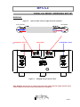
USERS GUIDE STEREO POWER AMPLIFIER DPA 6.4 DPA 6.4 INDEX UNPACKING page 2 GENERAL INFORMATION page 3 SWITCHES AND INDICATORS page 5 CABLES AND CONNECTIONS page 6 PARALLEL MONO / BRIDGING SET-UP page 8 TROUBLESHOOTING page 10 TECHNICAL SPECIFICATIONS page 11 WARRANTY page 12 PAGE 1 DPA 6.4 UNPACKING Please read the User Guide carefully before attempting to use this apparatus. The Users Guide comprises general and specific information on adaptations/adjustments to give you the best possible performance of the apparatus. Please store the packing materials for later use. When the apparatus is unpacked, please check that it has not been exposed to any damage and that the package contains the following items: 1 pc. Dynamic Precision DPA 6.4 2 pcs. mains fuses T5A. IEC127 1 pc. users guide for DPA 6.4 Note: Please report immediately any damages, defects or shortcomings to your dealer. PAGE 2 DPA 6.4 GENERAL INFORMATION We congratulate you on your choice of a Dynamic Precision DPA 6.4. The technical performance of this product is based on the company’s unique electronics circuit design to achieve the best possible musical reproduction. This apparatus is electronically balanced and DC-coupled to optimise pulse response and low noise. All Dynamic Precision products are wide bandwidth products (see page 10), so please observe the following: 1. The internal power supply (ies) of power amplifiers or any other high power equipment normally generate noise which «leaks» to the mains. This noise may be picked-up and amplified in preamplifiers, CD players, etc. Therefore, it is advised to use Dynamic Precision mains filters 1 for all products interconnected by signal cables. If high power HF-transmitters are located in the area, please use ferrite2 cores on all signal cables, and place these as close to the signal input terminals as possible. Ferrite should be used on the mains cords also,, and placed as close to the chassis as possible. Ferrite must never be installed on loudspeaker cables. 2. To have a separate 16-Amperé line to the stereo equipment is an obvious advantage, preferably with a separate ground wire. The reason for this is to avoid noise from domestic appliances. 3. Only shielded signal cables shall be used. Please keep the loudspeaker cables separated from the signal- and mains cables. The signal cables for the left (L) and right (R) channels shall be adjacent to each other, and preferably twisted and separated from mains cords. 1. If using an ungrounded mains line please check the polarity on the mains plug to reduce common mode noise3. Turning on all apparatuses without connecting the signal cables. When this is done, measure the AC-voltage4 (please use a digital AC voltmeter) by holding one of the measuring sticks in your hand and place the other one on the amplifier chassis. Turn the mains plug to the position giving the lowest AC-voltage reading. Now, measure the voltage between the power amplifier and the other apparatuses, and turn the other apparatuses mains plug to the position giving the lowest AC-voltage reading. If you do not have an AC-voltmeter at your disposal, you can listen to the system to find the correct polarity of the mains plug. Always begin with the power amplifier and observe the treble for softness, sound and acoustical quality. 4. The power amplifier shall always be the device which is connected closest to the circuit breakers. Please place the power amplifier on a non-magnetic, preferably an electrical non-conductive material (wood or plastic), to avoid magnetic coupling to other components in the HI-FI system. However, steel racks are not recommended. It may be an advantage to install a mechanical insulation (shock absorbent wallboard or similar) between the amplifier and the base although the circuit boards are rubber insulated within the chassis. This amplifier has a passive cooling system, requiring at least 15 cm of unused space on top of it. 1 The mains filter attenuates high frequency noise from 50 kHz - 50 MHz. Ferrite is a magnetic material which attenuates high frequency noise from 0,5 MHz - 1 GHz. 3 Unequal capacitive coupling between the mains phases with reference to the chassis causes common mode noise. 4 AC = Alternating Current. 2 PAGE 3 DPA 6.4 CAUTION: READ THIS BEFORE OPERATING Dynamic Precision DPA 6.4. 1. Do not open the amplifier's cabinet as this might result in damage to the set, or electrical shock. 2. To prevent lightning damage, pull out the power cord during an electrical storm. 3. When removing the power plug from the wall outlet, always pull directly on the plug, never pull the cord itself. 4. Do not use force when operating the switches. 5. When moving the unit, be sure to first pull out the power plug and remove cords connected to other equipment. 6. Do not attempt to clean the unit with chemical solvent as this might damage the finish. Use a clean dry cloth. 7. Be sure to read the «Troubleshooting» section for advice on common operating errors before concluding that your unit is faulty. 8. Keep this manual in a safe place for future reference. PAGE 4 DPA 6.4 SWITCHES AND INDICATORS Figure 1. DPA 6.4 front panel SWITCHES Power supply OFF/ON switch. INDICATORS SIGNAL: Indicates an input signal of at least 5 mV. CLIP: Indicates ≥ 1% harmonic distortion on the output signal. POWER: Indicates that the amplifier is turned on. STANDBY: Illuminates for a while when the power is turned on, and during the following situations: 1. 2. 3. Temperatures higher than 110 °C measured on the cooling bracket. DC-voltage on either input or output terminals. High frequency signals on either input or output terminals. Note: High frequency signals is here defined as frequencies higher than 200kHz. When «STANDBY» is lit, the input signal is muted, and in turn, the amplifier’s power supply will be shut down, and simultaneously the loudspeaker outputs will be short-circuited. The «STANDBY» LED will start to flicker to indicate periodic muting of the input signal due to a high degree of signal clipping in the range of 15-20 kHz. PAGE 5 DPA 6.4 CABLES AND CONNECTIONS Figure 2. DPA 6.4 back panel. CONNECTIONS Note: All cables to be connected prior to turning the power on. The preamplifier, crossover network or any other equipment shall be turned on prior to the power amplifier. SIGNAL INPUT AND OUTPUT TERMINALS: This power amplifier is equipped with electronically balanced inputs using XLR-terminals (female). Pin allocation is as follows: • • • Pin 1 = GND/shield Pin 2 = signal (+) in phase Pin 3 = signal (-) anti-phase DPA 6.4 also has a set of (L and R channels) XLR-terminals (male) in parallel with the input terminals. These terminals shall be used when paralleling L and R channels or paralleling several DPA 6.4s. A specially prepared cable shall be used when paralleling or bridging DPA 6.4s, see pages 7 and 8. LOUDSPEAKER TERMINALS: The amplifier is equipped with 4 sets of binding post (screw fastening terminals). FUSES: A defective fuse shall only be replaced by an equivalent fuse. Using a fuse with an incorrect value can cause serious damage to the amplifier which is not covered by the warranty, and could start a fire. PAGE 6 DPA 6.4 CABLES AND CONNECTIONS AUDIO CABLES Balanced cables The audio inputs are equipped with XLR-terminals (male and female). Balanced signal sources shall always be connected using balanced cables as shown in Figure 3. The benefit of a totally balanced system is that any noise superimposed on the signal paths will be cancelled on the input. On the other hand, when using an unbalanced system there is no control of the noise in the system. This may cause a high level of out-band, high frequency signals to be applied on the input terminals. Such high-frequency signals could cause the amplifier to be loaded by high output currents that may increase the inter-modulation and result in an audible reduction of the overall sound quality. Unbalanced cables The DPA 6.4 is equipped with balanced inputs, but can be used with both balanced and unbalanced control amplifiers. When connecting unbalanced signal sources to the DPA 6.4, a «special cable» consisting of two inner-conductors and a shield shall be used. All conductors shall be terminated in both ends as shown in Figure 4. Authorised dealers of Dynamic Precision’s products can help and advice you how to choose the proper cables to be used. XLR-Female XLR-Male 1 1 3 3 2 2 Figure 3: Balanced to balanced XLR-cable. RCA-Male XLR-Male 1 3 2 Figure 4: Unbalanced to balanced cable PAGE 7 DPA 6.4 PARALLEL MONO / BRIDGING SET-UP BRIDGING: Figure 5 Special cable used to bridge the power amplifier. XLR-Female XLR-Male 1 1 2 2 3 3 Loudspeaker, plus (+) (-) Input signal Figure 6 Loudspeaker, minus Bridging using a special cable. Note: Bridging will result in an output power four times higher than the single channel stereo output. Please consult the technical specifications on page 10. PAGE 8 DPA 6.4 PARALLEL MONO / BRIDGING SET-UP PARALLEL MONO SET-UP: Figure 8 XLR-cable for parallel mono connection of the power amplifier. XLR- Female XLR-Male 1 1 2 2 3 3 Loudspeaker Bass section Input signal Figure 7 Loudspeaker Treble section Parallel mono connection using an XLR-cable. The loudspeakers must be equipped with separate connectors for the bass and treble sections. Remember to remove the strap between the bass and treble sections on the loudspeakers. This method is normally called BI-AMPING. Main advantages are the use of shorter loudspeaker cables and a separation of the bass and treble currents in the power amplifier. PAGE 9 DPA 6.4 TROUBLESHOOTING SYMPTOM Apparatus is put in STANDBY. POSSIBLE CAUSE 1: High frequency noise POSSIBLE SOLUTION 1: Insert a mains filter between the power amplifier and the main outlet. 2: Problem with the signal cable. 2: Check for proper grounding/shield of the cables, or replace the cables. 3: DC on the inputs. 3: Check if DC is present on the signal source output. 4: Overheating. 4a: Check if the loudspeaker cables are partially shortcircuited, or replace the cables. 5: Strong signal clipping. 4b: Ensure that the amplifier has at least 15 cm of free space on top. 5: Input level is too high. Humming sound heard from the loudspeakers. Degraded/defective shield on the Check or replace the cables. signal cables. No sound, but the indicators are lit. Fuses (T5A) may be defective. Replace the fuses and check the apparatus for proper operation. Check if the loudspeaker cables are wired correctly and/or if a shorteningcircuit has occurred. PAGE 10 DPA 6.4 TECHNICAL SPECIFICATIONS DPA 6.4 OUTPUT POWER, RMS, 20Hz-20kHz, @ 1% THD (clipping level) : 8Ω 4Ω 2Ω 8Ω Maximum output current: More than 60A per channel (120A peak) DISTORTION, THD @ 400W 20Hz-20kHz in a 4 Ω load: Less than 0.002% DISTORTION, THD @ 35V RMS, 1 kHz: Less than 0.0002% IM DISTORTION, CCIR 13 kHz and 14 kHz, 8 Ω load: Less than 0.0003% (typical 0.0002%) FREQUENCY RESPONSE: DC - 800kHz -3dB DC - 150kHz -0dB SLEW RATE: Greater than 250V/us DAMPING FACTOR: 1000 @ DC - 20kHz/8Ω SIGNAL/NOISE RATIO, Ref. 250W/8Ω load: 10Hz-80 kHz 22Hz-22kHz 10Hz-CCIR-QPK IEC-A weighted INPUT IMPEDANCE: 100 kΩ (100pF in parallel) GAIN: 31,7dB (38,4X) SENSITIVITY: 1,04 V RMS for 200W/8Ω CHANNEL SEPARATION: More than 120dB@ DC -100kHz COMMON MODE REJECTION RATIO: Better than 100dB@ DC -100kHz DIMENSION (W x H x D in mm) 455 x 210 x 360 WEIGHT (kg) 29 THD: RMS: load, 250W per channel load, 500W per channel load, 800W per channel load, 800W bridged mono 109dB 119dB 109dB 120dB Total harmonic distortion. The Root Mean Square of a voltage. Dynamic Precision reserves the rights to change or alter the specifications and/or the technical solutions without prior notice. PAGE 11 DPA 6.4 WARRANTY DURING THE WARRANTY PERIOD The warranty and purchasers/vendors contractual obligations are in accordance with the Sale of Goods Act. All warranties shall be void if any carelessness, misuse and/or unacceptable handling of the apparatus or any other conditions, which may be ascribed to the negligence of the purchaser of this product. If a claim is raised concerning the operation of this product, please return it to the authorised dealer accompanied by a copy of the original purchase receipt and a brief description of the fault symptoms. The purchaser is requested to leave their telephone number and/or address in the event the manufacturer needs further information to resolve the problem to the purchaser’s satisfaction. Manufacturer Dynamic Precision AS Industriveien 3 N-2020 SKEDSMOKORSET NORWAY Telephone: +47 63878199 Facsimile: +47 63878198 E-mail: [email protected] Web site: http://www.dynamicprecision.no/ Dynamic Precision is the registered trademark of Dynamic Precision. PAGE 12