1
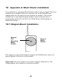
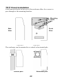
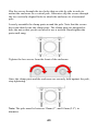
User Guide Mesh Router Mesh Router User’s Guide © Copyright 2012 Honeywell Analytics. 2 Mesh Router User’s Guide Contents 1 Warnings .................................................................................. 5 1.1 Operation Area and Conditions ................................. 7 1.1.1 Hazardous Areas classified by Zones ................. 7 1.1.2 Hazardous Areas classified by Divisions ............ 7 1.2 Instruction For Safe Use ............................................ 7 1.3 Use In Hazardous Areas............................................. 7 2 Standard Kit ............................................................................. 8 3 General Information ................................................................. 8 4 Physical Description .............................................................. 10 4.1 LCD Display (Monitoring) ...................................... 11 5 Specifications ......................................................................... 12 6 Operation................................................................................ 13 6.1 Turning The Mesh Router On .................................. 13 6.2 Turning The Mesh Router Off ................................. 15 6.3 Battery Charge Indicator .......................................... 15 7 Button Functions .................................................................... 16 7.1 Backlight .................................................................. 16 8 Deploying Mesh Routers ....................................................... 17 8.1 With FMC 2000 Controller...................................... 17 8.2 With Portable Monitors............................................ 18 9 Programming The Mesh Router............................................. 19 9.1.1 LCD Contrast .................................................... 21 9.1.2 Serial Number ................................................... 22 9.1.3 Firmware Version ............................................. 22 9.1.4 Factory Reset .................................................... 23 9.1.5 Edit Password.................................................... 24 9.1.6 Exit .................................................................... 25 9.2 Wireless.................................................................... 25 9.2.1 Ping Net ............................................................ 26 9.2.2 PAN ID Setup ................................................... 27 9.2.3 Join Net ............................................................. 28 9.2.4 Channel Setup ................................................... 29 9.2.5 Exit .................................................................... 31 10 “Panic” Function ............................................................. 32 10.1 Enabling/Disabling The “Panic Button” Function ... 32 3 Mesh Router User’s Guide 10.2 11 12 13 14 15 Using The “Panic” Function .................................... 34 10.2.1 Trigger All Relays...................................... 34 10.2.2 Trigger A Selected Relay ........................... 34 10.2.3 Clear Relays ............................................... 35 Internal Battery Replacement ......................................... 36 11.1 Proper Battery Disposal ........................................... 37 Troubleshooting .............................................................. 38 Mesh Router Alarm Signal Summary ............................. 40 Appendix A: Mesh Router Installation ........................... 41 14.1 Magnet-Mount Installation ...................................... 41 14.2 Fixed Installation ..................................................... 42 14.3 Magnetic Mount Alternative Installation ................. 45 Appendix B: Mesh Router External Battery Replacement .................................................................... 46 15.1 External Battery Usage ............................................ 46 15.2 External Battery Replacement Process .................... 49 4 Mesh Router User’s Guide 1 WARNINGS Read Before Operating This manual must be carefully read by all individuals who have or will have the responsibility of using, maintaining, or servicing this product. The product will perform as designed only if it is used, maintained, and serviced in accordance with the manufacturer’s instructions. Warning: Use only the Lithium battery or external rechargeable battery provided by Honeywell Analytics. This instrument has not been tested in an explosive gas/air atmosphere having an oxygen concentration greater than 21%. Substitution of components may impair suitability for intrinsic safety. Replace batteries only in non-hazardous locations. STATIC HAZARD: Clean only with a damp cloth. For safety reasons this equipment must be operated and serviced by qualified personnel only. Read and understand instruction manual completely before operating or servicing. Any rapid up-scale reading followed by a declining or erratic reading may indicate a gas concentration beyond upper scale limit, which may be hazardous. 5 Mesh Router User’s Guide Marking The Mesh Router is certified according to the IECEx scheme, ATEX and CSA for US and Canada as protected by intrinsic safety. The product is marked with the following information: RAE SYSTEMS 3775 N. 1st. St., San Jose CA 95134, USA FMC-400 Serial No/barcode: XXX-XXXX-000 IECEx TSA 10.0016X Ex ia IIC T4 Ex ia I 0575 IM1/II 1G Class I, Gr. A,B,C,D Ex ia IIC T4 T4 Ex ia I DNV 10 ATEX 83388X Intrinsically Safe -40º C ≤ Tamb ≤ 50º C Warnings: • Use only internal battery provided by Honeywell Analytics. If you need support with the p/n, please contact Honeywell Analytics Representative. Do not replace internal battery in hazardous locations. • Ui: 3.6V; Ci: 78µF; Li/Ri: 3.5µH/ohm • Understand User’s Manual before operating or servicing. • Substitution of components may impair intrinsic safety. • To prevent ignition of flammable or combustible atmospheres, disconnect power before servicing. Applied Standards IECEx IEC 600790:2004 IEC 6007911:2006 ATEX EN 60079-0:2006 North America CAN/CSA-C22.2 No. 0-M91 EN 6007911:2007 CAN/CSA-C22.2 No. 157-92 C22.2 No. 142-M1987 UL 913 UL916 6 Mesh Router User’s Guide 1.1 Operation Area and Conditions 1.1.1 Hazardous Areas classified by Zones Mesh Router is intended to be used in hazardous areas or mines susceptible to firedamp classified zone 0, zone 1 or zone 2, within the temperature range of -40º C to +50º C, where gases of explosion groups IIA, IIB or IIC and T4 may be present. 1.1.2 Hazardous Areas classified by Divisions Mesh Router is intended to be used in hazardous areas classified for Class I Div. 1 or 2, within the temperature range of -40º C to +50º C, where gases of explosion groups A, B, C or D and temperature class T4 may be present. 1.2 Instruction For Safe Use Strictly follow the instructions for safe use. Application of the Mesh Router requires full understanding and strict observation of the instructions. 1.3 Use In Hazardous Areas Equipment which is intended for use in explosive atmospheres and which has been assessed and certified according to international regulations may be used only under specified conditions. The components may not be modified in any way. The appropriate regulations for service and repair must be properly observed during such activities. 7 Mesh Router User’s Guide 2 Standard Kit Router with antenna Maintenance tool User’s Guide 3 General Information The Mesh Router is a dedicated router for relaying the wireless signals in a Mesh network and does not include a toxic gas sensor. The Mesh Router enables a flexible, robust wireless network that provides reliable, low-cost operation. It also works in a ProRAE Guardian network with a PC, and it supports point-to-point and point-to-multi-point networks. MeshGuard network with an FMC-2000 controller MeshGuard network with ProRAE Guardian running on a PC controller Portable monitors in a network with an EchoView Host (Mesh Routers with 869MHz or 900MHz radios only; 2.4GHz is not supported in systems with portable monitors) 8 2.1 Mesh Router User’s Guide Key Features Up to 45 days continuous operation using external battery box IEEE 802.15.4 Mesh network functionality with 64-bit encryption Mesh network with auto network forming and configuration Operating distance: up to 300 m, line of sight Very low-cost installation − no hardwiring involved Large area coverage with multi-hop mesh network Field-replaceable battery Loud audio alarm, 90dB @ 30cm (12″) Easy-to-read continuous display of signal strength Bright red flashing alarm Highly resistant to RFI interference IP-65 rated for outdoor use in harsh environments 9 Mesh Router User’s Guide 4 Physical Description 1 6 2 5 3 4 1 2 3 4 5 6 LED alarm LCD (with backlighting) Buzzer alarm Battery cover (on bottom) Y/+, MODE, and N/- keys Antenna 10 Mesh Router User’s Guide 4.1 LCD Display (Monitoring) 1 1 2 3 4 5 6 2 4 3 5 Online/Offline status Pan ID Channel EUI (Extended Unique Identifier) Battery strength indicator (percentage) Signal strength indicator (percentage) When you press [MODE], Online/Offline status is replaced by signal strength: 6 11 Mesh Router User’s Guide 5 Specifications RF Certifications Display Audible alarm Visual alarm Calibration RF EM Immunity Operating Range Receiver Sensitivity User Interface Power Supply Max Current Consumption Operation Time Operating Temperature Humidity Dimensions Weight Package Mounting FCC Part15 R&TTE Directive 1995/5/EC Customized LCD (1 x 1.5″) with backlight 90dB @ 30cm 2 super-bright red LEDs None necessary IEEE 802.15.4/Zigbee with mesh stack No effect when exposed to 0.43mW/cm2 RF interference (5-watt transmitter at 12") Minimum of 300 meters, line of sight Minimum -95dBm Three keys (Y/+, MODE, N/-) D-size Lithium primary battery, +3.6V [email protected] during transmission <[email protected] during standby Internal Battery: >10 days External Battery: >45 days -40° to +50° C (-40° to 122° F) 0% to 95% relative humidity, non-condensing 26.5cm x 9.5cm x 5.5cm (10.5″ L x 3.7″ W x 2.1″ H) 0.6 kg (1.3 lbs) IP-65 Optional stainless-steel bracket mount or magnetic mount; wall mount for external battery FCC Part 15 Statement This device complies with Part 15 of the FCC rules. Operation is subject to the following two conditions: (1) This device may not cause harmful interference, and (2) this device must accept any interference received, including interference that may cause undesired operation. 12 Mesh Router User’s Guide 6 Operation The Mesh Router only operates in RTR mode. Therefore, when it is turned on, it is always operational. Whenever you start Mesh Router, it tries to rejoin the last network it was part of. Therefore, if the network is within range and if the channel and Pan ID have not changed, the Mesh Router should be able to rejoin the network without action on your part. Make sure the battery is installed before operating the Mesh Router. Refer to page 36 for information on battery installation and replacement. 6.1 Turning The Mesh Router On Hold down the [MODE] key and release it when the Mesh Router beeps. The display indicates that it is now on: The Mesh Router performs a self-test. The display briefly shows the firmware version: Next, it shows the firmware’s build date and time: 13 Mesh Router User’s Guide This is followed by the Modem Type: Then the Mesh Router initializes connection with the wireless network. When the network is found and communication is established, the main reading screen is shown. It includes the Pan ID, EUI (Extended Unique Identifier), channel number, and battery charge (percentage): If the Mesh Router is unable to find a radio network to connect with, it searches, but if it is unsuccessful, it displays this screen: If you see this screen, check the following: • • • • • Is the antenna is attached? Does the Pan ID match the network you want to join? Does the Channel match the channel on which the other instruments are operating? Are the other instruments turned on and within range? Did you change the Pan ID or Channel? If so, restart the instrument. 14 Mesh Router User’s Guide 6.2 Turning The Mesh Router Off Hold down the [MODE] key through the “5…4…3… 2… 1… Power Off” sequence. When you see “Power off,” release the [MODE] key. The Mesh Router is off when the display is blank. 6.3 Battery Charge Indicator The Mesh Router’s internal battery is designed to provide power for up to 10 days. When the battery gets low, the Mesh Router beeps once per minute and the battery icon is empty. It is recommended that the battery be changed immediately, to minimize disruption. Battery power is indicated by “B:” followed by a number and a percent sign. For example, B: 100%. The battery should be replaced before it is completely discharged. See page 36 for the replacement procedure. When the battery is completely depleted, the LCD displays “Power off.” and the LED and buzzer alarm activate once per second. The Mesh Router shuts down after you press any key, or shuts down automatically if you do not press a key for 60 seconds. Note: An external power source, the RAE PowerPak, can be used as a substitute for the internal battery. See page 46 for installation details. 15 Mesh Router User’s Guide 7 Button Functions The three buttons provide fast access to functions in the Mesh Router. • • • Press [MODE] to view signal strength. Press [Y/+] to initialize connection with the network. Press [N/-] to ping the network. 7.1 Backlight Whenever you press the [Y/+], [MODE], or [N/-] key while viewing the data, the backlight turns on for two seconds and then shuts off. 16 Mesh Router User’s Guide 8 Deploying Mesh Routers Important! Before deploying a Mesh Router, it is important to have the Pan ID and Channel number on which the rest of the network is operating. Without these numbers programmed into your Router, you cannot make it communicate with the network. 8.1 With FMC 2000 Controller When deploying a MeshGuard network that utilizes Mesh Routers, follow this setup order: 1. Turn on the FMC2000 Controller. 2. Turn on a Mesh Router and use it to measure signal strength at each prospective detection location. Press [MODE] on the Mesh Router to see the signal strength: Signal strength a. If the signal strength reading on the Mesh Router is 30% or greater, then that indicates a MeshGuard or MeshGuard LEL will communicate reliably from this location with the FMC2000 controller. Locate and turn on a MeshGuard or MeshGuard LEL detector here. b. If readings are below 30%, relocate the Mesh Router until the reading is 30% or higher. If this new location is unacceptably far from the desired detection location, an additional Mesh Router or MeshGuard in RTR mode is needed to relay the signal from this new location. 17 Mesh Router User’s Guide 3. Follow this procedure until all MeshGuard or MeshGuard LEL detectors in the network are deployed. Check communication reliability for all detectors and routers at the FMC2000. 8.2 With Portable Monitors When deploying a wireless network that utilizes Mesh Routers, portable monitors (such as the ToxiRAE Pro, MultiRAE family, etc.), and an EchoView Host, check that all units on the network use the same PAN ID and Channel. Then follow this setup order: 1. 2. 3. 4. Turn on the Mesh Routers. Turn on the EchoView Host. Turn on the monitors. If any of the units do not automatically join the network, check their network settings and perform a Join Network. 18 Mesh Router User’s Guide 9 Programming The Mesh Router Programming Mode is accessed by first providing the correct password. Press and hold [MODE] and [N/-] until you see this screen: Input the 4-digit password: • Increase the number from 0 through 9 by pressing [Y/+]. • Decrease the number from 9 through 0 by pressing [N/-]. • Step from digit to digit using [MODE]. Once all the four digits have been entered, press [MODE] again to see the following screen appear. Press [Y/+] to enter the password. If you make a mistake, you can cycle through the digits by pressing [MODE] and then using [Y/+] and [N/-] to change the number in each position. Note: The default password is 0000. If your password is incorrect, you see this screen: After a few seconds, the Mesh Router exits to its main screen. 19 Mesh Router User’s Guide When you have successfully entered Programming Mode, you see this screen: Note: If you do not make a selection in 60 seconds, the Mesh Router automatically exits to the main screen. Press [Y/+] or [N/-] to scroll to “Settings,” “Wireless,” or “Exit.” Then press [MODE] to select your choice. Settings provides information about your instrument. Some screens are readonly (you cannot edit them), but other screens allow you to change settings. Wireless consists of parameters you can set/change that affect wireless functionality, network configuration, etc. Settings include some read-only information (Serial Number and Firmware Version) and some settings that you can change. Press [Y/+] to scroll up or [N/-] to scroll down. Note: The next screen contains additional options: Note: The scrolling “wraps,” so once you reach the first or last item, it starts scrolling through the items again. 20 Mesh Router User’s Guide Six choices (including Exit) are available: • • • • • • LCD Contrast Serial Number (read-only) Firmware Version (read-only) Factory Reset Edit Password Exit To make a selection, scroll until the circle to the left of your choice is black, and then press [MODE]. Note: If you do not make a selection in 60 seconds, it automatically exits to the main screen. 9.1.1 LCD Contrast The display’s contrast is adjustable via this menu. To access it, press [MODE] when its name is highlighted (dark circle): The contrast value is shown in the display. Step through the digits from left to right by pressing [MODE]. Change a digit’s value by pressing [Y/+] to increase and [N/-] to decrease. After the third digit, you see a flashing “?” • Save your changes by pressing [Y/+]. • Exit without saving changes by pressing [N/-]. • Step back to the first digit by pressing [MODE]. 21 Mesh Router User’s Guide 9.1.2 Serial Number This shows the Serial Number of the Mesh Router. To view it, press [MODE] when “Serial Number” is highlighted (dark circle): The serial number is shown in the display: Press [MODE] to return to the Settings menu. If you do not make a selection in 60 seconds, the unit automatically exits to the menu. 9.1.3 Firmware Version This shows the firmware version incorporated in the instrument. It is read-only. You cannot make changes to the information. To view it, press [MODE] when its name is highlighted (dark circle): Press [MODE] to return to the Settings menu. If you do not make a selection in 60 seconds, it automatically exits to the menu. 22 Mesh Router User’s Guide 9.1.4 Factory Reset You can perform a factory reset to the instrument’s original settings. To access it, press [MODE] when its name is highlighted (dark circle): You are asked whether you want to perform the factory reset: To perform the reset, press [Y/+]. To exit without performing the reset, press [N/-]. While the Mesh Router is being reset to its original factory settings, the screen shows that the activity is taking place: When the reset is complete, this screen appears: Then the unit returns to the Settings menu. 23 Mesh Router User’s Guide Note: If you perform a factory reset, all of your settings are removed and cannot be retrieved. 9.1.5 Edit Password You can change the password by selecting “Edit Password.” At this screen, input your new password over the old one (or the default): • Increase the number from 0 through 9 by pressing [Y/+]. • Decrease the number from 9 through 0 by pressing [N/-]. • Step from digit to digit using [MODE]. Note: If you make a mistake, you can cycle through the digits by pressing [MODE] and then using [Y/+] and [N/-] to change the number in each position. Once all the four digits have been entered, press [MODE] again to see the following screen appear. • Save your changes by pressing [Y/+]. • Exit without saving changes by pressing [N/-]. • Step back to the first digit by pressing [MODE]. 24 Mesh Router User’s Guide Saving the password takes a moment, and a screen indicates that it has been successfully saved: 9.1.6 Exit Scroll until “Exit” is selected. Press [MODE] to return to the Programming Menu. Note: If you do not make a selection in 60 seconds, it automatically exits to the menu. 9.2 Wireless Wireless consists of editable parameters and actions to configure, form, and test a closed-loop wireless network. Under Programming Menu, select “Wireless.” Press [Y/+] to scroll up or [N/-] to scroll down through wireless submenus. Note: When you reach the last item and continue scrolling, a second screen appears: 25 Mesh Router User’s Guide The scrolling “wraps,” so once you reach the first or last item of either screen, it starts scrolling through the items in the other screen again. Five choices (including Exit) are available: • • • • • Ping Net PANID Setup Join Net Channel Setup Exit To make a selection, scroll until the circle to the left of your choice is black, and then press [MODE]. Note: If you do not make a selection in 60 seconds, it automatically exits to the main Programming Menu. 9.2.1 Ping Net Pinging tests the radio connection between the Mesh Router and other units on its network. (A “ping” is a short signal sent to the network to prompt a reply; it contains no other data.) Scroll until “Ping Net” is selected. Press [MODE] to ping the network. This message appears: Press [Y/+]. The Mesh Router broadcasts a ping signal to its network. All devices in the network that receive the ping signal respond with a beep if 26 Mesh Router User’s Guide they are within the range. You can also ping from an instrument in the network. If it is within range, the Mesh Router responds with a beep and an LED light flash. If a network ping is unsuccessful, check the following: • • • • Is the antenna attached? Does the PAN ID match the PAN ID of other instruments in the network? Does the Channel match the channel on which the other instruments are operating? Are the other instruments turned on and within range? 9.2.2 PAN ID Setup All units on a network must be programmed with the same PAN ID (Personal Network Identifier) to ensure communication compatibility. When you see this screen, press [MODE] to view the current PAN ID or to change it: Important! The allowed range for PAN ID numbers is 001 through 999. The screen shows the PAN ID, with the cursor blinking on the first digit. Step through the digits from left to right by pressing [MODE]. Change a digit’s value by pressing [Y/+] to increase and [N/-] to decrease. After the third digit, you see a flashing “?” 27 Mesh Router User’s Guide • • • Save your changes by pressing [Y/+]. Exit without saving changes by pressing [N/-]. Step back to the first digit by pressing [MODE]. Note: If you do not press a key within 60 seconds, the screen reverts to the programming Menu screen showing Settings, Modem, and Exit. 9.2.3 Join Net This screen is for joining an existing network. When you see this screen, press [MODE] to join a network. This function allows the radio to scan all available channels and choose the least-congested one: The screen now displays a message asking if you want to confirm your choice to join a network: • • Press [Y/+] to join a network and automatically find the best channel to operate on. Press [N/-] to exit without joining a network. While the instrument starts joining a network, this message appears: 28 Mesh Router User’s Guide Once the device has selected the least-congested channel and a network is joined, this message is displayed: 9.2.4 Channel Setup All units in a network must operate on a single channel. The available channels vary by the internal wireless modem’s frequency, and channel ranges are set by Honeywell Analytics to correspond with the wireless modem frequency. These are the modem frequencies and channel ranges: 869 MHz (for use with portable monitors and EchoView Host): Channel 0 (channel cannot be changed) 900 MHz (for use with portable monitors and EchoView Host): Channels 1 through 10 2.4GHz (for use with MeshGuard detectors): Channels 11 through 26 Note: You can use “Form Net” to automatically have the Mesh Router select the least-congested channel. Scroll until “Channel Setup” is selected. Press [MODE] to view or change the channel. The range of available channels is shown in parentheses. The screen also shows the channel number, with the cursor blinking on the first digit: 29 Mesh Router User’s Guide Step from digit to digit from left to right by pressing [MODE]. Change a digit’s value by pressing [Y/+] to increase and [N/-] to decrease. When you press [MODE] you see a flashing “?” after the second digit: • • • Save your changes by pressing [Y/+]. Exit without saving changes by pressing [N/-]. Step back to the first digit by pressing [MODE]. If you have saved the channel number successfully, you see this screen: Important! Remember that the range of allowed channels for instruments on a Mesh Router’s network depends on the wireless modem frequency. Therefore, you may not be able to change the channel to a number outside of its assigned set of numbers. If you select an incompatible channel number, you will see this screen, and then the Mesh Router returns to the Wireless menu. 30 Mesh Router User’s Guide 9.2.5 Exit To exit Wireless and return to the main Programming Menu, scroll until “Exit” is shown: With “Exit” selected, press [MODE]. The Mesh Router now returns to the Programming Menu screen. 31 Mesh Router User’s Guide 10 “Panic” Function The Mesh Router has a “Panic” function, where you can manually trigger the relays at the main FMC2000 controller in the network. This must be configured in the Mesh Router in advance. This function allows you to trigger any individual relay or all relays simultaneously. 10.1 Enabling/Disabling The “Panic Button” Function Note: By default the “Panic Button” function is disabled. 1. Start the Mesh Router in Diagnostic mode by pressing and holding the [Y/+] and [MODE] keys simultaneously. 2. Once startup is completed and the main screen is shown, enter Programming mode by pressing and holding [MODE] and [N/-] simultaneously. 3. Provide the 4-digit password and press [Y/+] to enter it. Note: The default password is “0000.” This screen appears: 4. Press [N/-] until “Operating Mode” is highlighted. 5. Press [MODE] to select “Operating Mode.” “Panic Enable” or Panic Disable is highlighted. or 32 Mesh Router User’s Guide 6. Press [MODE] to make your selection. You are asked to confirm your selection. or 7. Press [Y/+] to save it or [N/-] to cancel any change. The change is registered, and you see the “success” screen: or After a few seconds, it returns to the menu screen with “Operating Mode” selected. Press [N/-] to advance to the screen with “Exit” highlighted. 8. Press [MODE] to exit to the main operating screen. 33 Mesh Router User’s Guide 10.2 Using The “Panic” Function The “Panic” function is designed so that it is very difficult to invoke by accident. Start from the normal operating mode screen: 1. From the normal operating mode screen, press and hold all three buttons until you see this screen: 2. Now press “Trigger Relays.” This screen is now shown: 10.2.1 Trigger All Relays With “All Relays” highlighted, press [MODE] to trigger all relays simultaneously. 10.2.2 Trigger A Selected Relay Scroll down the list of relays (1 through 5) by pressing [N/-]. Once you have highlighted the individual relay you want to trigger, press [MODE]. This triggers only that one selected relay. 34 Mesh Router User’s Guide Note: The relay on the FMC2000 controller remains triggered until it is cleared, either at the FMC2000 or at the Mesh Router. Also, the word “ONLINE” on the Mesh Router flashes on and off until you clear the relays. 10.2.3 Clear Relays Clear relays clears all of the relays on the controller, even if only one relay was triggered. Select “Clear Relays” and then press [MODE] to clear the relays. After clearing the relays, you can exit by using [N/-] to scroll down to “Exit.” Then press [MODE]. The main screen is shown: When the relays are cleared, the word “ONLINE” no longer flashes on and off, and returns to its normal state. 35 Mesh Router User’s Guide 11 Internal Battery Replacement Battery compartment Maintenance tool 3-pin end Hexagonal end 1. Use the 3-pin end of the tool to unscrew and open the battery cover by turning it counterclockwise. 2. Remove the battery. 3. Insert the new battery with its positive (“+”) pole towards inside of the unit. 4. Replace the battery cover by turning it clockwise with the 3-pin end of the tool. 36 Mesh Router User’s Guide Note: Only Change battery in a safe location and use the battery by Honeywell Analytics provided. After changing the battery, wait at least 60 seconds before turning the Mesh Router on. Battery Battery cover Warning Only change internal battery in non-hazardous locations and use the battery provided by Honeywell Analytics. If you need support with p/n, please contact Honeywell Analytics Representative. Only remove the external battery adapter in non-hazardous locations. 11.1 Proper Battery Disposal The Waste Electrical and Electronic Equipment (WEEE) directive (2002/96/EC) is intended to promote recycling of electrical and electronic equipment and their components at end of life. This symbol (crossed-out wheeled bin) indicates separate collection of waste electrical and electronic equipment in the EU countries. This product may contain one or more Nickel-metal hydride (NiMH), Lithium-ion, or Alkaline batteries. Specific battery information is given in this user guide. Batteries must be recycled or disposed of properly. At the end of its life, this product must undergo separate collection and recycling from general or household waste. Please use the return and collection system available in your country for the disposal of this product. 37 Mesh Router User’s Guide 12 Troubleshooting Failure Symptom Cannot turn on Controller cannot receive the Mesh Router’s signal Cause Solution Battery charge too low Replace battery Battery has been changed Wait at least 60 seconds to turn on Mesh Router New battery needs to be discharged before use Contact your Honeywell Analytics Representative Too much distance between the Mesh Router and the controller The distance should be 300 m, line of sight. Relocate Mesh Router(s) There is an obstruction between the Mesh Router and the controller. Controller does not receive completed data packet Relocate the Mesh Router or deploy more Mesh Routers Press [Y/+] on the detector to force it to send data packets Replace battery Battery is low Mesh Router and controller have different Pan ID numbers No Antenna Icon There is no reader or controller nearby. Set all units to the same Pan ID number Move the Mesh Router closer to a working controller or reader. Make sure the selected The controller or networks match. reader’s network has changed. Move the Mesh Router The Mesh Router is out close to a working 38 Mesh Router User’s Guide of its RF range. controller or reader and Press [Y/+] Replace battery Battery is low Others Turn Mesh Router off and on again. Consult Honeywell Analytics Technical Service Ordering Replacement Parts: If you need replacement parts please contact Honeywell Analytic Representative. 39 Mesh Router User’s Guide 13 Mesh Router Alarm Signal Summary Alarm Mode When LCD Battery Low < 3.2V (“empty” battery icon) Battery Exhausted < 3.1V 40 Buzzer & LED 1 beep per minute 1 beep per second Mesh Router User’s Guide 14 Appendix A: Mesh Router Installation Two methods for mounting Mesh Router make it easy to install. The first method uses a magnet that screw onto the rear of the Mesh Router, making ideal for moving from one location to another. The second method uses a specially designed stainless-steel enclosure that is permanently mounted. It protects the Mesh Router from damage in industrial settings. 14.1 Magnet-Mount Installation Magnet For Mounting Mesh Router Rear of Mesh Router This magnet is powerful enough to support the Mesh Router when it is placed against a flat steel or iron surface. Important! Keep the magnet away from computer hard drives. The strong magnet can corrupt or erase data on these. 41 Mesh Router User’s Guide 14.2 Fixed Installation Four reinforced holes in the rear of the enclosure allow for a screw to pass through to the mounting brackets. Mounting Holes Side View Front View The enclosure can be mounted to a vertical or horizontal pole. Vertical pole Horizontal pole 42 Mesh Router User’s Guide Slip the screws through the two holes that are side by side in order to mount the enclosure to a vertical pole. Otherwise slip the screws through the two vertically aligned holes to attach the enclosure to a horizontal pole. Loosely assemble the clamp parts around the pole. Note that the screws have nuts that fit into the clamp parts. The clamp parts are designed to hole the nut so that you do not need to use a wrench. Hand-tighten the parts until snug. Tighten the hex screws from the front of the enclosure: Once the clamp parts and the enclosure are securely held against the pole, stop tightening. Note: The pole must be between 25mm (1″) and 63mm (2.5″) in diameter. 43 Mesh Router User’s Guide Next, place the Mesh Router into the enclosure: 1. 2. 3. 4. Lift up the hinged cover of the enclosure. Slide the Mesh Router into the enclosure from the top. Close the cover of the enclosure. Insert the hex screw into the cover’s locking portion, and tighten it. 5. The Mesh Router is now ready to use. 1 2 3 44 4 5 Mesh Router User’s Guide 14.3 Magnetic Mount Alternative Installation The magnet-mount disc can be attached to the steel enclosure instead of the clamps. This approach provides the protection of the enclosure with the ease of installation afforded by the magnetic mounting. 1. Insert screw through magnetic disc. 2. Place the magnetic disc over the bottom hole on the rear of the enclosure. 3. Tighten the screw until the disc is snug. Side View Rear View 45 15 Appendix B: Mesh Router External Battery Replacement Warning: Only remove the external battery adapter in nonhazardous locations. Note: For clarity, Mesh Router’s optional stainless-steel enclosure is not shown. Adapter 3-pin end Maintenance tool Hexagonal end 15.1 External Battery Usage An external battery unit, the provided by RAE PowerPak, is used to power a Mesh Router in fixed installations or in situations where extended battery life is necessary. The connector from the external battery screws into the Mesh Router’s battery compartment. Bottom views of the Mesh Router in its steel enclosure are shown in the procedure below. Mesh Router User’s Guide 1. Remove battery cover with the 3-pin end of the sensor and battery removal tool by turning counterclockwise. Power end of cable 2. Lift off the cover. 3. Insert the power end of the cable connected to the Power Pak. Cord to RAE PowerPak 4. Use the open hex end of the wrench, and with both pins mated with the two holes on the power end, tighten by turning clockwise until it is snug. Do not overtighten. Consult the RAE PowerPak User’s Guide for further connection and charging information. The Mesh Router is permanently mounted to a solid surface by first securing it in its steel enclosure (a screw through the back mates with the Mesh Router) and then securing the enclosure to a solid surface such as a wall or the metal mounting plate that holds both the Mesh Router and the RAE PowerPak. 47 Mesh Router User’s Guide Screw in rear of enclosure mates to rear of Mesh Router Front, side, and rear views of the steel enclosure show how the Mesh Router is secured for mounting. With the Mesh Router securely in its housing, you can remove the cover over the battery compartment so that you can place the connector from the provided by RAE PowerPak into the Mesh Router. Use the maintenance tool as shown. Maintenance tool 48 Mesh Router User’s Guide 15.2 External Battery Replacement Process RAE PowerPak External battery replacement 1. 2. 3. 4. 5. 6. Unplug the battery connector. Loosen the safety screw holding the battery. Mount a new battery on the mounting bracket. Tighten the safety screw. Connect the Mesh Router to the battery. Switch on the Mesh Router. 49 Mesh Router User’s Guide Year Of Manufacture To identify the year of manufacture, refer to the serial number of the instrument. The letter in the serial number indicates the year of manufacture. For example, “M” indicates the manufacturing year is 2010. Letter J K M N P Q R S T U V W Year 2008 2009 2010 2011 2012 2013 2014 2015 2016 2017 2018 2019 50 Find out more www.honeywellanalytics.com Contact Honeywell Analytics: Europe, Middle East, Africa Life Safety Distribution AG Javastrasse 2 8604 Hegnau Switzerland Tel: +41 (0)44 943 4300 Fax: +41 (0)44 943 4398 [email protected] Customer Service: Tel: +800 333 222 44 (Freephone number) Tel: +41 44 943 4380 (Alternative number) Fax: +800 333 222 55 Middle East Tel: +971 4 450 5800 (Fixed Gas Detection) Middle East Tel: +971 4 450 5852 (Portable Gas Detection) India Tel: +91 124 4752700 Americas Honeywell Analytics Inc. 405 Barclay Blvd. Lincolnshire, IL 60069 USA Tel: +1 847 955 8200 Toll free: +1 800 538 0363 Fax: +1 847 955 8210 [email protected] Asia Pacific Honeywell Analytics Asia Pacific #701 Kolon Science Valley (1) 43 Digital-Ro 34-Gil, Guro-Gu Seoul 152-729 Korea Tel: +82 (0)2 6909 0300 Fax: +82 (0)2 2025 0328 India Tel: +91 124 4752700 [email protected] Technical Services EMEAI: [email protected] US: [email protected] AP: [email protected] www.honeywell.com Please Note: While every effort has been made to ensure accuracy in this publication, no responsibility can be accepted for errors or omissions. Data may change, as well as legislation and you are strongly advised to obtain copies of the most recently issued regulations, standards and guidelines. This publication is not intended to form the basis of a contract. 13427_REV C_12/2012 H_MAN0976_EMEAI P/N F04-4002-000 © 2014 Honeywell Analytics