1
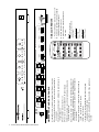
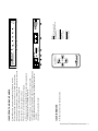
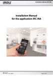
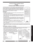
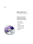
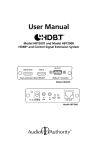
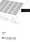
Installation and Operation
SELECT SOURCE
1
IR
Model HMX-244 4x4 Video/Audio Matrix
2
3
SELECT SOURCE
4
1
ZONE 1
2
3
SELECT SOURCE
4
1
ZONE 2
2
3
SELECT SOURCE
4
1
ZONE 3
2
3
4
POWER
ZONE 4
Model HMX-244
4-Source / 4-Zone HDMI Matrix Switching System
TMDS
POWER
5V DC
ZONE 4
OUTPUT
TMDS
A
ZONE 3
OUTPUT
TMDS
A
ZONE 2
OUTPUT
HDMI SOURCE INPUTS
TMDS
A
ZONE 1
OUTPUT
A
IR
B
HDMI
DDC
B
HDMI
DDC
B
HDMI
DDC
B
HDMI
DDC
SOURCE 4
INPUT
IR
SOURCE 3
INPUT
IR
SOURCE 2
INPUT
IR
SOURCE 1
INPUT
IR
RS-232
Audio Authority and the Double-A Symbol are registered trademarks
of Audio Authority Corp.
HDMI, the HDMI logo and High-Definition Multimedia Interface are
trademarks or registered trademarks of HDMI Licensing LLC.
Audio Authority® Corporation Lexington, Kentucky
www.audioauthority.com • 800-322-8346 • 859-233-4599
Warnings
To reduce the risk of fire or electric shock, do not expose this unit to rain or moisture.
!
•
•
•
•
•
•
•
2
The exclamation point symbol alerts users to important operating and
maintenance instructions in this booklet.
Read this manual before installing or using this product.
This product must be installed by qualified personnel.
Do not open the cover—there are no user-serviceable parts inside.
Do not expose this unit to excessive heat.
Install only in dry, indoor locations.
Do not obstruct the ventilation slots.
Clean the unit only with a dry or slightly dampened soft cloth.
Audio Authority® Model HMX-244 User Manual
Model HMX-244
4-Source / 4-Zone HDMI Matrix Switching System
1.0 INTRODUCTION
2.0 CHECKING PACKAGE CONTENTS
Thank you for purchasing this Model HMX-244 HDMI
Matrix Router from Audio Authority. It is designed to route
digital audio and video signals from four different HDMI
sources to four HDMI displays without signal degradation
or loss of encryption. All displays have access to any of the
four sources connected to the HMX-244 at any time.
Before attempting to use this matrix router, please check
the packaging and make certain the following items are
contained in the shipping carton:
The HMX-244 also features a longer distance, alternative
Cat 5 output for each zone, terminated by a Cat 5 zone
receiver (Model 1380R, sold separately).
• HDMI matrix router
The HMX-244 is HDCP v1.1 compliant, and HDMI
compliant, supporting HDMI 1.3 features including deep
color video, Dolby TrueHD, and DTS-HD Master Audio.
Audio Authority offers an extensive line of audio and video
switchers, converters, extenders and distribution amps
available for purchase online at www.audioauthority.com.
1.1 FEATURES
• Delivers four HDMI source signals to any or all of four
compatible video displays
• Optional Cat 5 zone receiver (Model 1380R) terminates
dual Cat 5e/6 cables for runs over 50 ft. (15m) up to a
maximum distance of 130 ft. (40m)
• 1380R provides a built-in IR receiver that transmits IR
commands from the zone to the HMX-244 to switch
inputs and to pass IR commands to the sources
HMX-244 Matrix Unit
Each HMX-244 includes the following:
• IR remote control
• 5.5V (4A) DC power adapter
• Rack mount hardware
• User manual
1380R zone receiver (Optional)
Each 1380R includes the following:
• 1380R Cat 5 zone receiver
• IR remote control
• 5V (2A) power adapter
Note: Please retain the original packing material and
invoice in case you need to return the equipment. If
you find any items are missing, contact Audio Authority
immediately. Have the model number and invoice available
for reference when you call.
• Input switching can be performed through RS-232 or IR
• HDMI and HDCP compliant
• Supports deep color: 12 bits per TMDS channel (36 bit,
sum of all channels)
• Supports 480i/p, 576i/p, 720p, 1080i/p and multiple PC
resolutions
• Supports Dolby Digital Plus, Dolby® Digital TrueHD,
DTS-HD: Master Audio, and LPCM
• IR remote control, RS-232 control, or front panel control
Audio Authority® Model HMX-244 User Manual
3
4
Audio Authority® Model HMX-244 User Manual
POWER
5V DC
ZONE 4
OUTPUT
HDMI
F
ZONE 4
OUTPUT
DDC
G
TMDS
TMDS
B
A
B
A
HDMI
ZONE 3
OUTPUT
HDMI
ZONE 3
OUTPUT
A
DDC
DDC
TMDS
TMDS
IR
IR
DDC
B
A
B
A
HDMI
ZONE 2
OUTPUT
HDMI
ZONE 2
OUTPUT
ZONE 1
K Serial Port - accepts RS232 commands from home automation
devices
J IR Input Jack - connect Model 804-052 IR receiver (sold
separately) for remote IR input
I HDMI input for source
H Source IR Output Jack - repeats IR commands received by
1380R - connect IR emitter to source
G Cat 5 Zone Output - connect to Model 1380R zone receiver for
long cable runs to more distant zone. Either TIA/EIA 568A or
568B standards may be used provided it is straight through and
not crossover.
F HDMI Zone Output - connect directly to display and/or audio
system in nearby zone
E Power Jack - connect included 5.5V, 4A power supply
D Power Switch - turns matrix off or on
C Selected Source Indicator Light - indicates the selected source in
the specified zone
B Source Selection Button - push button cycles through available
source inputs
DDC
DDC
TMDS
TMDS
2
1
3
3
4
A
1
4
B
A
B
HDMI
ZONE 1
OUTPUT
HDMI
ZONE 1
OUTPUT
1
3
3
DDC
DDC
TMDS
TMDS
ZONE 2
2
ZONE 2
2
SELECT SOURCE
2
BZONE 1
SELECT SOURCE
C
1
A Infrared Receiver - accepts commands from IR remote controls
HDMI
HMX-244 Front and Back Panels
E
POWER
5V DC
Model HMX-244 4x4 Video/Audio Matrix
Model HMX-244 4x4 Video/Audio Matrix
SELECT SOURCE
SELECT SOURCE
4
4
B
A
B
A
H
IR
IR
1
1
1
ZONE 4
1
ZONE 3
1
ZONE 2
1
ZONE 1
POWER
I
SOURCE 4
INPUT
N
3
ZONE 3
2
SOURCE 4
INPUT
L
3
ZONE 3
2
SELECT SOURCE
SELECT SOURCE
2
2
2
2
3
3
ZONE 4
2
ZONE 4
2
SELECT SOURCE
4
4
3
3
3
3
4
OFF
4
OFF
4
OFF
4
OFF
AUTO
SOURCE 3
INPUT
O
M
IR
IR
IR
IR
SOURCE 1
INPUT
SOURCE 1
INPUT
J
IR
IR
K
RS-232
RS-232
POWER
POWER
D
2
SOURCE
3
IR Emitter pinout
Tip = Signal
Sleeve = Ground
HMX-244 VIDEO MATRIX
IR Receiver pinout
Tip = +5 Volts
Ring = Data
Sleeve = Ground
Use only 5V demodulated4IR
receivers such as Model 804-052
(sold separately)
Note:
1
O Zone off button- deselects
all sources
from zone
SELECT
N Source buttons for zone 1
MAuto mode - switches to lowest numbered
output with REMOTE
videoZONE
signal
present
CONTROL
L Power on/off button - turns matrix on or off
HMX-244 ir remote
SOURCE 2
INPUT
SOURCE 2
INPUT
HDMI SOURCE INPUTS
SOURCE 3
INPUT
HDMI SOURCE INPUTS
1
1
HMX-244
VIDEO MATRIX
IR
IR
4
4
SELECT SOURCE
Audio Authority® Model HMX-244 User Manual
5
K IR remote control source selection buttons
1380R IR remote
J Serial port connection *Not Used*
1
ZONE 4
1
ZONE 3
1
ZONE 2
1
ZONE 1
POWER
2
2
2
2
3
3
3
3
HMX-244
VIDEO MATRIX
4
OFF
4
OFF
4
OFF
4
OFF
AUTO
I Cat 5e/6 cables connected to HMX-244 zone output. Either TIA/EIA 568A
or 568B standards may be used provided it is straight through and not
crossover.
H HDMI Zone Output - connect directly to display or audio system
G IR Input Jack - connect Model 804-052 IR receiver (sold separately) to
send IR signals over Cat 5 to HMX‑244 matrix
F Power Jack - connect included 5V, 2A power supply
E Power Switch - turns zone receiver off or on
D Source button - push to select source in this zone
C Selected Source Indicator Light - indicates the selected source in the zone
B Power indicator light - shows power on or off status for zone receiver
A Infrared Receiver - accepts commands from IR remote controls
1380R Front and Back Panels
5V DC
IR IN
F
5V DC
HDMI OUTPUT
H
G
4
SELECT
SOURCE
1
3
HMX-244 VIDEO MATRIX
2
K
IR
IR IN
ZONE
REMOTE CONTROL
E
POWER
B
POWER
POWER
IR
A
HDMI OUTPUT
Model 1380R HDMI UTP Receiver
POWER
Model 1380R HDMI UTP Receiver
1
A
B
DDC
2
3
3
4
4
RS-232
J
IR Emitter pinout
Tip = Signal
Sleeve = Ground
IR Receiver pinout
Tip = +5 Volts
Ring = Data
Sleeve = Ground
D
SOURCE
RS-232
Use only 5V demodulated IR
receivers such as Model 804-052
(sold separately)
I
B
DDC
2
Note:
TMDS
1
A
TMDS
C
SOURCE
3.0 PLANNING A MATRIX SYSTEM
• Before installation, test the equipment for compatibility.
Temporarily connect all of the sources, audio receivers,
and displays to the matrix using short HDMI cables
to verify basic compatibility and function. If any
incompatibilities occur, connect the source and display
or audio receiver without the matrix in the signal path for
further HDMI troubleshooting.
• Since all of the displays connected to a particular source
will be receiving the same video signal resolution and
format (e.g. 1080p@60Hz) produced by the source,
make sure the source is set up to output the highest
resolution that all of the displays can accept. For
instance, if one display can accept a maximum input
resolution of 720p, all of the sources are limited to
720p output, and all displays will receive a maximum
resolution of 720p. This consideration is particularly
important if the TVs have a wide range of resolution
capabilities because the highest resolution sets may not
be allowed to perform to their best advantage.
• HDMI cable lengths should be kept as short as
possible. Use the Cat 5 output for cable runs over 50
feet. High resolution settings, refresh rate, and/or deep
color require increased bandwidth, and may effect the
maximum cable run length that can be achieved.
4.0 CONNECTING THE HARDWARE
• Turn off equipment that will be connected to the matrix.
Mount the matrix in an equipment rack if desired, using
the included rack ears. Otherwise, place the matrix on a
flat surface with adequate ventilation and access to the
front and rear panels.
• Connect a high quality HDMI cable from each HDMI
source to an input of the matrix. Cable lengths should be
kept as short as possible.
• Connect the outputs of the matrix to their destination
devices using HDMI cables OR dual Cat 5 cables at
each output – both types of output ports may not be
used at once. Use 1380R Cat 5 zone receivers where
cable lengths of 50 feet* or more are required. Either
TIA/EIA 568A or 568B standards may be used provided
it is straight through and not crossover. HDMI cables
perform differently depending on quality of cable and the
source equipment used.
• Connect the power adapter to an AC outlet and then to
the matrix.
• If you are using the RS-232 control function, connect a
standard serial cable from the controller to the HMX-244
RS-232 port.
• Turn on the HDMI sources and displays. Turn on the
matrix and after a pause for HDCP handshaking,
observe the source signals on the displays. The
HMX‑244 front panel LEDs light, indicating the active
sources in each zone.
* Proper function of HDMI matrix routers and distribution
systems depends on the use of high quality HDMI cables
with low loss, high bandwidth signal handling capabilities.
The distance specification cannot be guaranteed unless
cables used throughout the system meet these high
standards.
GETTING THE BEST RESULTS using hdmi
Many factors influence the performance of an HDMI switching system. Consider the following precautions to
ensure the best system performance.
• Resolution tracking. Refer to 3.0 “Planning a Matrix System” Set up the sources to output the best resolution
that all TVs can accept.
• Source resolution and video/sound quality. Sources, such as satellite receivers or cable boxes may output
at lower resolutions or deliver extremely compressed video material, yielding poor results. Consider the
sources when planning and troubleshooting your system.
• Output display devices. The quality of the output signal depends largely upon the type and quality of the
HDMI display devices used.
• Connection cables. HDMI cable design and quality are extremely important in long cable runs where
capacitance can severely degrade performance. Use premium cables; low quality cables are susceptible to
interference. Always use good strain relief methods to prevent cables from becoming loose over time.
• Distance between the sources and the displays. Using premium quality cables the sources may be located
up to 20m from the matrix, and the matrix may be up to 15m from each display device. Longer distances are
possible using advanced HDMI extenders with DDC correction.
• Interference. Nearby electrical devices can negatively affect signal quality. For example, older computer
monitors often emit strong electromagnetic fields that can interfere with the performance of adjacent video
equipment.
6
Audio Authority® Model HMX-244 User Manual
VIDEO CONNECTIONS
POWER
HDMI MATRIX
HMX-244
SOURCE 1
SOURCE 2
SOURCE 3
HDMI CABLE (UP TO 50 FT.)
ZONE 4
ZONE 3
HDTV
SOURCE 4
HDMI
HDTV
CAT 5E/6 CABLES
CAT 5E/6 CABLES (UP TO 130 FT.)
ZONE 2
1380R CAT 5
RECEIVER
ZONE 1
1380R CAT 5
RECEIVER
HDTV
HDTV
POWER
HDMI CABLE
POWER
AUDIO RECEIVER
HDMI CABLE
IR Connections
Use only 5V demodulated IR
receivers such as Model 804-052
(sold separately)
IR Receiver pinout
Tip = +5 Volts
Ring = Data
Sleeve = Ground
IR Emitter pinout
Tip = Signal
Sleeve = Ground
HDMI MATRIX
HMX-244
IR
CAT 5E/6 CABLES
IR
ZONE 2
1380R CAT 5
RECEIVER
SOURCE 1
SOURCE 2
SOURCE 3
SOURCE 4
ZONE 3
IR RECEIVER
IR EMITTERS TO
SOURCES
IR SIGNALS
Audio Authority® Model HMX-244 User Manual
7
6.0 OPERATING THE MATRIX switcher
6.3 RS-232 serial Control
The HMX-244 is a matrix switcher capable of routing
audio/video signals from any of four sources to any of four
displays. The matrix may be operated by the front panel
controls, an IR remote control, or by RS-232 through a
computer or other third party controller.
Connect a computer or other serial controller to the RS‑232
port on the rear panel using an RS-232 cable. The HMX244 serial commands are based on Windows™ OS super
terminal. Commands include on, off, and source selection
on any zone output.
The HMX-244 begins to operate as soon as power is
turned on, handshaking with sources and displays. Unused
ports do not operate
Chose the right COM when setting “super terminal” and
then set the parameters as follows:
6.1 Front Panel Controls
Repeatedly press the SOURCE button in the appropriate
zone until the desired source (1, 2, 3, or 4) is selected.
• Lights (1-4) indicate the source that is currently selected
to the zone output.
• If a source is not powered on, the HMX-244 skips to the
next available source.
• The Power light indicates that the unit is receiving
power.
6.2 IR Remote Controls
The HMX-244 includes a main remote control that can be
used at the head end matrix location. It controls sources for
all four zones. Each row of buttons represents a zone. To
disconnect all sources from a zone, press OFF.
Auto Mode may be used to avoid any TV showing a blank
screen. It automatically searches for a source input with
active video signal beginning with input 1. If no signal is
present, it searches input 2, 3, and 4. Override Auto Mode
in any zone by pressing one of the other source buttons.
Each 1380R Cat 5 zone receiver includes a zone IR
remote control. It controls only the zone output where the
1380R is located. The IR ports are only active when an
HDMI signal is present on both the source and respective
zone. If an external IR receiver is required, purchase a
5V demodulated IR receiver such as Model 804-052 from
Audio Authority.
Baud Rate: 4800 bps
Data bit: 8 Bits
Parity: None
Stop Bit: 1 bit
Data stream: None
• Each command should be two or three characters,
followed by a carriage return. After each command, the
HMX-244 responds with “successful operation”.
• The next command must be sent within three seconds or
the error message: ”Overtime instruction” appears.
• If an incorrect command is received, the error: “wrong
instruction” appears.
• If the input or output is not connected or not in powered
on, “ineffective instruction” appears.
Serial Commands
These commands are for the HMX-244 only. The serial
port on the Model 1380R receiver is not used.
The character for the zone output (A, B, C, or D) comes
first, then the number for the source input:
• zone 3 to source 2 = C3(carriage return)
• zone 1 to source 4 = A4(carriage return), etc.
To turn the HMX-244 on or off enter the following:
• ON(carriage return)
• OFF(carriage return)
To query the status of the HMX-244 enter the following:
• QS(carriage return)
Important: all serial commands must be terminated with a
carriage return and line feed.
Note:
Use only 5V demodulated IR
receivers such as Model 804-052
(sold separately)
IR Receiver pinout
Tip = +5 Volts
Ring = Data
Sleeve = Ground
IR Emitter pinout
Tip = Signal
Sleeve = Ground
POWER
HMX-244
VIDEO MATRIX
ZONE 1
1
OFF
2
3
ZONE 2
1
2
3
1
2
3
ZONE 4
1
4
OFF
Audio Authority® Model HMX-244 User Manual
4
OFF
2
3
ZONE
REMOTE CONTROL
1
4
OFF
ZONE 3
8
AUTO
4
2
SELECT
SOURCE
4
3
7.0 TROUBLESHOOTING
If the problem remains with one particular input, connect
that source to a different input using the same cable and
see if the problem moves to the new input. If it does, the
problem is with the source. Connect the source directly
to the lowest resolution display and adjust its output
settings and resolution until satisfactory function is
achieved.
• Make certain that the matrix is receiving power by
looking at the power LED. It should be illuminated and
not flickering. Intermittent operation generally means a
problem with the DC power adapter or low AC voltage.
Check the AC outlet for proper voltage, then consider
replacing the DC power adapter.
• If some lower resolution TVs do not display a picture,
make sure the source is producing a resolution that all
TVs can accept. Try 1080i, 720p and 480p. If possible,
manually set the sources to the desired resolution. In
some cases, hot-plugging a high resolution display may
actually reset the source to a resolution that cannot be
accepted by some other TVs.
• If displays seem to “lose signal” momentarily, it could be
normal HDMI switching behavior. All displays connected
to a source must handshake again when that source
is selected to a new display. This pause is normal and
required when switching HDCP encrypted signals.
• If some inputs function correctly and others do not,
interchange cables between sources and see if the
problem moves with the cables. If it moves, a bad cable
or cable connector is the probable reason for the trouble.
• If 1080p resolution, deep color, and/or lossless audio is
desired, very high bandwidth is required. HDMI cable
design and quality are extremely important in long
cable runs where capacitance can severely effect the
bandwidth available. If a zone is not receiving HDMI
signals, first make certain that the input cable is as short
as possible and none of the output cables are more than
15 meters long. Try reducing the resolution, color depth
and/or audio settings.
• Remember that HDMI devices communicate with
one another so the source device and all destination
devices must be fully HDMI compliant. In addition,
HDCP encryption requires processing dependent on the
equipment you have connected to both the source and
destination devices.
If a problem still persists after trying the above suggestions, contact the Audio Authority Technical Support department via
email: [email protected], or call 800‑322‑8346 or 859‑233‑4599.
8.0 Specifications
Signal Inputs/Output:
HDMI Connector
type A 19 pin female
Input DDC Signal
5 volts p-p (TTL)
Control Port
RS-232 female, mini-stereo
Operating Frequency:
Vertical Frequency Range
50/60Hz
Video Amplifier Bandwidth
2.25Gbps/225MHz
Resolutions:
Interlaced (50&60Hz)
480i,576i,1080i
Progressive (50&60Hz)
480p,576p,720p,1080p
Mechanical:
HMX-244 Cabinet Size (H-W-D)
1.75”x 17.2”x 6.9” (44x438x175mm)
Weight (HMX-244 Matrix)
4.9lb (2.2kg)
Warranty:
Limited Warranty
1 year parts and labor
Environmental:
Operating Temperature
0° to +70°C
Operating Humidity
10° to 85°C RH (no condensation)
Storage Temperature
-10° to +80°C
Storage Humidity
5% to 90% RH (no condensation)
Power Supply for HMX-244 Matrix
5.5V DC@4A; 20W
Power Requirement:
Regulatory Approvals:
Accessories Included:
Power Supply for 1380R Zone Receiver
5V DC@2A; 5W
HMX-244 Matrix and 1380R Receiver
FCC, CE, UL
Power Supply
FCC, CE, UL
AC Power Adapter
Input: AC 100-240V 50/60Hz, 1.5A
IR Extension Cable
3.5mm
Mounting Hardware
Rack ears for HMX-244
User Manual
12 pages, printed
Audio Authority® Model HMX-244 User Manual
9
9.0 LIMITED WARRANTY
If any consumer product from Audio Authority fails due to defects in materials or workmanship within one year from the
date of the original sale to the end-user, Audio Authority guarantees that we will replace the defective product at no cost.
Freight charges for the replacement unit will be paid by Audio Authority (ground service only). A copy of the invoice
showing the item number and date of purchase (proof-of-purchase) must be submitted with the defective unit to constitute
a valid in-warranty claim.
Units that fail after the warranty period has expired may be returned to the factory for repair at a nominal charge, if not
damaged beyond the point of repair. All freight charges for out-of-warranty returns for repair are the responsibility of the
customer. Units returned for repair must have a Return Authorization Number assigned by the factory.
This is a limited warranty and is not applicable for products which, in our opinion, have been damaged, altered, abused,
misused, or improperly installed. Audio Authority makes no other warranties either expressed or implied, including
limitation warranties as to merchantability or fitness for a particular purpose. Additionally, there are no allowances or
credits available for service work or installation performed in the field by the end user.
9.1 WARRANTY SERVICE PROCEDURES
If you suspect a product defect, contact Audio Authority’s Technical Service Department at 800-322-8346 or 859-233-4599
for assistance in verifying the problem. If a defect or potential defect is suspected, a replacement unit will be shipped
immediately on a defect-exchange basis and a Return Authorization Number will be issued for the return of the defective
product. Replacement units are sent out at the Manufacturer’s Suggested Retail Price which is debited to the Customer’s
Credit Card at the time of shipment. Once we receive the defective unit back at the factory, it will be evaluated under the
conditions of this warranty and if found to be in-warranty, a full credit will be issued to the Customer’s Credit Card. Return
freight charges for the defective unit are the customer’s responsibility. Please contact our Technical Support Department
for complete details concerning all in and out of warranty service matters.
We appreciate your confidence in our products and services and will always strive to meet or exceed your needs.
10.0 REGULATORY COMPLIANCE
The HMX-244 and 1380R have been tested for compliance with CE and FCC rules and regulations. Power supplies
included have been tested for compliance with UL, CUL, CE, PSE, and GS regulations and guidelines. This product and
its power supply are RoHS compliant.
11.0 CONTACT INFORMATION
If you have questions or require assistance with this product in areas not covered by this manual, please contact
Audio Authority using the information below.
Audio Authority Technical Support
800-322-8346 M-F 8:30 AM to 5:00 PM, EST
International: 859-233-4599 Fax: 859-233-4510
Send email to: [email protected]
Audio Authority Corporation
2048 Mercer Road
Lexington, Kentucky 40511-1071
USA
10
Audio Authority® Model HMX-244 User Manual
Audio Authority® Model HMX-244 User Manual
11
2048 Mercer Road, Lexington, Kentucky 40511-1071
Phone: 859/233-4599 • Fax: 859/233-4510
Customer Toll-Free USA & Canada: 800/322-8346
Website: http://www.audioauthority.com
E-099
2/11