1
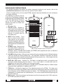
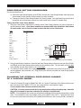
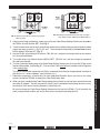
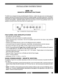
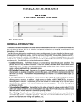
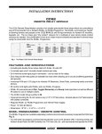
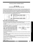
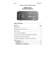
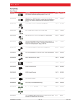
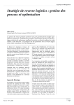
INSTALLATION INSTRUCTIONS RC68+ PROGRAMMER / REMOTE CONTROL The RC68+ programmer is a 55 key hand-held device that generates all the IR codes necessary for the set up and operation of Xantech IR remote controlled products. Such products include models ZPR68, RAT1, MIRV1, GATEKEEP-IR, etc. The RC68+ is an upgrade of the previous 32 key RC68. While providing additional key-code command capabilities, it retains all previous RC68 programming in a similar 32 key layout section on the keypad. A A B C ADJ-OFF 80 48 10 90 1 2 3 4 00 C0 50 6 INPUT 7 5 40 A0 01 D0 41 8 30 B0 21 61 GLOBAL GENERAL • The RC68+ is used initially for the setup of system control parameters and IR Code Groups for Xantech products. 20 E0 70 F0 TREBLE BASS Z-ADJ VOL 60 88 18 98 09 MUTE • It is then used to "teach" a basic set of operational IR commands into universal learning devices such as the Xantech URC series learning remotes, the Xantech Smart Pads, the 590 Programmable Controller, the 710 Fone Link, etc., for the end user. 08 A8 38 B8 ON OFF 28 E8 78 F8 E-FLAT LAST MAX-V TRIM 68 C8 58 D8 49 OFF 29 69 C-BAL E1 89 C9 A9 E9 71 19 59 39 79 F1 99 D9 B9 F9 • Included with the RC68+ is a set of keypad overlays. These overlays are marked with command names that apply to specific Xantech models. They are provided to make it easier for the installer when setting up the system. See Fig. 2 and the model listings below. • While the RC68+ will operate as a separate remote control, it is highly recommended it not be given to the final user for the following reasons: RC68+ PROGRAMMER • Since it includes special setup codes, the user may inadvertently alter the installer configurations. • Also, since the user will require IR commands from other brands of equipment to control the total system, in addition to those of the RC68+, all commands should be consolidated into one learning device, for ease of use. • Additional temporary overlays are included for use with Xantech models that differ greatly from the ZPR68. B 0 C ADJ-OFF OFF ON TGL MMT C OFF ON 1 TGL 2 MMT 3 OFF ON 5 1 • The overlays are simply placed over the RC68+ keys, as needed. Use the overlay that corresponds to the Xantech model or models you are working with, as listed below. Xantech Model 1 2 3 4 5 6 INPUT 7 8 2 3 OFF GLOBAL 4 TREBLE BASS Z-ADJ OFF VOL 5 OFF MUTE RC68+ Overlay Id Letter RAT1, MIRV1, ............................................ A 6 ON OFF MAX-V TRIM OFF 7 (permanently attached E-FLAT LAST OFF TGL 16 OFF ON TGL 2 10 9 OFF ON TGL 3 14 13 OFF ON TGL 4 GP-ON GP-OFF OFF ON TGL 5 ON TGL 6 OFF OFF RGC11, RP41AV, to the RC68+) Overlay Identification Letter B A A OFF 4 D MMT 7 8 TGL MMT 11 12 1ON TGL MMT ON OFF 15 16 2ON TGL MMT ON 1OFF ON 3ON MMT ON 4ON MMT ON 5ON C-BAL ON 7OFF 8 CD SEQL RANDOM 9 ALL ON/TOG OFF ON/TOG OPEN CLOSE ARTIST ATITLE NUMBER BZONE ON/TOG OFF ON/TOG LEFT C D RIGHT ENTER SELECT ON/TOG OFF ON/TOG E ON/TOG OFF ON/TOG Gatekeep-IR Modules ................................ E RC68+ PROGRAMMER SmartPad3 .................................................. I FIG. 2 Overlays for the RC68+ Programmer RC68+ OFF OFF OFF OFF OFF OFF F 680-10, 686-10, CC62 ............................... D IR-DC4 (RC68+ IR-to-RS232, Arrakis) ...... F OFF 1 CD 8 RT8, RT16-10 ............................................ C F 3 PLAY MMT I OPEN CLOSE 0 5 1STOP 4 6 TGL MMT ON/TOG OFF ON/TOG OPEN CLOSE 3OFF 2 8 3 7 9 PAUSE TGL MMT ON/TOG OFF ON/TOG OPEN CLOSE 4OFF TGL 2OFF 8 Permanently attached "A" Overlay. CLOSE 2 ON 7 AC2, CC12, SR21 ...................................... B CLOSE MMT OPEN 1 ON ON ZPR68-10 E 4 0 5 CD# TR# RESUME GP-ON ON/TOG OFF ON/TOG OPEN CLOSE 5OFF 6 7TR + DISC -- DISC + TR -GP-OFF ON/TOG OFF ON/TOG OPEN CLOSE 6OFF 6 RS41AV, ZPR68, MMT MMT OPEN 1 OFF Amplifiers & Preamplifiers THE RC68+ OVERLAY SYSTEM • The RC68+ base unit comes with a permanently attached keypad overlay (A) with lettering that identifies the commands for operation of the model ZPR68 and other models with similar commands. COMMAND DEFINITIONS • For detailed information that defines the button commands relating to each overlay, refer to the Installation Instructions that come with each specific Xantech model. • The only exception to this is for the model ZPR68; complete command definitions for it are included on the pages that follow. 1 1 18 17 A B C 80 48 10 16 15 2. ADJ-OFF button. Provides instant turnoff of the TRIM and ZADJ modes on the ZPR68. TRIM and Z-ADJ will also turn off automatically 10 seconds after the last button press. 14 ADJ-OFF 90 1 2 3 4 00 C0 50 D0 5 1. IR Emitter Lens. 40 6 INPUT 7 A0 01 41 3 8 30 B0 21 61 GLOBAL 20 E0 70 F0 TREBLE BASS Z-ADJ VOL 60 88 18 98 09 08 A8 38 B8 29 ON OFF 4 Rear 5 MUTE F8 TRIM 58 D8 49 C-BAL E1 89 C9 A9 E9 71 19 59 39 79 F1 99 D9 B9 F9 8 9 78 A 9 9 78 A 10 CODE GROUP 4 65 6 3 43 5 4 65 6 3 43 5 9 7 89 A 78 A DD E BC BC E 9 7 88 9 A 7 A F 012 F 012 12 F0 F 012 11 7 3456 OFF 69 3456 78 MAX-V C8 D BC E E8 LAST 68 D BC E 28 E-FLAT F 012 13 12 6 DD BC EE BC 3. INPUT Select buttons. Press these to select up to 8 audio/ video sources on the Xantech controlled unit (where applicable). Also, on the ZPR68, pressing any INPUT button turns the addressed zone ON. 2 A F 012 The following list itemizes and describes the full set of button commands for operation of the ZPR68 and ZPR6810 Six Zone Eight Source Preamp as well as the IR Code Group setting switches that affect all RC68+ controlled models. 19 Front 20 RC68+ PROGRAMMER 4. GLOBAL button. After pressing this button (within 5 seconds) all FIG. 3 RC68+ Itemized Functions and Features subsequent commands for the ZPR68 (i.e. INPUT, VOLUME, MUTE, BASS, and TREBLE) will be applied to all zones, in addition to the addressed zone, from any zone location. 5. VOLUME Up/Down buttons. When pressed, volume will increase and decrease in 2 dB steps between 0 dB and -80 dB (on remote preamps only. See applicable Installation Instructions for specific attenuation details when controlling remote autoformer volume controls, etc.). When buttons are held down, the volume level will change continuously. 6. MUTE ON / OFF buttons. Separate On / Off buttons, on applicable models, give positive mute commands without knowing what the status is. This is very helpful in a remote room when all adjustments are made “blind” without any visual aids for status. NOTE: Mute is released (turned off) when a VOLUME, INPUT, BALANCE, BASS or TREBLE button is pressed (where applicable), in addition to MUTE OFF. 7. TRIM button. Activates the Input Level Trim adjustment mode on the ZPR68. This allows level trimming of each input on the ZPR68 so that all sources will sound equally loud when switching from one to the other (see the ZPR68 instructions for details). The TRIM adjustment mode will turn off automatically 10 seconds after the last button press - or it can be instantly defeated by pressing the ADJ-OFF button (2). 8. MAX-V button. Saves the maximum desired volume level for the zone when in the Z-ADJ mode (see the ZPR68 instructions for details). 2 RC68+ 9. BALANCE buttons. When the BALANCE "arrow" buttons are pressed, the audio output will move to the left or right (with a 2 dB/step reduction in the attenuated channel) with each left or right press. NOTE: No change will occur if the BALANCE buttons are held down continuously! 10. Balance "Center" button. This button, when pressed (identified by a "—" mark), will instantly return the balance to the center position (equal volume in each channel) from any previous setting. 11. OFF button. Turns any zone on the ZPR68 OFF. The ZPR68, however, remains in "standby" mode, ready for zone turn-ON when any INPUT button is pressed. 12. LAST button. Returns to the last adjusted values on the ZPR68 when comparing customized tone and balance settings to electrical flat (E-FLAT). Refer to the ZPR68 instructions for details. 13. E-FLAT button. Switches the tone settings to electrical flat (flat frequency response) and the balance to center, from customized settings. In conjunction with the LAST button, it allows instant comparisons during setup procedures. Refer to the ZPR68 instructions for details. 14. TREBLE & BASS control buttons. When the "arrow" buttons are pressed, the treble and bass response can be increased or decreased from 0 dB to ± 12 dB in 2 dB steps with each up or down press. NOTE: No change will occur if the TREBLE & BASS buttons are held down continuously! Use these controls to "EQ" (equalize) the sound for each zone's acoustic differences during the "ZADJ" settings on the ZPR68. The values arrived at will become the "N-Flat" values (nominal or acoustic flat) for the user. 15. Treble & Bass "N-Flat" buttons. These buttons, when pressed (identified by a "—" mark), will instantly return the treble and bass to the "N-Flat" values (nominal or acoustic flat) from any previous settings the user may have made. 16. Z-ADJ button. Activates the ZONE ADJUSTMENTS mode on the ZPR68, allowing customized bass, treble, balance and maximum level settings for each individual zone. Z-ADJ will turn off automatically 10 seconds after the last button press - or it can be instantly defeated by pressing the ADJ-OFF button. Refer to the ZPR68 instructions for details. The RC68+ may also be used to change the Code Group Number within the Xantech model itself, so that it is different than the factory setting. This is necessary when two or more of the same Xantech model are used in the same IR system. See CODE GROUP SETTING PROCEDURES. 18. A, B, C buttons. These operate special control functions on certain Xantech products. See applicable model instructions for details. 19. Code Group Setting Switches. These rotary switches are for setting and selecting the specific IR Remote Control Code Group Numbers. See Code Group Setting Procedures. 20. Battery Compartment. Holds two 1.5V "AA" batteries that power the RC68+. Use Alkaline batteries for longest life. Slide cover in the direction of the arrow for removal. RC68+ 3 Amplifiers & Preamplifiers 17. Code Group Numbers. The front face of each button on the RC68+ is marked with a Code Group Number identifying a total of 55 different IR Remote Control Code Groups. You will need to change the Code Group Number on the RC68+ to match the Code Group Number factory set for each different Xantech model. CODE GROUP SETTING PROCEDURES Use these procedures to: a) Select the Code Group Number on the RC68+ to match the Code Group Number internally preset at the factory for the specific Xantech model you wish to control. b) Change the Internal Code Group Number of a Xantech model. You would do this to avoid mutual interaction when using two or more of the same model on the same IR network (bus). Setting the RC68+ Code Group Number 3456 9 78 A D BC E F 012 RC68+ (rear panel) 9 78 A D BC E F 012 CODE GROUP 3456 3456 F 012 1st Digit (Left) 9 78 A F 012 9 78 A D BC E ZPR68, ZPR68-10 Code Group Number 88 98 28 50 60 C8 D1, D2, D3 30 30 30 40 20 D8 50 58 70 D BC E Model 680-10 686-10 AC2 CC12 CC62 GATEKEEP-IR IR-DC4 MIRV1 RAT1 RGC11 RP41AV RS41AV SmartPad3 SR21 RT8 RT16-10 3456 1. Using the chart below, determine the factory preset Code Group Number you need to operate a specific Xantech model. Since these numbers are also provided in the Installation Instructions for each model, refer to them for newer models that may not be listed below. 2nd Digit (Right) 68 FIG. 4 Setting the code switches (68 shown for the ZPR68) 2. Using a small blade screwdriver, rotate the two Code Group setting switches on the rear of the RC68+ (see Fig. 4) to the Code Group number noted from the previous chart. The Left switch is the first digit in the number and the Right switch is the second digit. 3. The Xantech model should now respond to the RC68+ commands that relate to that device (i.e., volume up/down, input selection, etc.). Fig. 4 shows the switches set to 68, the Code Group number for the ZPR68. CHANGING THE INTERNAL CODE GROUP NUMBER OF A XANTECH MODEL 1. Connect a Xantech IR receiver (Model 780, 480, etc.) to the IR terminals of the Xantech device you wish to change (RAT1/MIRV1, RT16-10, etc.) along with the correct power supply. Do not connect other Xantech models at this time. CAUTION: You must connect each device separately when setting the code group, otherwise they will all respond to the same code after the change is implemented! NOTE: The exception to this is when you intentionally want two or more units to respond to the same code. This would be the case, for example, when using a MIRV1 with a RAT1. These two units must be set to the same code so that they will respond to each other as well as to the RC68+ commands. 4 RC68+ 3456 3456 3456 3456 3456 F 012 F 012 3456 F 012 3456 F 012 F 012 3456 F 012 F 012 FIG. 5 Switches set to FF for Code Group changes. Refer to step 2. 9 78 A D BC E 1st Digit (Left) 2nd Digit (Right) D BC E 9 78 A 9 78 A D BC E D BC E 1st Digit (Left) F 012 CODE GROUP CODE GROUP 9 78 A 9 78 A D BC E RC68+ (rear panel) 9 78 A D BC E 9 78 A D BC E D BC E RC68+ (rear panel) 9 78 A 2nd Digit (Right) FIG. 6 Setting the code switches to the newly changed code. Refer to step 6. (30 shown for MIRV1/RAT1). 2. Using a small blade screwdriver, rotate each of the two Code Group Setting Switches on the rear of the RC68+ to the F position (FF). See Fig. 5. 3. Turn the remote over and locate a Code Group number that is different than any other Xantech model used in the same system (i.e., 48, D0, C0, etc.). These numbers are printed on the front face of each RC68+ button! (See item #17, Fig. 3). 4. Aim the RC68+ at the Xantech IR receiver (780, 480, etc.) and press the button that has the number on it that you decided on. 5. The control chip in the Xantech device (MIRV1/RAT1, RS41AV, etc.) will now change to respond to the code you selected. 6. Test the system by rotating each of the Code Group Setting Switches on the rear of the RC68+ to the chosen code number (refer to Fig. 6). The Left switch is the first digit in the number and the Right one is the second digit. The device should now respond to the RC68+ commands that relate to the operational functions of that device (i.e., volume up/down, input selection, etc.). 7. Repeat this procedure, as necessary, for each duplicated Xantech device you have in the same system (except the ZPR68), changing the Code Group each time. Be sure to change the Code Group Setting Switches on the rear of the RC68+ (Fig. 6) to match the newly changed code number you set for each device, during the teaching process. 8-28-00 RC68+ 5 Amplifiers & Preamplifiers 8. When you have completed the Code Group settings for each device, you may then connect them into the same IR network. You will now need to "teach" these commands into learning devices such as the Xantech URC series Learning Remotes, SmartPads, etc.