1
Manual
Data Retrieval, Processing and
Final Storage into the Nile Basin Database
Entebbe October 2001
NILE BASIN INITIATIVE
Initiative du Bassin du Nil
Information Products for Nile Basin Water Resources Management
www.fao.org/nr/water/faonile
The designations employed and the presentation of material
throughout this book do not imply the expression of any opinion
whatsoever on the part of the Food and Agriculture Organization
(FAO) concerning the legal or development status of any country,
territory, city, or area or of its authorities, or concerning the
delimitations of its frontiers or boundaries.
The authors are responsible for the choice and the presentation
of the facts contained in this book and for the opinions expressed
therein, which are not necessarily those of FAO and do not commit
the Organization.
© FAO 2011
Table of Contents
Table of Contents
1
Introduction
9
1.1
General
9
1.2
Overview of the Contents of the Manual
9
2
Detailed Outline of the Data Trajectory
11
2.1
General
11
2.2
Hardware
11
2.3
Software
12
2.4
Comprehensive Data Trajectory
13
3
Installation of the Remaining Hardware and Software
15
3.1
Installation of SC532-A Interface
15
3.2
Installation of PC208W Datalogger Support Software
15
4
Recommended Folder (Directory) Structure
16
4.1
General
16
4.2
PC208W Files
16
4.3
MS Access Database Files
17
5
PC208W Datalogger Support Software
19
5.1
Introduction
19
5.2
StgModule Component
19
5.3
5.2.1
5.2.2
5.2.3
5.2.4
5.2.5
5.2.6
Introduction
Connecting Storage Module to PC
Retrieving Raw Data Files from Storage Module
Pointers
Erasing Data on the Storage Module
Trouble Shooting
Report Utility of the PC208W 3.3 Software
5.3.1
26
Introduction
Manual
3
Table of Contents
5.3.2
4
Processing Data from Met Station
5.3.2.1 General
5.3.2.2 Five-Minute Rainfall Data
5.3.2.3 Hourly Meteorological Time Series
5.3.2.4 Daily Meteorological Time Series
5.3.2.5 Meteorological Station Performance Information
5.3.2.6 Renaming Meteorological Output Files
6
Data Processing in MS Access and Final Storage into the NBD
39
6.1
General
39
6.2
MS Access Database “NBD NEW DATA”
39
6.3
Importing Output ASCII Text Files Generated by Report into MS Access
41
6.4
Processing of Imported Data in MS Access and Final Transfer into the NBD
47
6.5
Transfer of Raw Input and Report Output Files into Backup Folder
51
7
Exchange of NBD Data with Other Users
52
7.1
Problem Description
52
7.2
Preparation of Transfer Files
52
Data Retrieval, Processing and Final Storage in the Nile Basin Database
List of Figures
List of Figures
Figure 1:
Figure 2:
Figure 3:
Figure 4:
Figure 5:
Hardware components involved in data acquisition process
Software components and file formats involved in data acquisition
and storage process
Recommended directory structure for PC208W and related “work” files
Required Folder (Directory) structure for all MS Access database files
Final data processing steps in MS Access and subsequent removal and
storage of raw files as backups
11
12
16
17
39
Manual
5
List of Tables
List of Tables
Table 1:
Table 2:
Table 3:
Table 4:
6
Comprehensive Data Trajectory
Various Files and their Function Used by Report in the Processing of
Meteo Station Measurements
Database Objects and their Function in the MS Access Database file
”NBD_Pre Processing.mdb”
Designated Input and Destination Tables for each Pre-defined Append Query
Data Retrieval, Processing and Final Storage in the Nile Basin Database
14
27
40
48
Annexes
Annexes
Annex 1:
Annex 2:
Annex 3:
Annex 4:
Annex 5:
Annex 6:
Consecutive Steps in Connecting Storage Module SM4M/SM192 to PC.
Consecutive Steps in Retrieving Raw Data Files form SM4M/SM192 Storage Module to PC.
Consecutive Steps in Processing Raw Data Files in Report.
Consecutive Steps in Pre-Processing of Report Output Files in MS Access and Appending
Processed New Data Sets into NBD.
General Design of the Append Queries for Pre-Processing of the Report Output Files in MS Access.
Design of the ID Converter Table.
Manual
7
Foreword
Foreword
FAO regional project GCP/INT/752/ITA – Nile Basin Water Resources is committed in establishing a limited water
resources monitoring network in the Nile Basin region. The adopted monitoring network consists of 21 meteorological
and 14 hydrological stations to be either rehabilitated or newly implemented at key points in the Nile Basin. These
stations will be supplied with conventional and/or fully automatic equipment depending upon the priorities of the
hydrometeorological departments in the respective beneficiary countries. This network is a continuation of the efforts
made by the previously concluded FAO Lake Victoria Water Resources Project, which has already established, fully
automatic 14 hydrological and 4 meteorological stations in the Lake Victoria region of the Nile Basin. The network is
no doubt inadequate as compared to the identified needs and water resources development priorities in the region.
The beneficiary countries have placed, with slight variation an emphasis and scope, a high priority on sustainable
and environmentally sound water resources development in the Nile Basin region to satisfy rapidly increasing water
demand for irrigation to increase food production, hydropower production and domestic and industrial water supply.
For this reason, substantial additional efforts and resources will be necessary to address the remaining gaps in the
environmental and water resources data and information by expanding further the monitoring network and georeferenced database system established by the FAO Projects in the region.
Recognizing the importance of the established nucleus monitoring network in this context, the project is making
every effort to secure its sustainable and technically sound operation and maintenance, as well as collection of data
from the network, data quality control, processing and final storage into the Nile Basin database. To this effect most
of the stations in the adopted network are being furnished with state of the art data loggers and hydrometeorological
measuring sensors which require minimum efforts and material for operation and maintenance. It is important to
mention that the experience gained from the automatic equipment installed by the concluded Project have been
proved, now for years, to be successful. Furthermore the project is developing a series of technical manuals and
conducting comprehensive on-the-job training seminars and workshops in the region on all aspects of equipment
installation, station operation and maintenance and data processing.
The Manual on Data Retrieval, Processing and Final Storage into the Nile Basin Databases is the latest in the
series. Its first version was written in January 99 during the previously concluded FAO GCP/RAF/304/JPN and has
now been revised due to the rapidly changing technology in its hardware and software installed in the Nile Basin. The
manual, at present, has also been subsequently used for training of national professionals in Rwanda, Kenya and
Uganda and is expected to be used for training of national professionals in other countries. The experience gained
during these practical training sessions was used to substantially simplify and improve many of the procedures
in this revised version of the manual. The project is thankful to all the trainees in the region for their enthusiastic
participation in the training sessions conducted so far and the extraordinary efforts in mastering the technology.
Based on evaluation of skills and know-how already in place in 4 countries of the region in this field we are confident
that the revised Manual presented hereby will further contribute towards the achievement of the major goal: the
sustainable and technically sound operation and maintenance of the monitoring network established by the Project
in the region, including the collection, quality control and processing of data generated in the network.
Dr. Mohammad Chebane
Chief Technical Advisor
October 2001, Entebbe, Uganda
8
Data Retrieval, Processing and Final Storage in the Nile Basin Database
Introduction
Introduction
1.1
General
The adopted Monitoring Network in the Nile Basin comprises of Automatic Hydrological and Meteorological Stations
equipped with electronic instruments for data acquisition and storage. Measurements are initially pre-processed
and stored on site in a digital storage and control module, commonly referred to as datalogger.
Periodically, the accumulated raw data are transferred from datalogger to a computer at the office of the hydrometeorological service. This is accomplished with the help of a portable data retrieval unit, which can serve several
stations during a single inspection tour. In order to enhance sustainability of the network, a visiting frequency of 1
month is proposed. Consequently, data should arrive at the office of the hydro-meteorological service with a delay
of maximum one month.
After transfer of the collected hydro-meteorological information from retrieval unit to PC, the newly imported data
should be processed, checked on consistency and possible measurement errors, and stored in a dedicated table in
the Nile Basin Database (NBD), regarded as their final destination.
The first segment of the data trajectory, i.e. transfer of measurements form logger to retrieval unit, is covered in
the manual “Manual for Installation, Operation and Maintenance of Automatic Meteorological Stations”.
The second part of the data trajectory is dealt with in this manual. It describes in detail all steps involved in
transferring the accumulated climatological measurements from the storage module to PC, processing of data
downloaded onto PC and final storage of the processed time series to the Nile Basin Database [NBD] in MS Access.
More specifically, this manual deals with the procedures for:
•
•
•
•
•
installation and setup of necessary hardware components;
transfer of raw data from storage module to PC in the initial data and file formats;
separation of individual measured variables from initial data file to comma separated ASCII file, and first visual
data quality check;
importing the pre-processed ASCII data file into MS Access;rearrangement of newly imported data to final
table structure using pre-defined database queries and second computer operated quality check;
appending and final storage of new data into the Nile Basin Database.
This manual deals with data originating from Campbell type Automatic Weather Stations (AWS). A substantial
number of steps involved in the data trajectory are included in the manual for processing actions.
1.2
Overview of the Contents of the Manual
This manual describes in detail all steps and operations involved in transferring the accumulated raw data from
retrieval unit to PC and primary processing – by using a Campbell Scientific software package, called PC208W, which
has been specifically tailored for the purpose; and secondary processing of pre-processed data and their subsequent
final storage into the NBD – by using MS Access database package.
In order to provide the user with the complete picture of the information flow from sensor to database, chapter 2
presents a detailed outline of the comprehensive data trajectory, as well as all software and hardware components
involved, and their role.
Chapter 3 concentrates on the instructions for installing the necessary hardware and software components that
are to be set up in appropriate manner.
Chapter 4 is discussing a recommended or required directory structure aimed at achieving uniformity in the
Manual
9
Introduction
location of the concerned files on the PC’s hard disk drive.
Chapter 5 deals in detail with retrieving the raw data from the storage module to PC, and the initial processing and
storing this new information into a file in a comma separated ASCII format for each strictly defined group of data.
Chapter 6 presents the instructions for importing the pre-processed new data set into MS Access, performing a
final processing round and storing the new data records into their final destination in the NBD.
Finally, chapter 7 describes the procedures for creating an MS Access “transfer” database file, extraction of
needed data records from any main NBD file/table and their storage into the ‘transfer’ file; this will enable the users
to disseminate the selected data records from NBD to other users, within the country of in the Nile Basin region, in
an easy manner and without violating the integrity of either new or historical data stored in the main NBD.
10
Data Retrieval, Processing and Final Storage in the Nile Basin Database
Detailed Outline of Data Trajectory
Detailed Outline of Data Trajectory
2.1
General
2.2
Hardware
This chapter gives an overview of the complete data trajectory, starting from values measured by the station’s sensor all the way till the final storage of data into the Nile Basin Database (NBD) on PC at the FPI. It presents the various hardware and software components involved in this process, together with their interconnection. Furthermore,
it lists sequentially all user actions that play a role in the data trajectory.
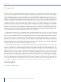
Figure 1 presents all hardware components involved in the route from sensor to PC in the hydro-meteorological data
acquisition process
Sensors
Datalogger
Keyboard Display or
Short Haul Modems
Storage Module
or Short Haul
Modems
SC532A/SC932
Interface
PC
Figure 1: Hardware components involved in data acquisition process.
The various climatological parameters are measured using electronic sensors. Depending on the nature of a
parameter, its value is represented by either a voltage or a sum of pulses.
The datalogger measures the voltages and/or counts the pulses, and transfers them to intelligible figures in
standard units, like for example degrees Celsius for temperature or mm of rainfall for precipitation. Other tasks
of the datalogger are to activate the various sensors at pre-defined intervals, and store the measurements in its
memory.
The CR10KD keyboard display is used to communicate with the datalogger on site. For instance, in case when a
user wants to invoke manual data transfer or check on operation of individual sensors, this is accomplished by connecting the CR10KD keyboard to storage module and logger, and by typing in on the keyboard the proper commands.
Also, when the user wants to check the performance of sensors and datalogger while onsite, this is achieved by
connecting the keyboard only to the datalogger and keying in the respective commands.
The SM4M/SM192 storage module is used to download the accumulated raw data from datalogger on site and
Manual
11
Detailed Outline of Data Trajectory
thereafter to transfer/upload the raw data to the Personal Computer at the office. Information is stored in the module
in a specific format, which cannot be read directly by IBM compatible PCs.
The role of the SC532A or SC932 Interface is, therefore, to convert this specific storage module format into a RS232 compatible
information communication standard, which is ‘understood’ by IBM compatible PCs.
Data can also be downloaded directly from the meteorological station to the PC using short haul modems without using keyboard and storage module.
Data pre-processing, processing final check and storage in the NBD is accomplished on PC.
2.3
Software
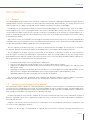
Figure 2 presents the various software packages and programs, as well as the concerned file formats, which are
used in the process of data acquisition, pre-processing, processing and final storage.
Data processing, rearrangement and final storage in the LVBD is accomplished on PC.
-Campbell Scientific Datalogger
Operating System
-METSTAT or
HYDROSTN Datalogger
Program
StgModule Component of
Campbell Scientific Software
Package – PC208W
Unprocessed batch
data files in a specific
Campbell Scientific
format
Retrieved unprocessed
batch data stored in
ASCII file format
Report/Split Component of
Campbell Scientific Software
Package – PC208W
MS Access Database
Software Package
Preprocessed data files
for each predefined
data group stored in
comma separated
ASCII file format
Final Storage of Processed
Data into NBD in Standard
Database Format
Figure 2: Software components and file formats involved in data acquisition and storage process.
12
Data Retrieval, Processing and Final Storage in the Nile Basin Database
Detailed Outline of Data Trajectory
The datalogger works under a specific Campbell Scientific operating system and is controlled by the METSTAT
datalogger program for meteorological stations. These programs are specifically created by the project GCP/INT/752/
ITA – Nile Basin Water Resources for the sensor configuration and data requirements in the network established by
the project. The datalogger program has been tested extensively by the project specialists, proved to work properly
and require no further user intervention.
As indicated in paragraph 2.2, data is transferred from datalogger to PC with help of the SM4M/SM192 storage
module. These modules use a specific Campbell Scientific data format, which is highly condensed in order to make
optimal use of its memory.
Once the observed data are downloaded to the storage module, the next steps are performed by using PC208W
Datalogger Support Software. This is a special software package developed by Campbell Scientific for communication
between datalogger and PC. It consists of 8 modules of which only two are of interest for handling meteorological
data measured in the network established by the project in the Nile Basin.
The StgModule component of the software retrieves files from the SM4M or SM192 Storage Module into ASCII files
on PC without any modification of the original data structure and sequence stored in the storage module.
The Report component, often referred to as Split, is used to split, restructure and separate these ASCII files
according to the required file/table structure of the user, transfer the dates from Julian format to corresponding
months and days, and store the resulting data groups into a comma separated ASCII file. The latter format is
preferred for subsequent import of external data into MS Access.
Final data processing is accomplished by using MS Access database software package through several predefined database tables and queries; the tables and queries have been specifically tailored for final processing of
meteorological data observed in the network established by the project. Lastly, the processed data are appended and
finally stored into the appropriate tables in the MS Access based Nile Basin Database.
2.4
Comprehensive Data Trajectory
In order to arrive at a complete understanding of interconnections between the various hardware and software
elements that play a role in the data flow, table 1 presents a comprehensive overview of the entire data trajectory
- from initial measurement to final dissemination. It shows the place and function of the respective hardware and
software items and their interrelation. Furthermore, it lists in a sequential order all necessary user actions.
All the actions described in table 1 are covered in this manual except for those indicated under the 1, 2 and 8. These
three actions are included into the table for user’s benefit of having better insight into the whole data trajectory –
starting from its onsite measurement by a sensor and ending up with the use of stored data for various types of
water resources analysis, studies and modeling. The procedures concerned with actions 1 and 2 are covered in the
respective operation and installation manuals specifically concerned with Automatic Weather Stations established
within the project. The action refers to a broad range of applications in water resources analysis and modeling
which are described elsewhere, including a series of training notes for data processing and analysis within the georeferenced database as well as The Nile Basin Decision Support Tool manuals and software packages developed
under the project.
Consequently, as already indicated in paragraph 1.1, this manual covers in detail the actions 3 to 7 given in table
1.
Manual
13
Detailed Outline of Data Trajectory
Table 1: Comprehensive Data Trajectory
Step
1
Operation
~ Periodic automatic measurement of
meteorological parameters
~ pre-processing and storage in the
datalogger’s RAM
~ Transfer of accumulated
measurements from logger’s RAM to
portable SM4M/SM192 Storage
Module; each single transfer exercise
results in a separate data file
Hardware Involved
~ Sensors
~ Datalogger
Software Involved
~ Campbell Scientific Datalogger
Operating System (OS)
~ METSTAT datalogger program
User Action
~ None
~ Datalogger
~ SM4M/SM192
Storage Module
~ CR10KD Keyboard
Display
~ Campbell Scientific Datalogger
Operating System (OS)
~ METSTAT datalogger program
~ Connect SM4M to datalogger
~ Type in proper keyboard
commands
3
~ Transfer of data files from SM4M or
SM192 Storage Module to PC
~ SM4M/SM192
Storage Module
~ SC532A Interface
~ PC
StgModule component of
PC208W datalogger support
software
4
~ Separating and/or rearranging
individual meteorological parameters
from a complete, original data file
~ PC
~ Report (Split) component of
PC208W datalogger support
software
5
~ Exporting separated/rearranged
~ PC
meteorological parameters to comma
separated ASCII file
~ Report (Split) component of
PC208W datalogger support
software
6
~ Importing comma separated ASCII
file into MS Access and restructuring
data to NBD format
~ Initial (automatic) quality control
~ PC
~ MS Access
~ (predefined tables in NBD
NEW DATA folder)
7
~ Final Storage in the NBD
~ PC
8
~ Further quality control, dissemination ~ PC
and use of data stored in the NBD
(described elsewhere)
~ MS Access
~ (predefined tables and queries
in NBD NEW DATA folder)
~ MS Access
~ (NBD folder)
2
14
Data Retrieval, Processing and Final Storage in the Nile Basin Database
The user can choose between
automatic or manually invoked data
transfer
~ Connect SM4M/SM192 to SC532
~ Activate StgModule Software
~ Establish connection between PC
and SM4M/SM 192
~ Invoke data transfer
~ Activate Report software
~ Open appropriate pre-defined
parameter file
~ Select input data file
~ Run Split
~ First, visual data quality check
~ Activate Report software
~ Open appropriate pre-defined
parameter file
~ Select input data file
~ Select and define output data file
~ Run Split
~ Activate MS Access
~ Open appropriate database file
~ Import ASCII file in predefined
table
~ Final check of data and
corrections
~ Activate predefined query to
restructure data format and finally
store/append data into NBD.
~ Open ap propriate NBD file
~ Open appropriate table
~ Export data into desired
application program or file for
further analysis or data
dissemination (see chapter 7)
Hardware and Software Installation
Installation of the remaining Hardware and
Software
3.1
Installation of SC532A Interface
Provided a PC has already been set up successfully, only one hardware item remains to be installed: the SC532A
Interface. The function of this interface is to connect IBM compatible computers to the SM4M or SM192 storage
module and convert their contents into RS232 format, or more precisely into a standard RS232 data transfer protocol,
which is well understood by any IBM compatible personal computer.
In case the short haul modems are used for on line data collection, the SC932 Interface is connected permanently
and therefore the use of SC532 Interface should be avoided.
The SC532A has a 9-pin connector for linkage with the storage module and uses a 9-pin connector to connect the
interface to a 9-pin serial port at the PC. The SC532A interface is powered by an AC adapter. Both the 9-pin female
connecting ends of the SC532A interface are identical therefore care should be taken that its “PC” labeled end should
be connected to the serial port at the PC and that the “PERIPHERAL” labeled end is connected to the SM4M storage
module.
Installation of the SC532A Interface is a straight forward process. Connect the SC532A to PC using the supplied ‘9
to 9 pin’ computer cable. The 9-pin female end of the cable should be connected to the PC’s serial port 1 or 2, while
the other 9-pin male end of the cable is to be plugged into the SC532A.
Connect the other 9-pin female end of the SC532A interface to the SM4M Storage Module using the blue, specific
Campbell Scientific SC12 storage module cable.
Since the SC532 Interface runs on 110V, use a 220 - 110 transformer between mains and the SC532A while in East
Africa.
All hardware components are now installed. Make sure power is supplied to the SC532.
Note: The old model SC532 Interface has 25-pin connector while the other end has a 9-pin connector and therefore
using a 25 to 9-pin computer cable. This information is for the users in Kenya, Uganda and Tanzania.
3.2
Installation of PC208W Datalogger Support Software
PC208W 3.3 Datalogger Support Software requires Windows 95 or higher. There needs to be at least 10Mb of free
hard disk space for software installation.
Insert the PC208W CD in drive D. It will install automatically by following the instructions on the screen. Otherwise
in Windows 95 (or above), select RUN from the Start button. Type in A:\SETUP and click the OK button. Follow the
instructions given on the screen.
It is recommended to use the following Working Directory name: C:/CAMPBELL/PC208W.
Manual
15
Recommended Directory Structure
Recommended Directory Structure
4.1
General
4.2
PC208W Files
For standardization and instruction purposes, this chapter proposes a Recommended Folder (Directory) Structure.
The user is free to modify this if another system would better suits his or her particular computer organization.
However, the instructions presented in this manual are based on the proposed structure. Modification of it will
require corresponding adjustment of commands concerning file locations.
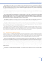
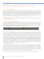
Figure 3 presents the Recommended Directory Structure for all files related to PC208W Datalogger Support
Software. A subdivision has been made between the PC208W program files and the ones actually used in the data
processing, the ‘work’ files.
C
Campbell
Files
PC208W
Backup
Input
Output
Parametr
Figure 3: Recommended Directory Structure for PC208W and related ‘work’ files.
The above Folder (Directory Structure required the creation of a main folder called CAMPBELL on the C drive. The
Campbell Folder consists of two sub-folders named FILES and PC208W. The datalogger support software PC208W
should be installed in the latter one, see paragraph 3.2.
The FILES folder is sub-divided into four folders: INPUT, OUTPUT, PARAMETER and BACKUP.
The INPUT sub-folder is destined for all data files retrieved from the SM4M/SM192 storage module or directly from
the datalogger using short haul modems. By default these files are given a DAT extension.
The OUTPUT sub-folder is allocated for all processed, comma separated ASCII files, with TXT extension. They
result from the separation and file restructuring exercise in Report (a.k.a. Split).
The PARAMETR sub-folder is used to store all predefined Split files, having a PAR extension.
The BACKUP sub-folder is used to temporarily store the files once they have been converted and processed in
MS Access. Use of the above mentioned files is discussed in more detail in chapter 5. The proposed structure is
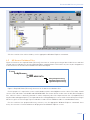
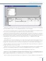
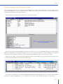
illustrated in the following Windows Explorer screen.
16
Data Retrieval, Processing and Final Storage in the Nile Basin Database
Recommended Directory Structure
E xploring - Campbell
View
Edit
File
Go
Favorites
t
Foird
Back
Address
Up
Tools
y
Cut
iff
Help
Copy
Paste
Delete
Properties
CACampbell
411111.1111
Folders
Floppy
x
A.
I Name
Size
Type
File Folder
1:11 Files
File Folder
P.1=0 (C:)
A.crobat3
uackup
ti
Campbell
MINN
1
Backup
Iriput
Output
-Li' Parameter
Pc21:18w
Lc
V
udr orn
2 object(s)
4
0 bytes (D isk free space: 3.356E I
My Computer
*For the creation of the various folders, use the appropriate Windows Explorer commands.
4.3
MS Access Database Files
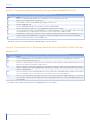
Figure 4 illustrates the required Folder (Directory) Structure for further processing of data in MS Access and final
storage of processed data files into the NBD in database standard format. This format can, later on, be changed once
a final structure for the Nile Basin Database has been developed.
C:
MyDbase
NBD
NBD NEW DATA
Kenya Preprocessing
Rwanda Preprocessing
Uganda Preprocessing
Figure 4: Required Folder (Directory) Structure for all MS Access database files.
For this purpose it is required to create a main database folder called MyDbase on the C drive. This folder should
consist of two sub-folders called NBD and NBD NEW DATA. The former will be used to store the Nile Basin Database
files, while the latter is basically planned to contain temporary data files imported from the C:/Campbell/Files/
Output folder and append queries; the imported dta files and append queries are used for further data processing in
MS Access, prior to final storage of processed data records into the NBD data tables in standard data format.
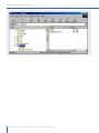
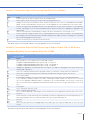
For the creation of the proposed directory structure, use the appropriate Windows Explorer commands. Once
more, the structure is illustrated below as displayed on the Windows Explorer screen:
Manual
17
Recommended Directory Structure
1111 Exploring
Edit
File
HyD baso
View
,
Back
.1
G
Favorie
F
.
ocl
Herp
yr)
.
Up
Cut
73
Paste
Copy
I
2')
'
Lindo
D,E4ete
Properties
Address Iù C:\ MjDbase
Name
IFolders
Carnpbel
II
Size t TIpe
LL1 N td
File Fcitier
rf_l NED N Dyq DATA
File FcidEff
jJ Pc2CIDAI
Di ro rn
p..111 D1.7.1
8..L1 Esri
Ki-lan
1
.es) M9 Document':
1=1..)
12121212
N bi
l33.-Li NED NEW DATA
12 cUrct(sil
18
1
4
I
lO bytes ÍDik hot spoce...: 9.34GEIA My Cb-rputtr
Data Retrieval, Processing and Final Storage in the Nile Basin Database
I_
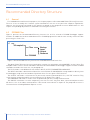
PC208W Datalogger Support Software
PC208W Datalogger Support Software
5.1
Introduction
PC208W Datalogger Support Software is a Windows based software package specifically developed by Campbell
Scientific for communication between datalogger and PC. It consists of a help module and 7 independent datalogger
support components. Among them are also the utilities for setting up a network of PC connected stations and on-line
datalogger communication. Depending on the conditions and requirements these utilities will not be used in certain
cases whereas in other cases these may be used wherever feasible in the Basin. For example the Project may
consider the option of direct on-line communication with the stations using short haul modems or cellular mobile
communications.
Smooth flow of data from datalogger to Nile Basin Database is accomplished with the help of the following three
PC208W utilities: Connect, StgModule and Report. The first and second serve to transfer raw data files either directly
from the datalogger to the PC via short haul modems or then from storage module to PC, while the second is used
to separate the various meteorological variables from raw batch data transferred from the datalogger or storage
module into PC, and re-arrange their data structure.
These software utilities will be discussed in the paragraphs given below. However, the text that follows does
not cover all aspects of the two PC208W software utilities. Only the subjects which are considered important and
essential in the data downloading process are discussed. The user is referred to the respective Campbell Scientific
Instruction Manuals, as well as the on-line help, in case of need for more information. The use of “Connect” utility
is still under experiment at the Project office and will be included in the manual later on.
5.2
StgModule Component
5.2.1 Introduction
Due to recent rapid developments in the mobile/cellular telecommunications in most of the African countries, it
has become feasible to establish on-line communication between a datalogger and a PC. The Project experts are
exploring ways for making it possible to transfer on-line digital data from a remotely stationed datalogger to the PC
using a cellular communication facility. Apart from this, the project has also opted for the portable SM4M or SM192
Storage Module to transfer the accumulated raw data from the logger’s RAM to personal computer. This storage
device can contain up to almost 400,000 data values as well as a maximum of 8 datalogger programs. Communication
between storage module and PC is enabled through the StgModule software, discussed in this paragraph.
5.2.2 Connecting Storage Module to PC
This paragraph presents the instructions for establishing communication between SM4M or SM192 and PC.
Step A1: Connect the SM4M/SM192 Storage Module to the SC532A Interface using the blue SC12 cable.
Step A2: Make sure the SC532A Interface is powered.
Step A3: Double click the PC208W Datalogger Support Software Icon, presented below.
Manual
19
PC208W Datalogger Support Software
The following toolbar appears:
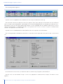
Step A4: Click the StgModule tab. A window alike the one presented below shows up.
The menu-bar contains five different items: File, Options, Data, Tools and Help. Just beneath this line 4 different
tabs are found, named CSM1/MCR1, SM192/SM716, PCCard and SM4M/SM16M, each dealing with a different storage medium. Since the Nile Basin Monitoring Network is either equipped with the SM4M or SM192 unit, click the
required SM192/SM716 or SM4M/SM16M tab at the top-mid of the screen to activate its specific communication
software. Disregard the other three tabs.
Step A5: Click the SM4M/SM16M or SM192/SM716 tab at the top-mid of the SMS window.
The resulting window is divided into two halves: a status box on the right and a task specific sub- screen on the
left.
SMS
File
Options
Data
Tools
Help
GSM-I/MC:RI
PC Card 11
S M192./5 ty17-113
SM4M/S141614:
F-StatusBox
Module Pointers
Free Space
- Programs
Program Status
I
Storage Ref F'ointer
Display Pointer
DumpPointer
Prog
r Frog 2
F'rog 3
Prog 4
Prog 5
Prog 6
F-Module Values
Good FLASH blocks
Error Count
Programs
r Frog 7
Prog 8
Switch Settings
Clear
Store
Read
StatusAdvanced...!
\Setup ,l'i,Progran-isADataii,Erasei
I4 Connect
Update Status
I
At the bottom-left of the latter, four different tabs are found: Setup, Programs, Data and Erase.
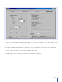
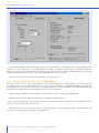
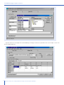
Step A6: Click the tab labeled ‘Setup’ to select the appropriate communication settings. The below screen
appears.
20
Data Retrieval, Processing and Final Storage in the Nile Basin Database
PC208W Datalogger Support Software
SMS
File
Data
Options
Tools
Help
5M192/Sty171
csk.11.4.1C:R1
SM4M1SM161.11
F'C C:ard
StatusBox
Module Pointers
FCOM Port Setup
I
Free Space
port
CONell
Baud Pate
COM2
',-52UU
MI"
COM3
C COM4
EVialcplox
Target Address
C
(-6
(11
(-4
c-7
Setup!, F'rograms
r5
Dat.
Module Values
Good FLASH blocks
Error Count
Programs
Switch Settings
(-k
C2
Storage Ref Pointer
Display Pointer
DumpPointer
r ad/MIL
EraeJ
L
7Status Advanced...!
* Connect
I
Update Status
I
Abort
I
Step A7: Select the COM Port settings corresponding to the serial port used by the “9 to 9 pin” computer cable
connecting the SC532A Interface (see paragraph 3.1). In most cases this will be either COM1 or COM2.
Step A8: Set Baud Rate at 19200. This is a measure of the communication speed between PC and Storage Module. In
case frequent communication problems are experienced, lower the Baud Rate and see if this solves the problem.
Step A9: Click the “Connect” button to connect SM4M or SM192 to PC.
If communication is successfully established, a window similar to the one below appears. Note that the status box
is no longer empty and is now containing information on the module’s memory.
Manual
21
PC208W Datalogger Support Software
SMS
File
Data
Options
Tools
Help
SM4M/SM16M
F'C Card
tyil 92/5 tyi 71 IS
/tyi CFI 1
CS tyi
StatusBox
Module Pointers
Free :pace
COM Port Setup
P 0 rt
0M1
Baud Pate
COM2
1j
Y11_11_1
COM3
2069180
Storage Ref. Pointer
Display Pointer
DumpPointer
27841
2
25446
Module Values
Good FLASH blocks
Error Count
Programs
COM4
64
o
2
E Via 1 f plox
Target Address
CA
1
2
(3
(4
r Switch Settings
r
76800/9600 Baud
Ring Mode
Address 1
(-7
5
CO
5tatusAAd.....anced...
Setupl,Prograrn::: D ata
E rase /
Disconnect
I
Update Status
I
@I /abort
1
_M_
PC and Storage Module are now connected. The user can proceed with retrieving data files or other SM4M related
operations. If the connection is not established successfully, a message will pop up as “Standard Prompt Not
Detected”. Recheck the wiring connection and make sure that the Interface and the Storage Module are connected
properly to the power source. Also recheck the COM PORT and then try to connect.
For ease of reference, the above-presented steps are listed in Annex 1.
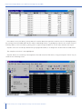
5.2.3 Retrieving Raw Data Files from Storage Module
During each data transfer from the datalogger to the storage module, the storage module stores this new data
as a separate file. The storage module gives it automatically a new name or it could be changed as desired. This
paragraph presents the user instructions for retrieving raw data files from the SM4M or SM192 Storage Module and
storing them at a desired location (folder/directory) on the PC’s hard drive.
Step B1: Connect SM4M to PC and establish communication. See instructions in paragraph 5.2.2.
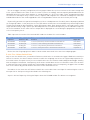
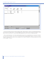
Step B2: Click the “Data” tab at the bottom-left. The below window appears.
Note that switching between the various task-specific sub screens (Setup, Programs, Data and Erase) has no
influence on the contents of the Status Box.
Step B3: Mark the “Comma separated” option in the File Format select box. Import of comma separated ASCII files
into MS Access has proven to be flawless and trouble free.
22
Data Retrieval, Processing and Final Storage in the Nile Basin Database
PC208W Datalogger Support Software
rI
SMS
File
_Options
Data
Tools
Help
.SM1S2/9ty1716
CStyl1/MCR1
File Format
Status E;
Module Pointers
C ornma separat e d
Free Space
Storage Ref. Pointer
Display Pointer
DumpPointer
r ASCII with Arra.,.. ID's
r As Stored
File Naming Options
[Auto Name Control
Auto Increment Name
New Name for Each File
64
o
2
r Switch Settings
7680019600 Baud
\Setup ,/,,Prograrn.,
Data X,Erasef
25446
Error Cc' unt
Director'
Get New
27841
2
Good FLASH blocks
Progra nri
Append ti: Current File
FS-hcoly. rylodule
2069180
Module Values
Data031.dat
r Get All
SM4M/S1.416M
Ft: l_lard
Get One
Ring Mode
Address 1
"\StatusAAdvanced.../
(g) Disconnec71
Update Status
I
II
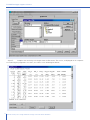
Step B4: Mark the “Auto Increment Name” option in the Auto Name Control select box. Each retrieved data file will
get a name according to the format “DataXXX.dat” in which XXX is a number which automatically increments when
a new file is down loaded.
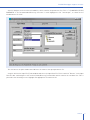
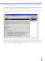
Step B5: Click the file name in the File Naming Options location (in the current example this is Data031.dat). A box
similar to Windows Explorer appears which allows the user to navigate to the location where he or she wants to store
the retrieved data files. See the window below.
Manual
23
PC208W Datalogger Support Software
File
Options
Data
Tools
Help
Sty1192/Stvi716
SM4M/SM16M
Gard
iStatusBox
l (Module Pointers
File Format
a. Comma separated
CuAiS with Array ID's
C As Stored
Next Detaille Name
Save in:
File Naming Options
Data031.tiat
Auto [..lame Control
151
_q Input
Data001.dat
I] Data007.dat
141Data01 adat
2 Data002.dat
Data002.dat
Data0Oadat
Data009.dat
Dato004.dat
Data1:110.dat
6" Auto Increment Name
r Append ti: Current File
Data005.dat
Data011.dat
2 Data014.dat
2 Data015.dat
2 Data016.dat
2 Data017.dat
DataLlIkl.dat
II Data1_112.dat
2 Data151:::.dat
ial DataOlad
PiData020.d
2 C)ata1:121.d
Pj Data1:122.d
2 Data023.d
2 Datal_124.d
New Name for Each Fill
41
rvlcidule Directory
rGet All
Get New
%Setup ifrogmsD
File name:
Save as type:
I
IData0:31.,dat
Save
Daa Files
r Open as read-only
rase/
I
If the user has opted for the Recommended Directory Structure (see paragraph 4.2), data files captured from the
SM4M should be stored in the following folder:
C:\CAMPBELL\FILES\INPUT
Step B6:
Click the “Get New” button. This option collects all “new” data files from the SM192, i.e. all files not
yet retrieved from the storage module in a previous down load operation. Each single SM4M data file is stored in an
individual DAT file on the hard drive.
For ease of reference, the above presented steps are listed in Annex 2.
5.2.4 Pointers
The Module Pointers area of the Status Box lists four different parameters, i.e. Free Space, Storage Ref. Pointer,
Display Pointer and Dump Pointer. Each of which is briefly discussed below.
Free Space: As implicated by its name, Free Space concerns the number of free data locations in the SM4M.
Storage Ref. Pointer: The Storage Reference Pointer (SRP) points to the SM4M location where the next data value
will be written.
Display Pointer: The Display Pointer points to the location which holds the first value which will be output in
response to the ‘Get One’ or ‘Get New’ data button in the Data Control Section of the software.
The pointer can be set to any desired location by using the Display Pointer position box in the Advanced section
of the data control status box, either by typing in the required location or clicking on the green arrow to move the
pointer to successive filemarks. This option is used to re-down load data from the SM4M which has already been
retrieved in a previous operation. This can be useful in case of data loss.
24
Data Retrieval, Processing and Final Storage in the Nile Basin Database
PC208W Datalogger Support Software
Dump Pointer: The Dump Pointer is an internal pointer used for keeping track of the current ‘start-of-dump’ for
module-to-module data dumps. It indicates the first location from where new data should be collected. It is a function
of the software to move this pointer after each successful data collection. Or it is the final storage location up to
which data has been downloaded to the storage module in previous dump sessions and consequently represents the
location from where data transfer will start in the default situation.
Especially the Display Pointer is useful if data is lost or corrupted during processing on PC. By manually setting
back the Display Pointer (see above and the on-line help for the appropriate instructions), data files can be
re-retrieved and re-processed, provided they still exist on the SM4M Storage Module.
5.2.5 Erasing Data on the Storage Module
The user can decide to erase the information stored on the SM192. This applies both to data files and datalogger
programs. However, since the storage module is put by default in ring mode, there is no need to erase data at any
time. The moment the module is full, it starts overwriting the eldest information in the unit with new one, in this way
never restricting ‘new’ information to be recorded.
If the user would decide that periodic cleaning of the storage module serves his or her purposes, for example to
avoid confusion between two different field visits, the below text presents instructions how to do this.
To activate the Erase Control screen, click the “Erase” tab at the bottom-left of the SMS Window. The below
presented screen will appear.
a,sms
File
Options
CSM1
Data
Tools
Help
Erase Data
StatusBox
Module Pointers
Free Space
Storage Ref Pointer
Display Pointer
DumpPointer
This option restores programs after
erasing data and programs.
Erase Data and Programs
2069180
ii
27841
27841
27841
Module Values
This option erases all data and
programs.
Erase and Test Module
SM4M/SM16M
PC Card
tyil 92/5 ty171
CF; 1
Good FLASH blocks
64
Error Cc' unt
o
2
Programs
Switch Settings
76800/9600 Baud
This option erases all data and
programs, and takes more time.
Ring Mode
Address 1
--VtatusA.Advanced
_.
Data.,E rase,/
{t
Disconnect
I
I
Update Status
I
Abort
I
The Erase Control box contains three different options, each having self-explanatory names. Since it is advised to
leave an uncorrupted version of the applicable datalogger program at all times in program location 8 of the storage
module, the recommended option is number 1: Erase Data. No further user interactions are required.
Manual
25
PC208W Datalogger Support Software
5.2.6 Trouble Shooting
Problem 1:
SM4M does not respond by clicking the “Connect” button and is giving the message “Standard
Prompt Not Detected”.
Cause: 1: Cables are not properly connected 2. Power supply 3. SC532A interface is not properly connected 4.
Problem with the COM Port or wrong SMS “Setup”
Remedy 1.1: Check if the cables are connected firmly and if they are according to the following diagram
Remedy 1.2: Check if the provided class 2 transformer is connected to a 110VAC power supply. For this purpose
use a quality 220/240 to 110/120 converter. The SC532A interface needs 12 VDC to power up therefore the class
2 transformer has an output of 12VDC which is sufficient to power the interface. Do not use any other unreliable
adaptor with an output of 12 VDC to power the interface otherwise the interface will blow and will stop working.
Remedy 1.3: Both ends of the SC532A interface have a nine pin holes. The “PC” marked end of the interface should
be connected to the nine pin computer cable while the “Peripheral” marked end of the interface should be connected
to the nine pin SC12 cable.
Remedy 1.4: The computer cable should be, in most cases using either COM Port 1 or then COM Port 2. In the
SMS “set up” check first COM1 and if it does not work then check COM2. If the problem persists then check if
the respective COM Port is not shared by any other software. In the SMS setup do not highlight/activate the “Via
Datalogger” check box.
5.3
Report Utility of the PC208W 3.3 Software
5.3.1 Introduction
The Report utility, also often referred to as Split, is used to separate individual meteorological parameters from the
raw data files and put them into a format used in the various ‘target’ databases. It essentially performs the following
operations (a) reads an input raw data file (b) extracts, splits and re-arranges data in accordance with the predefined
criteria specified in a specific parameter file for each type of data; and (c) stores the result in an output file.
5.3.2 Processing Data from Met Station
5.3.2.1General
Each Automatic Meteorological Station established within the Project is equipped with 6 electronic meteorological
sensors for measuring a set of six climatological parameters i.e. (a) solar radiation (b) air temperature (c) relative
humidity (d) wind speed (e) wind direction and (f) rainfall. These parameters are measured at an interval of 5 minutes. At the same time the datalogger periodically records two station performance indicators: battery voltage and
program signature. The METSTAT datalogger program has been designed to process all measurements and store in
its memory the following four groups of data:
•
•
•
•
26
5-minute rainfall time series with date and time of occurrence. To avoid excessive repetition of zero rainfall
values and thus waste of datalogger memory, the 5-minute intervals during which no rainfall has occurred
are omitted from the records.
Hourly time series containing values of the following meteorological parameters: average hourly air
temperature, relative humidity, wind speed, wind direction, and cumulative values of hourly solar radiation
Daily time series containing values of the following meteorological parameters: daily average, maximum and
minimum air temperature; daily average relative humidity, wind speed and direction; and cumulative values
of hourly solar radiation.
Daily time series containing two station performance indicators – battery voltage and datalogger’s programme
METSTAT signature. These are essential to monitor and maintain in good order for proper functioning of
station’s datalogger and 6 meteorological sensors.
Data Retrieval, Processing and Final Storage in the Nile Basin Database
PC208W Datalogger Support Software
Due to the logger’s memory configuration, all four groups of data time series are written to the same storage area
in the system’s RAM in the order of their occurrence (time of recording), and consequently downloaded from the
datalogger directly via short haul modems or storage module to a PC as one single, rather unorganized raw data
file. The role of the Report utility is now to extract, separate and reorganize the scattered recordings into consistent
individual data blocks that can be appended to the existing database without too much further processing.
Report utility performs this operation through use of the so-called parameter files which have to be properly defined
for each group of data – in this particular case for (a) 5-minute rainfall time series data (b) hourly meteorological data
(c) daily meteorological data and (d) the station performance data. Each group of data is extracted from the same
single raw data file by using a specific pre-defined parameter file and stored separately into an individual output file
on the PC hard drive. At the same time the output data is displayed on screen during the programme run-time for
a first visual quality check.
Table 2 presents the various files involved. 0XX stands for the data file’s serial number.
Table 2: Various files and their function used by Report in the processing of Met Station measurements.
Input File
data0XX.dat
data0XX.dat
data0XX.dat
data0XX.dat
Parameter File
metrain.par
methour.par
metday.par
metperf.par
Function
to extract (5 minutes) rainfall information from data file
to extract 1 hour summary information from data file
to extract 1 day summary information from data file
to extract station performance information from data file
Output File
metrnXX.txt
methrXX.txt
metdayXX.txt
metprfXX.txt
Each of the four file groups given in table 3 is dealt within more detail in the next four sub paragraphs.
5.3.2.2Five – Minute Rainfall Data
Only in case of a rainfall event, a cumulative 5 minutes rainfall value is stored into the logger’s RAM at the end of the
interval. In contrast, for those 5-minute intervals in which the raingauge sensor has not registered precipitation (i.e.
the rainfall values are equal to zero), the zero rainfall values are not stored to avoid loading the datalogger memory
with meaningless information. Consequently, the 5-minute rainfall data consists of a 5 minutes time series in which
a cumulative non-zero 5-minute rainfall was registered by rain gauge sensor. Consequently, the gaps in the recorded
time series indicate dry periods without rain events at the measurement site.
Procedures for the extraction of 5-minute rainfall time series data from a raw input file and storing the result in
an output file for final processing is described in the following text:
Step C1: Activate Report by clicking the Report tab on the PC208W toolbar. The below screen appears.
Manual
27
PC208W Datalogger Support Software
Matim
ita Split Version 1.7
File
Labels
E dit
Run
F'rinter
H elp
¡Input File(s)
liutput File
Input Data File-
.
Hie Irlo
Browse
ME
-liti
Start I-._.,:inion
,Jr
_
i I Auto Detect
1
T
im
11
Offsets
A
1
Stop Condition-
Fd
I
Copy
Select
.
i
1
Step C2: Choose Open from the File menu to activate a pre-defined parameter file, as indicated in the following
window.
Split Version 1.7
Edil
File
Labels
F:un
Printer
Help
N
Dut File
upen
Rave
Save As
File Info
A,Ut
Exit
1 CACAMPBELL \FILES \FARM:1E-1 \METPERF.PAR
2 1-_::...1:61APBELLNFILE5 \PARAMEI \tviETHOUR.PAR
3 CACAMPBELL FILES \ PARA.tvIE-1
E T RAIN. PAR
4 CACAMPBELL \FILEST.6.FlAt...1E-1 \METDAY.PAR
Copy
Select
.1/,
Dpen an existing Parameter file. Pron-ipts to save current file if it has changed.
28
Data Retrieval, Processing and Final Storage in the Nile Basin Database
[.1 et ef:t
Offsets
I
PC208W Datalogger Support Software
Step C3: Navigate to the location on hard drive, which contains the parameter files. This is “C:\CAMPBELL\FILES\
PARAMETR” if the Recommended Directory Structure is used. Highlight the file “metrain.par”, as shown on the
window below. Click OK.
Split Version 1.7
File
Labels
Edit
Run
F'ririter
Help
Input File(s)
Output File
Input Data File-Open
Browse
File name:
Folders:
metrain. par
c:\campbelltfilestparametr
'citart Condtion
c:\
metday. par
methour. par
met ed.par
Stop Condition
campbell
OK
Cancel
Network...
+=ii files
parametr
EI
-Copy
R elect
List files of type:
Drives:
'Parameter Files
c:
1
Clears all settings for a new Parameter file. Prompts to save current file.
The title bar on the Split window now indicates the name of the open parameter file.
Step C4: Activate the Input File(s) sub-window and select the Input Data File. To this end click “Browse” in the Input
Data File box and navigate to the location (folder/directory) on hard disk which contains the raw data files. This is
pictured in the following screen. Highlight the appropriate file and click OK.
Manual
29
PC208W Datalogger Support Software
WS. plit - METRAIN.PAR
Labels
dit
Run
Printer
Help
Input File(s)
Output File
At Data File
13
Select Input File
Browse
-
art Condition
File name:
Folders:
data031.dat
cAcampbell1filesIinput
OK
I
data031 dat
data032.dat
data033.dat
data034.dat
data035.dat
data036.dat
data037.dat
data038.dat
op Condition
c:\
116.
campbell
files
Network...
?.j input
List files of type:
Drives:
IData files (.DAT)
.3,Date(4;3)6
ICancel
c:
LJ
TA016.DAT:1
elect input data file.
Step C5: Switch to the Output File sub-window by clicking its tab at the top-mid of the current Split screen. The
below window pops up.
a Split - METRAIN.PAR
File
Edit
Flun
Labels
Printer
Help
Output File
Input FileN
Output DataBrowse
Repor
File Format
File
ICACAMPBELLWILESIOUTPUT \ME
(
Comma
ill
C None
Column Widths
.17 Screen Display
Other..
File
C Printer
Report and Column HeadingsRepOtt Heading
1olumni4
1
Element/Field# 2
Hyet.Doraph
2
3
3-
Date(4;3)
-
4
5
5
8
I
Filename
DATACI31.DAT DATA031.D.AT DAT.6.031.DAT DATA031.DAT DATA,031.DAT
Line 1
LoggerlD
Line 2
[-I
Line 3
Year
Date
Tin-le
[MMDD1
P
7
E
-
lir
Rain
[mm]
1[HHMM]
Decimal
11
i 11
Time Series Heading
30
Data Retrieval, Processing and Final Storage in the Nile Basin Database
Insert
I
Delete
I
Add
I
PC208W Datalogger Support Software
Step C6: In the File Name text box of the Selected Output File sub-screen, type in the name of the appropriate
output file. Apply the following naming format: “metrnXX.txt”
Make sure that the XX - serial number of the output file – is the same as of the respective raw data file. For
instance, give the name “metrn31.txt” to the output file if it is being extracted from “data031.dat” raw data file. Click
OK. This process is presented in the windows given below:
ni Split - METRAIN.PAR
File
Edit
Run
Labels
Printer
Help
Output File
Input File(s)
Select Output File
Output Data
\EAtyi PI
Brose
File name:
Folders:
ell\files\outputlmetrn31.txt
c: \ campbell \files \output
OK
Cancel
c:\
tj campbell
Screen Display -111
pReport and Column Head
Network...
files
output
eport H eadind
C011.11-nnff
Element/Field
Filename
DATA,03.
List files of ype:
Line
Logged
jOutput files (.PRN)j
-
Line 2
[
Drives:
Line :3
Time Series Heading
Insert
I
Delete
Add
Select/enter output data file name. Default extension is .PRN
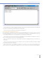
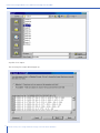
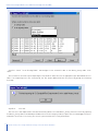
Step 7: Finalize the routine by selecting Go from the Run menu. The results, as presented on computer screen, are
similar to the window given below:
Manual
31
PC208W Datalogger Support Software
S plit R un 1.7
Hyetograph
LoggerID
Year
Date
Time
[ -]
[ -]
[ /MD]
[H-1121]
[mm]
5
9 7
2001
9 9
2001
9 9
5
2001
eading files completed.
1450
.1
5
125.5
.1
1300
.1
Lines Re
97 j
Lines Written
3
Pause
Rain
Mk.]
Close
For each five-minute interval in which rainfall has been registered at the station, the following information is
extracted from raw input data file: station datalogger-ID, year, date and time and cumulative five-minute rainfall
values. The first four values (i.e. ID, year, date and time) guarantee that each array is uniquely identified.
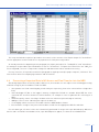
The associated output file is in comma separated ASCII format. This is shown below for the output file “metrn31.
txt” referred to in the above screen; the file can be opened and viewed by Windows Explorer or any other software
capable of reading ASCII text format. In the following case the respective Output File is opened using the View utility
of the PC208W 3.3 software.
32
Data Retrieval, Processing and Final Storage in the Nile Basin Database
PC208W Datalogger Support Software
c....Naschwyfic - View - CACampbelltFilestOutputtmettn31.txt
File
Vie.o.e Help
g
fF
All arrays
17 7
5,2001,9 7,1450,.1
5,2001,9 9,1255,.1
5,2001,9 9,1300,.1
This concludes the user activities in Report with respect to the extraction of 5-minute rainfall time series data from
the respective raw data input file downloaded from storage module.
For ease of reference, the above-presented steps are listed in Annex 3.
5.3.2.3Hourly Meteorological Time Series
As in the previous, the procedure for extraction of hourly meteorological time series data is similar to the one
described in paragraph 5.3.3. The reader is referred to the above text and Annex 3 for detailed instructions on step
1 to 5 keeping in mind that in this case the parameter file “methour.par” should be used.
Steps 6 and 7 are discussed in more detail in the remaining part of this paragraph, even though these steps are
also essentially analog to the ones discussed in paragraphs 5.3.3.
Step C1-5: Perform the same actions as presented in the previous paragraph. But now use parameter file
“methour.par”.
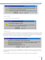
Step C6: In the File name text box of the Select Output File sub-screen, type in the name of the output file. Apply
the following naming format: methrXX.txt
Make sure that the “XX” – serial number of the output file – is the same as of the respective raw input data file. For
instance “methr31.txt” if originating from “data031.dat”. Click OK. This process is presented in the below window.
Manual
33
PC208W Datalogger Support Software
Split - METHOUR.PAR
File
Edit
!In
Labe
Printer
e
Output File
Input File(s)
Output Data
Select Output File
File
Browse
File name:
methr31.txt
CAM P
I
Folders:
OK
I
Cancel
I
Network...
I
cAcampbellfiles\output
1.7. Screen Display
c:
campbell
Report and Column Heac
?-A files
Report Heading
Column II
output
=
1
Elerrient/Fieldt# 2
Filename
C:IATAID1
Line 1
Log_ID
Line 2
[-]
List files of type:
lOutput files (r.PRN]
II
Drives:
c:
1
Line :3
Mi.
Decimal
211
Insert
Time Series Headino
Delete
Add
1
Select/enter output data file name. Default extension is .PRN
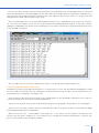
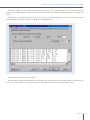
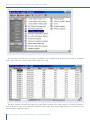
Step C7: Complete the routine by selecting Go from the Run menu. The results, as displayed on screen during the
programme run-time, are similar to window given below:
Split Run 1.7
Hourly Meteorological Data
Lo
ID
Year
[-]
[-]
5
2001
9001
2UU1
2001
2001
2001
2001
2001
2001
2001
20U1
2001
2001
2001
20U1
2001
2001
2001
9 9
9 9
9 9
9 9
9 9
9 9
9 9
9 10
9 10
9 10
9 10
9 10
9 10
9 10
2n111
Ci
5
5
5
5
5
5
5
5
5
5
5
5
5
5
s Read
!Fes Written
34
Date
[MMDD]
9
lU
9 10
9 10
9 10
197
186
In
Time Avg-nap
[HHMM]
[C]
1800
1900
2uuu
2100
2200
2300
2400
100
200
300
400
500
600
700
800
90A
1000
1100
12nn
22.76
22.07
20.93
20.34
20.32
20.84
19.94
19.59
19.34
18.9
18.37
18.1
17.78
17.85
20.68
24.04
25.9
26.23
2A_S
Avg-VP Avg-VPD Tot_Sol Aug Usp
[kPa]
[kPa] [MJ/M2]
[M/S]
2.015
1.997
2.007
2
1.842
1.704
1.756
1.807
1.888
1.823
1.645
1.573
1.622
1.664
1.732
1.772
1.682
1.671
1_7
.753
.657
.469
.387
.541
.759
.574
.472
.355
.328
.067
.36
.466
0
.504
0
.413
.379
.716
1.22
.018
.595
1.659
1.736
1_7A1
0
0
0
0
0
0
0
0
0
1.477
2.337
3.031
l_11A
1
Pause
Data Retrieval, Processing and Final Storage in the Nile Basin Database
Close
1.258
.992
.818
.538
1.587
1.132
1.186
1.366
1.164
1.367
1.235
.644
.569
.452
.578
.94
1.053
1.648
2_1.57
PC208W Datalogger Support Software
For each full hour the Met station has been operational, the following hourly meteorological data are extracted
from raw input data file: station datalogger-ID, year, date and time, average hourly air temperature, vapor pressure,
vapor pressure deficit and wind speed; and total hourly solar radiation. The first four values (i.e. ID, year, date and
time) guarantee unique identification of each array.
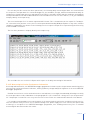
The associated output file is in comma separated ASCII format. This is shown below for the output file “metrn31.
txt” referred to in the above screen; the file can be opened and viewed by Windows Explorer or any other software
capable of reading ASCII text format. In the following case the respective Output File is opened using the View utility
of the PC208W 3.3 software.
File
Caegisdeff 5-chmitific' - View - CACampbellFilestOutputlmethattxt
Yievy Help
r-fF
71 7
IAll atas
5,2001,9 5,1500,27.54,2.253,1.429,2.782,1.388
5,2001,9 5,16cHD,25.86,2.239,1.095,1.423,1.38
5,2001,9 5,1700,25.75,2.222,1.094,.94,1.244
5,2001,9 5,1600,24.41,2.137,.921,.294,1.04
5,2001,9.5,1900,23.05,2.185,.634,. 044,.
48
5,2001,9 5,2000,21.6,2.179,.
5,2001,9.5,2100,20.94,2.232,.244,0,.508
5,2001,9 5,2200,20.64,2.196,. 23.5,0, . 673
5,21:11:11,9 5,2:31:11:1,21:1.1.5,2.089,.27,0,. 712
5,2001,9 5,2400,19.85,2.059,.258,0,.952
5,2001,9 6,100,19.36,2.006,. 24,0,1.228
5,2001,9 6,200,18.79,1.922,.247,0,. 431
5,2001,9 6,300,18.74,1.859,.302,0,.624
5,2001,9 6;400,18. 97,1.868,.324,0; 985
5,2001,9 6,500,18.92,1.887,.298,0,.657
5,2001,9 6,600,18.78,1.87,. 296,0,1.033
?nn
4 Ilk
pf. 1
77 fli:
1
ri??
This concludes the user activities in Report with respect to the hourly meteorological data series.
5.3.2.4Daily Meteorological Time Series
Compilation of daily meteorological information is a similar process as the one described in paragraph 5.3.3 and
5.3.4. The reader is referred to this text, and Annex 3, for detailed instructions on steps 1 to 5. In this particular case
the parameter file “metday.par” should be used.
Steps 6 and 7 are discussed in more detail in the remaining part of this paragraph, although all these steps are
essentially analog to the ones discussed in paragraph 5.3.3.
Step C1-5: Perform the same actions as presented in the previous paragraph. Use parameter file “metday.par”.
Step C6: In the File name text box of the Selected Output File sub-screen, type in the name of the output file. Apply
the following naming format: metdayXX.txt
Make sure that the “XX” – serial number of the output file – is the same as of the respective raw data file. For
instance, give the name “metday31.txt” to the output file if it is being extracted from “data031.dat”. Click OK. This
process is presented in the below given window:
Manual
35
PC208W Datalogger Support Software
5 Split - METDAY.PAR
File
Edit
Run
Labels
Lifts!
Printer
Help
Output File
Input File(s)
Output Data
File
Select Output File
Browse I
__1.
File name:
Folders:
metday31.txt
c:Icampbell\files\output
1.7 Screen Display
Cancel
A c:\
A campbell
.rReport and Column H
Network...
A files
Report Headir g
Columnii
OK
I
output
11
E len-lent/Field# Filename
DAT:
Line .1
Loa
Line 2
[
DA
List files of type:
Drives:
!Output files (.PRN)
c:
Line 3
[lei:41-131
21_
Insert
Time Series Heading
Delete
I
Add
Select/enter output data file name. Default extension is .PRN
Step C7:
Complete the routine by selecting Go from the Run menu. The results, as displayed on the computer
screen during the programme run-time, are similar to the window given below:
Split Run 1.7
Daily Climatological Values
Loo ID
W_spd
Year
iLdir
U_std
[-]
[-]
[ump]
Date
2001
9 5
12.97
83.5
.9
5
2001
9 6
5.737
77.6
.986
5
2001
9 7
328.1
67.14
1.139
5
2001
9 8
298.7
78.2
1.032
5
2001
9 9
303.8
73.8
.991
5
2001
9 10
24.99
84.9
1.346
5
2001
9 11
308.8
84.5
1.154
5
2001
9 12
306.4
61.26
1.032
Reading tiles completed.
5
Lines Read
Lines Written
36
avg_T
max_T
[117]
[C]
[kPa]
[kPa]
21.23
28.05
17.04
2.037
.534
1
19.01
23.09
29.59
18.32
2.119
.763
0
20.64
22.85
31.14
18.65
2.068
.773
.1
19.38
22.77
28.32
17.64
2.002
.817
0
21.89
22.24
28.18
19.72
2.065
.638
.2
14.29
22.74
28.45
17.1
1.798
1.027
0
26.17
24.11
29.26
18.85
1.932
1.123
0
26.45
21.67
29.46
17.64
1.399
.738
0
13.66
min_T
avg_VP avg_VPD
197
8
Pause
Stop
Close
Data Retrieval, Processing and Final Storage in the Nile Basin Database
Rain
SolRad
[mm] [MJ/M2]
PC208W Datalogger Support Software
For each day the Met station has been operational, the following daily meteorological data are extracted from
the respective raw input data file: station datalogger-ID, year and date, average, maximum and minimum daily air
temperature, average vapor pressure and vapor pressure deficit; total daily rainfall and solar radiation; average daily
wind speed and direction and standard deviation of the wind direction. The first three indices (i.e. ID, year and date)
uniquely identify each output array.
The associated output file is in comma separated ASCII format. This is shown below for the output file “metday31.
txt” referred to in the previous screen; the file can be opened and viewed by Windows Explorer or any other software
capable of reading ASCII text format. In the following case the respective Output File is opened using the View utility
of the PC208W 3.3 software.
The first three parameters uniquely identify each output array.
IN Campbell" Scientifk - View - CACampbelltFileslOutputtmetday31.txt
Eile yiew Help
A c_1
.1
FfF
I1/ All arrays
8
IMP
g
5,2001,9 5,21.23,28.05,17.04,2.037,.534,1,19.01,.9,12.97,83.5
5,2001,9 6,23.09,29.59,18.32,2.119,.763,0,20.64,.986,5.737,77.6
5,2001,9 7,22.85,31.14,18.65,2.068,.773,.1,19.38,1.139,328.1,67.14
5,2001,9 8,22.77,28.32,17.64,2.002,.817,0,21.89,1.032,298.7,78.2
5,2001,9 9,22.24,28.18,19.72,2.065,.638,.2,14.29,.991,303.8,73.8
5,2001,9 10,22.74,28.45,17.1,1.798,1.027,0,26.17,1.346,24.99,84.9
5,2001,9 11,24.11,29.26,18.85,1.932,1.123,0,26.45,1.154,308.8,84.5
5,2001,9 12,21.67,29.46,17.54,1.899,.738,0,13.66,1.032,306.4,61.26
This concludes the user activities in Report with respect to the daily meteorological information.
5.3.2.5Meteorological Station Performance Information
As already indicated earlier, the METSTAT datalogger programme includes routines for permanent monitoring of the
two essential station performance indicators, namely (a) battery voltage and (b) the signature of the active METSTAT
datalogger programme.
Detailed instructions to retrieve and evaluate these two indicators are straight forward and by following essentially
the same procedures as described above in the paragraphs 5.3.3, 5.3.4 and 5.3.5 – taking care to use the parameter
file “metperf.par” instead. For users easy reference these instructions are summarized in Annex 5 of the Manual.
It is strongly recommended to assess performance of the meteorological station after each data retrieval exercise.
This will facilitate timely action in case of malfunctioning of the power supply unit at the station (solar panel and/
or battery) or corruption of the METSTAT datalogger programme, thus avoiding unnecessary loss of valuable
meteorological data measured at the station.
Manual
37
PC208W Datalogger Support Software
There is no need to archive the output file containing the station performance information. After assessment of the
station performance indicators (which will lead to a decision to either take or not take an action) this information can
be printed out for records and the respective file deleted thereafter.
5.3.2.6Renaming Meteorological Output Files
Once the 5-minute rainfall, hourly and daily meteorological data time series data have been extracted and stored in
the output files, a consideration should be given to suitably rename them. This may be important in particular when a
large number of raw data files (containing measurements from more than one station, as may be the case in Uganda)
is downloaded from storage module to PC and processed at the same time; this operation will unavoidably result
in a large number of output files of the type “metrnXX.txt”, “methrXX.txt” and “metdayXX.txt” without a possibility
to really know to which particular meteorological station these output files refer to, as it is not visible from their
names.
To suitably rename the meteorological output files so as to enable the user to figure out both the type of data and
the station the data have come from, by merely reading the output file name, the following simple procedure can be
used:
•
•
•
•
•
•
immediately after processing the particular raw input file and thus creating an output file of the type “metrnXX.
txt”, “methrXX.txt” and “metdayXX.txt”, activate Windows Explorer and then open and view the respective
output file (for example, open the file “metday31.txt”).
take note of the Station Datalogger ID while viewing the file, and from this ID identify the station datalogger
the viewed data are coming from (as an example, let’s assume it was established that the extracted data in
the output file “metday31.txt” are referring to daily meteorological data observed at the Meteorological Station
Kadenge established at the Kenyan part of the Nile Basin).
Close the respective file (“metday31.txt” in our case).
Highlight the same file again in the Windows Explorer, click the right mouse button and select “Rename”
option in the menu that will show up on the screen.
Move cursor to the beginning of the file name and type in a three letter prefix which will uniquely define the
station, without changing/deleting any part of the old output file name (in our example, add say KAD prefix at
the beginning of the file “metday31.txt” so that the renamed file reads: “KAD_metday31.txt”.
Click the left mouse button anywhere in the Windows Explorer area to complete the operation and repeat the
whole above sequence for all other output files.
From a renamed output file the user can now easily identify all the necessary information as follows: (a) what is the
station the data have come from (from three-letter prefix, “KAD” in our example signifying the Kadenge Met station);
(b) what type of station is in question (from the next group of three characters, “met” in our example signifying the
meteorological station); (c) what type of data are stored in the file (from the next group of three or two characters,
“day” in our example so the file contains daily meteorological time series data); and (d) what is the name of the raw
data file the output data have been extracted from (from the last two characters containing a serial number, in our
example “31” denoting that the output file has been extracted from the raw data input file “data031.dat”).
38
Data Retrieval, Processing and Final Storage in the Nile Basin Database
Data Processing in MS Access and Final Storage into the NBD
Final Processing in MS Access and Final
Storage into the NBD
6.1
General
Final destination of the meteorological data obtained from the Automatic Weather Stations in The Nile Basin
Monitoring Network is the NBD: The Nile Basin Database developed in MS Access. But prior to reaching the final step
of adding newly observed data to this database, one more intermediate operation has to be performed: importing the
ASCII files generated by Report (as described in chapter 5 of this Manual) into MS Access and restructuring them
into a final NBD format.
Figure 5 shows the remaining part of the data trajectory, i.e. the preprocessing actions in MS Access.
Import an ASCII text file,
generated by “Report” utility in
chapter 5, into auxiliary table
“NBD_PreProcessing” in MS
Access database
Run pre-defined MS Access query
for final data processing
The results are automatically
stored into the final NBD data
table in standard format
Move raw input and preprocessed
output data files (with file
extensions “dat” & “txt”) into the
Backup sub-folder for temporary
storage
Figure 5: Final data processing steps in MS Access and subsequent removal and storage of raw files as backups.
The following paragraphs will present the detailed instructions for performing the tasks indicated in the above
figure.
6.2
MS Access Database “NBD_NEW DATA”
The remaining data processing activities are carried out in an MS Access database file called “NBD_PreProcessing.
mdb”. The users will find this file in one of the following folders (given with full path name), depending on the country
and this file structure is required to be kept unchanged at all times:
•
•
•
Users in Kenya:
Users in Rwanda:
Users in Uganda:
C:\MyDbase\NBD NEW DATA\Kenya Preprocessing
C:\MyDbase\NBD NEW DATA\Rwanda Preprocessing
C:\MyDbase\NBD NEW DATA\Uganda Preprocessing
Manual
39
Data Processing in MS Access and Final Storage into the NBD
This database file (NBD_Pre Processing.mdb) contains several pre-defined objects including 4 tables and
3 process-append queries. The database tables and queries names are listed in table 4 together with a brief
description of their function.
As indicated by their numbering, the various database objects listed in table 4 are divided into three different
groups.
•
•
•
Group 1 consists of 3 auxiliary tables in which to import the respective comma separated ASCII files generated
in Report (see chapter 5).
Group 2 consists of a single ID-converter table used to convert into a final station identification code in
accordance with either the Hydromet coding system or the one which is in force in each country of the Nile
Basin.
Group 3 consists of 3 process-append database queries specifically designed to generate records in the final
NBD database format from data in the respective auxiliary table in Group 1 and to automatically append these
records into the appropriate file and table of the NBD database.
Table 3: Database objects and their function in MS Access database file “NBD_Pre Processing.mdb”.
Type
Group
Object Name
Function
Group 1
Table
1.1
Meteo-Daily
Pre-defined table in which to import comma separated ASCII
file “metdayXX.txt” generated by Report (see paragraph 5.3)
Table
1.2
Meteo-Hourly
Ditto for “methrXX.txt”
Table
1.3
Meteo-5minRain
Ditto for “metrnXX.txt”
Table
Group 2
ID Converter
Table relating datalogger IDs to Hydromet station number or
other identifier
Group 3
Query
3.1
Meteo_Daily AWS
A pre-defined query used to process data from the respective auxiliary table “Meteo_Daily” in order to generate records
in the NBD format, and to automatically append/store such
records in the NBD table “AWS Meteo _Daily Data”
Query
3.2
Meteo_Hourly AWS
Ditto for auxiliary table “Meteo-Hourly” and final NBD table
“AWS Meteo _Hourly Data”
Query
3.3
Meteo_5minRain AWS
Ditto for auxiliary table “Meteo-5minRain” and final NBD table
“AWS Meteo _5minRain Data”
The final NBD tables in which the processed data will ultimately be stored/appended are located in the following
database files (including the whole folder/directory path):
NBD tables (a) “AWS Meteo _Daily Data” (b) “AWS Meteo _Hourly Data” and (c) “AWS Meteo _5minRain Data” are
located in:
•
•
•
C:\MyDbase\NBD\Daily Hydro-Meteorological Data\Daily Clim Kenya.mdb – for data observed at the
meteorological stations in Kenya (for the time being there is only one such station established by the Project)
C:\MyDbase\NBD\Daily Hydro-Meteorological Data\Daily Clim Rwanda.mdb – for data observed at the
meteorological stations in Rwanda (there is only one such station).
C:\MyDbase\NBD\Daily Hydro-Meteorological Data\Daily Clim Uganda.mdb – for data observed at the
meteorological stations in Uganda (there are three such stations established by the previous project and 2
more by the present project in Uganda).
The above paths (folder/directory structure) are included into the respective pre-designed MS Access queries
indicated in table 4 and should not be changed by the user as any change of the folder/directory structure will result
in loss of the processed data.
The individual database items in a particular object group are subject to similar final processing. For example,
40
Data Retrieval, Processing and Final Storage in the Nile Basin Database
Data Processing in MS Access and Final Storage into the NBD
the actions for importing ASCII text file “metdayXX.txt” into MS Access are equivalent to those for “methrXX.txt” and
“metrnXX.txt”, only table and file names differ. The same applies for running the various queries and adding the fully
processed data to the NBD.
It is because of this fact, and the wish to avoid redundancy, that this manual presents the detailed user instructions
for only one member of each data type. The instructions for the remaining members are analog.
Last but not least, if the user decides to suitably rename the output ASCII text files – as described in chapter 5 then
the original names of all the respective ASCII output text files given in table 4 above will be different; in this case,
each file name will have a three-letter prefix and underscore added to indicate the station name. To illustrate this by
using the same examples as in chapter 5, the name of the file “metday31.txt” would change into “KAD_metday31.
txt” and so on.
6.3
Importing Output ASCII Text Files Generated by Report into MS Access
This paragraph describes procedures for importing output ASCII text file “methrXX.txt” into MS Access file “NBD_Pre
Processing.mdb”. The same or similar commands are applied for importing “metdayXX.txt” and “metrnXX.txt”.
Step D1: Open the MS Access file “NBD_Pre Processing.mdb”; consult paragraph 6.2 above to locate the appropriate
folder/directory path of the file, which is country-dependent. In table view, the following database window appear
,
LVBD_Pre Processing : Database
14 Design
Objects
on
f-
Create table in Design view
Create table by using wizard
Create table by entering data
ID Converter
fleteo_5minRain
ryleteo_Daily
Meteo_Hourly
Groups
The above view shows the 4 pre-defined tables as specified in table 4.
Step D2: Highlight the auxiliary table “Meteo_Hourly” and click “Open”. This results is illustrated in the following
screen:
Manual
41
Data Processing in MS Access and Final Storage into the NBD
Meteo_Hourly : Table
Datalogger-ID
Time
Year
200195
1500
1800
/11 Avg-VP
20.84
20.15
19.86
2.253
2.239
2.222
2.137
2.185
2.179
2.232
2.196
2.089
2.059
1 -J..36
.L.1_11 _1b
27.541
-
21101 9 !r-1
1700
25.86
25.76
2001 9 5
?OW 9 5
1800
24.41
1900
T.,001 9 F,
2000
23.05
21.6
5
2001 9 F.,
5
5
2001 9
?OW 9
2100
2200
5!
T)001 9 F,
?001 9
5
L W]
Record: H
Avg-T
20 .i.J 4
23001
2400
h
I i*I of 186
4
In the above screen, the Meteo_Hourly table still contains data from a previous transfer exercise. Although primary
key setting in the final NBD tables do not allow for data duplication, it is good policy to delete all records from the
auxiliary tables, in this case Meteo_Hourly, prior to a processing new data set. To this end, continue with step 3.
Step D3: Select all records by simultaneously keying CTRL and A, or clicking Select All Records in the Edit menu.
The complete record set is now highlighted.
Step D4: Delete all records by choosing Delete Records from the Edit menu, or by pressing the ‘Delete’ key as
shown on the following screen:
Microsoft Access
.1
Insert Format
File 1 Edit
Dj4K1cantUr1dp
g cut
Records
'
Ctrl+Zr.
Ctrl+X
ink Copy
Tools Window Help
7:61
bc)
-
75y7L-L
Ctr1+11
MM-DD
Delete
Del
19( Delete Record
Der-'Select Record
Select All Records
Ctrl+A
Find...
Ctrl+F
Go To
Time
42
11
*xloia.
195
95
95
95
95
95
95
95
Avg -T
1500
1600
1700
1800
1900
2000
2100
2200
2300
2400
100
Record:
Yo Y=1
Ctrl+C
e Paste
it4
N
'
II
1 I+l of 186
Data Retrieval, Processing and Final Storage in the Nile Basin Database
27.54
25.86
25.76
24.41
23.05
21.6
20.94
20.64
20.15
19.86
1
,_b7-777-14
Avg -VP
2.253
2.239
2.222
2.137
2.185
2.179
2.232
2.196
2.089
2.059
2.006
Data Processing in MS Access and Final Storage into the NBD
Step D5: Close Meteo_Hourly table.
The auxiliary Meteo_Hourly table is now empty. No data duplication will occur during data import process unless
the user imports a certain data set twice. Although this would eventually be refused by MS Access due to ‘key
violation’, it is recommended not to enter this situation. Continue with step D6.
Step D6: In the database window, select Get External Data from the File menu. Choose the sub command Import,
as presented below.
Microsoft Access
Edit
Vie..
Insert Tools V.iridow Help
Ctrl+N
Ctr1+0
Import...
Get External Data
+El Link Tables...
Close
Save
Save As...
Export._
Page Seti_jp...
aPrint Preview
Print...
Ctrl+P
Send To
Database Properties
1 C: MyDbase '1,nbd'IJABD P.JEV.1 DATA
F
\ganud.'re.
F TocessinaVED_F're ProcesSIng
2 C: \rylyDbase \ntid 1, Daily Hydro-Meteorological Data \D.A.:" Clim Uganda
3 CAMyDbase
1, Daily Hydro-Meteorological Data \Daily Clim Rwanda
4 CAMyDbase \nbd \Daily Hydro-Meteorological DataWb1
,1111111
Exit
Step D7: In the subsequent window, navigate to the folder containing the Report output files and select the concerned “methrXX.txt” file. Use the appropriate Windows Explorer operations. If the recommended directory structure
is used, “methrXX.txt” is stored in folder C:\CAMPBELL\FILES\OUTPUT. Make sure the ‘Files of type:’ box below-left
is set to Text Files. The resulting screen is depicted below:
Manual
43
Data Processing in MS Access and Final Storage into the NBD
Import
Look in:
:j
ji C_Aitput
- Toots
metday2
metday31
Methr16
rnetprf 1
Metorf 13
,
metprf 14
Metorf 16
,
Metorf20
Metprf28
metrn2
metrn31
g] cf fOOrnh
File name:
Files of
Ipport
zJJ
Text Files
Step D8: Click Import.
The following Text Import Wizard pops up.
BEI Import Text Wizard
'Your data seems to be in a 'Delimited format. If it isn't, choose the format that more correctly
describes your data.
C; Delimited - Characters such as comma or tab separate each field
Fixed Width - Fields are aligned in columns with spaces between each field
3ample data from file: C:1,1::AMPBELL'1,FILES\OUTPLIT\METHR31.TXT.
1
2
5,2001,9 5, 1500,27.54,2.253, 1.42c1,2.7F:L., 1.388
5,2001,9 5,1600,25.86,2.239,1.095,1.423,1.38
5,2001,9 5,1700,25.76,2.222,1.094, .94,1-244
5,21:11:11,9 5,1800,24.41,2.137, .921, .294,1.04
.5
,2001,9 5,1900,23.05,2.185, .634, .044, .47
.5,2001,9 5,2000,21.6,2.179, .4,0, .48
Ady.anced...
44
111117ncel
bat
Ne:x:t >
Data Retrieval, Processing and Final Storage in the Nile Basin Database
I
Einish
Cancel
Data Processing in MS Access and Final Storage into the NBD
The Report output files are comma-separated and thus fall into the category ‘delimited’. This has been done on
purpose since importing this format into MS Access has proved to be straight forward and flawless. Continue with
step 9.
Step D9: Select ‘Delimited” and click ‘Next’. The screen illustrated below appears; it shows how the imported text
will be divided into various columns according to the applied delimiter.
INA
El Import Text Wizard
Vy'hat delimiter separates your fields? Select the appropriate delimiter ard see hco.....iyour text
is affected in the
Choose the delimiter that separates your fields:
Semicolon
Tab
C Space
Comrna
I First Row Contains Field Names
r
Other:
Text Qualifier:
1-;..rionei:-
5 2001 .; 5 1500 27 . 54 3.35:3 1.429 2.762 1.366
5 2001
5 1600 2.5 . E; 6 2.29 1 . 09.5 1 . 423 1 . 3F;
=4
S 2001
5 1700 25.76 2.222 1.094 .94
5 ? 001 95 1;E; 00 2 4 . 41 2 . 1:37 .921
. 294
. 044
1.244
1.04
.47
ii
. 4E;
:".1
5 2001 ; 5 1900 2:3 . 0 S 2.165 .634
c",
41
?cum
5
=.1
21-11-11-1
21.6
2.179 .4
I
Adlanced...
I
Cancel
< Back
Next >
Finish
Step D10: Select ‘comma’ and click ‘Next’.
The subsequent window (shown below) is used to define the output location for the imported data. In this particular
case, the new information is to be imported into an existing pre-defined auxiliary table Meteo_Hourly.
Manual
45
Data Processing in MS Access and Final Storage into the NBD
Import Text Wizard
You can store your data in a new table or in an existing table,
lyVhere would you like to store your data?
C In a Nev.) Table
6. In an Existing Table:
ID Converter
Meteo_5rninRain
5 2001 ; 5 1500 27.54 2.253 1.429 2.782 1.388
5 2001 35 1600 25.86 2.239 1.095 1.423 1.38
5 2001 35 1700 25.76 2.222 1.094 .94
1.244
5 2001 351600
160n 24.41 2.137 .921 .294 1.04
5 2 n01
=.1
5 1q0n 23.n5 7. 1E;5 .534
5 2001 35 2000 21.6
Ad±anced...
2.179 .4
CanCel
.044
D
BackI
.47
.48
Next
Step D11: Check “In an Existing Table:” and navigate in the related list box to the Meteo_Hourly table. Click
‘Next’.
This constitutes the final step in importing the ‘methrXX.txt’ ASCII file into the appropriate pre-defined MS Access
table. If no importing errors are encountered, the Text Import Wizard finishes the process by giving the following
message.
Step D12:
Click OK.
The text file is now imported into the desired auxiliary MS Access table Meteo_Hourly. View the results by opening
the Meteo_Hourly table in the database window. Check on the integrity of data, in particular, the datalogger ID values
and make corrections if necessary. The result is presented on the screen given below:
46
Data Retrieval, Processing and Final Storage in the Nile Basin Database
Data Processing in MS Access and Final Storage into the NBD
E Meteo_Hourly : Table
Datalogger-ID
Year
5
5
MM-DD
Time
Avg-T
-7)001 9 8
801D
?I:101 9 8
91DCI
T.'001 9 8
1000
2001 9 8
2001 9
.11 w
1
19.13
21.83
17)00
23.47
24.85
?5.5?
200198
!=,
2001 9 8
1400
26.91
5
2001
!=.i 8
.151:10
'7)001 9 8
buu
7)001 9 8
.171_11_1
2001 9 8
16uu
T.'001 9E:
1900
'7)001 9 Ft
.7.11:11:11:1
27.5
27.8
27.55
26.42,
24.63
24.08
!E,
Record:
14 I _4_1
1r
IF
11*1 of 186
This step concludes description of procedures for transfer of the contents of the Report Output file “methrXX.txt”
into the appropriate location in MS Access in preparation for final processing of data.
As already stated at the beginning of this paragraph, the import procedures for “metdayXX.txt” and “metrnXX.txt”
are analog to the procedures presented above for the file “methrXX.txt”. To import these ASCII files into “NBD_Pre
Processing.mdb”, the user is requested to change file and table names where and when necessary.
For easy reference, all steps discussed in this paragraph are again presented, in proper sequence, in Annex 4. This
time however without accompanying comments and illustrations.
6.4
Processing of Imported Data in MS Access and Final Transfer into the NBD
After being imported into an auxiliary table in MS Access, the new data sets are subject to the following processing
and final storage of processed data records into NBD:
•
•
•
•
•
•
two separate text fields containing day, month and year respectively, have to be converted into a single date
field;
short datalogger ID (due to the logger’s memory configuration limited to a number below 255) has to be
converted into an official numerical station identifier, for example in case of Hydromet-IDs consisting of 8
digits;
automatic quality control: checking if the data values are within an expected range of variation;
adding of ‘source’ value: indicating the origin of the data set;
re-arranging column structure in accordance with the NBD database format.
final automatic storage of the processed new data records into the appropriate NBD file and table.
For each data type, all these actions are automatically performed in one go with a pre-defined query. When the
Queries tab is activated in the database view, 3 pre-defined queries appear, as shown in the window below:
Manual
47
Data Processing in MS Access and Final Storage into the NBD
-
ITN NBD_Pre Processing : Database
[1:112pien Vtg, Design
Objects
Nev..' X
-
X
*-15-
4-4-
Create query in C:iesign
Create query by usinq
rg &IMP'
13
For
Meteo_5minRain AW5
AWS
Meteo_Hourly
Reports
Pages
Macros
Modules
Table 4 presents the input and output tables for each of the above queries. AWS stands for Automatic Weather
Station, which have been established in the region within the GCP/RAF/304/JPN and GCP/INT/752/ITA Projects.
For reference purposes, the general query design is presented in Annex 5. The function and design of the
ID-Converter table, included in the various queries, is discussed in Annex 6.
Table 4: Designated Input and Destination tables for each pre-defined append query.
Input Auxiliary MS Access
Table
Meteo_5minRain
Meteo_Hourly
Meteo_Daily
Query for Data Processing and
Final Transfer into NBD
Meteo_5minRain AWS
Meteo_Hourly AWS
Meteo_Daily AWS
Final NBD Destination Table
AWS Meteo_5min Rain Data
AWS Meteo_Hourly Data
AWS Meteo_Daily Data
Continue the data processing exercise by performing step 13.
Step D13: Finalize data processing by activating the appropriate query. For example, highlight the “Meteo_Hourly
AWS” append query to process the newly imported data set from the “Meteo_Hourly” auxiliary MS Access table to the
final “AWS Meteo_Hourly Data”. Click Open. By this operation data records in “Meteo_Hourly” table will be processed
as appropriate and final results will be automatically stored/appended into the final NBD destination table “AWS
Meteo_Hourly Data” table.
The following message box pops up.
48
Data Retrieval, Processing and Final Storage in the Nile Basin Database
Data Processing in MS Access and Final Storage into the NBD
Step D14: Click Yes.
A message box similar to the one below follows.
Step D15: Click Yes.
This steps finalizes the data processing in MS Access. The destination NBD table is by its primary key settings
protected against duplicate records. If a certain record would be added for the second time, the following message
box shows up. It indicates that the processing operation is carried out but that any double rows will not be added due
to ‘key violations’. Click Yes to perform the query to process the genuinely new data.
Microsoft Access
E3
Microsoft Access can't append all the records in the append query.
field(s) to rquii due to a tpe conersion failure, and it didn't add 121 record(s) to the table
due to key .ic'latic'ris U record(s) due to lock violations, and 0 record(s) dije to ...ealidation rule violations.
.:.?ou want to run the action query anykNay?
To ignore the error(s) and run the query click Yes.
For an explanation of the causes of the violations, click Help.
rliCrOSOft
%Les
:I
uo
Help
In order to visualize the final results stored/appended in the NBD destination table “AWS Meteo_Hourly Data”,
locate this table in the appropriate NBD folder and file (consult chapter 6.2 for this purpose) and open the table in
the database view.
Step D16: Highlight the “AWS Meteo_Hourly Data” table from the NBD file “Daily Clim Uganda.mdb”.
Manual
49
Data Processing in MS Access and Final Storage into the NBD
Oil Daily Clim Uganda : Database
12pen W.7., Design ."'m Nleke..1
qi
Create table in C:lesign view
ri
Rainf all Uganda
r:A-
Create table by using t.....lizard
El
Relati.....e Humidity ._.ganua
EI
Source
Sunshine Uganda
qjCree table by entering data
Ffl
AWS Meteo jrnin P.airl Data
E1
III
AWS Meteo_Daily Data
IIJ'yVind Run Uganda
El AWS Meteo_Hourly Data
De.'.' Point Temperature ._.ganda
El
Dry Bulb TernperaWre ._.ganda
El
._.ganda
EvaporationI
El
El
El
El
Maximum Temperature Uganda
Meteo Station Nlaster File
Minimum TernperaWre ._.ganda
Radiation Uganda
I
The following screen presents the fully processed data set in the NBD format. Note the new Station-ID, combined
Dates, Time and Source fields uniquely identifying each record.
E AWS Meteo_Hourly Data : Table
[18-sep-01
800
104
19.1
O8-5ep-1_11
1304-
104
91-17-F,!=1n
LIU-Sep-U.1
1400
104
90 3F,9 o
uu-!:ep-01
uu-sep-01
1500
104
:=F,9 n
-1600
104
91:13r,9 o
[18-Sep-01
1700
104
uu-:ep-01
18001
104
uu-! ep-01
uu-sep-01
1900
2000
104
21.8
23.5
24.9
25.5
26.4
26.9
27.5
27.8
27.6
26.4
24.6
104
24.1
903r,9 0 1
[18-Sep-01
900L
104
91-17-1,1=1n
uu-S e p-01
10001
104
91:1369 rsi
uu- e.p-01
1100
104
91-1:7F,91-11
uu-sep-Of
1200
104
!--31-17-1,!=ln
9035901
Record7larI I
[18-5e p-01
--
63.84
63.20
61 .29
60.16
57.86
53.411
ra .08
60.8A
8F1
['9 .74
74
104
2100i
.1 11.401 of 121
80.60
70.76
66.86
4
The above stepD16 concludes description of the procedures for data processing in MS Access and final storage of
processed data records into the appropriate NBD destination table. Other meteorological data files can be processed
by following the same procedures.
50
Data Retrieval, Processing and Final Storage in the Nile Basin Database
Data Processing in MS Access and Final Storage into the NBD
6.5
Transfer of Raw Input and Report Output Data Files to Backup Folder
Once the meteorological data series are successfully processed in MS Access, the raw data files of the type “dataXXX.
dat” and the respective extracted output ASCII text files, processed by using the Report utility (see chapter 5.3 of the
manual), have for all purposes become obsolete. The processed files with file extensions “dat” and “txt” are no more
needed to be stored in the sub-folders C:\Campbell\Files\Input and C:\Campbell\Files\Output, respectively, as the
user can only confuse the processed files with new files which are yet to be processed in MS Access.
For this reason, all the processed files should be removed from the above folders immediately upon completion of
their final processing in MS Access. For security reasons, however, these files are recommended not to be deleted
but rather temporarily stored in the sub folder C:\Campbell\Files\Backup; once the user is sure that these files
are no longer needed, they may eventually be deleted from hard disk or stored on other computer media if felt of
interest.
Manual
51
Exchange of NBD Data with other users
Exchange of NBD Data with other users
7.1
Problem Description
The user may occasionally be in need to transfer some data from the main NBD database to other departments or
agencies for their further use. To do so, one may require creating a smaller “Transfer” file with such data, which
can either fit on a floppy disk or can be distributed by e-mail. For instance, this type of data transfer is foreseen to
take place, on regular basis, between the regional offices in Bukoba and Mwanza; the Regional Office in Mwanza and
Directorate of Water Resources in Dar-es-Salaam; the PWO in Kisumu and Water Development Department of the
Ministry of Water Resources in Nairobi; as well as among the countries of the Nile Basin Region. A need for similar
data transfers between the FPIs and other agencies may also occasionally arise.
The text below describes step-by-step procedures for preparation of these so-called transfer files as and when
necessary for data exchange.
7.2
Preparation of Transfer Files
Step E1: By running the appropriate append query in MS Access new meteorological data records will be processed
and automatically added into the respective tables in the NBD (see chapter 6.4). Once this has been completed, open
in the NBD folder the database file and the table which contains the data records targeted for transfer/exchange,
and write down the NBD Station ID, the begin and end date of data records planned for transfer to other users. Use
a small table as shown below to write this information on a piece of paper:
NBD Station ID
…………
Begin date of data record for transfer
……………….
End date of data record for transfer
………………
Close the database table and file.
Step E2: Open a new database by checking the box “Blank Access database” by running the MS Access Programme. A new small window will appear on the screen, called “File New Database”. A default database file name
“db1.mdb” is displayed in the “File Name” field of the window and a list of folders and/or files in the main window
area. Proceed and select a folder in which the database file is preferred to be created; once the folder is selected,
continue and change the default file name “db1.mdb” into a preferred file name which would subsequently be used
for transferring selected data records to another user (either by e-mail or on a floppy disk). Also note that the extension “mdb” is a default extension for database files created in MS Access and should not be changed. Once the name
of the new database file is typed in the file name field, complete the operation by clicking “Create” button and then
by closing the new database file window; note that the created file is still empty. Remember, or better, write down
the name of newly created database file and its location by using the Windows/DOS convention for path description.
As an example, let’s assume a user has opted to create the new MS Access database file named “Transfer.mdb” in
the folder “MyDbase”; the path of the file in this case should read:
C:\MyDbase\Transfer.mdb.
Step E3: Open the appropriate main database file (for example the file “Daily Clim Uganda.mdb”) in the NBD folder
where the historical and new data have already been processed and stored. From displayed list of available database
tables in the selected file, select the appropriate target table (say the table “AWS Meteo_Daily Data” as an example);
check once again if the data records that are planned to be transferred to other users (as per the station ID, begin
and end date of data records written down in Step E1) are indeed properly stored in the selected table. Once this has
been verified, close the table (but don’t close the database file), and proceed with Step E4.
Step E4: Click on the Queries Tab in MS Access and then press “NEW” as shown on the screen below:
52
Data Retrieval, Processing and Final Storage in the Nile Basin Database
Exchange of NBD Data with other users
au Transfer : Database
410sen
esign
P.Iew
D
Create query in Design view
Objects
1;_li
Create query by IJSing
5
Form
Repor
Page
Macros
Modules
Groups
A small window called “New Query”, will pop up on the screen with the default option “Design View” automatically
highlighted. As this is exactly the option we need, proceed and click on “OK”.
A second small window, called “Show Table”, will appear on the screen. Proceed and select the database table
which contains the target data for exchange (say the “AWS Meteo_Daily Data” as an example given in Step E3) by
highlighting the table name from the list displayed in the “Show Table” window; click on “Add” and then click “Close”
button to close the show table window. The computer screen looks now as shown below:
Queryl
12g1
Select Query
Station-ID
Date
Source
r...lin-T
Avg-RH
Field:
Table:
Sort:
Show:
Criteria:
or:
E
Manual
53
Exchange of NBD Data with other users
The view shown above is called “Query 1: Select Query”. It is in this view where the user has to select/design a
query which will look into the specified database table and select the data records targeted for transfer/exchange.
Step E5: Proceed and double click on each of the field names displayed in the small window (with the name of the
queried table displayed on its top) located in the upper left corner of the above view; in our illustrative example the
name of the queried table is “AWS Meteo_Daily Data” (shown on the top of the small window) and the field names to
double click are “Station-ID”, “Date”, “Source”, “Avg_T” and so on.
The result of this operation is illustrated on the screen shown below:
Queryl
-11-j
Select Query
Station-ID
Date
source
4
ri
11=1=14.1111
Field:
Table:
corr.:
Show:
Station-ID
AWS Meteo Daily D
Date
AWS Mete°
Source
C:1
Awsryleteo DaiI
L.1
D
Avo-T
Meteo Daily LI
Max-T
L.1
Criteria:
or:
The next to do is to use “Criteria” field (located in the lower part of the above view) to specify the NBD Station IDs
and the time period (i.e. the begin and end dates) written down under the Step E1.
Step E6: First specify the station IDs by clicking in the “Criteria” cell under “Station-ID” and type the selected station ID. Then proceed and specify the begin and the end dates of the time period of interest by clicking the “Criteria”
cell under “Date” and by typing the following or similar text “between#01-Jul-98#and#30-Jul-98#” in the cell;
depending on the specific time period for which the data records are to be extracted from the main database table.
The result of Step E6 is illustrated below:
54
Data Retrieval, Processing and Final Storage in the Nile Basin Database
Exchange of NBD Data with other users
Queryl
Select Query
IPTITr-
061
Station-ID
Date
'Source
AmT
f...lin-T
H$MKEIMMINSMINMEIMMEIMMINSMKIMMEINEMOMKORMKKIMMEIMMINSMIR
Field:
:ation-ID
Nleteci Daike D
r,ort:
Show:
Criteria:
or:
9 :132901
Date
Avc-T
Source
Mebao Daily Data
e en #
401.15
D
rylebao
1 -3 uI-9 8#and#30-3 jI-98#
Step E7: Select “Datasheet View” under “View” of the MS Access main menu to see if the query is selecting properly the desired data records; if it is not, change/amend the query criteria accordingly.
Once it has been verified that the query is selecting the desired data from the appropriate main database table in
correct manner, proceed and copy the selected data records into a new table as follows:
Step E8: Go to the Query Design view and select “Make-Table Query”“ from Query” of the MS Access main menu.
Type any preferred name for new table in the blank space behind “Table Name” (say “Meteo Daily for Transfer”).
Select the option “Another Database” and type below the path and name of your new blank database file; type here
the Windows/DOS convention path which was written down under Step E2, i.e. C:\MyDbase\Transfer.mdb
Finally click on “OK”
Step E9: While still in the Query Design View, select “Run” from the “Query” main menu bar and click “Yes” to
confirm that you want to copy the specified number of records into the table located in the new database file (in our
example: table “Meteo Daily for Transfer” located in the new database file “Transfer.mdb” in folder “MyDbase”).
The extracted data are now located in “Transfer” file on hard disk and is ready for dissemination; to complete the
procedure, proceed with the next final two steps.
Step E10: In case the user opts to use a diskette for disseminating/transferring data, he/she should proceed and
copy the file “Transfer.mdb” from hard disk to the diskette using Windows Explorer utility for the purpose.
The diskette with the extracted data records is now ready for dissemination to other users.
Step E11: In case the extracted data are planned to be disseminated by e-mail, it is recommended to make the
“Transfer” file as small as possible. For this purpose the user is directed to compress the file by using either the
PKZIP or WINZIP utility before the file is e-mailed to other users as a file attachment.
Step E11 completes description of procedures for creating an Access “Transfer” database file and storage of the
Manual
55
Exchange of NBD Data with other users
selected data from any main database file/table into the newly created file as described in the steps E10 and E11.
Data stored in the “Transfer” file can now easily be transferred to other users either by e-mail or on a floppy disk.
If there is a need to transfer data from more than one station, and for different data records, the user should just
repeat the steps described above but for other stations and/or different data records. In this case each station will
have its data in a separate table but in the same Access “Transfer” file.
56
Data Retrieval, Processing and Final Storage in the Nile Basin Database
Annexes
Annexes
Annex 1:
Annex 2:
Annex 3:
Annex 4:
Annex 5:
Annex 6:
Consecutive Steps in Connecting Storage Module SM4M/SM192 to PC.
Consecutive Steps in Retrieving Raw Data Files form SM4M/SM192 Storage Module to PC.
Consecutive Steps in Processing Raw Data Files in Report.
Consecutive Steps in Final Processing of Report Output Files in MS Access and Appending
Processed New Data Sets to NBD.
General Design of the Append Queries for Pre-Processing of the Report Output Files in MS Access.
Design of the ID Converter Table.
Manual
57
Annexes
Annex 1: Consecutive Steps in Connecting Storage Module SM4M/SM192 to PC.
Annex 1: Consecutive Steps in Connecting Storage Module SM4M/SM192 to PC.
Step
A1
A2
A3
A4
A5
A6
A7
A8
A9
Action
Connect the SM4M Storage Module to the SC532A Interface using the blue SC12 cable.
Make sure the SC532A Interface is powered.
On PC, double click the PC208W Datalogger Support Software Icon.
Click the StgModule tab.
Click the SM4M/SM16M tab at the top-right corner of the SMS window.
Click the tab labeled ‘Setup’ to select the appropriate communication settings.
Select the COM Port settings corresponding to the serial port used by the “9 to 9” pin computer cable connecting
the SC532A Interface (see paragraph 3.1). In most cases this will be either COM1 or COM2.
Set Baud Rate at 19200. This is a measure of the communication speed between PC and Storage Module. In case
frequent communication problems are experienced, lower the Baud Rate and see if this solves the problem.
Click the “Connect” button to connect SM4M to PC.
The above steps are discussed in detail in paragraph 5.2.2 of this manual.
Annex 2: Consecutive Steps in Retrieving Raw Data Files from SM4M or SM192 Storage
Module to PC
Annex 2: Consecutive Steps in Retrieving Raw Data Files from SM4M or SM192 Storage Module to PC
Step
B1
B2
B3
B4
B5
B6
Action
Connect SM4M/SM192 to PC and establish communication. See instructions in paragraph 5.2.2 or Annex 1.
Click the “Data” tab at the bottom-left.
Mark the “Comma separated” option in the File Format select box. Import of comma separated ASCII files into
MS Access has proven to be flawless and error free.
Mark the “Auto Increment Name” option in the Auto Name Control select box. Each retrieved data file will get a
name according to the format “DATAXXX.DAT” in which XXX is a number which automatically increments when a
new file is down loaded.
Click the file name in the File Naming Options location. A box similar to Windows Explorer appears which allows
the user to navigate to the location where he or she wants to store the retrieved data files.
Click the “Get New” button. This option collects all “new” data files from the SM4M or SM192, i.e. all files not
yet retrieved in a previous down load operation. Each single SM192 data file is stored in an individual DAT file on
the hard drive.
The above steps are discussed in detail in paragraph 5.2.3 of this manual.
58
Data Retrieval, Processing and Final Storage in the Nile Basin Database
Annexes
Annex 3: Consecutive Steps in Processing Raw Data Files in Report.
Annex 3:Consecutive Steps in Processing Raw Data Files in Report.
Step
C1
C2
C3
C4
C5
C6
C7
Action
Activate Report by clicking the Report tab on the PC208W toolbar.
Choose Open from the File menu to activate a pre-defined parameter file.
Navigate to the location on hard drive, which contains the parameter files. This is “C:\CAMPBELL\FILES\PARAMETR” if the Recommended Directory Structure is used. Highlight the concerned parameter file and click OK.
Activate the Input File(s) sub-window and select the Input Data File. To this end click “Browse” in the Input Data
File box and navigate to the location on hard disk which contains the data files. Highlight the appropriate file
and click OK.
Switch to the Output File sub-window by clicking its tab at the top-mid of the current Split screen.
Select location for, and give a name to, the resulting Output file. To this end click “Browse” in the Output Data
box. Navigate to the desired folder on the hard drive and type in an output file name according to the convention
discussed in paragraph 5.3.2.2. Click OK.
Finalize the routine by selecting Go from the Run menu.
The above steps are discussed in detail in the paragraphs 5.3.2 of this manual.
Annex 4: Consecutive Steps in Final Processing of Report Output Files in MS Access
and Appending Fully Processed New Data Sets to NBD.
Annex 4: Consecutive Steps in Final Processing of Report Output Files in MS Access and Appending Fully Processed New Data Sets to NBD.
Step
D1
D2
D3
D4
D5
D6
D7
D8
D9
D10
D11
D12
D13
D14
D15
D16
Action
Open the MS Access file “NBD_PreProcessing.mdb” in folder
C:\MyDbase\NBD NEW DATA\Kenya Preprocessing – for Kenya, or
C:\MyDbase\NBD NEW DATA\Rwanda Preprocessing – for Rwanda, or
C:\MyDbase\NBD NEW DATA\Uganda Preprocessing - for Uganda.
Highlight the appropriate auxiliary table and click “Open”. See Table 4 in paragraph 6.2 for an overview of the
auxiliary tables (Group 1).
Select all records by simultaneously keying CTRL and A, or clicking Select All Records in the Edit menu.
Delete all records by choosing Delete Records from the Edit menu, or by pressing the ‘Delete’ key.
Close auxiliary table.
In the database window, select Get External Data from the File menu. Choose the sub command Import.
In the subsequent window, navigate to the folder containing the Report output files and select the concerned
one. Use the appropriate Windows Explorer commands. If the recommended directory structure is used, these
files are stored in folder C:\CAMPBELL\FILES\OUTPUT. Make sure the ‘Files of type:’ box below-left is in “Text
Files”.
Click Import.
Select “Delimited” and click “Next”.
Select “comma” and click “Next”.
Check “In an Existing Table:” and navigate in the related list box to the appropriate auxiliary table. Click “Next”.
Click OK.
Finalize data processing and storage into the NBD by activating the appropriate pre-defined append query. See
Table 5 in paragraph 6.4 for the required combination of query, input and output file.
Click Yes.
Click Yes.
New set of data have been stored/appended in the NBD; open the respective NBD table to check the final
results.
The above steps are discussed in detail in the paragraphs 5.3.2 of this manual.
Manual
59
Annexes
Annex 5: General Design of the Append Queries for Final Processing of the Report
Output Files in MS Access.
The function of the pre-defined append queries is to perform the final processing steps in MS Access. This
includes:
• two separate text fields containing day and month, and year respectively, are converted into a single date
field;
• short datalogger ID (due to the logger’s memory configuration limited to a number below 255) is transferred
into an official numerical station identifier, in case of Hydromet-IDs consisting of 8 digits;
• automatic quality control: checking if the data values are within an expected range;
• adding of ‘source’ value: indicating the origin of the data set;
• re-arranging column structure to NBD format.
The window below presents the design of the “Meteo_Daily AWS” append query, which uses “Meteo_Daily” as
auxiliary source table and “AWS Meteo_Daily Data” as the final destination table in the NBD.
Meteo_Daily AWS : Append Query
:+:
Datalogger-ID
Datalogger-ID
Station-ID
Station ame
AmT
Location
Latitude
Longitude
r...lin-T
Field:
Table:
Sort:
Append To:
Criteria:
or:
tation-ID
ID converter
-
Date: E:iateValuel:[f...1I...1-C:C:il ;:24.""
&CStrifi'earD
scurce: 1 04
E::<prl: ;'-s...,o-T j
Metec i D.3-ily
Station-ID
1 'T
Date
source
Avg-T
_
-F
The query employs two tables: ID-Converter and an auxiliary MS Access table, in this case Meteo_Daily. The tables
are linked through the Datalogger-ID field.
Field 1 is used to transfer the (short) datalogger ID into a permanent unique station identifier.
Field 2 serves to convert the two fields “Year” and “MM-DD” into a single date.
Field 3 has the function to add a source value to the final data table. The number 104 has been allocated for data
stemming from the FAO GCP/IRAF/304/JPN and FAO GCP/INT/752/ITA Projects’ Monitoring Network.
Field 4 to 10 contain the actual data values.
Automatic quality control is accomplished by specifying validation rules in the target tables.
The design of the other append queries is analog. Input (auxiliary) and Output table should be changed according
to the combinations presented in Table 5 in paragraph 6.2.
The first three fields are identical for all queries, while the remaining fields depend on the data contents of the
auxiliary table.
An overview of the various auxiliary tables (Group 1) is given in Table 4 in paragraph 6.2.
60
Data Retrieval, Processing and Final Storage in the Nile Basin Database
Annexes
Annex 6: Design of the ID Converter Table
The ID Converter table serves to transfer the datalogger IDs to official station identifiers. Due to memory allocation, the datalogger ID is a short integer between 1 and 254, which does not allow for proper station numbering in a
comprehensive hydrometeorological network.
The following screen presents the design of the ID Converter table.
m
E ID Converter : Table
Field Name
Uatalogger-i D
Data Type
Number
11
Number
Text
Text
Number
Number
Text
S tation-ID
Station Nan-le
EI
EI
EI
Location
Latitude
Longitude
Remarks
E
E
E
E
E
Description
Auxiliary datalogger IU assigned by hydrometric authority
Official Station ID assigned by Meteorological Department
1 Station or river name
Description of micro location
Latitude in decimal degrees
Logitude in decimal degrees
Remarks
Field Properties
General I Lookup
Field Size
Format
Integer
Decimal Places
Input M ask
Caption
Auto
D
A field name can be up to 64 characters long, including spaces.
Press F-1 for help on field names.
'Value
>0 And <254
a an integer between i and 254
Yes
Yes (Duplicates OK)
'Validation Rule
Validation Text
Required
Indexed
The first field contains the datalogger ID, while the second stores the corresponding station ID: the official station
identifier assigned by the hydrometeorological service. The remaining fields are used for adding station specific
information. Their purpose is mainly to avoid confusion while adding records to the ID Converter table.
In data view, this table is shown below. The Uganda situation is presented on the screen below (note that the fourth
record has been added for the illustration purpose only).
ID Converter : Table
Name
8934901 Sio AWLRS
9031901 Masaka AWS
9032901 Bukasa AVIS
9033901 Lolui AWS
9035901 Mbrara
Datalogger-ID Station-ID
3
4
Location
At tvlajanji
St. Henry Kitovu
Mission / Bukasa Island / I
Police Station / Lolui Islam
Latitude
0.401
-0.330
-0.411
-0.129
Longitude
Re in
34.029 Established August 1998
31.750 Established August 1999
32 526 Established 18,117/1998
33.669 Established 10107/1998
Established 2001
1
o
For stations established by the FAO GCP/RAF/304/JPN and GCP/INT/752/ITA Projects in The Nile Basin, Add or
modify the records as appropriate, i.e. in accordance of the actual station ID and other data for each station.
Manual
61